chapter-1 radiosonde air.pdfthe fsk modulated rf signal is subsequently received at ground by the...
TRANSCRIPT
CHAPTER-1
Radiosonde
IMD has a network of 39 upper air stations taking RS/RW observations twice daily. For upper air observations balloons are released twice daily at 0000 UTC & 1200 UTC with a radiosonde (RS) transmitter system, which transmits meteorological data i.e temperature, humidity and pressure at different levels. The balloon is tracked for upper air wind data (Wind direction and wind speed) with the help of theodolites. The Radiosonde consists of sensors for atmospheric sensing. The parameter values indicated by the sensors are suitably converted and communicated to the ground station with the help of the transmitter and receiver link. The data is analyzed to get the atmospheric parameter values. The accuracy of the radio sonde, receiver electronics and the software algorithm all contribute to the correct atmospheric sensing. For measurement of upper air atmospheric pressure profile, the radiosonde uses mechanical pressure sensor called baroswitch. The baroswitch works on the principle of vaccumization. It consists of 37 different mechanical parts. All these parts are being manufactured and assembled together in IMD workshop. The baroswitch works as pressure sensor as well as switching device for selection of modulating entity like temperature, pressure and humidity. In the present circuit the digital pressure sensor IC ASDXACX015PAAA5 has been used for measurement of pressure profile and for switching a multiplexer IC CD 4051 is used. Hence eliminating the vacuum based baroswitch sensor. The compatible electronics has been designed for completion of digital radiosonde. 2. Circuit Design: The block diagram of digital radiosonde is given below in fig-1;
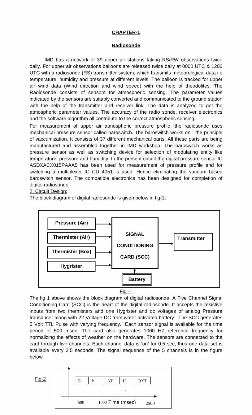
Fig.-1 The fig 1 above shows the block diagram of digital radiosonde. A Five Channel Signal Conditioning Card (SCC) is the heart of the digital radiosonde. It accepts the resistive inputs from two thermisters and one Hygrister and dc voltages of analog Pressure transducer along with 22 Voltage DC from water activated battery. The SCC generates 5 Volt TTL Pulse with varying frequency. Each sensor signal is available for the time period of 500 msec. The card also generates 1000 HZ reference frequency for normalizing the effects of weather on the hardware. The sensors are connected to the card through five channels. Each channel data is ‘on’ for 0.5 sec, thus one data set is available every 2.5 seconds. The signal sequence of the 5 channels is in the figure below.
Fig-2
Pressure (Air)
Thermister (Air)
Thermister (Box)
Hygrister
SIGNAL
CONDITIONING
CARD (SCC)
Battery
Transmitter
500 1000 2500
R P AT H BXT
Time (msec)
1
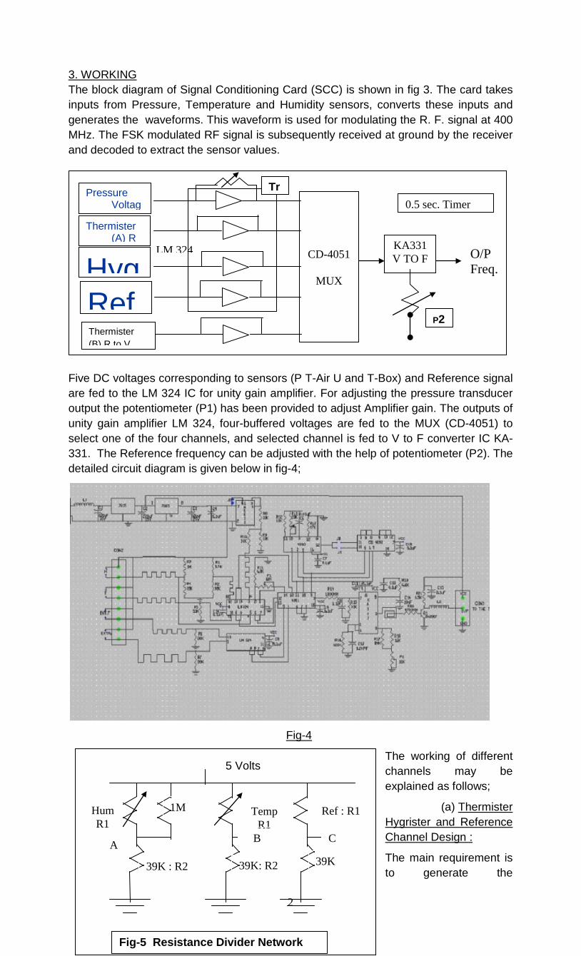
3. WORKING The block diagram of Signal Conditioning Card (SCC) is shown in fig 3. The card takes inputs from Pressure, Temperature and Humidity sensors, converts these inputs and generates the waveforms. This waveform is used for modulating the R. F. signal at 400 MHz. The FSK modulated RF signal is subsequently received at ground by the receiver and decoded to extract the sensor values.
Fig-3
Five DC voltages corresponding to sensors (P T-Air U and T-Box) and Reference signal are fed to the LM 324 IC for unity gain amplifier. For adjusting the pressure transducer output the potentiometer (P1) has been provided to adjust Amplifier gain. The outputs of unity gain amplifier LM 324, four-buffered voltages are fed to the MUX (CD-4051) to select one of the four channels, and selected channel is fed to V to F converter IC KA-331. The Reference frequency can be adjusted with the help of potentiometer (P2). The detailed circuit diagram is given below in fig-4;
Fig-4
The working of different channels may be explained as follows;
(a) Thermister Hygrister and Reference Channel Design :
The main requirement is to generate the
Hum R1
1M Temp R1
Ref : R1
A B C
39K : R2 39K: R2 39K
5 Volts
Fig-5 Resistance Divider Network
CD-4051
MUX
KA331 V TO F O/P
Freq.
0.5 sec. Timer Pressure
Voltag
Thermister (A) R
Hyg
Ref
Tr
P2
LM 324
Thermister (B) R to V
2
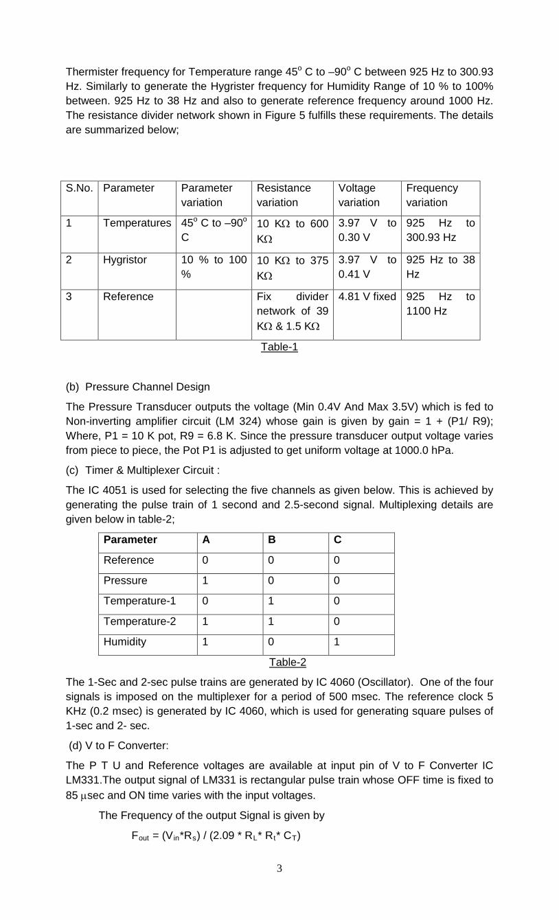
Thermister frequency for Temperature range 45o C to –90o C between 925 Hz to 300.93 Hz. Similarly to generate the Hygrister frequency for Humidity Range of 10 % to 100% between. 925 Hz to 38 Hz and also to generate reference frequency around 1000 Hz. The resistance divider network shown in Figure 5 fulfills these requirements. The details are summarized below;
S.No. Parameter Parameter variation
Resistance variation
Voltage variation
Frequency variation
1 Temperatures 45o C to –90o C
10 KΩ to 600 KΩ
3.97 V to 0.30 V
925 Hz to 300.93 Hz
2 Hygristor 10 % to 100 %
10 KΩ to 375 KΩ
3.97 V to 0.41 V
925 Hz to 38 Hz
3 Reference Fix divider network of 39 KΩ & 1.5 KΩ
4.81 V fixed 925 Hz to 1100 Hz
Table-1
(b) Pressure Channel Design
The Pressure Transducer outputs the voltage (Min 0.4V And Max 3.5V) which is fed to Non-inverting amplifier circuit (LM 324) whose gain is given by gain = 1 + (P1/ R9); Where, P1 = 10 K pot, R9 = 6.8 K. Since the pressure transducer output voltage varies from piece to piece, the Pot P1 is adjusted to get uniform voltage at 1000.0 hPa.
(c) Timer & Multiplexer Circuit :
The IC 4051 is used for selecting the five channels as given below. This is achieved by generating the pulse train of 1 second and 2.5-second signal. Multiplexing details are given below in table-2;
Parameter A B C
Reference 0 0 0
Pressure 1 0 0
Temperature-1 0 1 0
Temperature-2 1 1 0
Humidity 1 0 1
Table-2
The 1-Sec and 2-sec pulse trains are generated by IC 4060 (Oscillator). One of the four signals is imposed on the multiplexer for a period of 500 msec. The reference clock 5 KHz (0.2 msec) is generated by IC 4060, which is used for generating square pulses of 1-sec and 2- sec.
(d) V to F Converter:
The P T U and Reference voltages are available at input pin of V to F Converter IC LM331.The output signal of LM331 is rectangular pulse train whose OFF time is fixed to 85 µsec and ON time varies with the input voltages.
The Frequency of the output Signal is given by
Fout = (Vin*Rs) / (2.09 * RL* Rt* CT)
3
Rs = (R17 | | R18) + P2 = 18.2 K; RL (R16) = 820 K CT (C8) = 10 nf;
The Rs , RL and CL (C6) decide the ON time and off Time of the pulse is decided by Rt (R19) and CT.
Toff = 1.1* Rt* CT = 74.8 µ sec
The Voltage Comparator compares a positive input voltage, V1 to voltage Vx. If V1 is greater, the comparator will trigger the one shot timer the output of timer will turn on both the frequency output transistor and switched current source for a period 74.8 µ sec.
During this period, the current ‘i’ will flow out of switched current source and provide a fixed amount of charge, Q a fixed amount of charge, Q = i * t, into the capacitor CL.
This will normally charge Vx up to a higher level than V1. At the end of timing period, the current ‘i’ will turn off, and timer will reset itself.
Now there is no current and capacitor CL will be gradually discharged by RL until Vx fails to the level of V1. Then the comparator will trigger the timer and start another cycle.
The output of signal condition card is fed to a high frequency transmitter. The specifications of transmitter are given below;
Parameter Specification Frequency range 400 MHz – 406 MHz Frequency Step 1 MHz Carrier frequency settings By DIP switch settable Output Power +20 dBm at antenna input Antenna Gain 0 dBi Supply Voltage +5V Current
< 170mA Operating Temperature - 40oC to +60o C (with enclosure)
CHAPTER-2 Radiotheodolites / Sounding systems
1. SAMEER Radiotheodolite
SAMEER Radiotheodolite is manufactured by M/s SAMEER (Society for Applied Microwave Electronics Engineering and Research) Mumbai. It is a semi automatic
4
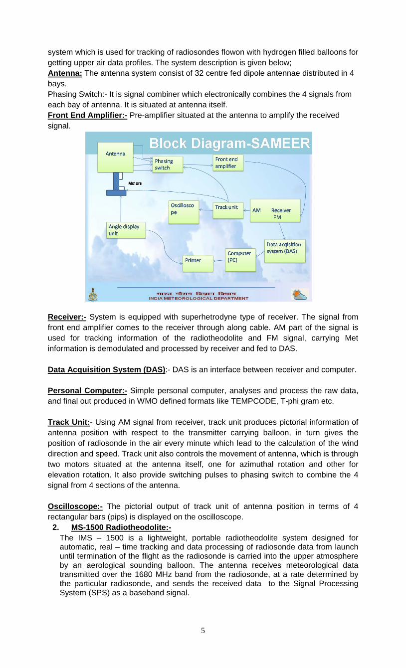
system which is used for tracking of radiosondes flowon with hydrogen filled balloons for getting upper air data profiles. The system description is given below; Antenna: The antenna system consist of 32 centre fed dipole antennae distributed in 4 bays. Phasing Switch:- It is signal combiner which electronically combines the 4 signals from each bay of antenna. It is situated at antenna itself. Front End Amplifier:- Pre-amplifier situated at the antenna to amplify the received signal.
Receiver:- System is equipped with superhetrodyne type of receiver. The signal from front end amplifier comes to the receiver through along cable. AM part of the signal is used for tracking information of the radiotheodolite and FM signal, carrying Met information is demodulated and processed by receiver and fed to DAS. Data Acquisition System (DAS):- DAS is an interface between receiver and computer. Personal Computer:- Simple personal computer, analyses and process the raw data, and final out produced in WMO defined formats like TEMPCODE, T-phi gram etc. Track Unit:- Using AM signal from receiver, track unit produces pictorial information of antenna position with respect to the transmitter carrying balloon, in turn gives the position of radiosonde in the air every minute which lead to the calculation of the wind direction and speed. Track unit also controls the movement of antenna, which is through two motors situated at the antenna itself, one for azimuthal rotation and other for elevation rotation. It also provide switching pulses to phasing switch to combine the 4 signal from 4 sections of the antenna. Oscilloscope:- The pictorial output of track unit of antenna position in terms of 4 rectangular bars (pips) is displayed on the oscilloscope.
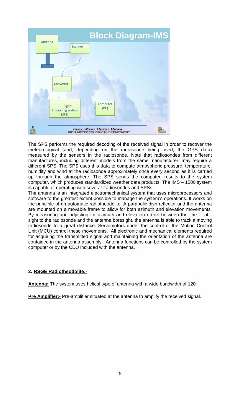
2. MS-1500 Radiotheodolite:- The IMS – 1500 is a lightweight, portable radiotheodolite system designed for automatic, real – time tracking and data processing of radiosonde data from launch until termination of the flight as the radiosonde is carried into the upper atmosphere by an aerological sounding balloon. The antenna receives meteorological data transmitted over the 1680 MHz band from the radiosonde, at a rate determined by the particular radiosonde, and sends the received data to the Signal Processing System (SPS) as a baseband signal.
5
Block Diagram-IMS Antenna
Scanner
Converter
Computer (PC)Signal
Processing system (SPS)
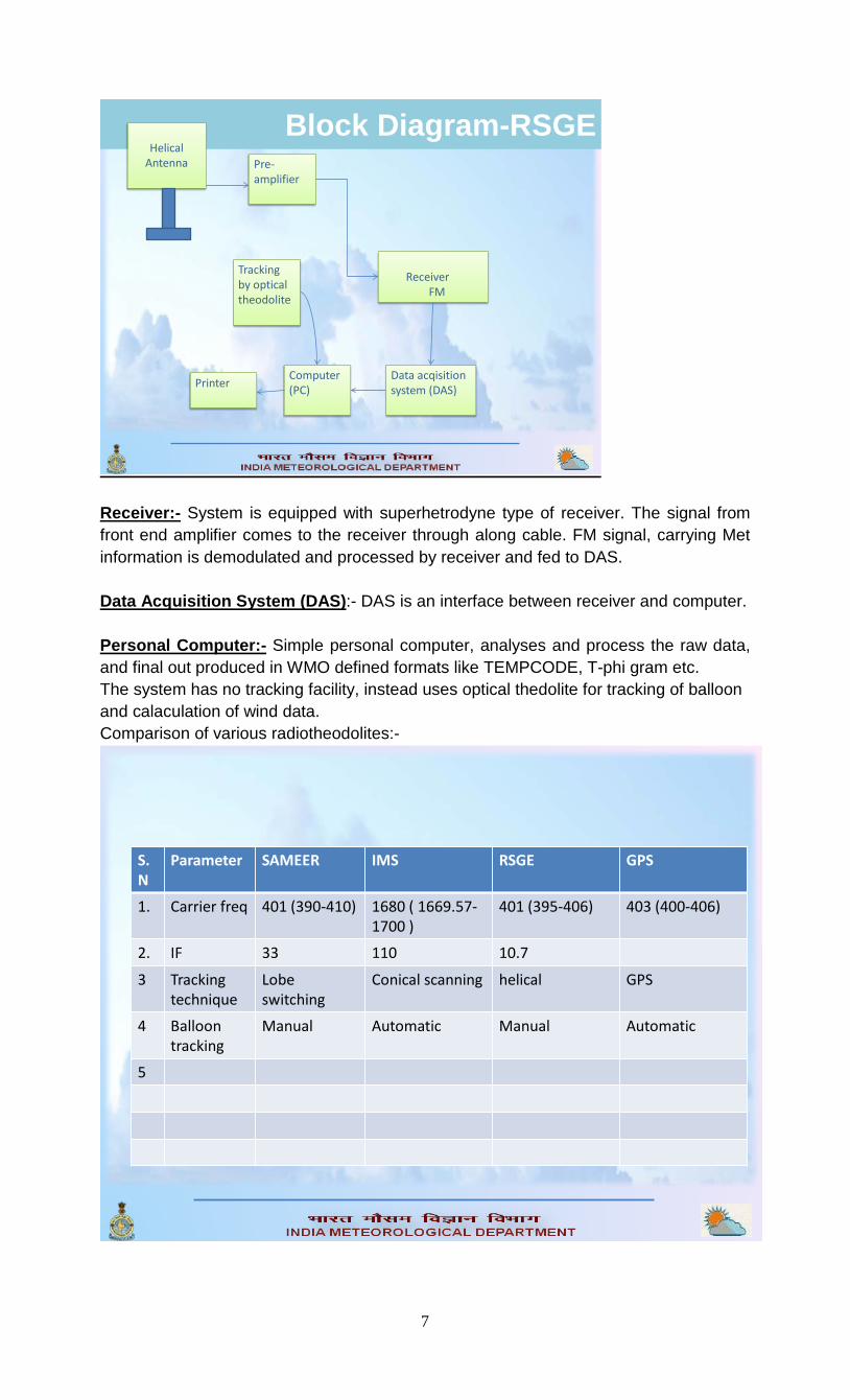
The SPS performs the required decoding of the received signal in order to recover the meteorological (and, depending on the radiosonde being used, the GPS data) measured by the sensors in the radiosonde. Note that radiosondes from different manufactures, including different models from the same manufacturer, may require a different SPS. The SPS uses this data to compute atmospheric pressure, temperature, humidity and wind at the radiosonde approximately once every second as it is carried up through the atmosphere. The SPS sends the computed results to the system computer, which produces standardized weather data products. The IMS – 1500 system is capable of operating with several radiosondes and SPSs. The antenna is an integrated electromechanical system that uses microprocessors and software to the greatest extent possible to manage the system’s operations. It works on the principle of an automatic radiotheodolite. A parabolic dish reflector and the antenna are mounted on a movable frame to allow for both azimuth and elevation movements. By measuring and adjusting for azimuth and elevation errors between the line - of - sight to the radiosonde and the antenna boresight, the antenna is able to track a moving radiosonde to a great distance. Servomotors under the control of the Motion Control Unit (MCU) control these movements. All electronic and mechanical elements required for acquiring the transmitted signal and maintaining the orientation of the antenna are contained in the antenna assembly. Antenna functions can be controlled by the system computer or by the CDU included with the antenna. 2. RSGE Radiotheodolite:- Antenna: The system uses helical type of antenna with a wide bandwidth of 1200. Pre Amplifier:- Pre-amplifier situated at the antenna to amplify the received signal.
6
Block Diagram-RSGE Helical
Antenna Pre-amplifier
Data acqisitionsystem (DAS)
Computer (PC)
ReceiverFM
Tracking by optical theodolite
Printer
Receiver:- System is equipped with superhetrodyne type of receiver. The signal from front end amplifier comes to the receiver through along cable. FM signal, carrying Met information is demodulated and processed by receiver and fed to DAS. Data Acquisition System (DAS):- DAS is an interface between receiver and computer. Personal Computer:- Simple personal computer, analyses and process the raw data, and final out produced in WMO defined formats like TEMPCODE, T-phi gram etc. The system has no tracking facility, instead uses optical thedolite for tracking of balloon and calaculation of wind data. Comparison of various radiotheodolites:-
S.N
Parameter SAMEER IMS RSGE GPS
1. Carrier freq 401 (390-410) 1680 ( 1669.57-1700 )
401 (395-406) 403 (400-406)
2. IF 33 110 10.7
3 Trackingtechnique
Lobe switching
Conical scanning helical GPS
4 Balloon tracking
Manual Automatic Manual Automatic
5
7
CHAPTER-3
1. GPS based Radiosounding system
A. The GPS
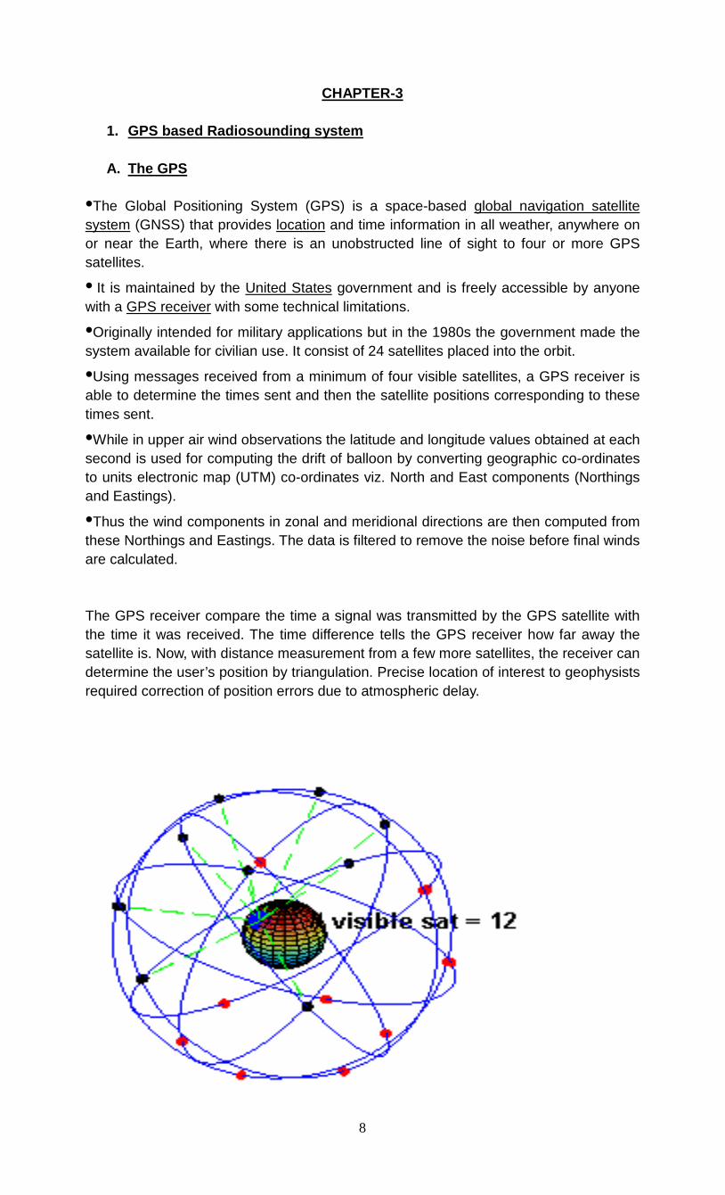
•The Global Positioning System (GPS) is a space-based global navigation satellite system (GNSS) that provides location and time information in all weather, anywhere on or near the Earth, where there is an unobstructed line of sight to four or more GPS satellites.
• It is maintained by the United States government and is freely accessible by anyone with a GPS receiver with some technical limitations.
•Originally intended for military applications but in the 1980s the government made the system available for civilian use. It consist of 24 satellites placed into the orbit.
•Using messages received from a minimum of four visible satellites, a GPS receiver is able to determine the times sent and then the satellite positions corresponding to these times sent.
•While in upper air wind observations the latitude and longitude values obtained at each second is used for computing the drift of balloon by converting geographic co-ordinates to units electronic map (UTM) co-ordinates viz. North and East components (Northings and Eastings).
•Thus the wind components in zonal and meridional directions are then computed from these Northings and Eastings. The data is filtered to remove the noise before final winds are calculated. The GPS receiver compare the time a signal was transmitted by the GPS satellite with the time it was received. The time difference tells the GPS receiver how far away the satellite is. Now, with distance measurement from a few more satellites, the receiver can determine the user’s position by triangulation. Precise location of interest to geophysists required correction of position errors due to atmospheric delay.
8
B. Radiosounding system
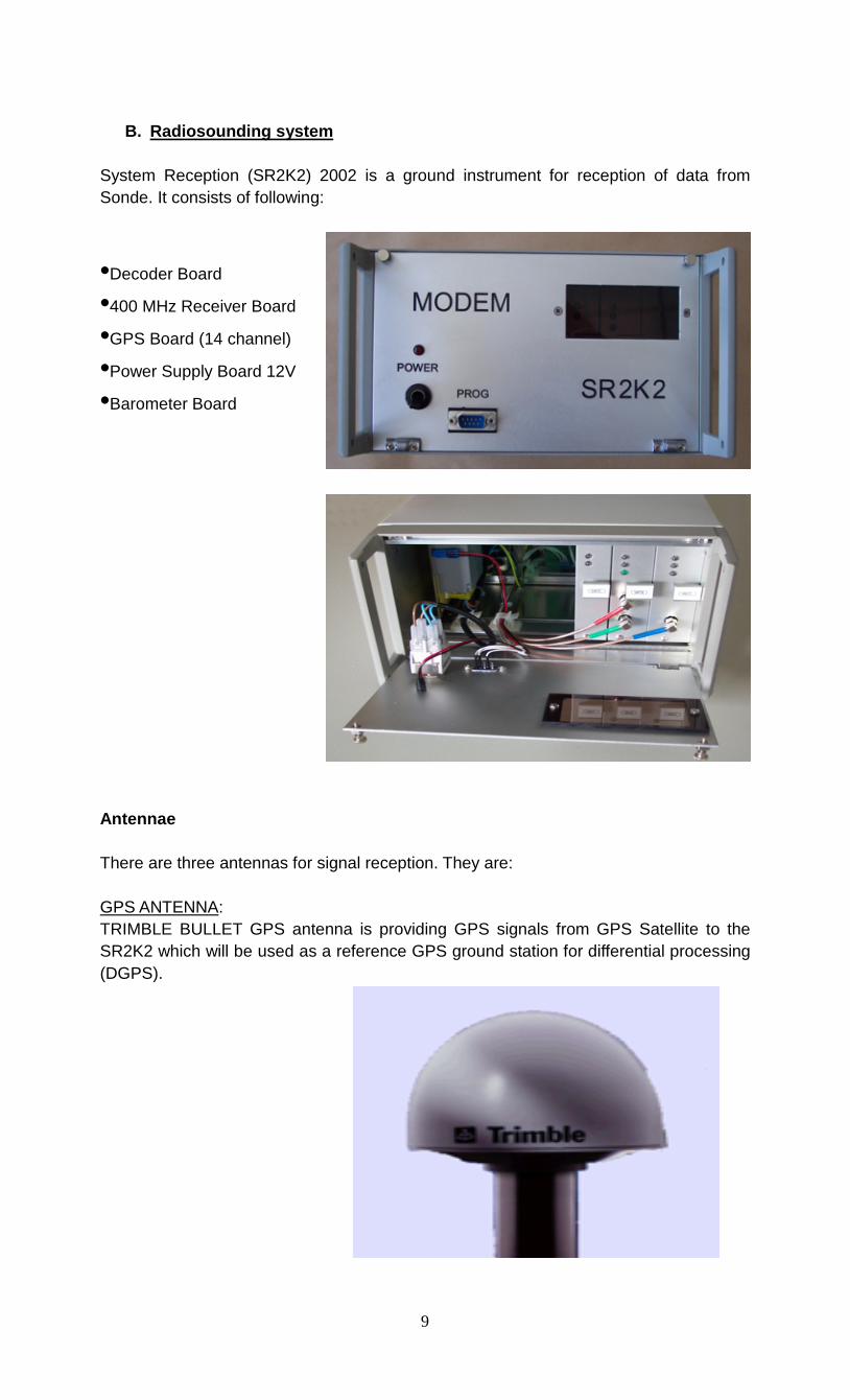
System Reception (SR2K2) 2002 is a ground instrument for reception of data from Sonde. It consists of following:
•Decoder Board
•400 MHz Receiver Board
•GPS Board (14 channel)
•Power Supply Board 12V
•Barometer Board
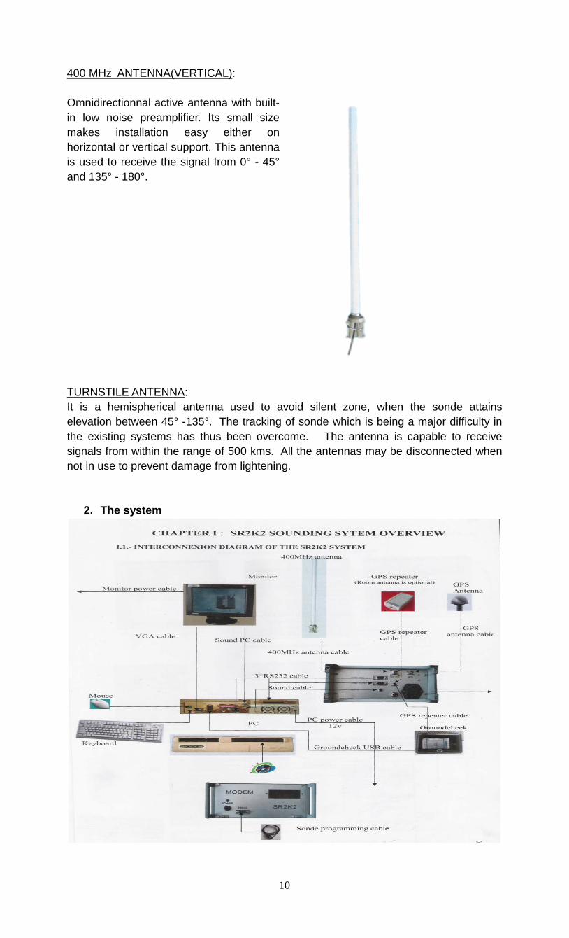
Antennae There are three antennas for signal reception. They are: GPS ANTENNA: TRIMBLE BULLET GPS antenna is providing GPS signals from GPS Satellite to the SR2K2 which will be used as a reference GPS ground station for differential processing (DGPS).
9
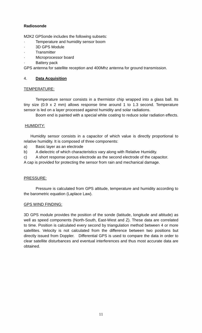
400 MHz ANTENNA(VERTICAL): Omnidirectionnal active antenna with built-in low noise preamplifier. Its small size makes installation easy either on horizontal or vertical support. This antenna is used to receive the signal from 0° - 45° and 135° - 180°.
TURNSTILE ANTENNA: It is a hemispherical antenna used to avoid silent zone, when the sonde attains elevation between 45° -135°. The tracking of sonde which is being a major difficulty in the existing systems has thus been overcome. The antenna is capable to receive signals from within the range of 500 kms. All the antennas may be disconnected when not in use to prevent damage from lightening.
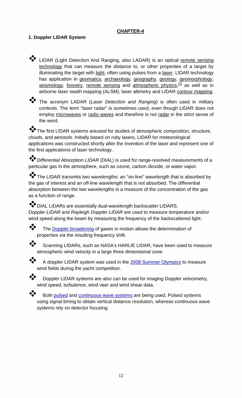
2. The system
10
Radiosonde M2K2 GPSonde includes the following subsets: · Temperature and humidity sensor boom · 3D GPS Module · Transmitter · Microprocessor board · Battery pack GPS antenna for satellite reception and 400Mhz antenna for ground transmission. 4. Data Acquisition TEMPERATURE: Temperature sensor consists in a thermistor chip wrapped into a glass ball. Its tiny size (0.9 x 2 mm) allows response time around 1 to 1.3 second. Temperature sensor is led on a layer processed against humidity and solar radiations. Boom end is painted with a special white coating to reduce solar radiation effects. HUMIDITY: Humidity sensor consists in a capacitor of which value is directly proportional to relative humidity. It is composed of three components: a) Basic layer as an electrode b) A dielectric of which characteristics vary along with Relative Humidity. c) A short response porous electrode as the second electrode of the capacitor. A cap is provided for protecting the sensor from rain and mechanical damage. PRESSURE: Pressure is calculated from GPS altitude, temperature and humidity according to the barometric equation (Laplace Law). GPS WIND FINDING: 3D GPS module provides the position of the sonde (latitude, longitude and altitude) as well as speed components (North-South, East-West and Z). These data are correlated to time. Position is calculated every second by triangulation method between 4 or more satellites. Velocity is not calculated from the difference between two positions but directly issued from Doppler. Differential GPS is used to compare the data in order to clear satellite disturbances and eventual interferences and thus most accurate data are obtained.
11
CHAPTER-4 1. Doppler LIDAR System
LIDAR (Light Detection And Ranging, also LADAR) is an optical remote sensing technology that can measure the distance to, or other properties of a target by illuminating the target with light, often using pulses from a laser. LIDAR technology has application in geomatics, archaeology, geography, geology, geomorphology, seismology, forestry, remote sensing and atmospheric physics,[1] as well as in airborne laser swath mapping (ALSM), laser altimetry and LIDAR contour mapping.
The acronym LADAR (Laser Detection and Ranging) is often used in military contexts. The term "laser radar" is sometimes used, even though LIDAR does not employ microwaves or radio waves and therefore is not radar in the strict sense of the word.
The first LIDAR systems areused for studies of atmospheric composition, structure, clouds, and aerosols. Initially based on ruby lasers, LIDAR for meteorological applications was constructed shortly after the invention of the laser and represent one of the first applications of laser technology.
Differential Absorption LIDAR (DIAL) is used for range-resolved measurements of a particular gas in the atmosphere, such as ozone, carbon dioxide, or water vapor.
The LIDAR transmits two wavelengths: an "on-line" wavelength that is absorbed by the gas of interest and an off-line wavelength that is not absorbed. The differential absorption between the two wavelengths is a measure of the concentration of the gas as a function of range.
DIAL LIDARs are essentially dual-wavelength backscatter LIDARS. Doppler LIDAR and Rayleigh Doppler LIDAR are used to measure temperature and/or wind speed along the beam by measuring the frequency of the backscattered light.
The Doppler broadening of gases in motion allows the determination of properties via the resulting frequency shift.
Scanning LIDARs, such as NASA's HARLIE LIDAR, have been used to measure atmospheric wind velocity in a large three dimensional cone.
A doppler LIDAR system was used in the 2008 Summer Olympics to measure wind fields during the yacht competition.
Doppler LIDAR systems are also can be used for imaging Doppler velocimetry, wind speed, turbulence, wind veer and wind shear data.
Both pulsed and continuous wave systems are being used. Pulsed systems using signal timing to obtain vertical distance resolution, whereas continuous wave systems rely on detector focusing.
12
2. Wind Profilers:- Most important requirement of NOWCAST system is un-interrupted observation and data supply on near real time basis. In case of upper wind observations, Wind Profilers are capable to provide hourly or more frequent wind speed and direction values as a function of altitude.
A wind profiler is a type of weather observing equipment that uses radar to detect the wind speed and direction at various elevations above the ground.
Readings are made at different heights above sea level, up to the extent of the troposphere.
Above this level there is inadequate water vapour present to produce a radar "bounce."
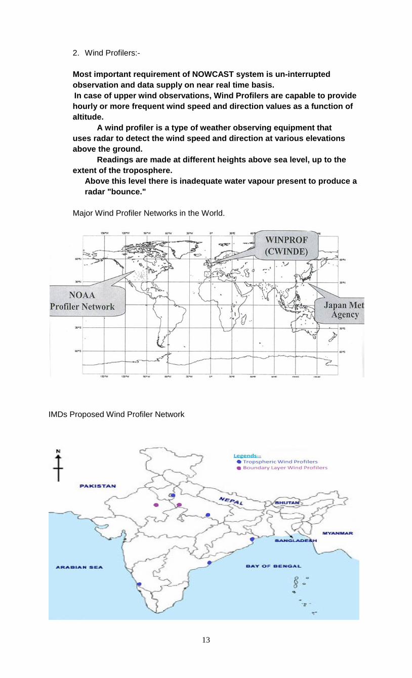
Major Wind Profiler Networks in the World.
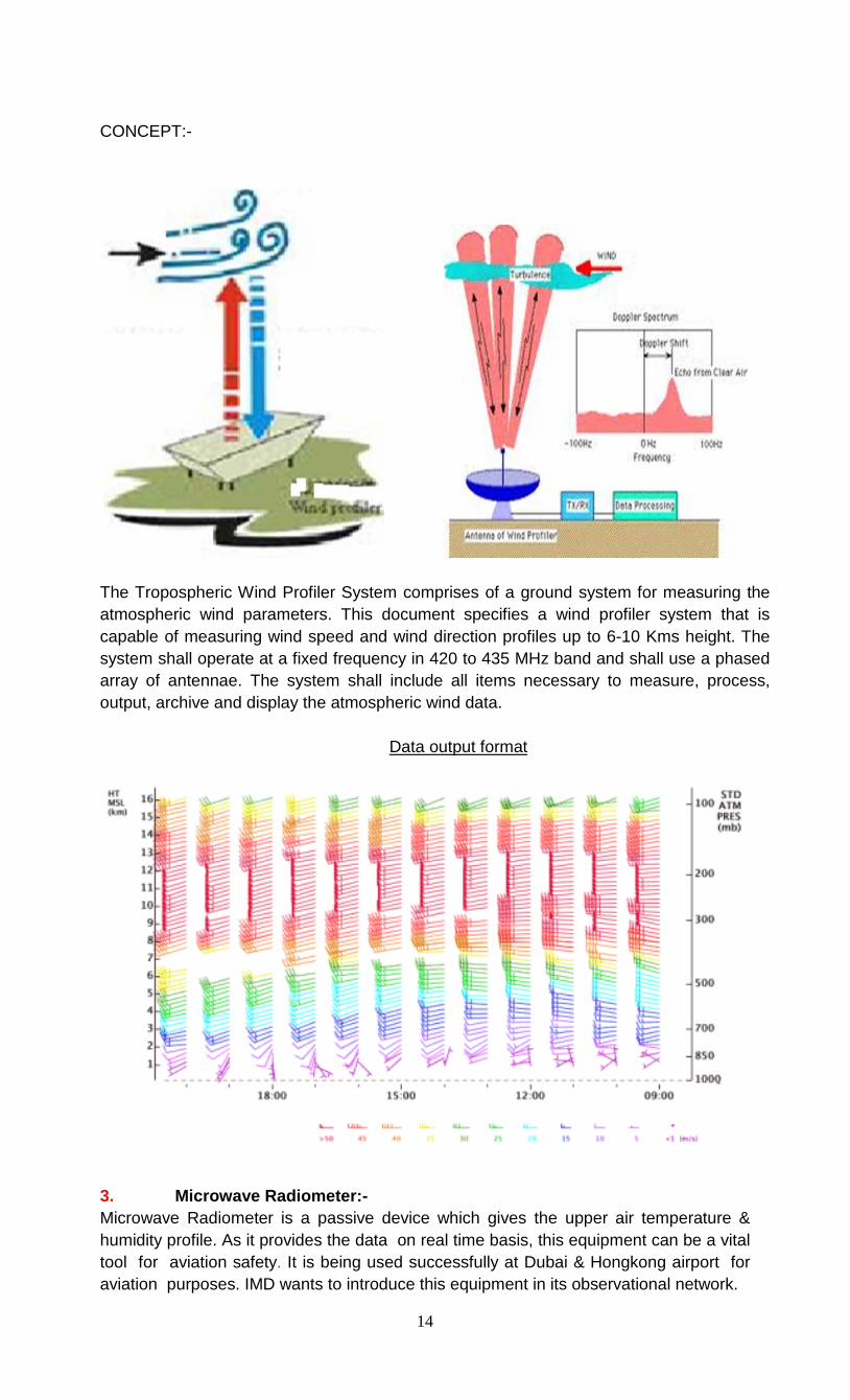
IMDs Proposed Wind Profiler Network
13
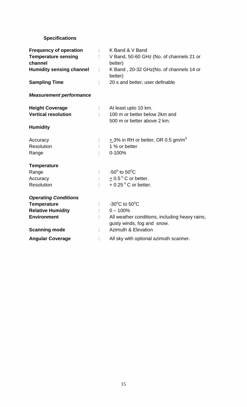
CONCEPT:-
The Tropospheric Wind Profiler System comprises of a ground system for measuring the atmospheric wind parameters. This document specifies a wind profiler system that is capable of measuring wind speed and wind direction profiles up to 6-10 Kms height. The system shall operate at a fixed frequency in 420 to 435 MHz band and shall use a phased array of antennae. The system shall include all items necessary to measure, process, output, archive and display the atmospheric wind data.
Data output format
3. Microwave Radiometer:- Microwave Radiometer is a passive device which gives the upper air temperature & humidity profile. As it provides the data on real time basis, this equipment can be a vital tool for aviation safety. It is being used successfully at Dubai & Hongkong airport for aviation purposes. IMD wants to introduce this equipment in its observational network.
14
Specifications
Frequency of operation : K Band & V Band Temperature sensing channel
: V Band, 50-60 GHz (No. of channels 21 or better)
Humidity sensing channel : K Band , 20-32 GHz(No. of channels 14 or better)
Sampling Time : 20 s and better, user definable Measurement performance Height Coverage
:
At least upto 10 km.
Vertical resolution Humidity Accuracy
: :
100 m or better below 2km and 500 m or better above 2 km. + 3% in RH or better, OR 0.5 gm/m3
Resolution : 1 % or better Range Temperature
: 0-100%
Range : -50o to 50oC Accuracy : + 0.5 o C or better. Resolution : + 0.25 o C or better. Operating Conditions Temperature
:
-30oC to 50oC
Relative Humidity Environment
: :
0 – 100% All weather conditions, including heavy rains, gusty winds, fog and snow.
Scanning mode : Azimuth & Elevation
Angular Coverage : All sky with optional azimuth scanner.
15
CHAPTER-5
Balloon filling and gas handling
Hydrogen gas is regularly produced at Hydrogen Factory, Agra presently and
supplied to the stations in upper air network of IMD. The Hydrogen factory was set up at Agra in the year 1925 in order to meet fully the requirements of compressed gas of IMD. The hydrogen gas is also supplied to IAF, SASE, VSSC, Antarctica/ Sagar Kanya etc. The H. F. Agra is manufacturing gas by Electrolysis process using distilled water and some quantity of Caustic–soda as a material input. The present production capacity of it is about 100 to 120 Cu.m in standard condition. The optimum annual production of H. F. Agra is 28000 cu.m. in standard conditions. Frequent power failure adversely affects its production. The compressed gas is utilized for filling meteorological balloons for pilot balloon observations and some time for RS/RW observations.
Hydrogen gas is also produced in situ at RS/RW stations in cylindrical generators by using ferrosilicon and caustic soda mixing with water. Inflation Gas. Hydrogen or helium gas should be used at all upper-air facilities. The determination of the source of hydrogen gas to be used for balloon inflation shall be made on the basis of operational and economic feasibility. Helium gas shall be substituted for hydrogen gas at facilities determined to be impractical or unsafe for hydrogen. Hydrogen Cylinders. Hydrogen cylinders shall be stored in non-metallic racks and secured with cables with non-metallic surfaces. Only ISI marked Cylinders shall be used. Cylinders shall be inspected upon arrival to assure that they have been pressure tested. A pressure test is required every five to ten years. Cylinders which will require testing in the near future should be used first. Heat/Leak Detectors. • Heat detectors are required for all hydrogen cylinders and generators. • Temperature sensitive tabs or crayons should be used to mark all hydrogen cylinders, and tabs should be used to mark all hydrogen generator cell head bolts to enable detection of hydrogen fires. • Leak detecting fluids should be stored in the inflation building so that hydrogen gas leaks can be easily detected. • Department shall determine the best gas heat/leak detectors for the type of generation method being used. Inflation Equipment--Hydrogen Cylinders. Upper-air sites using hydrogen from cylinders shall inflate balloons using only one cylinder at a time. The cylinders shall never be moved during inflation and should be kept within the storage room. Cylinders shall be properly secured so that they won't fall over or generate sparks. An approved multi-stage regulator should be attached to the cylinder in use and hydrogen should be routed to the balloon at low pressure via the special piping. Valves shall be kept closed on all cylinders not being used for inflation and the protective cap should be kept in place. If a cylinder's protective cap cannot be removed or the valve opened using normal hand exertion, mark the cylinder as defective. Use only approved spark-proof tools for cap removal. Cylinder valves shall be kept closed while attaching or removing a regulator.
16
Never let hydrogen escape into the free atmosphere. Improper practices which allow hydrogen to bleed from the cylinder are dangerous and could result in an unexpected ignition. Whenever a leak is suspected, test for escaping hydrogen gas by using a solution formulated for detecting leaks. Should a leak be discovered, mark the cylinder as defective. Inflation Equipment--Hydrogen Generators. • Operators of hydrogen generating equipment shall satisfactorily complete an upper-air operator's training course, or be certified by the station-in-charge to have demonstrated Proficiency. • Hydrogen Generator Operating Instructions shall be posted in plain view in close proximity to the generator itself within the inflation building. • RS/RW unit shall ensure that all persons working with the hydrogen generator are familiar with the operating and safety instructions. Earthing / Grounding. • The nozzle, weights, cutoff valve, regulator, and cylinder shall be connected to a common ground by a qualified person trained for this task. • Grounding straps are required around the fill bench to assure passive grounding of the operator during filling operations. • This requirement is particularly vital when the ambient relative humidity is below 50 percent. • Grounding straps should also be provided for balloons during the fill operation and should remain connected to the balloon while it is secured to the fill bench awaiting release. • A grounding strap arrangement is required around the drain port of the hydrogen storage tank on hydrogen generators. • The proper functioning of all grounds shall be ensured and documented by the station every six months. • The station shall ensure that all grounds are inspected visually by the observer before each filling and that any defective ground is repaired immediately. • The balloon fill nozzle shall be grounded to a common ground with the frame of the building and the remainder of the fill system.
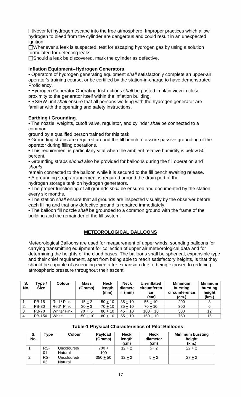
METEOROLOGICAL BALLOONS
Meteorological Balloons are used for measurement of upper winds, sounding balloons for carrying transmitting equipment for collection of upper air meteorological data and for determining the heights of the cloud bases. The balloons shall be spherical, expansible type and their chief requirement, apart from being able to reach satisfactory heights, is that they should be capable of ascending even after expansion due to being exposed to reducing atmospheric pressure throughout their ascent.
Table-1 Physical Characteristics of Pilot Balloons
S. No.
Type / Size
Colour Mass (Grams)
Neck length (mm)
Neck diameter (mm)
Un-inflated circumferen
ce (cm)
Minimum bursting
circumference (cm.)
Minimum bursting height (km.)
1 PB-15 Red / Pink 15 + 2 50 + 10 35 + 10 55 + 10 200 3 2. PB-30 Red/ Pink 30 + 3 70 + 10 35 + 10 70 + 10 300 6 3 PB-70 White/ Pink 70 + 5 80 + 10 45 + 10 100 + 10 500 12 4 PB-150 White 150 + 10 80 + 10 55 + 10 150 + 10 750 16
S. No.
Type Colour Payload (Grams)
Neck length (cm)
Neck diameter
(cm)
Minimum bursting height (km.)
1 RS-01
Uncoloured/ Natural
700 + 100
12 + 2 5+ 2 22 + 2
2 RS-02
Uncoloured/ Natural
350 + 50 12 + 2 5 + 2 27 + 2
17
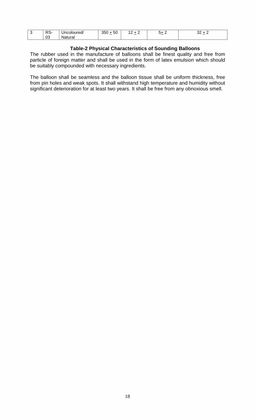
Table-2 Physical Characteristics of Sounding Balloons
The rubber used in the manufacture of balloons shall be finest quality and free from particle of foreign matter and shall be used in the form of latex emulsion which should be suitably compounded with necessary ingredients. The balloon shall be seamless and the balloon tissue shall be uniform thickness, free from pin holes and weak spots. It shall withstand high temperature and humidity without significant deterioration for at least two years. It shall be free from any obnoxious smell.
3 RS-03
Uncoloured/ Natural
350 + 50 12 + 2 5+ 2 32 + 2
18