chapter 1: power distribution and control
TRANSCRIPT

Whitaker, Jerry C. “Power Distribution and Control”AC Power Systems Handbook, 2nd Edition.Jerry C. WhitakerBoca Raton: CRC Press LLC, 1999
© 1999 CRC Press LLC
Chapter
1Power Distribution and
Control
1.1 Introduction
Every electronic installation requires a steady supply of clean power to functionproperly. Recent advances in technology have made the question of alternating cur-rent (ac) power quality even more important, as microcomputers are integrated intoa wide variety of electronic products. The high-speed logic systems prevalent todaycan garble or lose data because of power-supply disturbances or interruptions.
When the subject of power quality is discussed, the mistaken assumption is oftenmade that the topic only has to do with computers. At one time this may have beentrue because data processing computers were among the first significant loads thatdid not always operate reliably on the raw power received from the serving electri-cal utility. With the widespread implementation of control by microprocessor-basedsingle-board computers (or single-chip computers), however, there is a host ofequipment that now operates at voltage levels and clock speeds similar to that of thedesktop or mainframe computer. Equipment as diverse as electronic instrumenta-tion, cash registers, scanners, motor drives, and television sets all depend upononboard computers to give them instructions. Thus, the quality of the power thisequipment receives is as important as that supplied to a data processing center. Thebroader category, which covers all such equipment, including computers, is perhapsbest described as sensitive electronic equipment.
The heart of the problem that seems to have suddenly appeared is that while theupper limit of circuit speed of modern digital devices is continuously being raised,the logic voltages have simultaneously been reduced. Such a relationship is not acci-dental. As more transistors and other devices are packed together onto the same sur-face area, the spacing between them is necessarily reduced. This reduced distance
© 1999 CRC Press LLC
between components tends to lower the time the circuit requires to perform itsdesigned function. A reduction in the operating voltage level is a necessary—andfrom the standpoint of overall performance, particularly heat dissipation, desir-able—by-product of the shrinking integrated circuit (IC) architectures.
The ac power line into a facility is, of course, the lifeblood of any operation. It isalso, however, a frequent source of equipment malfunctions and component failures.The utility company ac feed contains not only the 60 Hz power needed to run thefacility, but also a variety of voltage sags, surges, and transients. These abnormali-ties cause different problems for different types of equipment.
1.1.1 Defining Terms
To explain the ac power-distribution system, and how to protect sensitive loads fromdamage resulting from disturbances, it is necessary first to define key terms.
• Active filter. A switching power processor connected between the line and a non-linear load, with the purpose of reducing the harmonic currents generated by theload.
• Alternator. An ac generator.
• Boost rectifier. An unfiltered rectifier with a voltage-boosting dc/dc converterbetween it and the load that shapes the line current to maintain low distortion.
• Circular mil. The unit of measurement for current-carrying conductors. One milis equal to 0.001 inches (0.025 millimeters). One circular mil is equal to a circlewhose diameter is 0.001 inches. The area of a circle with a 1-inch diameter is1,000,000 circular mils.
• Common-mode noise. Unwanted signals in the form of voltages appearingbetween the local ground reference and each of the power conductors, includingneutral and the equipment ground.
• Cone of protection (lightning). The space enclosed by a cone formed with itsapex at the highest point of a lightning rod or protecting tower, the diameter ofthe base of the cone having a definite relationship to the height of the rod ortower. When overhead ground wires are used, the space protected is referred to asa protected zone.
• Cosmic rays. Charged particles (ions) emitted by all radiating bodies in space.
• Coulomb. A unit of electric charge. The coulomb is the quantity of electriccharge that passes the cross section of a conductor when the current is maintainedconstant at one ampere.
• Counter-electromotive force. The effective electromotive force within a systemthat opposes the passage of current in a specified direction.

© 1999 CRC Press LLC
• Counterpoise. A conductor or system of conductors arranged (typically) belowthe surface of the earth and connected to the footings of a tower or pole to pro-vide grounding for the structure.
• Demand meter. A measuring device used to monitor the power demand of a sys-tem; it compares the peak power of the system with the average power.
• Dielectric (ideal). An insulating material in which all of the energy required toestablish an electric field in the dielectric is recoverable when the field orimpressed voltage is removed. A perfect dielectric has zero conductivity, and allabsorption phenomena are absent. A complete vacuum is the only known perfectdielectric.
• Eddy currents. The currents that are induced in the body of a conducting mass bythe time variations of magnetic flux.
• Efficiency (electric equipment). Output power divided by input power, expressedas a percentage.
• Electromagnetic compatibility (EMC). The ability of a device, piece of equip-ment, or system to function satisfactorily in its electromagnetic environmentwithout introducing intolerable electromagnetic disturbances.
• Generator. A machine that converts mechanical power into electrical power. (Inthis publication, the terms “alternator” and “generator” will be used interchange-ably.)
• Grid stability. The capacity of a power distribution grid to supply the loads at anynode with stable voltages; its opposite is grid instability, manifested by irregularbehavior of the grid voltages at some nodes.
• Ground loop. Sections of conductors shared by two different electronic and/orelectric circuits, usually referring to circuit return paths.
• Horsepower. The basic unit of mechanical power. One horsepower (hp) equals550 foot-pounds per second or 746 watts.
• HVAC. Abbreviation for “heating, ventilation, and air conditioning” system.
• Hysteresis loss (magnetic, power, and distribution transformer). The energy lossin magnetic material that results from an alternating magnetic field as the ele-mentary magnets within the material seek to align themselves with the reversingfield.
• Impedance. A linear operator expressing the relationship between voltage andcurrent. The inverse of impedance is admittance.
• Induced voltage. A voltage produced around a closed path or circuit by a timerate of change in a magnetic flux linking that path when there is no relativemotion between the path or circuit and the magnetic flux.

© 1999 CRC Press LLC
• Joule. A unit of energy equal to one watt-second.
• Life safety system. Systems designed to protect life and property, such as emer-gency lighting, fire alarms, smoke exhaust and ventilating fans, and site security.
• Lightning flash. An electrostatic atmospheric discharge. The typical duration of alightning flash is approximately 0.5 seconds. A single flash is made up of variousdischarge components, usually including three or four high-current pulses calledstrokes.
• Metal-oxide varistor. A solid-state voltage-clamping device used for transientsuppression applications.
• Normal-mode noise. Unwanted signals in the form of voltages appearing in line-to-line and line-to-neutral signals.
• Permeability. A general term used to express relationships between magneticinduction and magnetizing force. These relationships are either: (1) absolute per-meability, which is the quotient of a change in magnetic induction divided by thecorresponding change in magnetizing force; or (2) specific (relative) permeabil-ity, which is the ratio of absolute permeability to the magnetic constant.
• Point of common coupling (PCC). The point at which the utility and the con-sumer’s power systems are connected (usually where the energy meter islocated).
• Power factor. The ratio of total watts to the total rms (root-mean-square) volt-amperes in a given circuit. Power factor = W/VA.
• Power quality. The degree to which the utility voltage approaches the ideal caseof a stable, uninterrupted, zero-distortion, and disturbance-free source.
• Radio frequency interference. Noise resulting from the interception of transmit-ted radio frequency energy.
• Reactance. The imaginary part of impedance.
• Reactive power. The quantity of “unused” power that is developed by reactivecomponents (inductive or capacitive) in an ac circuit or system.
• Safe operating area. A semiconductor device parameter, usually provided inchart form, that outlines the maximum permissible limits of operation.
• Saturation (in a transformer). The maximum intrinsic value of induction possiblein a material.
• Self-inductance. The property of an electric circuit whereby a change of currentinduces an electromotive force in that circuit.
• Single-phasing. A fault condition in which one of the three legs in a three-phasepower system becomes disconnected, usually because of an open fuse or faultcondition.
© 1999 CRC Press LLC
• Solar wind. Charged particles from the sun that continuously bombard the sur-face of the earth.
• Switching power supply. Any type of ac/ac, ac/dc, dc/ac, or dc/dc power con-verter using periodically operated switching elements. Energy-storage devices(capacitors and inductors) are usually included in such supplies.
• Transient disturbance. A voltage pulse of high energy and short durationimpressed upon the ac waveform. The overvoltage pulse may be one to 100 timesthe normal ac potential (or more in some cases) and may last up to 15 ms. Risetimes typically measure in the nanosecond range.
• Uninterruptible power system (UPS). An ac power-supply system that is used forcomputers and other sensitive loads to: (1) protect the load from power interrup-tions, and (2) protect the load from transient disturbances.
• VAR compensator. A switching power processor, operating at the line frequency,with the purpose of reducing the reactive power being produced by a piece ofload equipment.
• Voltage regulation. The deviation from a nominal voltage, expressed as a per-centage of the nominal voltage.
1.1.2 Power Electronics
Power electronics is a multidisciplinary technology that encompasses power semi-conductor devices, converter circuits, electrical machines, signal electronics, controltheory, microcomputers, very-large-scale integration (VLSI) circuits, and com-puter-aided design techniques. Power electronics in its present state has been possi-ble as a consequence of a century of technological evolution. In the late 19th andearly 20th centuries, the use of rotating machines for power control and conversionwas well known [1]. Popular examples are the Ward Leonard speed control of dcmotors and the Kramer and Scherbius drives of wound rotor induction motors.
The history of power electronics began with the introduction of the glass bulbmercury arc rectifier in 1900 [2]. Gradually, metal tank rectifiers, grid-controlledrectifiers, ignitions, phanotrons, and thyratrons were introduced. During World WarII, magnetic amplifiers based on saturable core reactors and selenium rectifiersbecame especially attractive because of their ruggedness, reliability, and radiation-hardened characteristics.
Possibly the greatest revolution in the history of electrical engineering occurredwith the invention of the transistor by Bardeen, Brattain, and Shockley at the BellTelephone Laboratories in 1948. In 1956, the same laboratory invented the PNPNtriggering transistor, which later came to be known as the thyristor or silicon con-trolled rectifier (SCR). In 1958, the General Electric Company introduced the firstcommercial thyristor, marking the beginning of the modern era of power electronics.Many different types of power semiconductor devices have been introduced since

© 1999 CRC Press LLC
that time, further pushing the limits of operating power and efficiency, and long-term reliability.
It is interesting to note that in modern power electronics systems, there are essen-tially two types of semiconductor elements: the power semiconductors, which canbe regarded as the muscle of the equipment, and the microelectronic control chips,which make up the brain. Both are digital in nature, except that one manipulatespower up to gigawatt levels and the other deals with milliwatts or microwatts.Today's power electronics systems integrate both of these end-of-the-spectrumdevices, providing large size and cost advantages, and intelligent operation.
1.2 AC Circuit Analysis
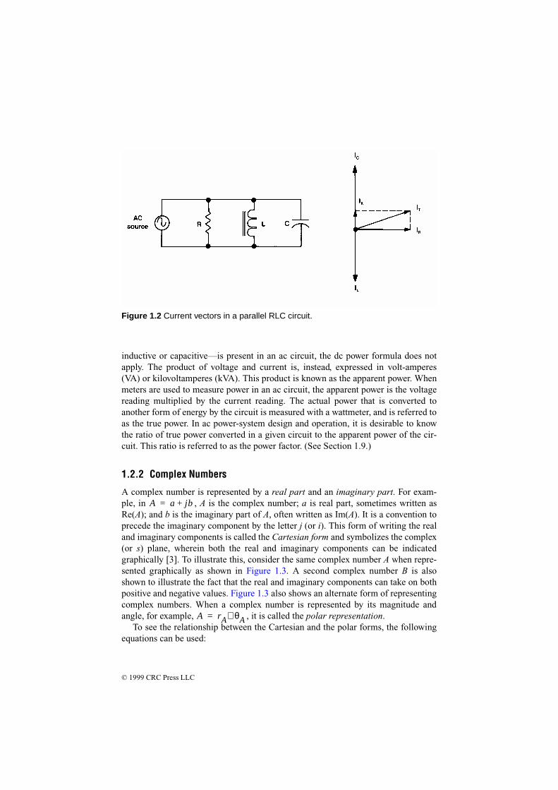
Vectors are used commonly in ac circuit analysis to represent voltage or current val-ues. Rather than using waveforms to show phase relationships, it is accepted prac-tice to use vector representations (sometimes called phasor diagrams). To begin avector diagram, a horizontal line is drawn, its left end being the reference point.Rotation in a counterclockwise direction from the reference point is considered to bepositive. Vectors may be used to compare voltage drops across the components of acircuit containing resistance, inductance, and/or capacitance. Figure 1.1 shows thevector relationship in a series RLC circuit, and Figure 1.2 shows a parallel RLC cir-cuit
1.2.1 Power Relationship in AC Circuits
In a dc circuit, power is equal to the product of voltage and current. This formulaalso is true for purely resistive ac circuits. However, when a reactance—either
Figure 1.1 Voltage vectors in a series RLC circuit.
© 1999 CRC Press LLC
inductive or capacitive—is present in an ac circuit, the dc power formula does notapply. The product of voltage and current is, instead, expressed in volt-amperes(VA) or kilovoltamperes (kVA). This product is known as the apparent power. Whenmeters are used to measure power in an ac circuit, the apparent power is the voltagereading multiplied by the current reading. The actual power that is converted toanother form of energy by the circuit is measured with a wattmeter, and is referred toas the true power. In ac power-system design and operation, it is desirable to knowthe ratio of true power converted in a given circuit to the apparent power of the cir-cuit. This ratio is referred to as the power factor. (See Section 1.9.)
1.2.2 Complex Numbers
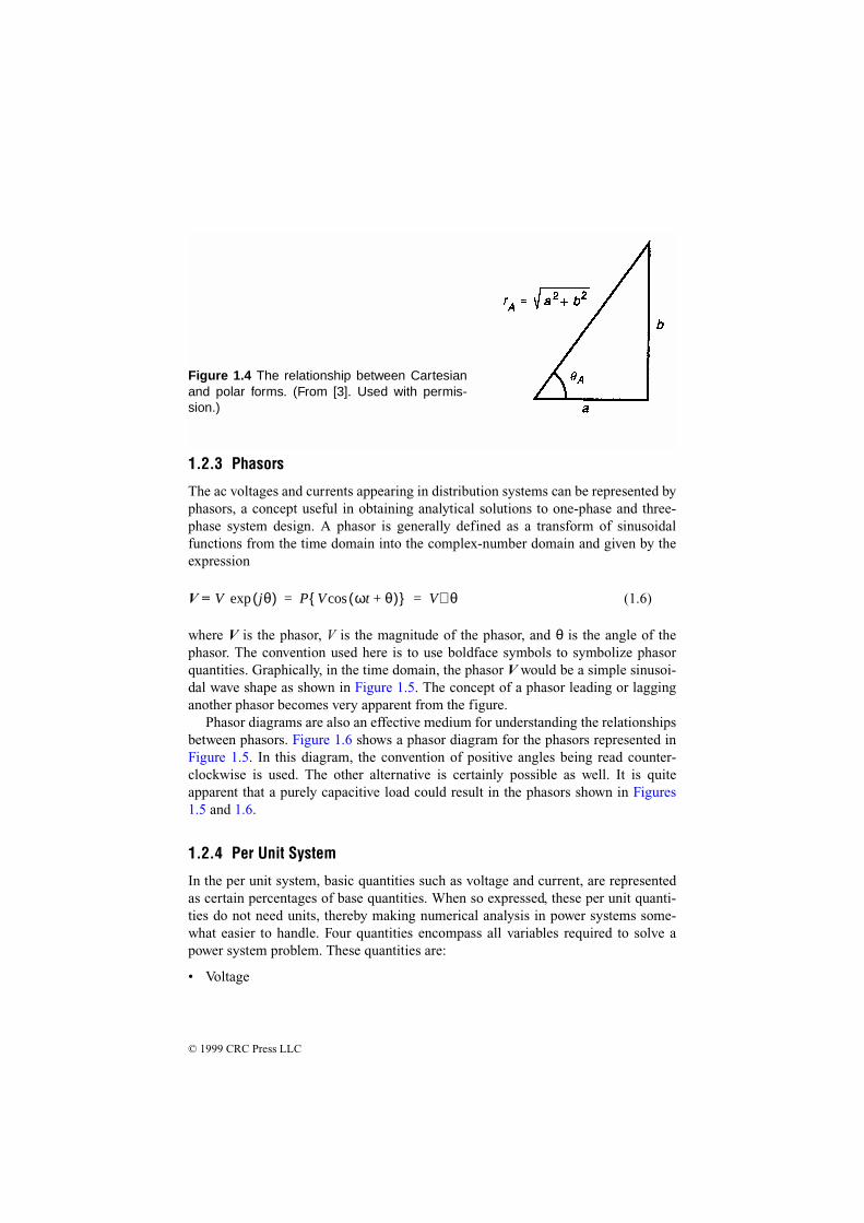
A complex number is represented by a real part and an imaginary part. For exam-ple, in , A is the complex number; a is real part, sometimes written asRe(A); and b is the imaginary part of A, often written as Im(A). It is a convention toprecede the imaginary component by the letter j (or i). This form of writing the realand imaginary components is called the Cartesian form and symbolizes the complex(or s) plane, wherein both the real and imaginary components can be indicatedgraphically [3]. To illustrate this, consider the same complex number A when repre-sented graphically as shown in Figure 1.3. A second complex number B is alsoshown to illustrate the fact that the real and imaginary components can take on bothpositive and negative values. Figure 1.3 also shows an alternate form of representingcomplex numbers. When a complex number is represented by its magnitude andangle, for example, , it is called the polar representation.
To see the relationship between the Cartesian and the polar forms, the followingequations can be used:
A a jb+=
A rA θA∠=
Figure 1.2 Current vectors in a parallel RLC circuit.

© 1999 CRC Press LLC
(1.1)
(1.2)
Conceptually, a better perspective can be obtained by investigating the triangleshown in Figure 1.4, and considering the trigonometric relationships. From this fig-ure, it can be seen that
(1.3)
(1.4)
The well-known Euler's identity is a convenient conversion of the polar and Car-tesian forms into an exponential form, given by
exp (j θ) = cos θ + j sin θ (1.5)
rA a2
b2
+=
θAba---
1–tan=
a Re A( ) rA θA( )cos= =
b Im A( ) rA θA( )sin= =
Figure 1.3 The s plane representing two complex numbers. (From [3]. Used with per-mission.)
© 1999 CRC Press LLC
1.2.3 Phasors
The ac voltages and currents appearing in distribution systems can be represented byphasors, a concept useful in obtaining analytical solutions to one-phase and three-phase system design. A phasor is generally defined as a transform of sinusoidalfunctions from the time domain into the complex-number domain and given by theexpression
V = (1.6)
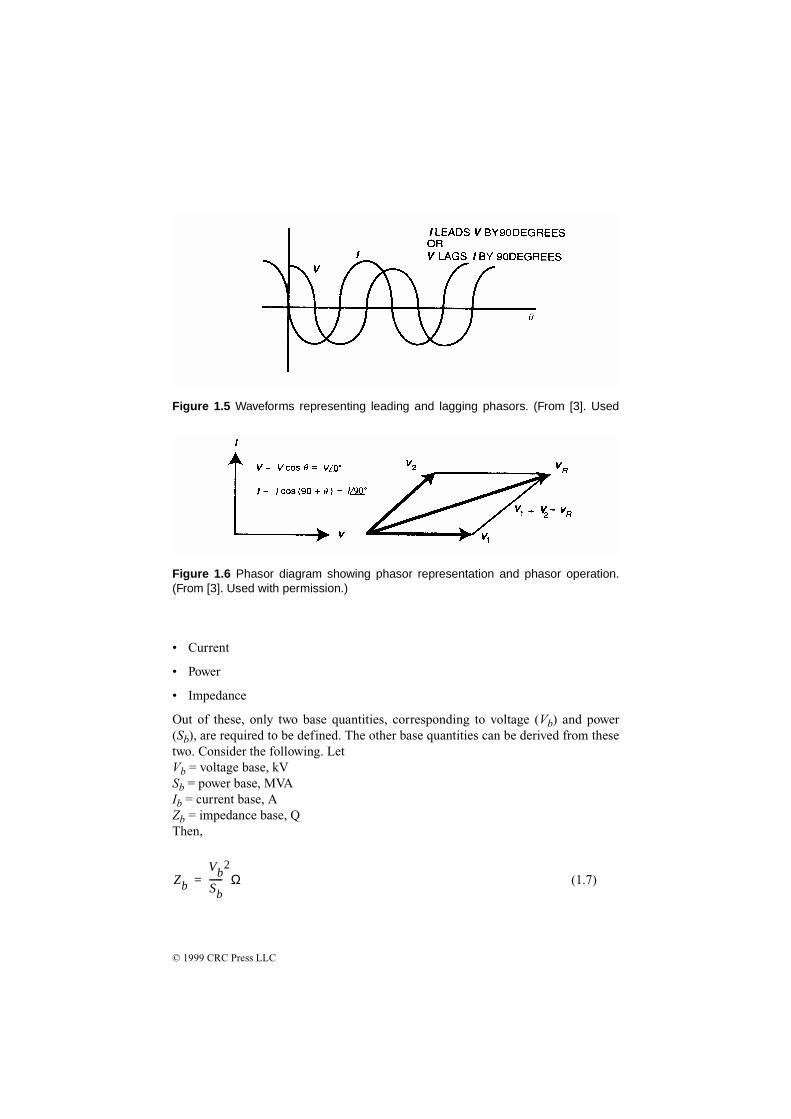
where V is the phasor, V is the magnitude of the phasor, and θ is the angle of thephasor. The convention used here is to use boldface symbols to symbolize phasorquantities. Graphically, in the time domain, the phasor V would be a simple sinusoi-dal wave shape as shown in Figure 1.5. The concept of a phasor leading or lagginganother phasor becomes very apparent from the figure.
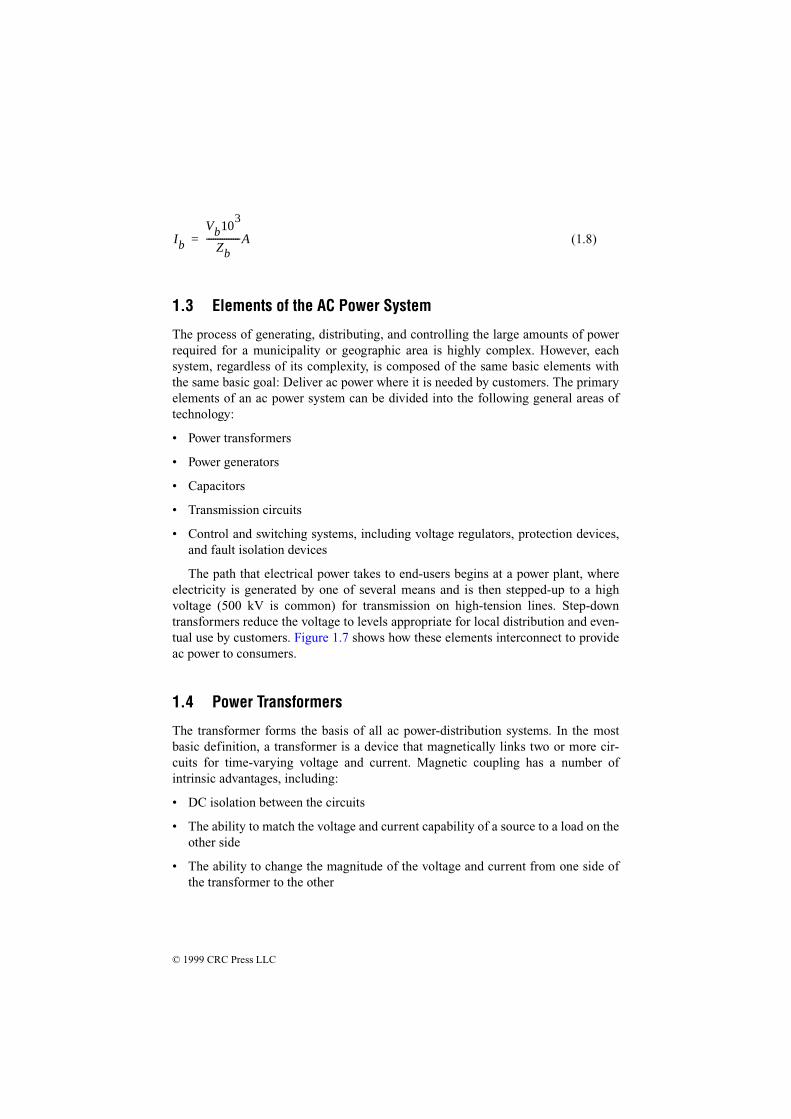
Phasor diagrams are also an effective medium for understanding the relationshipsbetween phasors. Figure 1.6 shows a phasor diagram for the phasors represented inFigure 1.5. In this diagram, the convention of positive angles being read counter-clockwise is used. The other alternative is certainly possible as well. It is quiteapparent that a purely capacitive load could result in the phasors shown in Figures1.5 and 1.6.
1.2.4 Per Unit System
In the per unit system, basic quantities such as voltage and current, are representedas certain percentages of base quantities. When so expressed, these per unit quanti-ties do not need units, thereby making numerical analysis in power systems some-what easier to handle. Four quantities encompass all variables required to solve apower system problem. These quantities are:
• Voltage
V jθ( )exp P V ωt θ+( )cos V θ∠= =
Figure 1.4 The relationship between Cartesianand polar forms. (From [3]. Used with permis-sion.)
© 1999 CRC Press LLC
• Current
• Power
• Impedance
Out of these, only two base quantities, corresponding to voltage (Vb) and power(Sb), are required to be defined. The other base quantities can be derived from thesetwo. Consider the following. LetVb = voltage base, kVSb = power base, MVAIb = current base, AZb = impedance base, QThen,
(1.7)Zb
VbSb------
2Ω=
Figure 1.6 Phasor diagram showing phasor representation and phasor operation.(From [3]. Used with permission.)
Figure 1.5 Waveforms representing leading and lagging phasors. (From [3]. Used
© 1999 CRC Press LLC
(1.8)
1.3 Elements of the AC Power System
The process of generating, distributing, and controlling the large amounts of powerrequired for a municipality or geographic area is highly complex. However, eachsystem, regardless of its complexity, is composed of the same basic elements withthe same basic goal: Deliver ac power where it is needed by customers. The primaryelements of an ac power system can be divided into the following general areas oftechnology:
• Power transformers
• Power generators
• Capacitors
• Transmission circuits
• Control and switching systems, including voltage regulators, protection devices,and fault isolation devices
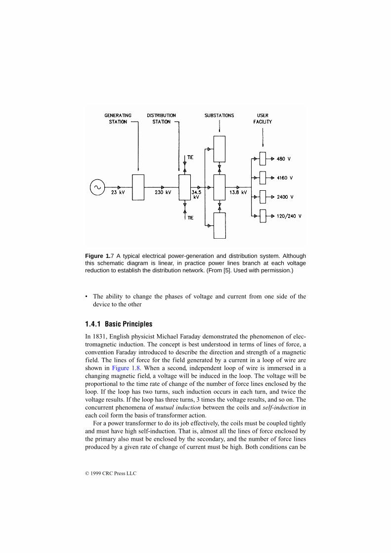
The path that electrical power takes to end-users begins at a power plant, whereelectricity is generated by one of several means and is then stepped-up to a highvoltage (500 kV is common) for transmission on high-tension lines. Step-downtransformers reduce the voltage to levels appropriate for local distribution and even-tual use by customers. Figure 1.7 shows how these elements interconnect to provideac power to consumers.
1.4 Power Transformers
The transformer forms the basis of all ac power-distribution systems. In the mostbasic definition, a transformer is a device that magnetically links two or more cir-cuits for time-varying voltage and current. Magnetic coupling has a number ofintrinsic advantages, including:
• DC isolation between the circuits
• The ability to match the voltage and current capability of a source to a load on theother side
• The ability to change the magnitude of the voltage and current from one side ofthe transformer to the other
Ib
Vb103
Zb---------------A=
© 1999 CRC Press LLC
Figure 1.7 A typical electrical power-generation and distribution system. Althoughthis schematic diagram is linear, in practice power lines branch at each voltagereduction to establish the distribution network. (From [5]. Used with permission.)
• The ability to change the phases of voltage and current from one side of thedevice to the other
1.4.1 Basic Principles
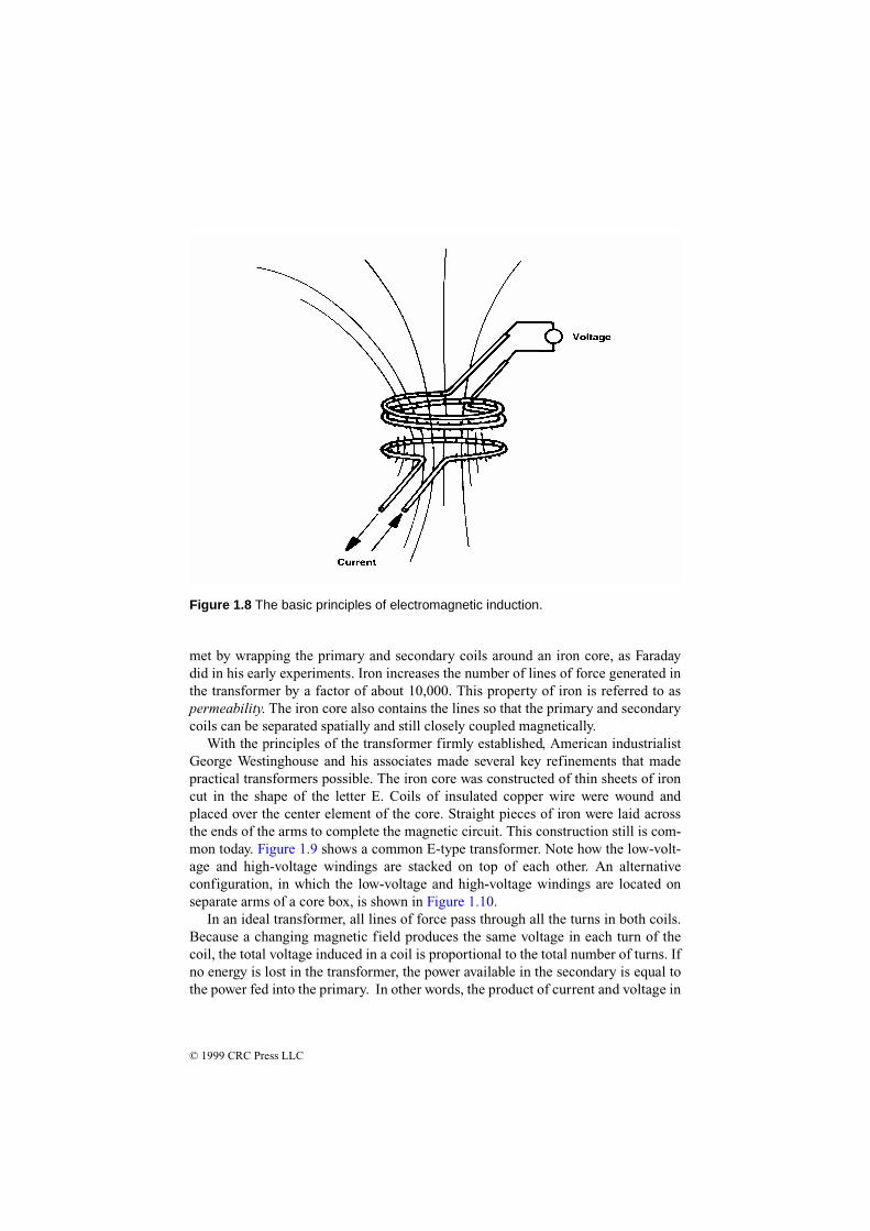
In 1831, English physicist Michael Faraday demonstrated the phenomenon of elec-tromagnetic induction. The concept is best understood in terms of lines of force, aconvention Faraday introduced to describe the direction and strength of a magneticfield. The lines of force for the field generated by a current in a loop of wire areshown in Figure 1.8. When a second, independent loop of wire is immersed in achanging magnetic field, a voltage will be induced in the loop. The voltage will beproportional to the time rate of change of the number of force lines enclosed by theloop. If the loop has two turns, such induction occurs in each turn, and twice thevoltage results. If the loop has three turns, 3 times the voltage results, and so on. Theconcurrent phenomena of mutual induction between the coils and self-induction ineach coil form the basis of transformer action.
For a power transformer to do its job effectively, the coils must be coupled tightlyand must have high self-induction. That is, almost all the lines of force enclosed bythe primary also must be enclosed by the secondary, and the number of force linesproduced by a given rate of change of current must be high. Both conditions can be
© 1999 CRC Press LLC
Figure 1.8 The basic principles of electromagnetic induction.
met by wrapping the primary and secondary coils around an iron core, as Faradaydid in his early experiments. Iron increases the number of lines of force generated inthe transformer by a factor of about 10,000. This property of iron is referred to aspermeability. The iron core also contains the lines so that the primary and secondarycoils can be separated spatially and still closely coupled magnetically.
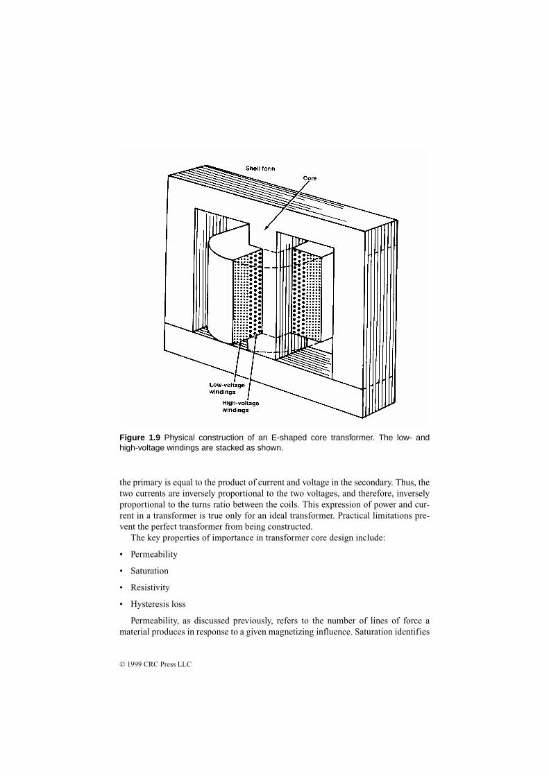
With the principles of the transformer firmly established, American industrialistGeorge Westinghouse and his associates made several key refinements that madepractical transformers possible. The iron core was constructed of thin sheets of ironcut in the shape of the letter E. Coils of insulated copper wire were wound andplaced over the center element of the core. Straight pieces of iron were laid acrossthe ends of the arms to complete the magnetic circuit. This construction still is com-mon today. Figure 1.9 shows a common E-type transformer. Note how the low-volt-age and high-voltage windings are stacked on top of each other. An alternativeconfiguration, in which the low-voltage and high-voltage windings are located onseparate arms of a core box, is shown in Figure 1.10.
In an ideal transformer, all lines of force pass through all the turns in both coils.Because a changing magnetic field produces the same voltage in each turn of thecoil, the total voltage induced in a coil is proportional to the total number of turns. Ifno energy is lost in the transformer, the power available in the secondary is equal tothe power fed into the primary. In other words, the product of current and voltage in
© 1999 CRC Press LLC
the primary is equal to the product of current and voltage in the secondary. Thus, thetwo currents are inversely proportional to the two voltages, and therefore, inverselyproportional to the turns ratio between the coils. This expression of power and cur-rent in a transformer is true only for an ideal transformer. Practical limitations pre-vent the perfect transformer from being constructed.
The key properties of importance in transformer core design include:
• Permeability
• Saturation
• Resistivity
• Hysteresis loss
Permeability, as discussed previously, refers to the number of lines of force amaterial produces in response to a given magnetizing influence. Saturation identifies
Figure 1.9 Physical construction of an E-shaped core transformer. The low- andhigh-voltage windings are stacked as shown.

© 1999 CRC Press LLC
the point at which the ability of the core to carry a magnetic force reaches a limitingplateau. These two properties define the power-handling capability of the core ele-ment. Electrical resistivity is desirable in the core because it minimizes energylosses resulting from eddy currents. In contrast, hysteresis undermines the efficiencyof a transformer. Because of the interactions among groups of magnetized atoms,losses are incurred as the frequency of the changing magnetic field is increased.Throughout the history of transformer development, the goal of the design engineerhas been to increase permeability, saturation, and resistivity, while decreasing hys-teresis losses. A variety of core materials, including silicon iron in various forms,have been used.
Transformer efficiency is defined as follows:
(1.9)PPoutPin
----------- 100×=
Figure 1.10 Transformer construction using a box core with physical separationbetween the low- and high-voltage windings.
© 1999 CRC Press LLC
Where:E = efficiency in percentPout = transformer power output in wattsPin = transformer power input in watts
Losses in a transformer are the result of copper losses in the windings and corelosses. The copper losses vary with the square of the current; the core losses varywith the input voltage magnitude and frequency. Because neither of these quantitiesdepends on the power being consumed by the load, power transformers are rated bythe voltamperes (VA) that flow through them.
The regulation specification of a power transformer is a measure of the trans-former’s ability to maintain a constant output voltage under varying loads. The pri-mary voltage is held constant at the value required to produce the rated voltage onthe secondary at full load:
(1.10)
Where:R = regulation in percentVs0 = secondary voltage under no loadVsfl = secondary voltage under full load
Also bearing on transformer performance are electrical insulation and the coolingsystem used. These two elements are intimately related because the amount of heatthat the core and conductors generate determines the longevity of the insulation; theinsulation itself—whether solid, liquid, or gas—serves to carry off some portion ofthe heat produced. Temperatures inside a commercial transformer may reach 100°C,the boiling point of water. Under such conditions, deterioration of insulating materi-als can limit the useful lifetime of the device. Although oils are inexpensive andeffective as insulators and coolants, some oils are flammable, making them unac-ceptable for units placed inside buildings. Chlorinated hydrocarbon liquids (PCBs)were used extensively from the 1930s to the late 1970s, but evidence of long-termtoxic effects prompted a ban on their use. (See Section 10.3.) Some transformersrely on air- or nitrogen-gas-based insulators. Such devices can be installed indoors.The breakdown strength of gas sometimes is enhanced through the addition of smallquantities of fluorocarbons. Other dry transformers depend on cast-resin insulationmade of polymerizing liquids that harden into high-integrity solids. Progress in heatremoval is largely responsible for reducing the overall size of the transformerassembly.
Modern high-power commercial transformers may operate at voltages of 750 kVor more and can handle more than 1000 kVA. The expected lifetime of a commercial
RVs0 Vsfl–
Vsfl------------------------ 100×=

© 1999 CRC Press LLC
power transformer ranges from 24 to 40 years. A typical three-phase oil-cooledtransformer is shown in Figure 1.11.
1.4.2 Counter-Electromotive Force
All transformers, generators, and motors exhibit the property of inductance. Thisproperty is the result of a counter-emf that is produced when a magnetic field is
(a)
Figure 1.11 Construction of an oil-filled three-phase power transformer used for com-mercial power distribution: (a) cutaway view; (b, next page) exterior view. (Drawing bfrom [14]. Used with permission.)

© 1999 CRC Press LLC
developed around a coil of wire. Inductance presents an opposition to the change incurrent flow in a circuit. This opposition is evident in the diagram shown in Figure1.12. In a purely inductive circuit (containing no resistance), the voltage will leadthe current by 90°. However, because all practical circuits have resistance, the offsetwill vary from one circuit to the next. Figure 1.13 illustrates a circuit in which volt-age leads current by 30°. The angular separation between voltage and current isreferred to as the phase angle. The phase angle increases as the inductance of thecircuit increases. Any inductive circuit exhibits the property of inductance, includ-ing electrical power-transmission and distribution lines. The henry (H) is the unit ofmeasurement for inductance. A circuit has a 1 H inductance if a current changing ata rate of 1 A/s produces an induced counter-emf of 1 V.
In an inductive circuit with ac applied, an opposition to current flow is created bythe inductance. This opposition is known as inductive reactance (Xl). The inductivereactance of a given ac circuit is determined by the inductance of the circuit and therate of current change. Inductive reactance can be expressed as:
Xl = 2 π f L (1.11)
Where:
Figure 11b.

© 1999 CRC Press LLC
Xl = inductive reactance in ohms2π = 6.28, the expression for one sine wave of alternating current (0° to 360°)f = frequency of the ac source in hertzL = inductance of the circuit in henrys
(a)
(b)
(c)
Figure 1.12 Purely inductive circuit: (a) circuit diagram; (b) representative wave-forms; (c) vector representation.

© 1999 CRC Press LLC
1.4.3 Full Load Percent Impedance
The full load percent impedance (FLPI) of a transformer is an important parameterin power-supply system design. FLPI is determined by the construction of the coreand physical spacing between the primary and secondary windings. Typical FLPI
(a)
(b)
(c)
Figure 1.13 Resistive-inductive circuit: (a) circuit diagram; (b) representative wave-forms; (c) vector representations.
© 1999 CRC Press LLC
values range from 1 percent to 5 percent. FLPI is a measure of the ability of a trans-former to maintain its rated voltage with a varying load. The lower the FLPI, thebetter the regulation. FLPI also determines the maximum fault current that the trans-former can deliver. For example, if a 5 percent FLPI transformer supplying 5 Anominal at the secondary is short-circuited, the device can, theoretically, supply 100A at full voltage. A similar transformer with a 10 percent FLPI can supply only 50 Awhen short-circuited. Typical short-circuit currents for a selection of small three-phase transformers are listed in Table 1.1.
1.4.4 Design Considerations
As touched upon previously, permeability µ describes the ease with which magneticflux can be produced in a given material. More flux will be produced in a materialwith a high permeability than in a one with a low permeability, given the sameamount of current and the same number of turns in the coil. The ratio of a material'spermeability to the permeability of free space, called relative permeability, is oftenused [4]. The actual permeability, which has units of webers per ampere-turn-meter,is found by multiplying the permeability of free space by the relative permeability.
The overall ability of a core to carry flux also depends on its size and shape, andits cross-sectional area. This is described by permeance. The basic relationship ofpermeance to permeability in a core is defined by
or (1.12)
Where:P = permeanceµ = permeability of the materialA = the cross-sectional area of the corel = the mean length of the flux path in the core
This equation assumes uniform flux distribution in the core and constant permeabil-ity inside the core. It does not take into account the variations in the length of theflux path from the inside of the core to the outside. The reciprocal of permeance isreluctance.
Figure 1.14 shows the magnetization curve for a typical ferromagnetic material.Note that the curve follows two different paths, depending on whether the mag-netizing force H is increasing or decreasing. This is called a hysteresis curve. It iscaused by the fact that the magnetic particles in the core need to be rotated andrealigned each time the polarity of the magnetizing force changes. This is why themagnetic force must be reversed to reduce the flux density to zero.
As the magnetizing force H increases, the flux density increases up to a point,and then the curve flattens out. In this flattened region only a small increase in theflux density can be achieved, as illustrated in the figure. The core is said to be satu-
PµAl
------- lR---= = R
lµA-------=

© 1999 CRC Press LLC
rated. The flattening of the curve indicates that the permeability has decreased fromthe value it had when there was only a small amount of flux passing through thecore.
To eliminate ambiguity in the voltage and current polarity at the input and outputof the transformer symbol, the dot convention is commonly used. In circuit dia-
Table 1.1 Full Load Percent Impedance Short-Circuit Currents for a Selection of Three-Phase Transformers
DC Amps (kVa/kV)
Full Load Percent Impedance
Symmetrical Short-Circuit Current
1 A 1 57.7
1 A 2 28.8
1 A 3 19.3
1 A 4 14.4
1 A 5 11.5
2 A 1 115.5
2 A 2 57.7
2 A 3 38.5
2 A 4 28.8
2 A 5 23.1
3 A 1 173.2
3 A 2 86.6
3 A 3 57.7
3 A 4 43.3
3 A 5 34.6
4 A 1 230.9
4 A 2 115.5
4 A 3 77.0
4 A 4 57.7
4 A 5 46.2
5 A 1 288.6
5 A 2 144.3
5 A 3 96.2
5 A 4 72.2
5 A 5 57.7

© 1999 CRC Press LLC
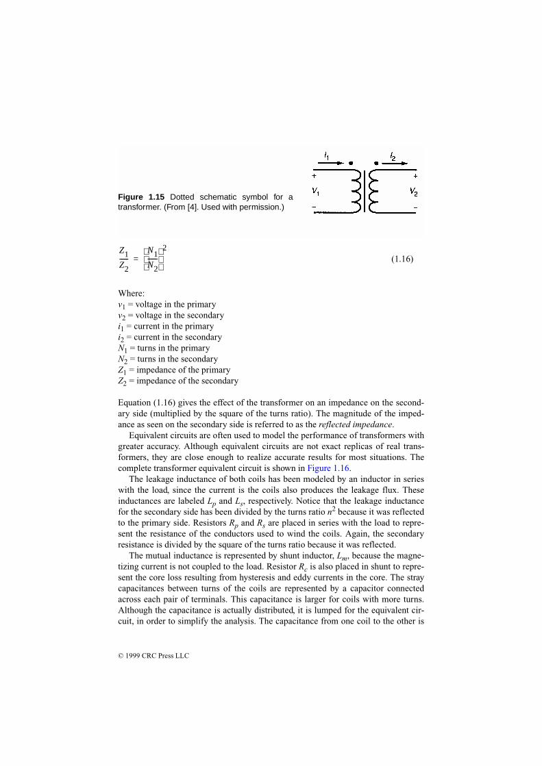
grams, a small dot is placed near one end of each coil, as shown in Figure 1.15. Thedot indicates a rise in voltage from the unmarked to the marked terminal on eachcoil. Under this convention, current into the dot on the primary side is labeled ashaving positive polarity, and current out of the dotted terminal on the other side isassigned positive polarity. This means that the power flow must be into the trans-former on one side, and out of the transformer on the other side.
1.4.5 The Ideal Transformer
Although no transformer is ideal in its characteristics, transformers approach theirideal characteristics in the operating range for which they were designed. The idealtransformer has no coil resistance and no core loses, so that it has no power loss [4].It also has no leakage inductance, because the permeability of the core is infinite,and the core material is able to carry an infinite amount of flux without saturating.Therefore, the mutual inductance is also infinite. The capacitance in an ideal trans-former is negligible. The equations for an ideal transformer are given as follows:
(1.13)
(1.14)
(1.15)
v1i1 v2i2=
v1v2-----
N1N2------=
i1i2----
N2N1------=
Figure 1.14 A typical magnetization curve.(From [4]. Used with permission.)
© 1999 CRC Press LLC
(1.16)
Where:v1 = voltage in the primaryv2 = voltage in the secondaryi1 = current in the primaryi2 = current in the secondaryN1 = turns in the primaryN2 = turns in the secondaryZ1 = impedance of the primaryZ2 = impedance of the secondary
Equation (1.16) gives the effect of the transformer on an impedance on the second-ary side (multiplied by the square of the turns ratio). The magnitude of the imped-ance as seen on the secondary side is referred to as the reflected impedance.
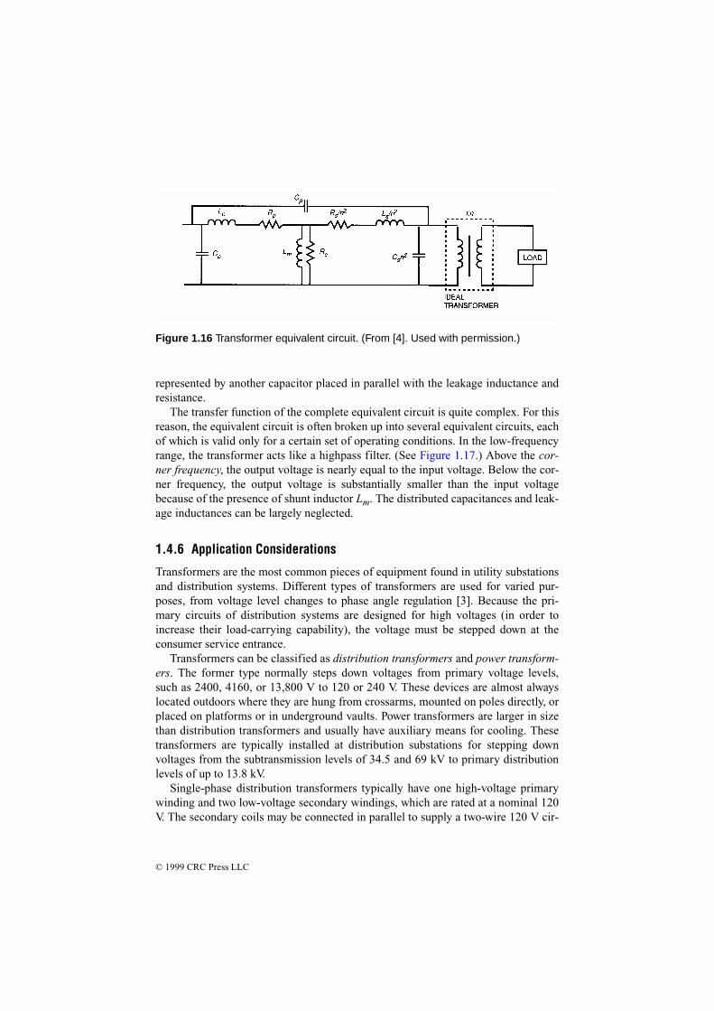
Equivalent circuits are often used to model the performance of transformers withgreater accuracy. Although equivalent circuits are not exact replicas of real trans-formers, they are close enough to realize accurate results for most situations. Thecomplete transformer equivalent circuit is shown in Figure 1.16.
The leakage inductance of both coils has been modeled by an inductor in serieswith the load, since the current is the coils also produces the leakage flux. Theseinductances are labeled Lp and Ls, respectively. Notice that the leakage inductancefor the secondary side has been divided by the turns ratio n2 because it was reflectedto the primary side. Resistors Rp and Rs are placed in series with the load to repre-sent the resistance of the conductors used to wind the coils. Again, the secondaryresistance is divided by the square of the turns ratio because it was reflected.
The mutual inductance is represented by shunt inductor, Lm, because the magne-tizing current is not coupled to the load. Resistor Rc is also placed in shunt to repre-sent the core loss resulting from hysteresis and eddy currents in the core. The straycapacitances between turns of the coils are represented by a capacitor connectedacross each pair of terminals. This capacitance is larger for coils with more turns.Although the capacitance is actually distributed, it is lumped for the equivalent cir-cuit, in order to simplify the analysis. The capacitance from one coil to the other is
Z1Z2------
N1N2------
2
=
Figure 1.15 Dotted schematic symbol for atransformer. (From [4]. Used with permission.)
© 1999 CRC Press LLC
represented by another capacitor placed in parallel with the leakage inductance andresistance.
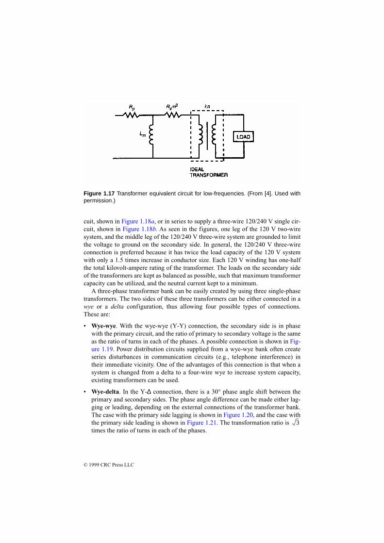
The transfer function of the complete equivalent circuit is quite complex. For thisreason, the equivalent circuit is often broken up into several equivalent circuits, eachof which is valid only for a certain set of operating conditions. In the low-frequencyrange, the transformer acts like a highpass filter. (See Figure 1.17.) Above the cor-ner frequency, the output voltage is nearly equal to the input voltage. Below the cor-ner frequency, the output voltage is substantially smaller than the input voltagebecause of the presence of shunt inductor Lm. The distributed capacitances and leak-age inductances can be largely neglected.
1.4.6 Application Considerations
Transformers are the most common pieces of equipment found in utility substationsand distribution systems. Different types of transformers are used for varied pur-poses, from voltage level changes to phase angle regulation [3]. Because the pri-mary circuits of distribution systems are designed for high voltages (in order toincrease their load-carrying capability), the voltage must be stepped down at theconsumer service entrance.
Transformers can be classified as distribution transformers and power transform-ers. The former type normally steps down voltages from primary voltage levels,such as 2400, 4160, or 13,800 V to 120 or 240 V. These devices are almost alwayslocated outdoors where they are hung from crossarms, mounted on poles directly, orplaced on platforms or in underground vaults. Power transformers are larger in sizethan distribution transformers and usually have auxiliary means for cooling. Thesetransformers are typically installed at distribution substations for stepping downvoltages from the subtransmission levels of 34.5 and 69 kV to primary distributionlevels of up to 13.8 kV.
Single-phase distribution transformers typically have one high-voltage primarywinding and two low-voltage secondary windings, which are rated at a nominal 120V. The secondary coils may be connected in parallel to supply a two-wire 120 V cir-
Figure 1.16 Transformer equivalent circuit. (From [4]. Used with permission.)
© 1999 CRC Press LLC
cuit, shown in Figure 1.18a, or in series to supply a three-wire 120/240 V single cir-cuit, shown in Figure 1.18b. As seen in the figures, one leg of the 120 V two-wiresystem, and the middle leg of the 120/240 V three-wire system are grounded to limitthe voltage to ground on the secondary side. In general, the 120/240 V three-wireconnection is preferred because it has twice the load capacity of the 120 V systemwith only a 1.5 times increase in conductor size. Each 120 V winding has one-halfthe total kilovolt-ampere rating of the transformer. The loads on the secondary sideof the transformers are kept as balanced as possible, such that maximum transformercapacity can be utilized, and the neutral current kept to a minimum.
A three-phase transformer bank can be easily created by using three single-phasetransformers. The two sides of these three transformers can be either connected in awye or a delta configuration, thus allowing four possible types of connections.These are:
• Wye-wye. With the wye-wye (Y-Y) connection, the secondary side is in phasewith the primary circuit, and the ratio of primary to secondary voltage is the sameas the ratio of turns in each of the phases. A possible connection is shown in Fig-ure 1.19. Power distribution circuits supplied from a wye-wye bank often createseries disturbances in communication circuits (e.g., telephone interference) intheir immediate vicinity. One of the advantages of this connection is that when asystem is changed from a delta to a four-wire wye to increase system capacity,existing transformers can be used.
• Wye-delta. In the Y-∆ connection, there is a 30° phase angle shift between theprimary and secondary sides. The phase angle difference can be made either lag-ging or leading, depending on the external connections of the transformer bank.The case with the primary side lagging is shown in Figure 1.20, and the case withthe primary side leading is shown in Figure 1.21. The transformation ratio is times the ratio of turns in each of the phases.
3
Figure 1.17 Transformer equivalent circuit for low-frequencies. (From [4]. Used withpermission.)

© 1999 CRC Press LLC
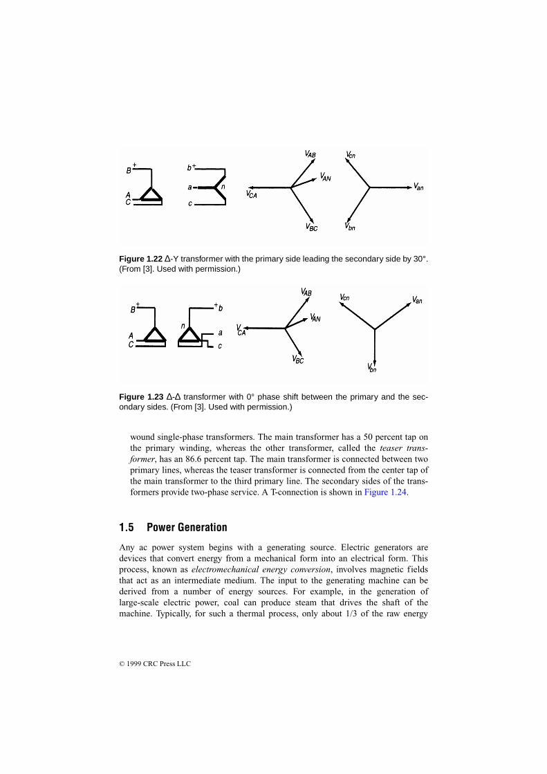
• Delta-wye. With the ∆-Y connection, the neutral of the secondary wye can begrounded and single-phase loads connected across the phase and the neutral con-ductor. Three-phase loads are connected across the phases. The phasor relation-ship between the primary and the secondary sides is shown in Figure 1.22. Thetransformation ratio is 1/ times the ratio of turns in each of the phases.
• Delta-delta. The ∆-∆ connection does not cause a phase shift between the pri-mary and the secondary sides. The phasor relationship of this transformer isshown in Figure 1.23. The transformation ratio is equal to the ratio of the turns ineach of the phases. There is no problem from third-harmonic overvoltage or tele-phone interference because such disturbances get trapped in the delta and do notpass into the lines.
Although these four configurations are the most common ones used, other arrange-ments are possible, including:
• Open-Delta. An advantage of the ∆-∆ connection is that if one of the sin-gle-phase transformers becomes damaged or is removed for maintenance, theremaining two can be operated in a so-called open-delta connection. Because thecurrents in each of the two remaining transformers are the same as the line cur-rent, each transformer carries times the current it was carrying in theclosed-delta connection. The open-delta bank continues to deliver three-phasecurrents and voltages in their correct phase relationship. To keep the transformersfrom being overloaded, however, it is necessary to reduce the line currents byapproximately 1/ .
3
3
3
(a) (b)
Figure 1.18 Connections for a single-phase distribution transformer: (a) parallel con-nection, (b) series connection. (From [3]. Used with permission.)

© 1999 CRC Press LLC
• Scott or T-Connection. The Scott or T-connection is used when a two-phase (ora transformed three-phase) supply is needed from a three-phase system. In gen-eral, the T-connection is used for deriving a three-phase transformation, and theScott connection is mainly used for obtaining a two-phase output. The two con-nections are similar in basic design. Either connection requires two specially
Figure 1.19 Y-Y transformer with 0° phase shift between the primary and the second-ary sides. (From [3]. Used with permission.)
Figure 1.20 Y-∆ transformer with the primary side lagging the secondary side by 30°.(From [3]. Used with permission.)
Figure 1.21 Y-∆ transformer with the primary side leading the secondary side by 30°.(From [3]. Used with permission.)
© 1999 CRC Press LLC
wound single-phase transformers. The main transformer has a 50 percent tap onthe primary winding, whereas the other transformer, called the teaser trans-former, has an 86.6 percent tap. The main transformer is connected between twoprimary lines, whereas the teaser transformer is connected from the center tap ofthe main transformer to the third primary line. The secondary sides of the trans-formers provide two-phase service. A T-connection is shown in Figure 1.24.
1.5 Power Generation
Any ac power system begins with a generating source. Electric generators aredevices that convert energy from a mechanical form into an electrical form. Thisprocess, known as electromechanical energy conversion, involves magnetic fieldsthat act as an intermediate medium. The input to the generating machine can bederived from a number of energy sources. For example, in the generation oflarge-scale electric power, coal can produce steam that drives the shaft of themachine. Typically, for such a thermal process, only about 1/3 of the raw energy
Figure 1.22 ∆-Y transformer with the primary side leading the secondary side by 30°.(From [3]. Used with permission.)
Figure 1.23 ∆-∆ transformer with 0° phase shift between the primary and the sec-ondary sides. (From [3]. Used with permission.)

© 1999 CRC Press LLC
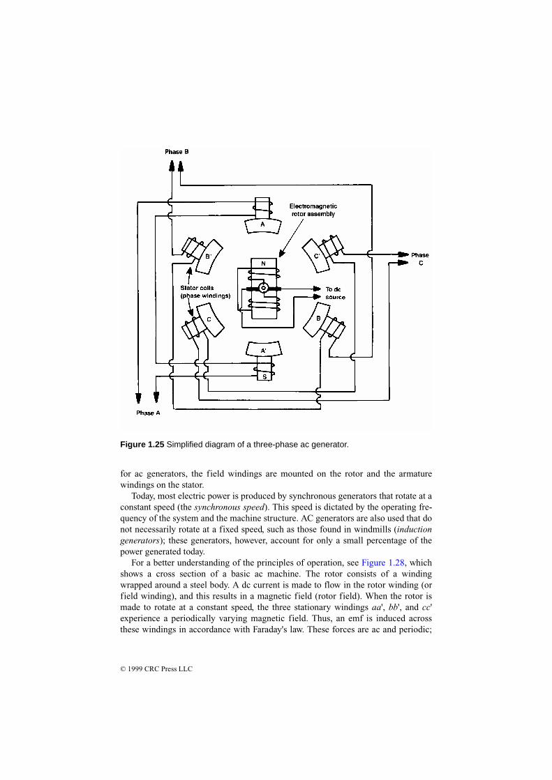
(i.e., from coal) is converted into mechanical energy. The final step of the energyconversion is quite efficient, with efficiency close to 100 percent.
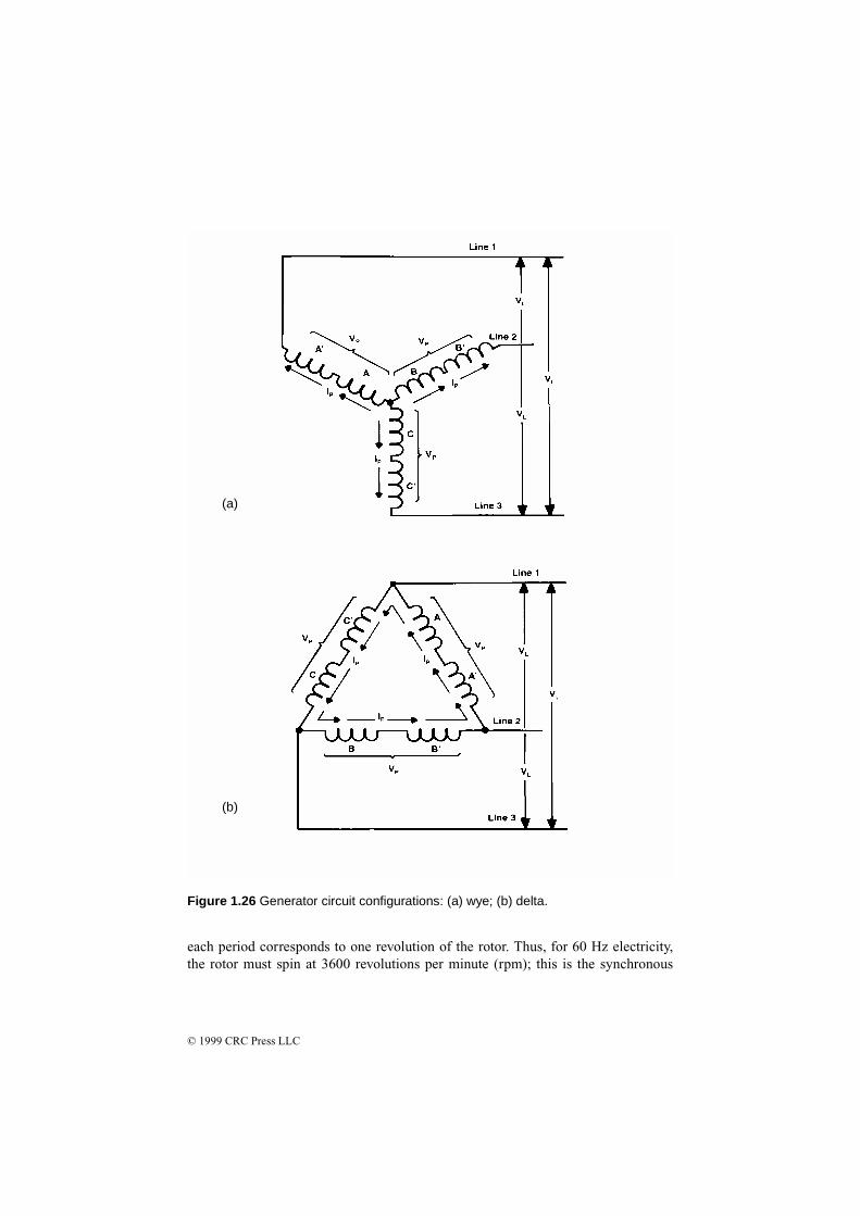
A simplified diagram of a three-phase generator is shown in Figure 1.25. Notethat poles A', B', and C' represent the start of each of the phase windings, whilepoles A, B, and C represent the ends of each of the windings. As with transformers,the windings of the generator can be connected in either of two ways:
• Wye configuration. A circuit arrangement in which the schematic diagram of thewindings form a Y.
• Delta configuration. A circuit arrangement in which the schematic diagram ofthe windings form a delta.
Figure 1.26 illustrates the connection arrangements.The generator shown in Figure 1.25 is a rotating-field type of device. A magnetic
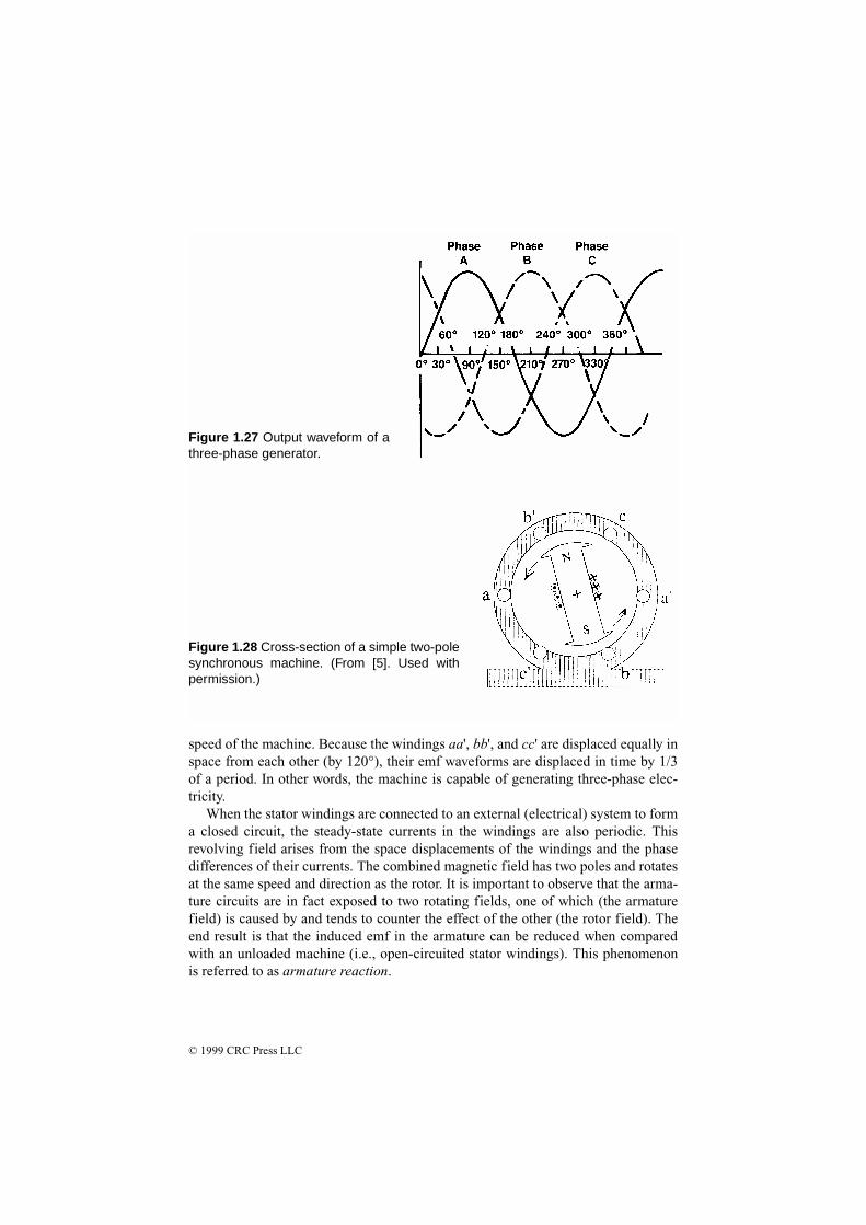
field is developed by an external dc voltage. Through electromagnetic induction, acurrent is induced into each of the stationary (stator) coils of the generator. Becauseeach of the phase windings is separated by 120°, the output voltage of the generatoralso is offset for each phase by 120° (Figure 1.27). Three-phase power is used almostexclusively for power distribution because it is an efficient method of transportingelectrical energy.
1.5.1 Fundamental Concepts
The operation of a generator is based on Faraday's law of electromagnetic induction[5]: if a coil (or winding) is linked to a varying magnetic field, then an electromotiveforce (or voltage) is induced across the coil. Thus, generators have two essentialparts: one that creates a magnetic field, and the other where the emf energies areinduced. The magnetic field is typically generated by electromagnets; thus, the fieldintensity can be adjusted for control purposes. These windings are referred to asfield windings or field circuits. The coils where the emf energies are induced arecalled armature windings or armature circuits. One of these two components is sta-tionary (the stator), and the other is a rotational part (the rotor) driven by an externaltorque. Conceptually, it is immaterial which of the two components is intended torotate because, in either case, the armature circuits always experience a varyingmagnetic field. However, practical considerations lead to the common design that
Figure 1.24 The T connection for athree-phase to two-phase transforma-tion. (From [3]. Used with permission.)
© 1999 CRC Press LLC
for ac generators, the field windings are mounted on the rotor and the armaturewindings on the stator.
Today, most electric power is produced by synchronous generators that rotate at aconstant speed (the synchronous speed). This speed is dictated by the operating fre-quency of the system and the machine structure. AC generators are also used that donot necessarily rotate at a fixed speed, such as those found in windmills (inductiongenerators); these generators, however, account for only a small percentage of thepower generated today.
For a better understanding of the principles of operation, see Figure 1.28, whichshows a cross section of a basic ac machine. The rotor consists of a windingwrapped around a steel body. A dc current is made to flow in the rotor winding (orfield winding), and this results in a magnetic field (rotor field). When the rotor ismade to rotate at a constant speed, the three stationary windings aa', bb', and cc'experience a periodically varying magnetic field. Thus, an emf is induced acrossthese windings in accordance with Faraday's law. These forces are ac and periodic;
Figure 1.25 Simplified diagram of a three-phase ac generator.
© 1999 CRC Press LLC
each period corresponds to one revolution of the rotor. Thus, for 60 Hz electricity,the rotor must spin at 3600 revolutions per minute (rpm); this is the synchronous
(a)
(b)
Figure 1.26 Generator circuit configurations: (a) wye; (b) delta.
© 1999 CRC Press LLC
speed of the machine. Because the windings aa', bb', and cc' are displaced equally inspace from each other (by 120°), their emf waveforms are displaced in time by 1/3of a period. In other words, the machine is capable of generating three-phase elec-tricity.
When the stator windings are connected to an external (electrical) system to forma closed circuit, the steady-state currents in the windings are also periodic. Thisrevolving field arises from the space displacements of the windings and the phasedifferences of their currents. The combined magnetic field has two poles and rotatesat the same speed and direction as the rotor. It is important to observe that the arma-ture circuits are in fact exposed to two rotating fields, one of which (the armaturefield) is caused by and tends to counter the effect of the other (the rotor field). Theend result is that the induced emf in the armature can be reduced when comparedwith an unloaded machine (i.e., open-circuited stator windings). This phenomenonis referred to as armature reaction.
Figure 1.27 Output waveform of athree-phase generator.
Figure 1.28 Cross-section of a simple two-polesynchronous machine. (From [5]. Used withpermission.)
© 1999 CRC Press LLC
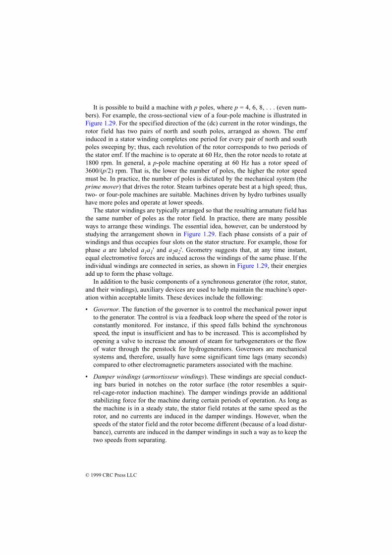
It is possible to build a machine with p poles, where p = 4, 6, 8, . . . (even num-bers). For example, the cross-sectional view of a four-pole machine is illustrated inFigure 1.29. For the specified direction of the (dc) current in the rotor windings, therotor field has two pairs of north and south poles, arranged as shown. The emfinduced in a stator winding completes one period for every pair of north and southpoles sweeping by; thus, each revolution of the rotor corresponds to two periods ofthe stator emf. If the machine is to operate at 60 Hz, then the rotor needs to rotate at1800 rpm. In general, a p-pole machine operating at 60 Hz has a rotor speed of3600/(p/2) rpm. That is, the lower the number of poles, the higher the rotor speedmust be. In practice, the number of poles is dictated by the mechanical system (theprime mover) that drives the rotor. Steam turbines operate best at a high speed; thus,two- or four-pole machines are suitable. Machines driven by hydro turbines usuallyhave more poles and operate at lower speeds.
The stator windings are typically arranged so that the resulting armature field hasthe same number of poles as the rotor field. In practice, there are many possibleways to arrange these windings. The essential idea, however, can be understood bystudying the arrangement shown in Figure 1.29. Each phase consists of a pair ofwindings and thus occupies four slots on the stator structure. For example, those forphase a are labeled a1a1' and a2a2'. Geometry suggests that, at any time instant,equal electromotive forces are induced across the windings of the same phase. If theindividual windings are connected in series, as shown in Figure 1.29, their energiesadd up to form the phase voltage.
In addition to the basic components of a synchronous generator (the rotor, stator,and their windings), auxiliary devices are used to help maintain the machine’s oper-ation within acceptable limits. These devices include the following:
• Governor. The function of the governor is to control the mechanical power inputto the generator. The control is via a feedback loop where the speed of the rotor isconstantly monitored. For instance, if this speed falls behind the synchronousspeed, the input is insufficient and has to be increased. This is accomplished byopening a valve to increase the amount of steam for turbogenerators or the flowof water through the penstock for hydrogenerators. Governors are mechanicalsystems and, therefore, usually have some significant time lags (many seconds)compared to other electromagnetic parameters associated with the machine.
• Damper windings (armortisseur windings). These windings are special conduct-ing bars buried in notches on the rotor surface (the rotor resembles a squir-rel-cage-rotor induction machine). The damper windings provide an additionalstabilizing force for the machine during certain periods of operation. As long asthe machine is in a steady state, the stator field rotates at the same speed as therotor, and no currents are induced in the damper windings. However, when thespeeds of the stator field and the rotor become different (because of a load distur-bance), currents are induced in the damper windings in such a way as to keep thetwo speeds from separating.

© 1999 CRC Press LLC
• Excitation control system. Modern excitation systems are fast and efficient. Anexcitation control system is a feedback loop designed to maintain the voltage atthe machine terminals at a set level. Figure 1.30 illustrates the mechanisms atwork. Assume that a disturbance occurs in the system, and as a result, themachine terminal voltage Vt drops. The excitation system boosts the internalvoltage EF. This action can increase the voltage Vt and also tends to increase thereactive power output.
From a system viewpoint, the two controlling mechanisms of excitation and thegovernor rely on local information (the machine terminal voltage and rotor speed).In other words, they are decentralized controls. For large-scale systems, suchdesigns do not always guarantee stable behavior because the effects of the intercon-nection system and other elements in the network are not taken into account. Ananalysis of the operation of centralized control systems is beyond the scope of thisbook; however, it is instructive to examine some of the principles of decentralizedcontrol systems. Many of these principles apply in a modified form to centralizedcontrol techniques.
1.5.1.1 Control Techniques
Reliable electric power service implies that the loads are fed at a constant voltageand frequency at all times [5]. A stable power system is one in which the synchro-nous machines, if perturbed, will return to their original state if there is no netchange in power, or stabilize at a new state without loss of synchronization. Themachine rotor angle is used to quantify stability; that is, if the difference in the angle
Figure 1.29 A four-pole synchronous machine: (a) cross-section of the machine; (b)schematic diagram for the phase a windings. (From [5]. Used with permission.)

© 1999 CRC Press LLC
between machines increases or oscillates for an extended period of time, the systemis considered unstable. The swing equation, given by
(1.17)
governs the motion of the machine rotor. J is moment of inertia, δm is mechanicaltorque angle with respect to a rotating reference, ωm is shaft angular velocity, and Tais the accelerating torque. Two factors that act as criteria for the stability of a gener-ating unit are the angular swing of the machine during and following fault condi-tions, and the time it takes to clear the transient swing.
The mechanical torque of the prime mover—steam or hydraulic—for a large gen-erator depends on rotor speed. In an unregulated machine, the torque speed charac-teristic is linear over the rated range of speeds. The prime mover speed of a machinewill drop in response to an increased load, and the valve position must be opened toincrease the speed of the machine. In a regulated machine (governor controlled), thespeed control mechanism controls the throttle valves to the steam turbine or the gateposition for a water turbine.
Automatic voltage regulation can be used to adjust the field winding current, thuschanging Eg as the load on the machine is varied (Figure 1.31). If the power outputof a generator is to be increased while an automatic voltage regulator holds the busvoltage at a constant value, then the field winding current must be increased. Themaximum voltage output of a machine is limited by the maximum voltage of theexcitor supplying the field winding. Figure 1.32 illustrates control of a power-gener-ating unit.
The performance of a transmission system can be improved by reactive compen-sation of a series or parallel type. Series compensation consists of banks of capaci-tors placed in series with each phase conductor of the line and is used to reduce theseries impedance of the line, which is the principal cause of voltage drop. Shunt
J J Tm m aδ ω= =
Figure 1.30 The per-phase equivalent circuit of a round-rotor synchronous machine. is the internal voltage (phasor form) and Vt is the terminal voltage.EF

© 1999 CRC Press LLC
compensation consists of inductors placed from each line to neutral and is used toreduce the shunt susceptance of the line.
1.5.2 Power Generating Systems
Electrical power can be produced in many ways, including chemical reactions, heat,light, or mechanical energy. Most electrical power produced today is through hydro-electric plants, nuclear energy, and by burning coal, oil, or natural gas. Fossil fueland nuclear-fission plants use steam turbines to deliver the mechanical energyrequired to rotate large three-phase generators, which produce massive quantities ofelectrical power. Generators used in such facilities usually are classified as high-speed units, operating at 3600 rpm to produce a 60 Hz output frequency. Hydroelec-
Figure 1.31 The basic power circuit of a generating system; . (From[5]. Used with permission.)
V E I Xs g a g= −
Figure 1.32 Block diagram of a generating control system. (From [5]. Used with per-mission.)
© 1999 CRC Press LLC
tric systems use hydraulic turbines, mounted vertically to intercept the flow of waterto produce electrical energy. Most hydroelectric facilities use low-speed generators,operating at from 120 to 900 rpm to produce 60 Hz. It follows that a larger numberof poles are required for a low-speed generator.
Fossil fuels, used as a source of heat, are burned to produce steam in a boiler sys-tem. The steam then drives one or more generators. Coal and coke are used com-monly to produce energy in this manner. Other fossil fuel sources include oil andnatural gas.
A nuclear power plant is basically a fossil fuel facility with a nuclear powersource to produce heat and then steam. Nuclear fission is a complex process thatresults in the division of the nucleus of an atom into two nuclei. This splitting of theatom is initiated by bombardment of the nucleus with neutrons, gamma rays, orother charged particles.
A hydroelectric system is the simplest of all power plants. Flowing water from areservoir is channeled through a control gate that directs water to the blades of ahydraulic turbine. The turbine, in turn, drives one or more generators. Although sim-ple in design and efficient in operation, hydroelectric systems are limited by theavailability of a water reservoir.
Concern about the burning of fossil fuels and the safety of nuclear power has ledto the development of alternative fuel sources for turbine-driven power plants.Power generating systems now in operation include:
• Geothermal systems, which utilize the heat of a molten mass in the interior of theearth to produce steam, which drives a turbine generator. Such systems are effi-cient and simple, but their placement is limited to areas of geothermal activity.
• Wind systems, which use a number of small generators mounted on supports andattached to propeller-type blades to intercept prevailing winds. Naturally, genera-tor output is determined by wind activity, limiting the use of these systems on anylarge scale.
Significant variations in load requirements must be satisfied at different times bya generating plant. Because of wide variations in load demands, much of the gener-ating capability of a facility may be unused during low-demand periods. Two math-ematical ratios commonly are used to measure utility service:
• Load factor. The average load for a given period divided by the peak load for thatsame period.
• Capacity factor. The average load for a given period divided by the output capac-ity of the power plant.
Under ideal conditions, both the load factor and the capacity factor are unity (100percent). Commercial power systems use a number of three-phase generators con-nected in parallel, and synchronized in phase, to supply the load requirements.
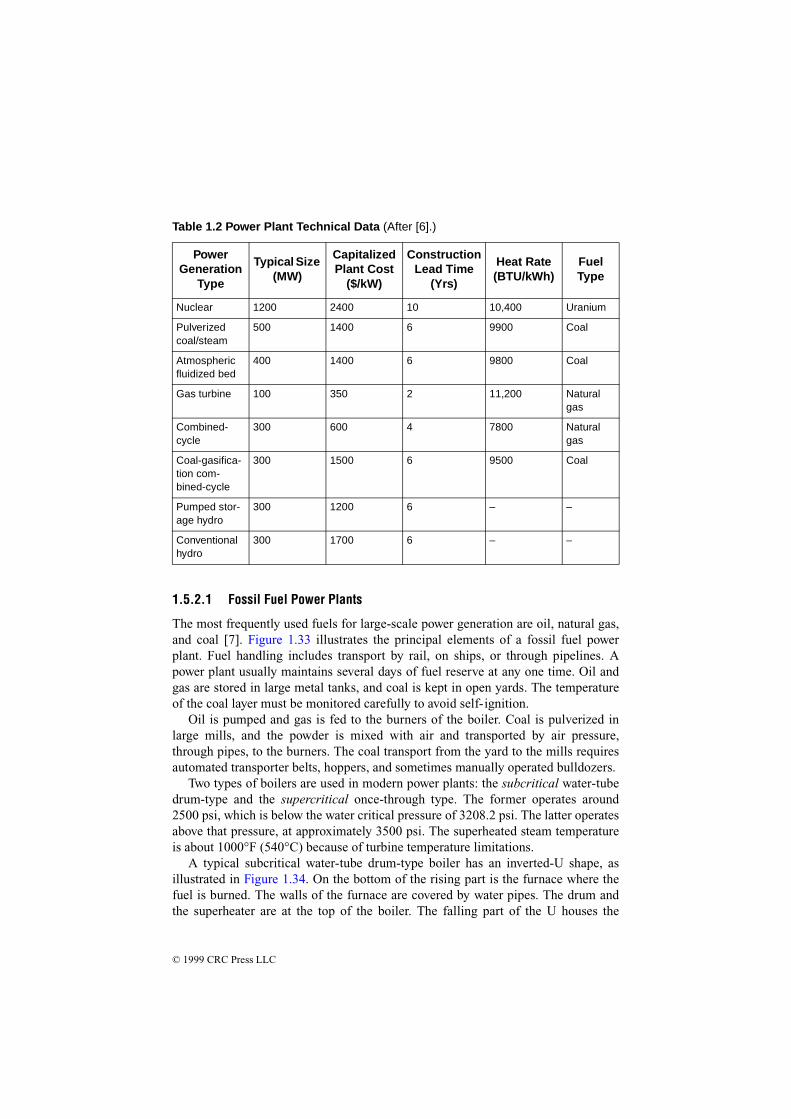
Table 1.2 lists general technical details for different types of common powerplants.
© 1999 CRC Press LLC
1.5.2.1 Fossil Fuel Power Plants
The most frequently used fuels for large-scale power generation are oil, natural gas,and coal [7]. Figure 1.33 illustrates the principal elements of a fossil fuel powerplant. Fuel handling includes transport by rail, on ships, or through pipelines. Apower plant usually maintains several days of fuel reserve at any one time. Oil andgas are stored in large metal tanks, and coal is kept in open yards. The temperatureof the coal layer must be monitored carefully to avoid self-ignition.
Oil is pumped and gas is fed to the burners of the boiler. Coal is pulverized inlarge mills, and the powder is mixed with air and transported by air pressure,through pipes, to the burners. The coal transport from the yard to the mills requiresautomated transporter belts, hoppers, and sometimes manually operated bulldozers.
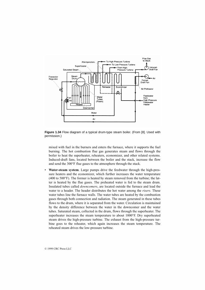
Two types of boilers are used in modern power plants: the subcritical water-tubedrum-type and the supercritical once-through type. The former operates around2500 psi, which is below the water critical pressure of 3208.2 psi. The latter operatesabove that pressure, at approximately 3500 psi. The superheated steam temperatureis about 1000°F (540°C) because of turbine temperature limitations.
A typical subcritical water-tube drum-type boiler has an inverted-U shape, asillustrated in Figure 1.34. On the bottom of the rising part is the furnace where thefuel is burned. The walls of the furnace are covered by water pipes. The drum andthe superheater are at the top of the boiler. The falling part of the U houses the
Table 1.2 Power Plant Technical Data (After [6].)
Power Generation
Type
Typical Size (MW)
Capitalized Plant Cost
($/kW)
Construction Lead Time
(Yrs)
Heat Rate (BTU/kWh)
Fuel Type
Nuclear 1200 2400 10 10,400 Uranium
Pulverized coal/steam
500 1400 6 9900 Coal
Atmospheric fluidized bed
400 1400 6 9800 Coal
Gas turbine 100 350 2 11,200 Natural gas
Combined-cycle
300 600 4 7800 Natural gas
Coal-gasifica-tion com-bined-cycle
300 1500 6 9500 Coal
Pumped stor-age hydro
300 1200 6 – –
Conventional hydro
300 1700 6 – –

© 1999 CRC Press LLC
reheaters, economizer (water heater), and air preheater, which is supplied by theforced-draft fan. The induced-draft fan forces the flue gases out of the system andsends them up the stack, which is located behind the boiler. This steam generator hasthree major systems:
• Fuel system. Fuel is mixed with air and injected into the furnace through burn-ers. The burners are equipped with nozzles, which are supplied by preheated airand carefully designed to assure the optimum air-fuel mix. The fuel mix isignited by oil or gas torches. The furnace temperature is around 3000°F.
• Air-flue gas system. Ambient air is driven by the forced-draft fan through the airpreheater, which is heated by the high-temperature (600°F) flue gases. The air is
(a)
(b)
Figure 1.33 Primary components of a fossil fuel power plant: (a) system block dia-gram; (b) common configuration of turbine/generator system. (Drawing a from [7].Used with permission. Drawing b from [14]. Used with permission.)
© 1999 CRC Press LLC
mixed with fuel in the burners and enters the furnace, where it supports the fuelburning. The hot combustion flue gas generates steam and flows through theboiler to heat the superheater, reheaters, economizer, and other related systems.Induced-draft fans, located between the boiler and the stack, increase the flowand send the 300°F flue gases to the atmosphere through the stack.
• Water-steam system. Large pumps drive the feedwater through the high-pres-sure heaters and the economizer, which further increases the water temperature(400 to 500°F). The former is heated by steam removed from the turbine; the lat-ter is heated by the flue gases. The preheated water is fed to the steam drum.Insulated tubes called downcomers, are located outside the furnace and lead thewater to a header. The header distributes the hot water among the risers. Thesewater tubes line the furnace walls. The water tubes are heated by the combustiongases through both connection and radiation. The steam generated in these tubesflows to the drum, where it is separated from the water. Circulation is maintainedby the density difference between the water in the downcomer and the watertubes. Saturated steam, collected in the drum, flows through the superheater. Thesuperheater increases the steam temperature to about 1000°F. Dry superheatedsteam drives the high-pressure turbine. The exhaust from the high-pressure tur-bine goes to the reheater, which again increases the steam temperature. Thereheated steam drives the low-pressure turbine.
Figure 1.34 Flow diagram of a typical drum-type steam boiler. (From [8]. Used withpermission.)

© 1999 CRC Press LLC
The typical supercritical once-through-type boiler concept is shown in Figure 1.35.The feedwater enters through the economizer to the boiler, which consists of risertubes that line the furnace wall. All the water is converted to steam and fed directlyto the superheater. The latter increases the steam temperature above the critical tem-perature of the water and drives the turbine. The construction of these steam genera-tors is more expensive than the drum-type units but has a higher overall operatingefficiency.
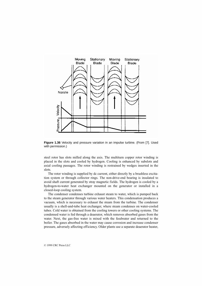
The turbine converts the heat energy of the steam into mechanical energy. Mod-ern power plants typically use one high-pressure and one or two lower-pressure tur-bines. High-pressure steam enters the high-pressure turbine to flow through anddrive the turbine. The exhaust is reheated in the boiler and returned to thelower-pressure units. Both the rotor and the stationary part of the turbine haveblades. The length of the blades increases from the steam entrance to the exhaust.Figure 1.36 shows the blade arrangement of an impulse-type turbine. Steam entersthrough nozzles and flows through the first set of moving rotor blades. The follow-ing stationary blades change the direction of the flow and direct the steam into thenext set of moving blades. The nozzles increase the steam speed and reduce pres-sure, as shown in the figure. The impact of the high-speed steam, generated by thechange of direction and speed in the moving blades, drives the turbine.
In a fossil fuel plant, the generator converts mechanical energy from the turbinesinto electrical energy. The stator typically has a laminated and slotted silicon steeliron core. The stacked core is clamped and held together by insulated axial throughbolts. The stator winding is placed in the slots and consists of a copper-strand con-figuration with woven glass insulation between the strands and mica flakes, micamat, or mica paper ground-wall insulation. To avoid insulation damage caused byvibration, the groundwall insulation is reinforced by asphalt, epoxy-impregnatedfiberglass, or Dacron. Most frequently, the stator is hydrogen-cooled; however,small units may be air-cooled and very large units may be water-cooled. The solid
Figure 1.35 Block diagram of a once-through-type steam generator. (From[7]. Used with permission.)
© 1999 CRC Press LLC
steel rotor has slots milled along the axis. The multiturn copper rotor winding isplaced in the slots and cooled by hydrogen. Cooling is enhanced by subslots andaxial cooling passages. The rotor winding is restrained by wedges inserted in theslots.
The rotor winding is supplied by dc current, either directly by a brushless excita-tion system or through collector rings. The non-drive-end bearing is insulated toavoid shaft current generated by stray magnetic fields. The hydrogen is cooled by ahydrogen-to-water heat exchanger mounted on the generator or installed in aclosed-loop cooling system.
The condenser condenses turbine exhaust steam to water, which is pumped backto the steam generator through various water heaters. This condensation produces avacuum, which is necessary to exhaust the steam from the turbine. The condenserusually is a shell-and-tube heat exchanger, where steam condenses on water-cooledtubes. Cold water is obtained from the cooling towers or other cooling systems. Thecondensed water is fed through a deaerator, which removes absorbed gases from thewater. Next, the gas-free water is mixed with the feedwater and returned to theboiler. The gases absorbed in the water may cause corrosion and increase condenserpressure, adversely affecting efficiency. Older plants use a separate deaerator heater,
Figure 1.36 Velocity and pressure variation in an impulse turbine. (From [7]. Usedwith permission.)

© 1999 CRC Press LLC
while deaerators in modern plants are usually integrated in the condenser, whereinjected steam jets produce a pressure drop and remove absorbed gases.
1.5.2.2 Nuclear Power Plants
More than 500 nuclear power plants currently operate around the world [7]. Close to300 operate pressurized water reactors (PWRs), more than 100 are built with boil-ing-water reactors (BWRs), about 50 use gas-cooled reactors, and the rest areheavy-water reactors. In addition, a few fast breeder reactors are in operation.These reactors are built for better utilization of uranium fuel. The modern nuclearplant size varies from 100 to 1200 MW.
The general arrangement of a PWR power plant is shown in Figure 1.37a. Thereactor heats the water from about 550 to approximately 650°F. High pressure, atabout 2235 psi, prevents boiling. Pressure is maintained by a pressurizer, and thewater is circulated by a pump through a heat exchanger. The heat exchanger evapo-rates the feedwater and generates steam, which supplies a system similar to a con-ventional power plant. The advantage of this two-loop system is the separation ofthe potentially radioactive reactor cooling fluid from the water-steam system.
The reactor core consists of fuel and control rods. Grids hold both the control andfuel rods. The fuel rods are inserted in the grid following a predetermined pattern.The fuel elements are Zircaloy-clad rods filled with UO2 pellets. The control rodsare made of a silver, cadmium, and indium alloy protected by stainless steel. Thereactor operation is controlled by the position of the rods. In addition, control rodsare used to shut down the reactor. The rods are released and fall in the core whenemergency shutdown is required. Cooling water enters the reactor from the bottom,flows through the core, and is heated by nuclear fission.
In the BWR, shown in Figures 1.37b and 1.38, the pressure is low (about 1000psi). The nuclear reaction heats the water directly to evaporate it and produce wet
(a) (b)
Figure 1.37 Types of nuclear power plants: (a) pressurized water reactor; (b) boiling-water reactor. (From [7]. Used with permission.)

© 1999 CRC Press LLC
steam at about 545°F. The remaining water is recirculated and mixed with feedwa-ter. The steam drives a turbine that typically rotates at 1800 rpm. The rest of theplant is similar to a conventional power plant. Figure 1.38 shows all the major com-ponents of the reactor. The fuel and control rod assembly is located in the lower part.The steam separators are above the core, and the steam dryers are at the top of thereactor. The reactor is enclosed by a concrete dome.
Figure 1.38 Typical configuration of a boiling-water reactor. (Courtesy of GeneralElectric Company.)

© 1999 CRC Press LLC
1.5.2.3 Hydroelectric Power Plants
Hydroelectric power plants convert energy produced by a water head into electricenergy [7]. The head is produced by building a dam across a river, which forms theupper-level reservoir. In the case of low head, the water forming the reservoir is fedto the turbine through the intake channel or the turbine is integrated in the dam. Thelatter arrangement is shown in Figure 1.39. Penstock tubes or tunnels are used formedium-head and high-head plants, as shown in Figures 1.40 and 1.41, respectively.The spillway regulates the excess water in the reservoir by opening gates at the bot-tom of the dam or permitting overflow on the spillway section of the dam. The waterdischarged from the turbine flows to the lower or tail water reservoir, which is usu-ally a continuation of the original water channel.
High-head plants are built with impulse turbines, where the head-generated waterpressure is converted into velocity by nozzles and the high-velocity water jets drivethe turbine runner. Low- and medium-head installations are built with reaction-typeturbines, where the water pressure is mostly converted to velocity in the turbine. Thetwo basic classes of reaction turbines are the propeller or Kaplan type, mostly usedfor low-head plants, and the Francis type, primarily used for medium-head plants.The cross section of a typical low-head Kaplan turbine is shown in Figure 1.42.
The vertical shaft turbine and generator are supported by a thrust bearingimmersed in oil. The generator is in the upper, watertight chamber. The turbine run-ner has 4 to 10 propeller types, and adjustable-pitch blades. The blades are regulatedfrom 5 to 35º degrees by an oil-pressure-operated servomechanism. The water isevenly distributed along the periphery of the runner by a concrete spiral case andregulated by adjustable wicket blades. The water is discharged from the turbinethrough an elbow-shaped draft tube. The conical profile of the tube reduces thewater speed from the discharge speed of 10 to 30 ft/s to 1 ft/s to increase turbine effi-ciency.
The hydrogenerator is a low-speed (usually 120 to 360 rpm) salient-pole machinewith a vertical shaft. The typical number of poles ranges from 20 to 72. They are
Figure 1.39 Low-head hydroelectric powerplant. (From [8]. Used with permission.)

© 1999 CRC Press LLC
mounted on a pole spider, which is a welded, spoked wheel. The spider is mountedon the forged steel shaft. The poles are built with a laminated iron core and strandedcopper winding. Damper bars are built in the pole faces. The stator is built with aslotted, laminated iron core that is supported by a welded steel frame. Windings aremade of stranded conductors insulated between the turns by fiberglass or Dacron-glass. The ground insulation is formed from multiple layers of mica tape impreg-nated with epoxy or polyester resins. Older machines use asphalt and mica tapeinsulation, which is sensitive to corona-discharge-caused insulation deterioration.Direct water-cooling is used for very large machines, while the smaller ones are air-or hydrogen-cooled. Some machines use forced-air cooling with an air-to-water heatexchanger. A braking system is installed in larger machines to stop the generatorrapidly when necessary.
1.6 Capacitors
A capacitor consists, basically, of two conductors separated by a dielectric. Theoperation of a capacitor in a circuit is dependent upon its ability to charge and dis-charge. When a capacitor charges, an excess of electrons is accumulated on oneplate, and a deficiency of electrons is created on the other plate. Capacitance is
Figure 1.40 Medium-headhydroelectric power plant.(From [8]. Used with permis-sion.)

© 1999 CRC Press LLC
determined by the size of the conductive material (the plates) and their separation(determined by the type and thickness of the dielectric material). Capacitance isdirectly proportional to plate size and inversely proportional to the distance betweenthe plates. The unit of capacitance is the farad (F). A capacitance of 1 F results whena potential of 1 V causes an electric charge of 1 coulomb to accumulate on a capaci-tor.
The value of a parallel-plate capacitor can be found from
(1.18)
Where:C = capacitance (F)
Cx N A
d=
−× −ε [ ( ) ]1
10 13
Figure 1.41 High-head hydroelectric power plant. (From [8]. Used with permission.)

© 1999 CRC Press LLC
ε = dielectric constant of the insulationd = spacing between the platesN = number of platesA = area of the platesx = 0.0885 when A nand d are in centimeters
The work necessary to transport a unit charge from one plate to another is
e = k g (1.19)
Where:e = volts expressing energy per unit chargeg = colombs of charge already transported
Figure 1.42 Typical low-head hydroelectric power plant with a Kaplan turbine. (From[8]. Used with permission.)
© 1999 CRC Press LLC
k = proportionality factor between the work necessary to carry a unit charge betweenthe two plates and the charge already transported
The latter quantity (k)is equal to 1/C, where C is the capacitance in F.The value of a capacitor can now be calculated from
(1.20)
Where q= charge (C) and e is found from Equation (1.19).
The energy stored in a capacitor is
(1.21)
Where:W = energy (J)C = capacitance (F)V = applied voltage (V)
If a direct current is applied to a capacitor, the device will charge to the value ofthe applied voltage. After the capacitor is fully charged, it will block the flow ofdirect current. However, if an ac voltage is applied, the changing value of currentwill cause the device to alternately charge and discharge. In a purely capacitive cir-cuit, the situation shown in Figure 1.43 will exist. The greatest amount of currentwill flow when the voltage changes most rapidly; that point occurs at the 0° and180° positions in the sine wave where the polarity reverses. At these positions, max-imum current is developed in the circuit, as shown. It is evident by studying thewaveform that, in a purely capacitive circuit, voltage will lag current by 90°.Because all practical circuits contain some resistance, a lag of 0° to 90° may beexperienced in practice. Figure 1.44 illustrates a case in which voltage lags currentby 30º.
Because of the electrostatic field developed around a capacitor, an opposition tothe flow of alternating current exists. This opposition is known as capacitive reac-tance:
(1.22)
Where:Xc = capacitive reactance (Ω)2 π R = the mathematical expression of one sine wave
Cqe---=
WCV
2
2----------=
Xc1
2πfC-------------=

© 1999 CRC Press LLC
f = frequency (Hz)C = capacitance (F)
The dielectric used for a given capacitor varies, depending upon the application.Common dielectrics include air, gas, mica, glass, and ceramic. Each has a differentdielectric constant, temperature range, and thickness.
(a)
(b)
(c)
Figure 1.43 A purely capacitive circuit: (a) circuit diagram; (b) representative wave-forms; (c) vector representation.

© 1999 CRC Press LLC
The dielectric constant of a material determines the electrostatic energy that maybe stored in that material per unit volume for a given voltage. The value of thedieleectric constant expresses the ratio of a capacitor whose dielectric is a vacuum toone using a given dielectric material. The dielectric constant of air is 1, the referenceunit employed for characterizing this parameter. As the dielectric constant is
(a)
(b)
(c)
Figure 1.44 A resistive-capacitive circuit: (a) circuit diagram; (b) representativewaveforms; (c) vector representation.

© 1999 CRC Press LLC
increased or decreased, the capacitance will increase or decrease, respectively. Table1.3 lists the dielectric constants of various common materials.
The dielectric constant of most materials is affected by both temperature and fre-quency, except for quartz, Styrofoam, and Teflon, whose dielectric constants remainessentially constant.
In addition to capacitance, a practical capacitor has inductance and resistancecomponents, as shown in Figure 1.45. The stray components are identified as fol-lows:
• Rs = series resistance of wire leads, contact terminations, and electrodes
• Rp = shunt resistance resulting from the resistivity of the dielectric and casematerial, and dielectric losses
• L = stray inductance resulting from the leads and the electrodes
The equivalent series resistance (ESR) of a capacitor is the ac resistance of thedevice, reflecting both the series resistance (Rs) and the parallel resistance (Rp) at agiven frequency. This parameter permits the loss resulting from the foregoing ele-ments to be expressed as a loss in a single resistor in the equivalent circuit.
The power factor (PF) of a capacitor defines the electrical losses in the deviceoperating under an ac voltage. In an ideal device, the current will lead the appliedvoltage by 90°. A practical capacitor, because of its dielectric, electrode, and contacttermination losses, exhibits a phase angle of less than 90°. The power factor of a
Table 1.3 Comparison of Capacitor Dielectric Constants (After [10].)
Dielectric K (Dielectric Constant)
Air or vacuum 1.0
Paper 2.0 – 6.0
Plastic 2.1 – 6.0
Mineral oil 2.2 – 2.3
Silicone oil 2.7 – 2.8
Quartz 3.8 – 4.4
Glass 4.8 – 8.0
Porcelain 5.1 – 5.9
Mica 5.4 – 8.7
Aluminum oxide 8.4
Tantalum pentoxide 26
Ceramic 12 – 400,000

© 1999 CRC Press LLC
capacitor is defined as the ratio of the effective series resistance to the impedance ofthe capacitor. PF usually is expressed as a percentage.
The quality factor (Q) of a capacitor is the ratio of the capacitor reactance to theresistance of the device at a specified frequency. The Q is determined by the equa-tion
(1.23)
(1.24)
Where:Q = quality factorf = frequency (Hz)C = value of capacitance (F)R = internal resistance (Ω)PF = power factor
Other important specifications for capacitors include:
• Dielectric absorption (DA): The reluctance of the dielectric to give up storedelectrons when the capacitor is discharged. This is often called memory becauseif a capacitor is discharged through a resistance and the resistance is removed, theelectrons that remain in the dielectric will reconvene on the electrode, causing avoltage to appear across the capacitor. DA is usually measured by charging thecapacitor for 5 min., discharging it for 5 s, then having an open circuit for 1 minafter which the recovery voltage is read. The percentage of DA is defined as theratio of recovery voltage to charging voltage times 100.
• Dissipation factor (DF): The ratio of the effective series resistance to capacitivereactance. DF normally is expressed as a percentage.
Q1
2πfCR-----------------=
Q1
PF-------=
Figure 1.45 The equivalent circuit of a capacitor.

© 1999 CRC Press LLC
• Leakage current: The current flowing through the capacitor when a dc voltage isapplied.
• Insulation resistance: The ratio of the applied voltage to the leakage current.Insulation resistance is normally expressed in megohms.
• Ripple current/voltage: The rms value of the maximum allowable alternating cur-rent or voltage (superimposed on any dc level) at a specific frequency at whichthe capacitor may be operated continuously at a specified temperature.
• Surge voltage: The maximum operating voltage of the capacitor at any tempera-ture.
The properties of common discrete capacitors are given in Table 1.4. Note that ofthe types listed, only ceramic, paper, oil, and vacuum are typically used for high-voltage operation (applied potentials above 1 kV).
1.7 Transmission Circuits
The heart of any utility power-distribution system is the cable used to tie distantparts of the network together. Conductors are rated by the American Wire Gauge(AWG) scale. The smallest is no. 36, and the largest is no. 0000. There are 40 sizesin between. Sizes larger than no. 0000 AWG are specified in thousand circular milunits, referred to as “MCM” units (M is the Roman numeral expression for 1000).The cross-sectional area of a conductor doubles with each increase of three AWGsizes. The diameter doubles with every six AWG sizes.
Most conductors used for power transmission are made of copper or aluminum.Copper is the most common. Stranded conductors are used where flexibility isrequired. Stranded cables usually are more durable than solid conductor cables ofthe same AWG size. For long distances, utilities typically use uninsulated aluminumconductors or aluminum conductor steel-reinforced cables. For shorter distances,insulated copper wire normally is used.
Ampacity is the measure of the ability of a conductor to carry electric current.Although all metals will conduct current to some extent, certain metals are moreefficient than others. The three most common high-conductivity conductors are:
• Silver, with a resistivity of 9.8 Ω/circular mil-ft
• Copper, with a resistivity of 10.4 Ω/circular mil-ft
• Aluminum, with a resistivity of 17.0 Ω/circular mil-ft
The ampacity of a conductor is determined by the type of material used, the cross-sectional area, and the heat-dissipation effects of the operating environment. Con-ductors operating in free air will dissipate heat more readily than conductors placedin a larger cable or in a raceway with other conductors will. Table 1.5 lists the prin-cipal parameters of common wire sizes.
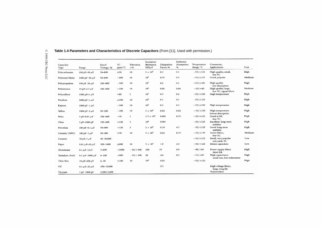
© 1999 C
RC
Press L
LC
Table 1.4 Parameters and Characteristics of Discrete Capacitors (From [11]. Used with permission.)

© 1999 CRC Press LLC
1.7.1 Types of Conductors
Wire and cable designed for use in a power-distribution system can be roughlydivided into two categories:
• Overhead conductors
• Underground cables
Each will be examined in the following sections.
Table 1.5 Characteristics of Copper Wire
Wire Size (AWG)
Diameter (mils)
Circular Mil Area
Ohms/1000 ft (20ºC)
Current Carrying
Capacity at 700 C.M./A
Diameter (mm)
1 289.3 83,690 0.1239 119.6 7.348
2 257.6 66,370 0.1563 94.8 6.544
3 229.5 52,640 0.1970 75.2 5.827
4 204.3 41,740 0.2485 59.6 5.189
5 181.9 33,100 0.3133 47.3 4.621
6 162.0 26,250 0.3951 37.5 4.115
7 144.3 20,820 0.4902 29.7 3.665
8 128.5 16,510 0.6282 23.6 3.264
9 114.4 13,090 0.7921 18.7 2.906
10 101.9 10,380 0.9989 14.8 2.588
11 90.7 8,234 1.260 11.8 2.305
12 80.8 6,530 1.588 9.33 2.053
13 72.0 5,178 2.003 7.40 1.828
14 64.1 4,107 2.525 5.87 1.628
15 57.1 3,257 3.184 4.65 1.450
16 50.8 2,583 4.016 3.69 1.291
17 45.3 2,048 5.064 2.93 1.150
18 40.3 1,624 6.385 2.32 1.024
19 35.9 1,288 8.051 1.84 0.912
20 32.0 1,022 10.15 1.46 0.812
21 28.5 810 12.80 1.16 0.723
22 25.3 642 16.14 0.918 0.644

© 1999 CRC Press LLC
1.7.1.1 Overhead Cables
Many different types of conductors are used on overhead distribution lines [3]. Theyvary in both size and number, depending on the voltage level and the type of circuit.Copper, aluminum, and steel are the most commonly used materials for overheadlines. Copper is used in three forms: hard drawn, medium-hard drawn, and softdrawn or annealed. Hard-drawn copper has the greatest strength and is used for cir-cuits of relatively long spans (200 ft or more). However, its inflexibility makes itharder to work with. The soft-drawn variety is the weakest of the copper conductors.Its use is limited to short spans. The medium-hard-drawn copper conductor hasfound widespread use in medium-range distribution circuits.
Steel wire is only about one-tenth as good a conductor as copper and, hence, israrely used alone. However, it offers an economic advantage over the other types ofconductors. Also, because steel wire is much stronger than copper, it permits longerspans and requires fewer supports.
Aluminum is only 60 to 80 percent as good a conductor as copper and only halfas strong as copper. However, its property of lighter weight, as compared to copperand steel, and its relative advantage in transmitting ac power because of reducedskin effect, makes it suitable for overhead lines. Usually, the aluminum wires arestranded on a core of steel wire to form what is termed an aluminum conductorssteel reinforced (ACSR) conductor. The more strands in the ACSR conductor, thegreater flexibility it will have. Hence, the larger conductors used today are allstranded and twisted in layers concentrically around a central steel wire.
Table 1.6 lists the characteristics of various conductors that are typically used onoverhead distribution lines.
1.7.1.2 Underground Cables
Underground construction of distribution lines is designed mostly for urban areasand is dictated by economics, congestion, and density of population [3]. Althoughoverhead lines have been ordinarily considered to be less expensive and easier tomaintain, developments in underground cable and construction technology havenarrowed the cost gap to the point where such systems are competitive in manyurban and suburban residential installations.
The conductors used underground are different from overhead lines in that theyare insulated for their entire length and several of them may be combined under oneprotective sheath. The whole assembly is called an electric cable. These cables areeither buried directly in the ground, or they may be installed in ducts buried in theground. The conductors in cables are usually made of copper or aluminum and areusually stranded. They are made of soft-drawn copper because they do not have tosupport any weight. Cables can be either single conductor or multiple conductorsenclosed in a single sheath for economy.

© 1999 CRC Press LLC
1.7.1.3 Skin Effect
The effective resistance offered by a conductor to high frequencies is considerablygreater than the ohmic resistance measured with direct currents. This is because ofan action known as the skin effect, which causes the currents to be concentrated incertain parts of the conductor and leaves the remainder of the cross section to con-tribute little toward carrying the applied current.
When a conductor carries an alternating current, a magnetic field is produced thatsurrounds the wire. This field continually is expanding and contracting as the ac cur-rent wave increases from zero to its maximum positive value and back to zero, thenthrough its negative half-cycle. The changing magnetic lines of force cutting theconductor induce a voltage in the conductor in a direction that tends to retard thenormal flow of current in the wire. This effect is more pronounced at the center ofthe conductor. Thus, current within the conductor tends to flow more easily towardthe surface of the wire. The higher the frequency, the greater the tendency for cur-rent to flow at the surface. The depth of current flow is a function of frequency, andis determined from the following equation:
(1.25)d2.6
µf---------=
Table 1.6 General Characteristics of Overhead Conductors (After [12].)
Conductor Type Resistance (Ω/mi) Diameter (in) Amperes
1,000,000 AA 0.105 1.15 698
556,500 ACSR 0.186 0.927 730
500,000 AA 0.206 0.813 483
336,400 ACSR 0.306 0.721 530
4/0 ACSR 0.592 0.563 340
2/0 AA 0.769 0.414 230
1/0 ACSR 1.120 0.398 230
1/0 CU 0.607 0.368 310
#2 AA 1.540 0.292 156
#2 ACSR 1.690 0.316 180
#4 ACSR 2.550 0.257 140
#10 CU 5.903 0.102 80
#12 CU 9.375 0.081 75
#14 CU 14.872 0.064 2
© 1999 CRC Press LLC
Where:d = depth of current in milsµ = permeability (copper = 1, steel = 300)f = frequency of signal in MHz
It can be calculated that at a frequency of 100 Khz, current flow penetrates a con-ductor by 8 mils. At 1 MHz, the skin effect causes current to travel in only the top2.6 mils in copper, and even less in almost all other conductors. Therefore, the seriesimpedance of conductors at high frequencies is significantly higher than at low fre-quencies. Figure 1.46 shows the distribution of current in a radial conductor.
When a circuit is operating at high frequencies, the skin effect causes the currentto be redistributed over the conductor cross section in such a way as to make most ofthe current flow where it is encircled by the smallest number of flux lines. This gen-eral principle controls the distribution of current regardless of the shape of the con-ductor involved. With a flat-strip conductor, the current flows primarily along theedges, where it is surrounded by the smallest amount of flux.
It is evident from Equation 1.25 that the skin effect is minimal at power line fre-quencies for copper conductors. For steel conductors at high current, however, skineffect considerations are often important.
1.7.2 Dielectrics and Insulators
Dielectrics are materials that are used primarily to isolate components electricallyfrom each other or ground or to act as capacitive elements in devices, circuits, andsystems [13]. The insulating properties of dielectrics are directly attributable to theirlarge energy gap between the highest filled valence band and the conduction band.The number of electrons in the conduction band is extremely low because theenergy gap of a dielectric (5 to 7 eV) is sufficiently large to maintain most of theelectrons trapped in the lower band. As a consequence, a dielectric subjected to anelectric field will allow only an extremely small conduction or loss current. Thiscurrent will be caused by the following:
• The finite number of free electrons available
• Other free charge carriers (ions) typically associated with contamination by elec-trolytic impurities
• Dipole orientation losses arising with polar molecules under ac conditions
Often the two latter effects will tend to obscure the miniscule contribution of the rel-atively few free electrons available. Unlike solids and liquids, vacuum and gases (intheir nonionized state) approach the conditions of a perfect insulator—i.e., theyexhibit virtually no detectable loss or leakage current.
Two fundamental parameters that characterize a dielectric material are its con-ductivity σ and the value of the real permittivity or dielectric constant ε'. By defini-

© 1999 CRC Press LLC
tion, σ is equal to the ratio of the leakage current density Jl to the applied electricfield E
(1.26)
Because Jl is in A cm–2 and E is in V cm–1, the corresponding units of σ are in Scm–1 or Ω–1 cm–1.
Under ac conditions, dielectric losses arise mainly from the movement of freecharge carriers (electrons and ions), space charge polarization, and dipole orienta-tion. Ionic, space charge, and dipole losses are temperature and frequency depen-dent, a dependency that is reflected in the measured values of σ and ε'. Thisnecessitates the introduction of a complex permittivity ε defined by ε = ε´ – jε´´,where ε" is the imaginary value of the permittivity.
As the voltage is increased across a dielectric material, a point is ultimatelyreached beyond which the insulation will no longer be capable of sustaining any fur-ther rise in voltage and breakdown will ensue, causing a short-circuit to developbetween the electrodes. If the dielectric consists of a gas or liquid medium, thebreakdown will be self-healing in the sense that the gas or liquid will support anew areapplication of voltage. In a solid dielectric, however, the initial breakdown willresult in a formation of a permanent conductive channel, which cannot support areapplication of full voltage.
The breakdown strength of a dielectric under dc and impulse conditions tends toexceed that at ac fields, thereby suggesting the ac breakdown process is partially of a
σ =J
El
Figure 1.46 The skin effect on a conductor.

© 1999 CRC Press LLC
thermal nature. An additional factor, which may lower the ac breakdown strength, isthat associated with the occurrence of partial discharges either in void inclusions orat the electrode edges. This leads to breakdown values much less than the intrinsicvalue. In practice, breakdown values are generally of an extrinsic nature, and theintrinsic values are useful conceptually insofar as they provide an idea of an uppervalue that can be attained only under ideal conditions.
All insulating materials will undergo varying degrees of aging or deteriorationunder normal operating conditions. The rate of aging will be contingent upon themagnitude of the electrical, thermal, and mechanical stresses to which the materialis subjected. It will also be influenced by the composition and molecular structure ofthe material itself, as well as the chemical, physical, and radiation environmentunder which the material must operate. The useful life of an insulating system will,thus, be determined by a given set and subset of aging variables. For example, thesubset of variables in the voltage stress variable are the average and maximum val-ues of the applied voltage, its frequency, and the recurrence rate of superposedimpulse or transient voltage surges. For the thermal stress, the upper and lowerambient temperatures, the temperature gradient in the insulation, and the maximumpermissible operating temperature constitute the subvariable set. In addition, thecharacter of the mechanical stress will differ, depending upon whether torsion, com-pression, or tension and bending are involved. Furthermore, the aging rate will bedifferently affected if all stresses (electrical, thermal, and mechanical) act simulta-neously, separately, or in some predetermined sequence. The influence exerted onthe aging rate by the environment will depend on whether the insulation system willbe subjected to corrosive chemicals, petroleum fluids, water or high humidity, air oroxygen, ultraviolet radiation from the sun, and nuclear radiation. Organic insula-tions, in particular, may experience chemical degradation in the presence of oxygen.For example, polyethylene under temperature cycle will undergo both physical andchemical changes. These effects will be particularly acute at high operating temper-atures (90 to 130°C). At these temperatures, partial or complete melting of the poly-mer will occur and the increased diffusion rate will permit the oxygen to migrate toa greater depth into the polymer. Ultimately, the antioxidant will be consumed,resulting in an embrittlement of the polymer and, in extreme cases, in the formationof macroscopic cracks. Subjection of the polymer to many repeated overload cycleswill be accompanied by repeated melting and recrystallization of the polymer—aprocess that will inevitably cause the formation of cavities, which, when subjected tosufficiently high voltages, will undergo discharge, leading eventually to electricalbreakdown.
The 60 Hz breakdown strength of a 1 cm gap of air at 25°C at atmospheric pres-sure is 31.7 kV cm–1. Although this is a relatively low value, air is a most usefulinsulating medium for large electrode separations, as is the case for overhead trans-mission lines. The only dielectric losses in the overhead lines are those resultingfrom corona discharges at the line conductor surfaces and leakage losses over theinsulator surfaces. In addition, the highly reduced capacitance between the conduc-

© 1999 CRC Press LLC
tors of the lines ensures a small capacitance per unit length, thus rendering overheadlines an efficient means for transmitting large amounts of power over long distances.
1.7.2.1 Insulating Liquids
Insulating liquids are rarely used by themselves. Rather, they are intended for usemainly as impregnants with cellulose or synthetic papers [13]. The 60-Hz break-down strength of practical insulating liquids exceeds that of gases; for a 1-cm gapseparation, it is of the order of about 100 kV cm–1. However, because the breakdownstrength increases with decreasing gap length and as the oils are normally evaluatedusing a gap separation of 0.254 cm, the breakdown strengths normally cited rangefrom approximately 138 to 240 kV cm–1 (Table 1.7). The breakdown values aremore influenced by the moisture and particle contents of the fluids than by theirmolecular structure.
Mineral oils have been extensively used in high-voltage electrical apparatus sincethe turn of the century. They constitute a category of hydrocarbon liquids that areobtained by refining crude petroleum. Their composition consists of parafffinic,naphthenic, and aromatic constituents and is dependent upon the source of the crudeas well as the refining procedure followed. The inclusion of the aromatic constitu-ents is desirable because of their gas absorption and oxidation characteristics. Min-eral oils used for cable and transformer applications have low polar moleculecontents and are characterized by dielectric constants extending from about 2.10 to2.25, with dissipation factors generally between 2 × 10⁻⁵and 6 × 10⁻⁵ at room tem-perature, depending upon their viscosity and molecular weight. Their dissipationfactors increase appreciably at higher temperatures when the viscosities are reduced.Oils may deteriorate in service because of oxidation and moisture absorption.
Alkyl benzenes are used as impregnants in high-voltage cables, often as substi-tutes for the low-viscosity mineral oils in self-contained, oil-filled cables. The elec-trical properties of alkyl benzenes are comparable to those of mineral oils, and theyexhibit good gas inhibition characteristics. Because of their detergent character,alkyl benzenes tend to be more susceptible to contamination than mineral oils.
Since the discontinued use of the nonflammable polychlorinated biphenyls(PCBs), a number of unsaturated synthetic liquids have been developed for use inhigh-voltage capacitors, where, because of high stresses, evolved gases can readilyundergo partial discharge. Most of these new synthetic capacitor fluids are, thus,gas-absorbing, low-molecular-weight derivatives of benzene, with permittivitiesranging from 2.66 to 5.25 at room temperature (compared to 3.5 for PCBs). None ofthese fluids have the nonflammable characteristics of the PCBs; however, they dohave high boiling points.
Silicone liquids consist of polymeric chains of silicon atoms alternating withoxygen atoms, and with methyl side groups. For electrical applications, polydimeth-ylsiloxane fluids are used, primarily in transformers as substitutes for the PCBsbecause of their inherently high flash and flammability points, and reduced environ-mental concerns.

© 1999 CRC Press LLC
1.7.2.2 Insulating Solids
Solid insulating materials can be classified into two main categories: organic andinorganic [13]. There are a large number of solid inorganic insulants available,including the following:
• Alumina, produced by heating aluminum hydroxide or oxyhydroxide; it is widelyused as a filler for ceramic insulators. Further heating yields the corundum struc-ture, which in its sapphire form is used for dielectric substrates in microcircuitapplications.
• Porcelain, a multiphase ceramic material that is obtained by heating aluminumsilicates until a mullite phase is formed. Because mullite is porous, its surfacemust be glazed with a high-melting-point glass to render it smooth and impervi-ous to contaminants for use in overhead line insulators.
• Electrical-grade glasses, which tend to be relatively lossy at high temperatures.At low temperatures, however, they are suitable for use in overhead line insula-tors and in transformer, capacitor, and circuit breaker bushings. At high tempera-tures, their main application lies with incandescent and fluorescent lamps as wellas electronic tube envelopes.
Table 1.7 Electrical Properties of Common Insulating Liquids (From [13]. Used with permission.)
LiquidViscosity cSt
(37.8°C)
Dielectric Constant (at 60 Hz, 25°C)
Dissipation Factor (at 60 Hz, 100°C)
Breakdown Strength
(kV cm–1)
Capacitor oil 21 2.2 0.001 >118
Pipe cable oil 170 2.15 0.001 >118
Self-contained cable oil
49.7 2.3 0.001 >118
Heavy cable oil 2365 2.23 0.001 >118
Transformer oil 9.75 2.25 0.001 >128
Alkyl benzene 6.0 2.1 0.0004 >138
Polybutene pipe cable oil
110 (SUS) 2.14 (at 1 MHz) 0.0003 >138
Polybutene capacitor oil
2200 (SUS at 100°C)
2.22 (at 1 MHz) 0.0005 >138
Silicone fluid 50 2.7 0.00015 >138
Castor oil 98 (100°C) 3.74 0.06 >138
C8F16O fluoro-
carbon
0.64 1.86 <0.0005 >138

© 1999 CRC Press LLC
• Mica, a layer-type dielectric (mica films are obtained by splitting mica blocks).The extended two-dimensionally layered strata of mica prevents the formation ofconductive pathways across the substance, resulting in a high dielectric strength.It has excellent thermal stability and, because of its inorganic nature, is highlyresistant to partial discharges. It is used in sheet, plate, and tape forms in rotatingmachines and transformer coils.
Solid organic dielectrics consist of large polymer molecules, which generallyhave molecular weights in excess of 600. Primarily (with the notable exception ofpaper, which consists of cellulose that is comprised of a series of glucose units),organic dielectric materials are synthetically derived. Some of the more commoninsulating materials of this type include:
• Polyethylene (PE), perhaps one of the most common solid dielectrics. PE isextensively used as a solid dielectric extruded insulator in power and communi-cation cables. Linear PE is classified as a low- (0.910 to 0.925), medium- (0.926to 0.940), or high- (0.941 to 0.965) density polymer. Most of the PE used onextruded cables is of the cross-linked polyethylene type.
• Ethylene-propylene rubber (EPR), an amorphous elastomer that is synthesizedfrom ethylene and propylene. It is used as an extrudent on cables where its com-position has a filler content that usually exceeds 50 percent (comprising primarilyclay, with smaller amounts of added silicate and carbon black). Dielectric lossesare appreciably enhanced by the fillers, and, consequently, EPR is not suitable forextra-high-voltage applications. Its use is primarily confined to intermediate volt-ages (<69 kV) and to applications where high cable flexibility (due to its inherentrubber properties) may be required.
• Polypropylene, which has a structure related to that of ethylene with one addedmethyl group. It is a thermoplastic material having properties similar tohigh-density PE, although because of its lower density, polypropylene has also alower dielectric constant. Polypropylene has many electrical applications, both inbulk form as molded and extruded insulations, as well as in film form in tapedcapacitor, transformer, and cable insulations.
• Epoxy resins, which are characterized by low shrinkage and high mechanicalstrength. They can also be reinforced with glass fibers and mixed with micaflakes. Epoxy resins have many applications, including insulation of bars in thestators of rotating machines, solid-type transformers, and spacers for com-pressed-gas-insulated busbars and cables.
Impregnated-paper insulation is one of the earliest insulating systems employedin electrical power apparatus and cables. Although many current designs use solid-or compressed-gas insulating systems, the impregnated-paper approach still consti-tutes one of the most reliable insulating techniques available. Proper impregnationof the paper results in a cavity-free insulating system, thereby eliminating the occur-rence of partial discharges that inevitably lead to deterioration and breakdown of the

© 1999 CRC Press LLC
insulating system. The liquid impregnants employed are either mineral oils or syn-thetic fluids.
Low-density cellulose papers have slightly lower dielectric losses, but the dielec-tric breakdown strength is also reduced. The converse is true for impregnated sys-tems utilizing high-density papers. If the paper is heated beyond 200°C, thechemical structure of the paper breaks down, even in the absence of external oxy-gen, because the latter is readily available from within the cellulose molecule. Toprevent this process from occurring, cellulose papers are ordinarily not used at tem-peratures above 100°C.
1.7.3 Control and Switching Systems
Specialized hardware is necessary to interconnect the elements of a power-distribu-tion system. Utility control and switching systems operate under demanding condi-tions, including high voltage and current levels, exposure to lightning discharges,and 24-hour-a-day use. For reliable performance, large margins of safety must bebuilt into each element of the system. The primary control and switching elementsare high-voltage switches and protection devices.
High-voltage switches are used to manage the distribution network. Most discon-nect switches function to isolate failures or otherwise reconfigure the network. Air-type switches are typically larger versions of the common “knife switch” device. Toprevent arcing, air switches are changed only when power is removed from the cir-cuit. These types of switches can be motor driven or manually operated.
Oil-filled circuit breakers are used at substations to interrupt current when theline is hot. The contacts usually are immersed in oil to minimize arcing. Oil-filledcircuit breakers are available for operation at 500 kV and higher. Magnetic airbreakers are used primarily for low-voltage indoor applications.
Protection devices include fuses and lightning arresters. Depending upon theoperating voltage, various types of fuses can be used. Arc suppression is an essentialconsideration in the design and operation of a high-voltage fuse. A method must beprovided to extinguish the arc that develops when the fuse element begins to open.Lightning arresters are placed at numerous points in a power-distribution system.Connected between power-carrying conductors and ground, they are designed tooperate rapidly and repeatedly if necessary. Arresters prevent flashover faultsbetween power lines and surge-induced transformer and capacitor failures. Thedevices are designed to extinguish rapidly, after the lightning discharge has beendissipated, to prevent power follow-on damage to system components.
A fault in an electrical power system is the unintentional and undesirable creationof a conducting path (a short-circuit) or a blockage of current (an open-circuit) [14].The short-circuit fault is typically the most common and is usually implied whenmost people use the term “fault”. The causes of faults include lightning, wind dam-age, trees falling across lines, vehicles colliding with towers or poles, birds shortingout lines, aircraft colliding with lines, vandalism, small animals entering switchgear,
© 1999 CRC Press LLC
and line breaks resulting from excessive ice loading. Power system faults can be cat-egorized as one of four types:
• Single line-to-ground
• Line-to-line
• Double line-to-ground
• Balanced three-phase
The first three types constitute severe unbalanced operating conditions.It is important to determine the values of system voltages and currents during
fault conditions so that protective devices can be set to detect and minimize theirharmful effects. The time constants of the associated transients are such that sinuso-idal steady-state methods can typically be used.
High-voltage insulators permit all of the foregoing hardware to be reliably inter-connected. Most insulators are made of porcelain. The mechanical and electricaldemands placed on high-voltage insulators are stringent. When exposed to rain orsnow, the devices must hold off high voltages. They also must support the weight ofheavy conductors and other components.
1.7.3.1 Fault Protection Devices
Fuses are designed to melt and disconnect the circuit within which they are placedshould the current in the circuit increase above a specified thermal rating [3]. Fusesdesigned to be used in circuits operating above 600 V are classified as fuse cutouts.Oil-filled cutouts are mainly used in underground installations and contain the fus-ible elements in an oil-filled tank. Expulsion-type cutouts are the most commondevices used on overhead primary feeders. In this class of device, the melting of thefusible element causes heating of a fiber fuse tube, which, in turn, produces deioniz-ing gases to extinguish the arc. Expulsion-type cutouts are classified as:
• Open-fuse cutouts
• Enclosed-fuse cutouts
• Open-link-fuse cutouts
The automatic recloser is an overcurrent device that automatically trips andrecloses a preset number of times to clear or isolate faults. The concept of reclosingis derived from the fact that most utility system faults are temporary in nature andcan be cleared by de-energizing the circuit for a short period of time. Reclosers canbe set for a number of operation sequences, depending on the action desired. Thesetypically include instantaneous trip and reclose operation followed by a sequence oftime-delayed trip operations prior to lockout of the recloser. The minimum pick-upfor most reclosers is typically set to trip instantaneously at two times the nominalcurrent rating.

© 1999 CRC Press LLC
An automatic line recloser is constructed of an interrupting chamber and therelated contacts that operate in oil, a control mechanism to trigger tripping andreclosing, an operator integrator, and a lockout mechanism. An operating rod isactuated by a solenoid plunger that opens and closes the contacts in oil. Both sin-gle-phase and three-phase units are available.
The line sectionalizer is yet another overcurrent device. It is installed in conjunc-tion with backup circuit breakers or reclosers. The line sectionalizer maintains coor-dination with the backup interrupting device and is designed to open after a presetnumber of tripping operations of the backup element. Line sectionalizers areinstalled on poles or crossarms in overhead distribution systems. The standard con-tinuous current rating for sectionalizers range from 10 to 600 A. Sectionalizers alsoare available for both single-phase and three-phase systems.
The function of a circuit breaker is to protect a circuit from the harmful effects ofa fault, in addition to energizing and de-energizing the same circuit during normaloperation. Breakers are generally installed on both the incoming subtransmissionlines and the outgoing primary feeders of a utility substation. These devices aredesigned to operate as quickly as possible (less than 10 cycles of the power fre-quency) to limit the impact of a fault on the distribution and control system. At thesame time, the arc that forms between the opening contacts must be quenched rap-idly. Several schemes are available to extinguish the arc, the most common beingimmersion of the contacts in oil. Some circuit breakers have no oil, but quench thearc by a blast of compressed air. These are referred to as air circuit breakers. Yetanother type encloses the contacts in a vacuum or a gas, such as sulfur hexafluoride(SF6).
Air circuit breakers are typically used when fault currents are relatively small.These devices are characteristically simple, low cost, and require little maintenance.The fault current flows through coils creating a magnetic field that tends to force thearc into ceramic chutes that stretch the arc, often with the aid of compressed air.When the arc is extinguished through vacuum, the breaker is referred to as a vacuumcircuit breaker. Because a vacuum cannot sustain an arc, it can be an effectivemedium for this application. However, owing to imperfections present in a practicalvacuum device, a small arc of short duration can be produced. The construction ofvacuum circuit breakers is simple, but the maintenance is usually more complexthan with other devices.
1.7.3.2 Lightning Arrester
A lightning arrester is a device that protects electrical apparatus from voltage surgescaused by lightning [3]. It provides a path over which the surge can pass to groundbefore it has the opportunity to pass through and damage equipment. A standardlightning arrester consists of an air gap in series with a resistive element. The resis-tive element is usually made of a material that allows a low-resistance path to thevoltage surge, but presents a high-resistance path to the flow of line energy duringnormal operation. This material is known as the valve element. Silicon carbide is a

© 1999 CRC Press LLC
common valve element material. The voltage surge causes a spark that jumps acrossthe air gap and passes through the resistive element to ground.
1.8 Utility AC Power System
The details of power distribution vary from one city or country to another, and fromone utility company to another, but the basics are the same. Figure 1.47 shows asimplified distribution network. Power from a generating station or distribution gridcomes into an area substation at 115 kV or higher. The substation consists of switch-ing systems, step-down transformers, fuses, circuit breakers, reclosers, monitors,and control equipment. The substation delivers output voltages of approximately 60kV to subtransmission circuits, which feed distribution substations. The substationsconvert the energy to approximately 12 kV and provide voltage regulation andswitching provisions that permit patching around a problem. The 12 kV lines powerpole- and surface-mounted transformers, which supply various voltages to individ-ual loads. Typical end-user voltage configurations include:
• 120/208 V wye
• 277/480 V wye
• 120/240 V single phase
• 480 V delta
The circuits feeding individual customer loads are referred to as the secondary sys-tem, while the primary system is the network upstream from the secondary (Figure1.47c). The secondary system originates at the distribution transformer and ends atthe consumer loads. Each secondary main may supply groups of customers. In someinstances, where service reliability is incorporated into the design, the secondarymains of several adjacent transformers may be connected through a fuse or arecloser. This is referred to as secondary banking. If an even higher service reliabil-ity factor is required, the secondary mains in an area can be connected in a mesh or anetwork, similar to the networking of the primary.
Fuses and circuit breakers are included at a number of points in the distributionsystem to minimize fault-caused interruptions of service. Ground-fault interrupters(GFIs) are also included at various points in the 12 kV system to open the circuit ifexcessive ground currents begin to flow on the monitored line. (GFIs are also knownas ground fault current interrupters, or GFCIs.) Reclosers may be included as partof overcurrent protection of the 12 kV lines. They will open the circuit if excessivecurrents are detected, and reclose after a preset length of time, as discussed in theprevious section.
In some areas, the actions of circuit breakers, pole-mounted switches, and reclos-ers are controlled by 2-way radio systems that allow status interrogation and switch-ing of the remotely located devices from a control center. Some utilities use thismethod sparingly; others make extensive use of it.

© 1999 CRC Press LLC
Depending on the geographic location, varying levels of lightning protection areincluded as part of the ac power-system design. Most service drop transformers (12kV to 208 V) have integral lightning arresters. In areas of severe lightning, a ground(or shield) wire is strung between the top insulators of each pole, diverting the light-ning to the ground wire, and away from the hot leads.
(a)
Figure 1.47 Simplified block diagram of a basic utility company power distributionsystem: (a) Overall network. The devices shown as fuses could be circuit breakers orreclosers. All circuits shown are three-phase. The capacitors perform power factorcorrection duty. (b) System terminology. (c, next page) Distinction between the pri-mary and secondary distribution systems. (b and c from [3]. Used with permission.)
(b)
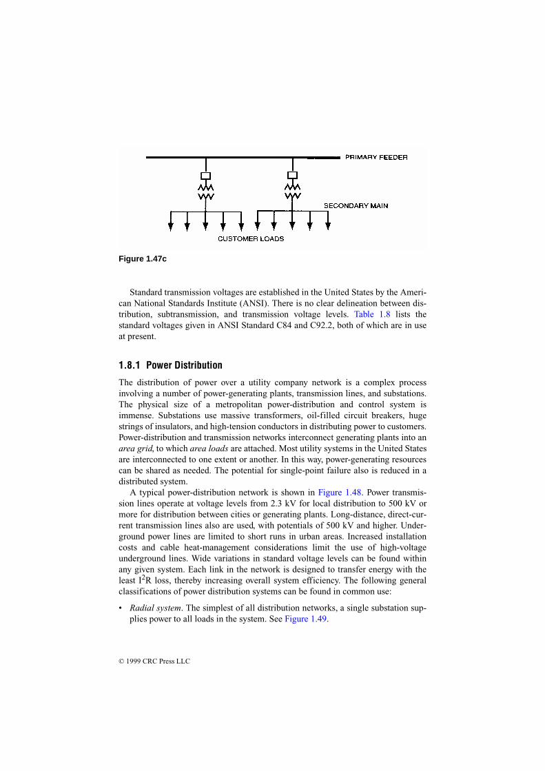
© 1999 CRC Press LLC
Standard transmission voltages are established in the United States by the Ameri-can National Standards Institute (ANSI). There is no clear delineation between dis-tribution, subtransmission, and transmission voltage levels. Table 1.8 lists thestandard voltages given in ANSI Standard C84 and C92.2, both of which are in useat present.
1.8.1 Power Distribution
The distribution of power over a utility company network is a complex processinvolving a number of power-generating plants, transmission lines, and substations.The physical size of a metropolitan power-distribution and control system isimmense. Substations use massive transformers, oil-filled circuit breakers, hugestrings of insulators, and high-tension conductors in distributing power to customers.Power-distribution and transmission networks interconnect generating plants into anarea grid, to which area loads are attached. Most utility systems in the United Statesare interconnected to one extent or another. In this way, power-generating resourcescan be shared as needed. The potential for single-point failure also is reduced in adistributed system.
A typical power-distribution network is shown in Figure 1.48. Power transmis-sion lines operate at voltage levels from 2.3 kV for local distribution to 500 kV ormore for distribution between cities or generating plants. Long-distance, direct-cur-rent transmission lines also are used, with potentials of 500 kV and higher. Under-ground power lines are limited to short runs in urban areas. Increased installationcosts and cable heat-management considerations limit the use of high-voltageunderground lines. Wide variations in standard voltage levels can be found withinany given system. Each link in the network is designed to transfer energy with theleast I2R loss, thereby increasing overall system efficiency. The following generalclassifications of power distribution systems can be found in common use:
• Radial system. The simplest of all distribution networks, a single substation sup-plies power to all loads in the system. See Figure 1.49.
Figure 1.47c
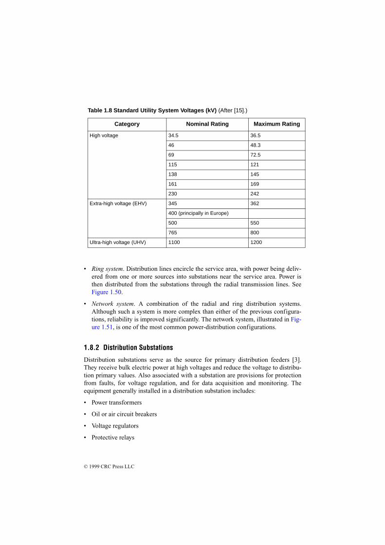
© 1999 CRC Press LLC
• Ring system. Distribution lines encircle the service area, with power being deliv-ered from one or more sources into substations near the service area. Power isthen distributed from the substations through the radial transmission lines. SeeFigure 1.50.
• Network system. A combination of the radial and ring distribution systems.Although such a system is more complex than either of the previous configura-tions, reliability is improved significantly. The network system, illustrated in Fig-ure 1.51, is one of the most common power-distribution configurations.
1.8.2 Distribution Substations
Distribution substations serve as the source for primary distribution feeders [3].They receive bulk electric power at high voltages and reduce the voltage to distribu-tion primary values. Also associated with a substation are provisions for protectionfrom faults, for voltage regulation, and for data acquisition and monitoring. Theequipment generally installed in a distribution substation includes:
• Power transformers
• Oil or air circuit breakers
• Voltage regulators
• Protective relays
Table 1.8 Standard Utility System Voltages (kV) (After [15].)
Category Nominal Rating Maximum Rating
High voltage 34.5 36.5
46 48.3
69 72.5
115 121
138 145
161 169
230 242
Extra-high voltage (EHV) 345 362
400 (principally in Europe)
500 550
765 800
Ultra-high voltage (UHV) 1100 1200
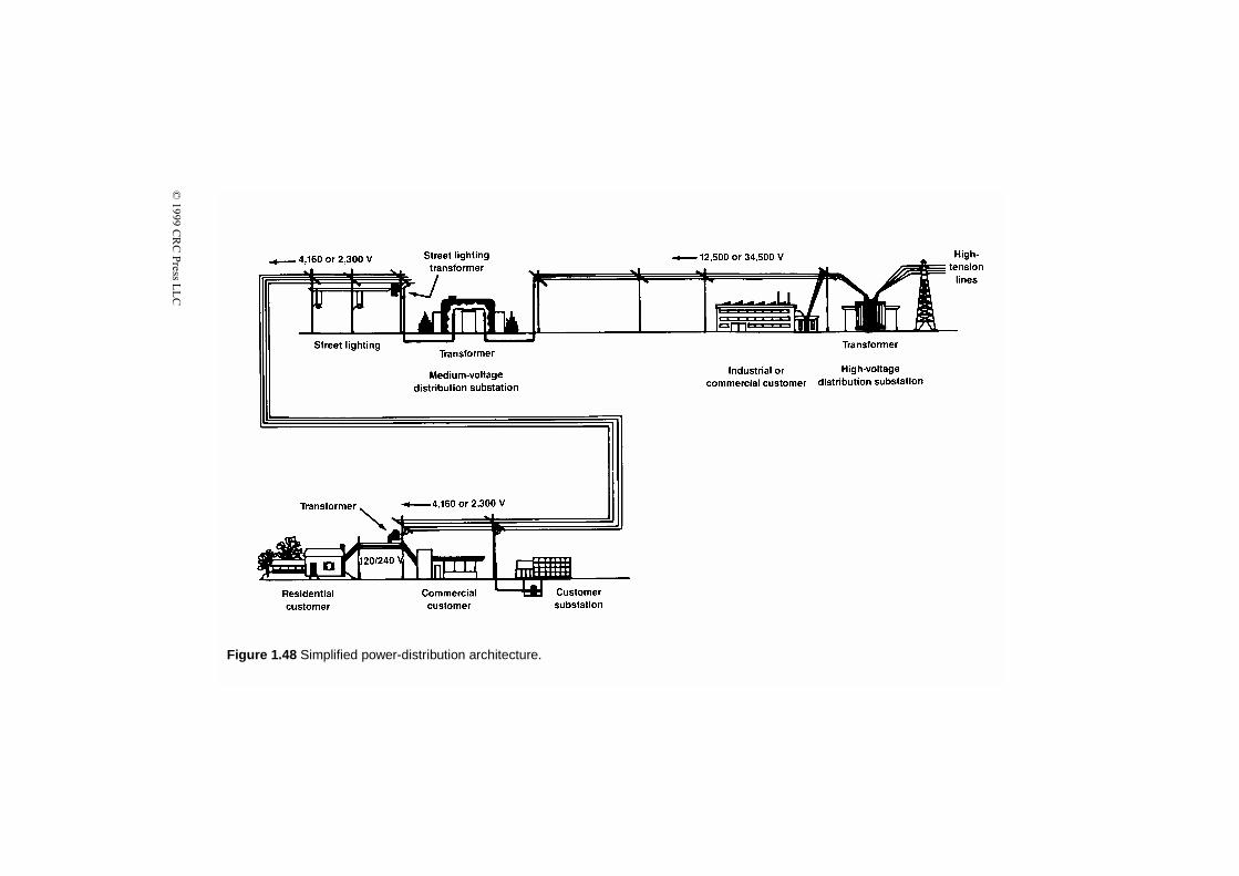
© 1999 C
RC
Press L
LC
Figure 1.48 Simplified power-distribution architecture.
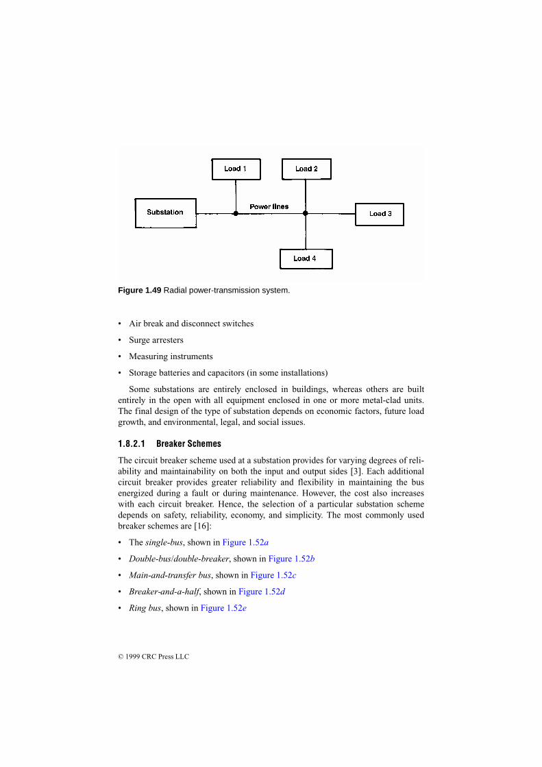
© 1999 CRC Press LLC
• Air break and disconnect switches
• Surge arresters
• Measuring instruments
• Storage batteries and capacitors (in some installations)
Some substations are entirely enclosed in buildings, whereas others are builtentirely in the open with all equipment enclosed in one or more metal-clad units.The final design of the type of substation depends on economic factors, future loadgrowth, and environmental, legal, and social issues.
1.8.2.1 Breaker Schemes
The circuit breaker scheme used at a substation provides for varying degrees of reli-ability and maintainability on both the input and output sides [3]. Each additionalcircuit breaker provides greater reliability and flexibility in maintaining the busenergized during a fault or during maintenance. However, the cost also increaseswith each circuit breaker. Hence, the selection of a particular substation schemedepends on safety, reliability, economy, and simplicity. The most commonly usedbreaker schemes are [16]:
• The single-bus, shown in Figure 1.52a
• Double-bus/double-breaker, shown in Figure 1.52b
• Main-and-transfer bus, shown in Figure 1.52c
• Breaker-and-a-half, shown in Figure 1.52d
• Ring bus, shown in Figure 1.52e
Figure 1.49 Radial power-transmission system.

© 1999 CRC Press LLC
Of these designs, the single-bus scheme costs the least; however, it possesses ratherlow reliability because the failure of the bus or any circuit breaker results in a totalshutdown of the substation. The most expensive arrangement is the double-bus/dou-ble-breaker scheme. Each circuit is provided with two circuit breakers, and thus, anybreaker can be taken out of service for maintenance without disruption of service atthe substation. In addition, feeder circuits can be connected to either bus. Themain-and-transfer bus requires an extra breaker for the bus tie between the main andthe auxiliary buses. The breaker-and-a-half scheme provides the most flexible oper-ation with high reliability. The relaying and automatic reclosing, however, are some-what complex.
Figure 1.50 Ring power-transmission system.
Figure 1.51 Network power-transmission system.

© 1999 CRC Press LLC
1.8.3 Voltage Analysis
Distribution systems are designed to maintain service voltages within specified lim-its during normal and emergency conditions. Typical voltage limits are [3]:
Figure 1.52 Substation bus and breaker arrangements: (a) single-bus; (b) double-bus/double-breaker; (c) main-and-transfer bus; (d) breaker-and-a-half; (e) ring bus.(From [3]. Used with permission.)
(a) (b) (c)
(d) (e)
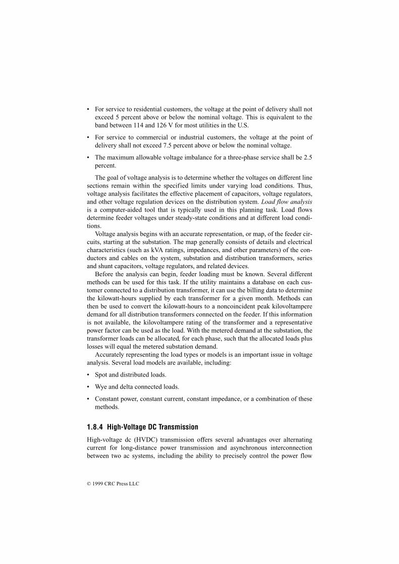
© 1999 CRC Press LLC
• For service to residential customers, the voltage at the point of delivery shall notexceed 5 percent above or below the nominal voltage. This is equivalent to theband between 114 and 126 V for most utilities in the U.S.
• For service to commercial or industrial customers, the voltage at the point ofdelivery shall not exceed 7.5 percent above or below the nominal voltage.
• The maximum allowable voltage imbalance for a three-phase service shall be 2.5percent.
The goal of voltage analysis is to determine whether the voltages on different linesections remain within the specified limits under varying load conditions. Thus,voltage analysis facilitates the effective placement of capacitors, voltage regulators,and other voltage regulation devices on the distribution system. Load flow analysisis a computer-aided tool that is typically used in this planning task. Load flowsdetermine feeder voltages under steady-state conditions and at different load condi-tions.
Voltage analysis begins with an accurate representation, or map, of the feeder cir-cuits, starting at the substation. The map generally consists of details and electricalcharacteristics (such as kVA ratings, impedances, and other parameters) of the con-ductors and cables on the system, substation and distribution transformers, seriesand shunt capacitors, voltage regulators, and related devices.
Before the analysis can begin, feeder loading must be known. Several differentmethods can be used for this task. If the utility maintains a database on each cus-tomer connected to a distribution transformer, it can use the billing data to determinethe kilowatt-hours supplied by each transformer for a given month. Methods canthen be used to convert the kilowatt-hours to a noncoincident peak kilovoltamperedemand for all distribution transformers connected on the feeder. If this informationis not available, the kilovoltampere rating of the transformer and a representativepower factor can be used as the load. With the metered demand at the substation, thetransformer loads can be allocated, for each phase, such that the allocated loads pluslosses will equal the metered substation demand.
Accurately representing the load types or models is an important issue in voltageanalysis. Several load models are available, including:
• Spot and distributed loads.
• Wye and delta connected loads.
• Constant power, constant current, constant impedance, or a combination of thesemethods.
1.8.4 High-Voltage DC Transmission
High-voltage dc (HVDC) transmission offers several advantages over alternatingcurrent for long-distance power transmission and asynchronous interconnectionbetween two ac systems, including the ability to precisely control the power flow
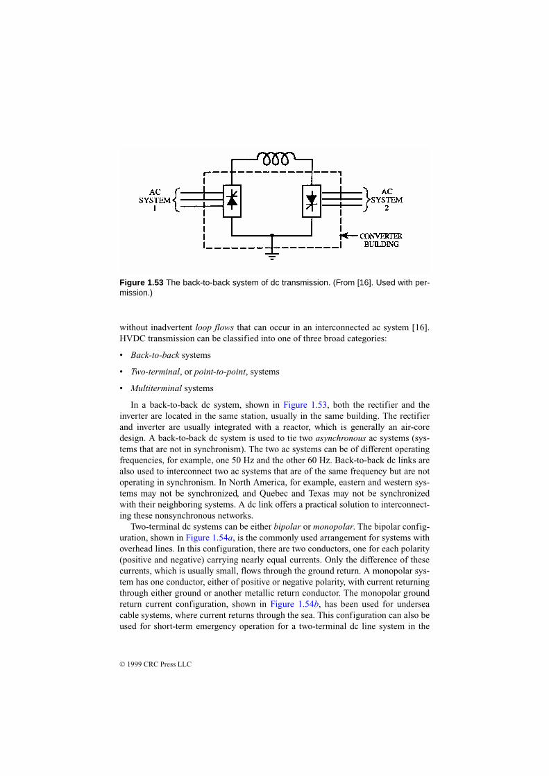
© 1999 CRC Press LLC
without inadvertent loop flows that can occur in an interconnected ac system [16].HVDC transmission can be classified into one of three broad categories:
• Back-to-back systems
• Two-terminal, or point-to-point, systems
• Multiterminal systems
In a back-to-back dc system, shown in Figure 1.53, both the rectifier and theinverter are located in the same station, usually in the same building. The rectifierand inverter are usually integrated with a reactor, which is generally an air-coredesign. A back-to-back dc system is used to tie two asynchronous ac systems (sys-tems that are not in synchronism). The two ac systems can be of different operatingfrequencies, for example, one 50 Hz and the other 60 Hz. Back-to-back dc links arealso used to interconnect two ac systems that are of the same frequency but are notoperating in synchronism. In North America, for example, eastern and western sys-tems may not be synchronized, and Quebec and Texas may not be synchronizedwith their neighboring systems. A dc link offers a practical solution to interconnect-ing these nonsynchronous networks.
Two-terminal dc systems can be either bipolar or monopolar. The bipolar config-uration, shown in Figure 1.54a, is the commonly used arrangement for systems withoverhead lines. In this configuration, there are two conductors, one for each polarity(positive and negative) carrying nearly equal currents. Only the difference of thesecurrents, which is usually small, flows through the ground return. A monopolar sys-tem has one conductor, either of positive or negative polarity, with current returningthrough either ground or another metallic return conductor. The monopolar groundreturn current configuration, shown in Figure 1.54b, has been used for underseacable systems, where current returns through the sea. This configuration can also beused for short-term emergency operation for a two-terminal dc line system in the
Figure 1.53 The back-to-back system of dc transmission. (From [16]. Used with per-mission.)

© 1999 CRC Press LLC
event of a pole outage. However, concerns for corrosion of underground metallicstructures and interference with telephone and other utilities restrict the duration ofsuch operation. The total ampere-hour operation per year is usually the restrictingcriterion. In a monopolar metallic return system, shown in Figure 1.54c, return cur-rent flows through a conductor, thus avoiding the problems associated with groundreturn current. This method is generally used as a contingency mode of operation fora normal bipolar transmission system in the event of a partial converter (one-poleequipment) outage. In the case of outage of a one-pole converter, the conductor ofthe affected pole will be used as the return current conductor. A metallic returntransfer breaker is opened, diverting the return current from the ground path and intothe pole conductor. This conductor is grounded at one end and insulated at the otherend. This system can transmit half the power of the normal bipolar system capacity,and can be increased if overload capacity is available. However, the percentage oflosses will be doubled compared to the normal bipolar operation.
There are two basic configurations in which dc systems can be operated as multi-terminal systems:
• Parallel configuration
• Series configuration
The parallel configuration can be either radial-connected (Figure 1.55a) ormesh-connected (Figure 1.55b). In a parallel-connected multiterminal dc system, allconverters operate at the same nominal dc voltage, similar to ac system interconnec-tions. In this mode of operation, one converter determines the operating voltage, andall other terminals operate in a current-controlling mode.
In a series-connected multiterminal dc system, shown in Figure 1.56, all convert-ers operate at the same current. One converter sets the current that will be commonto all converters in the system. Except for the converter that sets the current, theremaining converters operate in a voltage control mode (constant firing angle orconstant extinction angle). The converters operate almost independently without therequirement for high-speed communication between them. The power output of anoncurrent-controlling converter is varied by changing its voltage. At all times, thesum of the voltages across the rectifier stations must be larger than the sum of volt-ages across the inverter stations. Disadvantages of a series-connected systeminclude the following:
• Reduced efficiency because full line insulation is not used at all times
• Operation at higher firing angles leads to high converter losses and higher reac-tive power requirements from the ac system
1.8.4.1 Economic Comparison of AC and DC Transmission
In cases where HVDC is selected on technical considerations, it may be the onlypractical option, as in the case of an asynchronous interconnection [16]. However,for long-distance power transmission, where both ac and HVDC are practical, the

© 1999 CRC Press LLC
final decision is dependent on the total costs of each alternative. The total cost of atransmission system includes the line costs (conductors, insulators, and towers) plus
(a)
(b)
(c)
Figure 1.54 Two-terminal dc transmission systems: (a) bipolar; (b) monopolarground return; (c) monopolar metallic return. (From [16]. Used with permission.)
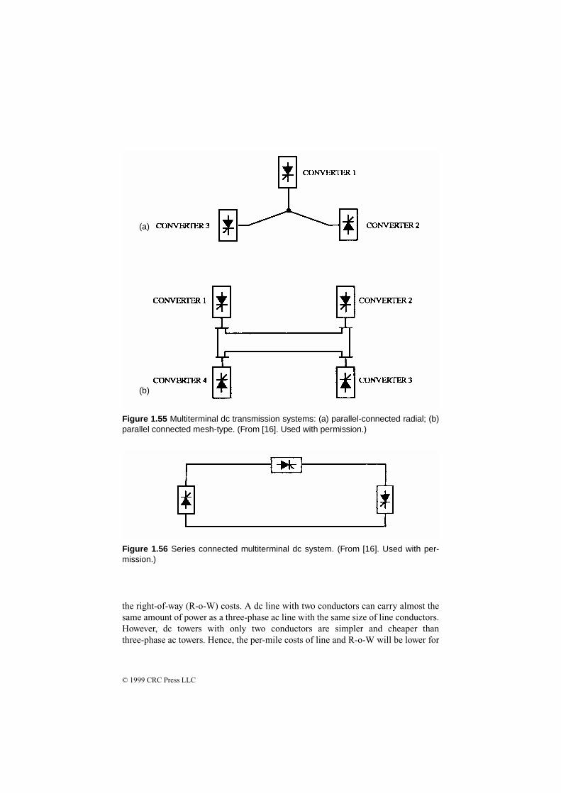
© 1999 CRC Press LLC
the right-of-way (R-o-W) costs. A dc line with two conductors can carry almost thesame amount of power as a three-phase ac line with the same size of line conductors.However, dc towers with only two conductors are simpler and cheaper thanthree-phase ac towers. Hence, the per-mile costs of line and R-o-W will be lower for
(a)
(b)
Figure 1.55 Multiterminal dc transmission systems: (a) parallel-connected radial; (b)parallel connected mesh-type. (From [16]. Used with permission.)
Figure 1.56 Series connected multiterminal dc system. (From [16]. Used with per-mission.)

© 1999 CRC Press LLC
a dc line. Power losses in the dc line are also lower than for ac for the same powertransmitted. However, the HVDC system requires converters at each end of the line;hence, the terminal costs for dc are higher than for ac. The variation of total costs forac and dc as a function of line length is shown in Figure 1.57. As illustrated, there isa break-even distance beyond which the total costs of the dc option will be lowerthan the ac transmission option. This is in the range of 500 to 800 km for overheadlines, but much shorter for cables. The break-even point is between 20 and 50 kmfor submarine cables and twice as far for underground cables.
1.8.4.2 DC Circuit Breakers
The process of interrupting the current in an ac system is aided by the fact that accurrent goes through zero every half-cycle, or approximately every 8 ms in a 60 Hzsystem [16]. The absence of a natural current zero in dc makes it difficult to developa dc circuit breaker. There are three principal problems that must be addressed:
• Forcing current zero in the interrupting element
• Controlling the overvoltages caused by large changes in current as a function oftime (di/dt) in a highly inductive circuit
• Dissipating large amounts of energy (tens of megajoules is not uncommon)
The second and third problems are solved by the application of zinc oxide varistorsconnected line to ground and across the breaking element. The first is the major
Figure 1.57 Transmission system cost as a function of line length for ac and dc sys-tems. (From [16]. Used with permission.)

© 1999 CRC Press LLC
problem, and several different solutions have been adopted by different manufactur-ers. Basically, current zero is achieved by inserting a counter voltage into the circuit.
In the circuit shown in Figure 1.58, opening CB (an air-blast circuit breaker)causes current to be commutated to the parallel LC tank. The commutating circuitwill be oscillatory, which creates current zero in the circuit breaker. The opening ofCB increases the voltage across the commutating circuit, which will be limited bythe zinc oxide varistor ZnO1 by entering into conduction. The resistance R is theclosing resistor in series with switch S.
1.9 Power Factor
Power factor (PF) is an important, but often misunderstood, element of ac powersystem design and operation. It is defined as the ratio of true power to apparentpower, generally expressed as a percentage. (PF also may be expressed as a decimalvalue.) Reactive loads (inductive or capacitive) act on power systems to shift thecurrent out of phase with the voltage. The cosine of the resulting angle between thecurrent and voltage is the power factor.
A utility line that is feeding an inductive load (which is most often the case) issaid to have a lagging power factor, while a line feeding a capacitive load has aleading power factor. See Figure 1.59. A poor power factor will result in excessivelosses along utility company feeder lines because more current is required to supplya given load with a low power factor than the same load with a power factor close tounity.
Figure 1.58 Block diagram of a dc circuit breaker (one module). (From [16]. Usedwith permission.)
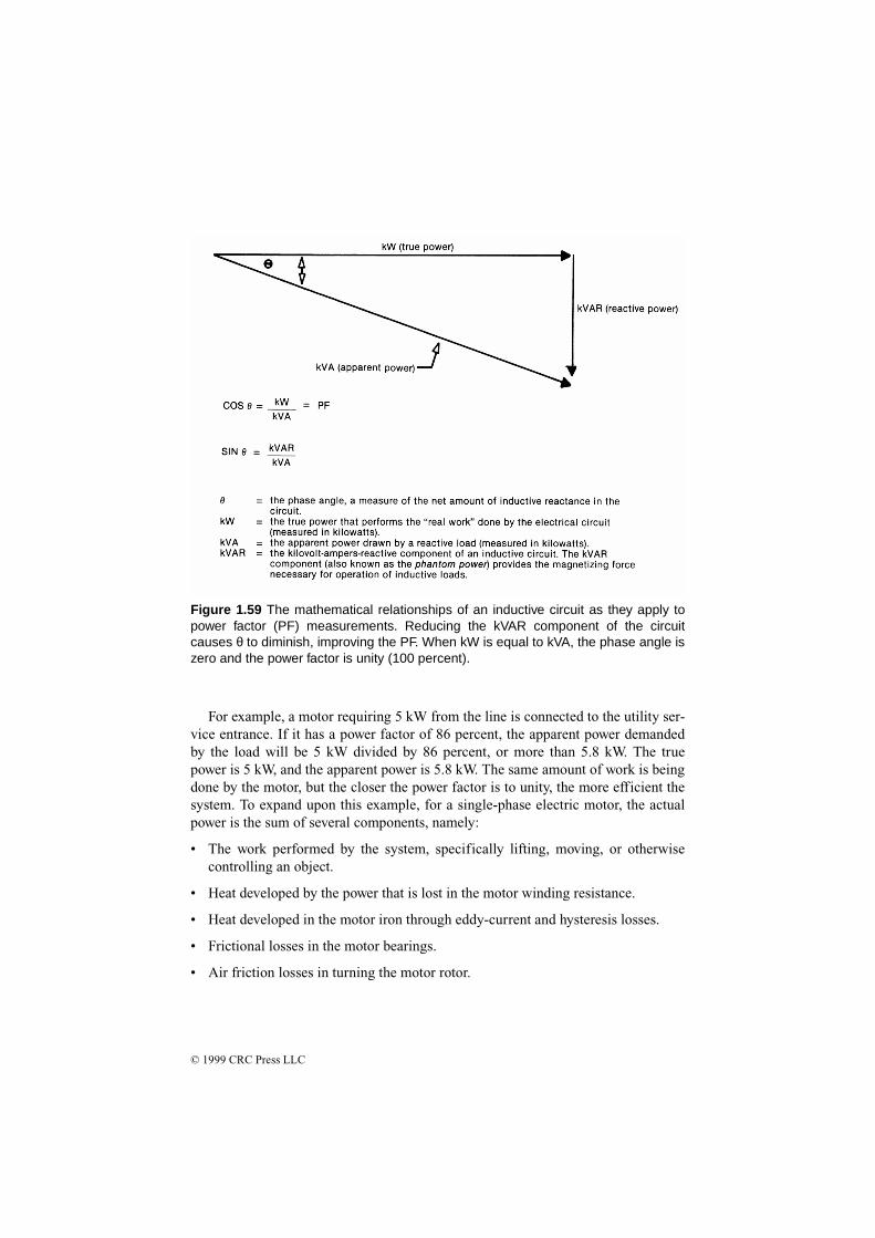
© 1999 CRC Press LLC
For example, a motor requiring 5 kW from the line is connected to the utility ser-vice entrance. If it has a power factor of 86 percent, the apparent power demandedby the load will be 5 kW divided by 86 percent, or more than 5.8 kW. The truepower is 5 kW, and the apparent power is 5.8 kW. The same amount of work is beingdone by the motor, but the closer the power factor is to unity, the more efficient thesystem. To expand upon this example, for a single-phase electric motor, the actualpower is the sum of several components, namely:
• The work performed by the system, specifically lifting, moving, or otherwisecontrolling an object.
• Heat developed by the power that is lost in the motor winding resistance.
• Heat developed in the motor iron through eddy-current and hysteresis losses.
• Frictional losses in the motor bearings.
• Air friction losses in turning the motor rotor.
Figure 1.59 The mathematical relationships of an inductive circuit as they apply topower factor (PF) measurements. Reducing the kVAR component of the circuitcauses θ to diminish, improving the PF. When kW is equal to kVA, the phase angle iszero and the power factor is unity (100 percent).

© 1999 CRC Press LLC
All these values are expressed in watts or kilowatts, and can be measured with awattmeter. They represent the actual power. The apparent power is determined bymeasuring the current and voltage with an ammeter and a voltmeter, then calculatingthe product of the two. In the single-phase motor example, the apparent power thusobtained is greater than the actual power. The reason for this is the power factor.
The PF reflects the differences that exist between different types of loads. A sol-dering iron is a purely resistive load that converts current directly into heat. The cur-rent is called actual current because it contributes directly to the production of actualpower. On the other hand, the single-phase electric motor represents a partiallyinductive load. The motor current consists of actual current that is converted intoactual power, and a magnetizing current that is used to generate the magnetic fieldrequired for operation of the device. This magnetizing current corresponds to anexchange of energy between the power source and the motor, but it is not convertedinto actual power. This current is identified as the reactive current in the circuit.
As illustrated in Figure 1.60, in a resistive circuit, the current is in phase with thevoltage. In a purely inductive circuit, the current lags the voltage by 90°. This rela-tionship can be represented graphically by vectors, as shown in the figure. For a cir-cuit with both inductive and resistive components, as in the motor example, the twoconditions exist simultaneously. The distribution between the actual power and thereactive power is illustrated in Figure 1.61. The power factor, which has beendefined previously as the ratio between actual power and apparent power, is also thecosine of the angle θ. The greater the angle θ becomes, the lower the power factor.
Determining the power factor for a given element of a power-distribution systemis complicated by the variety of loads typically connected. Different loads presentdifferent PF components:
• Lighting. The PF for most incandescent lamps is unity. Fluorescent lamps usuallyhave a low power factor; 50 percent is typical. Fluorescent lamps sometimes aresupplied with compensation devices to correct for low power factor. Mercuryvapor lamps have a low PF; 40 to 60 percent is typical. Again, such devices canbe supplied with compensation devices.
• Electric motors. The PP of an induction motor varies with the load, as shown inFigure 1.62. Unloaded or lightly loaded motors exhibit a low PF. Figure 1.63illustrates the variation of PF and reactive power for varying loads on a three-phase induction motor. Synchronous motors provide good PF when their excita-tion is adjusted properly. Synchronous motors also can be over-excited to exhibita leading power factor and, therefore, can be used to improve the power factor ofa facility.
• Heating systems. Most heating systems used in ovens or dryers present a PF ofclose to unity.
• Welding equipment. Electric arc welders usually have a low PF; 60 percent istypical.
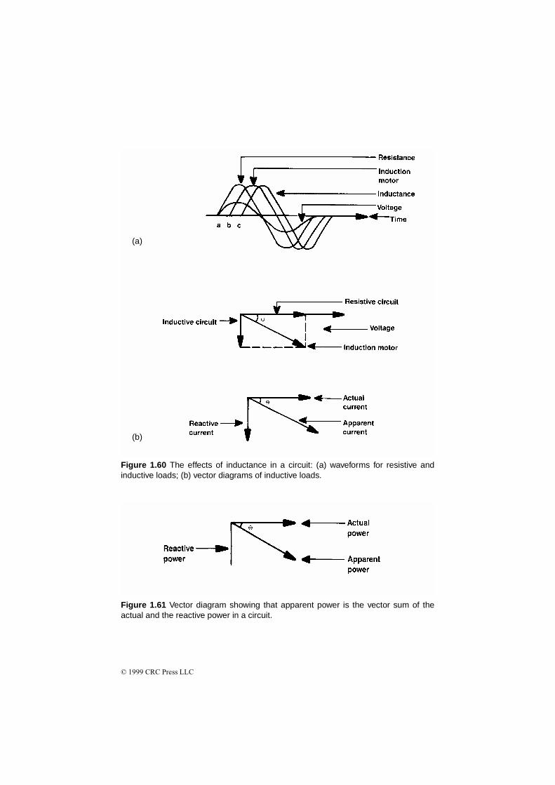
© 1999 CRC Press LLC
(a)
(b)
Figure 1.60 The effects of inductance in a circuit: (a) waveforms for resistive andinductive loads; (b) vector diagrams of inductive loads.
Figure 1.61 Vector diagram showing that apparent power is the vector sum of theactual and the reactive power in a circuit.
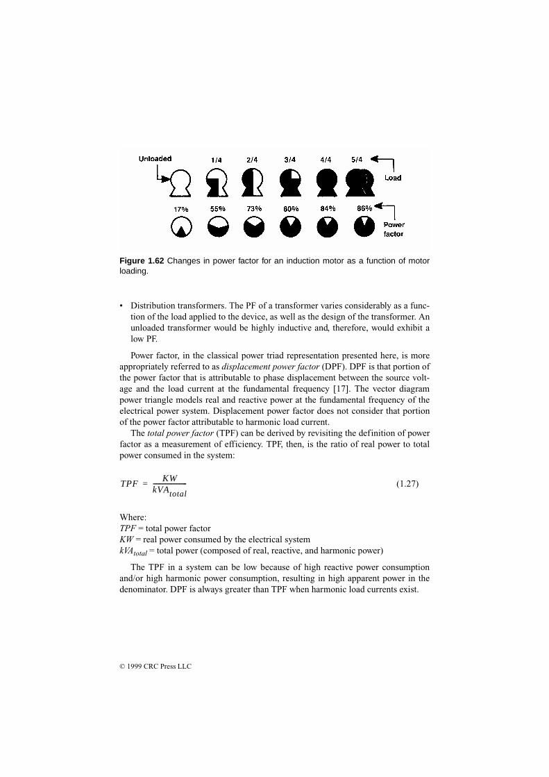
© 1999 CRC Press LLC
• Distribution transformers. The PF of a transformer varies considerably as a func-tion of the load applied to the device, as well as the design of the transformer. Anunloaded transformer would be highly inductive and, therefore, would exhibit alow PF.
Power factor, in the classical power triad representation presented here, is moreappropriately referred to as displacement power factor (DPF). DPF is that portion ofthe power factor that is attributable to phase displacement between the source volt-age and the load current at the fundamental frequency [17]. The vector diagrampower triangle models real and reactive power at the fundamental frequency of theelectrical power system. Displacement power factor does not consider that portionof the power factor attributable to harmonic load current.
The total power factor (TPF) can be derived by revisiting the definition of powerfactor as a measurement of efficiency. TPF, then, is the ratio of real power to totalpower consumed in the system:
(1.27)
Where:TPF = total power factorKW = real power consumed by the electrical systemkVAtotal = total power (composed of real, reactive, and harmonic power)
The TPF in a system can be low because of high reactive power consumptionand/or high harmonic power consumption, resulting in high apparent power in thedenominator. DPF is always greater than TPF when harmonic load currents exist.
TPFKW
kVAtotal----------------------=
Figure 1.62 Changes in power factor for an induction motor as a function of motorloading.
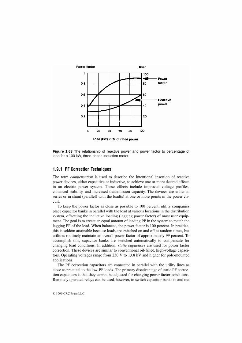
© 1999 CRC Press LLC
1.9.1 PF Correction Techniques
The term compensation is used to describe the intentional insertion of reactivepower devices, either capacitive or inductive, to achieve one or more desired effectsin an electric power system. These effects include improved voltage profiles,enhanced stability, and increased transmission capacity. The devices are either inseries or in shunt (parallel) with the load(s) at one or more points in the power cir-cuit.
To keep the power factor as close as possible to 100 percent, utility companiesplace capacitor banks in parallel with the load at various locations in the distributionsystem, offsetting the inductive loading (lagging power factor) of most user equip-ment. The goal is to create an equal amount of leading PP in the system to match thelagging PF of the load. When balanced, the power factor is 100 percent. In practice,this is seldom attainable because loads are switched on and off at random times, bututilities routinely maintain an overall power factor of approximately 99 percent. Toaccomplish this, capacitor banks are switched automatically to compensate forchanging load conditions. In addition, static capacitors are used for power factorcorrection. These devices are similar to conventional oil-filled, high-voltage capaci-tors. Operating voltages range from 230 V to 13.8 kV and higher for pole-mountedapplications.
The PF correction capacitors are connected in parallel with the utility lines asclose as practical to the low-PF loads. The primary disadvantage of static PF correc-tion capacitors is that they cannot be adjusted for changing power factor conditions.Remotely operated relays can be used, however, to switch capacitor banks in and out
Figure 1.63 The relationship of reactive power and power factor to percentage ofload for a 100 kW, three-phase induction motor.

© 1999 CRC Press LLC
of the circuit as required. Synchronous capacitors, on the other hand, can be adjustedto provide varying capacitance to correct for varying PF loads. The capacitive effectof a synchronous capacitor is changed by varying the dc excitation voltage appliedto the rotor of the device.
Utilities usually pass on to customers the costs of operating low-PF loads. Powerfactor can be billed as one, or a combination, of the following:
• A penalty for PF below a predetermined value or a credit for PF above a prede-termined value.
• An increasing penalty for decreasing PF.
• A charge on monthly kVAR hours.
• A straight charge for the maximum value of kVA used during the month.
Aside from direct costs from utility companies for low-PF operation, the end-userexperiences a number of indirect costs as well. When a facility operates with a lowoverall PF, the amount of useful electrical energy available inside the plant at thedistribution transformer is reduced considerably because of the amount of reactiveenergy that the transformer(s) must carry. Figure 1.64 illustrates the reduction inavailable power from a distribution transformer when presented with varying PFloads. Figure 1.65 illustrates the increase in I2R losses in feeder and branch circuitswith varying PF loads. These conditions result in the need for oversized cables,transformers, switchgear, and protection circuits.
The copper losses in a system are proportional to the square of the load current.The installation of PF correction capacitors near offending low PF loads decreases
Figure 1.64 The effects of power factor on the output of a transformer.
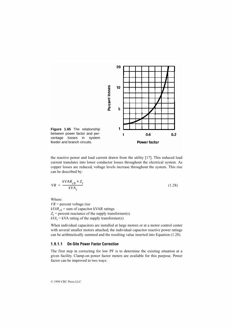
© 1999 CRC Press LLC
the reactive power and load current drawn from the utility [17]. This reduced loadcurrent translates into lower conductor losses throughout the electrical system. Ascopper losses are reduced, voltage levels increase throughout the system. This risecan be described by:
(1.28)
Where:VR = percent voltage risekVARcb = sum of capacitor kVAR ratingsZt = percent reactance of the supply transformer(s)kVAt = kVA rating of the supply transformer(s)
When individual capacitors are installed at large motors or at a motor control centerwith several smaller motors attached, the individual capacitor reactive power ratingscan be arithmetically summed and the resulting value inserted into Equation (1.28).
1.9.1.1 On-Site Power Factor Correction
The first step in correcting for low PF is to determine the existing situation at agiven facility. Clamp-on power factor meters are available for this purpose. Powerfactor can be improved in two ways:
VRkVARcb Zt×
kVAt-------------------------------=
Figure 1.65 The relationshipbetween power factor and per-centage losses in systemfeeder and branch circuits.

© 1999 CRC Press LLC
• Reduce the amount of reactive energy by eliminating low PF loads, such asunloaded motors and transformers.
• Apply external compensation capacitors or other devices to correct the low-PFcondition.
PF correction capacitors perform the function of an energy-storage device. Insteadof transferring reactive energy back and forth between the load and the powersource, the magnetizing current reactive energy is stored in a capacitor at the load.Capacitors are rated in kVARs, and are available for single- and multiphase loads.Usually, more than one capacitor is required to yield the desired degree of PF cor-rection. The capacitor rating required in a given application can be determined byusing lookup tables provided by PF capacitor manufacturers. Installation optionsinclude:
• Individual capacitors placed at each machine
• A group or bank installation for an entire area of the plant
• A combination of the two approaches
Figure 1.66a shows a simple circuit with shunt capacitor compensation applied atthe load. The line current IL is the sum of the motor load current IM and the capacitorcurrent IC. From the current phasor diagram of Figure 1.66b, it can be seen that theline current is reduced with the insertion of the shunt capacitor. Figure 1.66c dis-plays the corresponding voltage phasors. The effect of the shunt capacitor is toincrease the voltage source to VS1 from VS0.
When rectifier loads that generate harmonic load current are the cause of a low-PF condition, the addition of PF correcting capacitors will not necessarily providethe desired improvement. The capacitors, in some cases, may actually raise the linecurrent and fail to improve the power factor. Harmonic currents generally are mostapparent in the neutral of three-phase circuits. Conductors supplying three-phaserectifiers using a neutral conductor require a neutral conductor that is as large as thephase conductors. A reduced neutral should not be permitted. When adding capaci-tors for PF correction, be careful to avoid any unwanted voltage resonances thatmight be excited by harmonic load currents.
If a delta/wye connected power transformer is installed between the power sourceand the load, the power factor at the transformer input generally will reflect the aver-age PF of the load on the secondary. This conclusion works on the assumption thatthe low PF is caused by inductive and capacitive reactances in the loads. However, ifthe load current is rich in harmonics from rectifiers and switching regulators, someof the harmonic currents will flow no farther toward the power source than the trans-former delta winding. The third harmonic and multiples of three will flow in thedelta winding and will be significantly reduced in amplitude. By this means, thetransformer will provide some improvement in the PF of the total load.
An economic evaluation of the cost vs. benefits, plus a review of any mandatoryutility company limits that must be observed for PF correction, will determine how

© 1999 CRC Press LLC
much power factor correction, if any, may be advisable at a given facility. Figure1.67 shows a “before” and “after” comparison of a hypothetical facility. Correctionto 85 percent will satisfy many requirements. No economic advantage is likely toresult from correcting to 95 percent or greater. Overcorrecting a load by placing toomany PF correction capacitors can reduce the power factor after reaching unity, andcause uncontrollable overvoltages in low-kVA-capacity power sources.
PF correcting capacitors usually offer some benefits in absorbing line-voltageimpulse-type noise spikes. However, if the capacitors are switched on and off, theywill create significant impulses of their own. Switching can be accomplished withacceptably low disturbance using soft-start or preinsertion resistors. Such resistorsare connected momentarily in series with the capacitors. After a brief delay (0.5 s orless), the resistors are short-circuited, connecting the capacitors directly across theline.
Installation of PF correction capacitors at a facility is a complicated process thatrequires a knowledgeable consultant and licensed electrician. The local utility com-pany should be contacted before any effort is made to improve the PF of a facility.
(a)
(c)(b)
Figure 1.66 Shunt-capacitor compensation: (a) schematic diagram; (b) current pha-sor diagram; (c) voltage phasor diagram. (From [17]. Used with permission.)
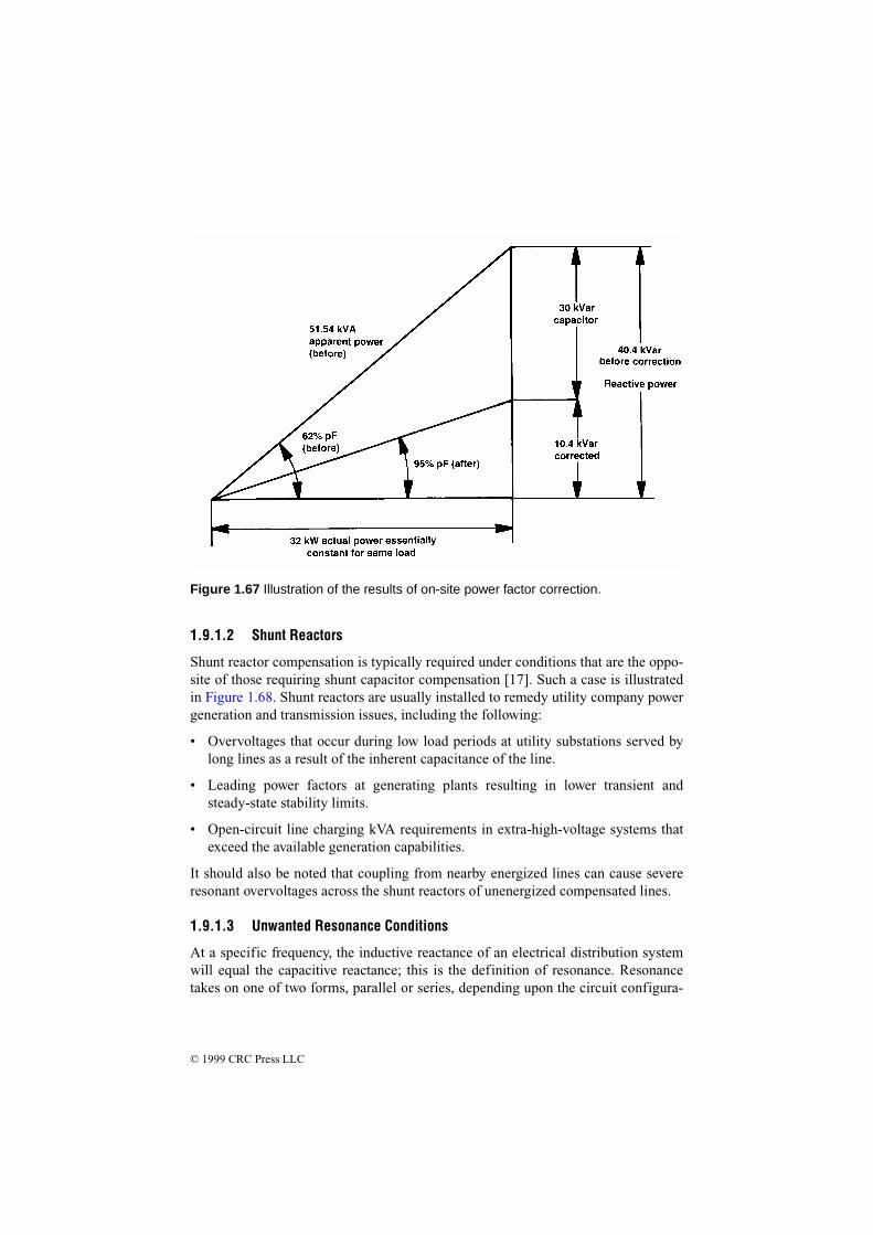
© 1999 CRC Press LLC
1.9.1.2 Shunt Reactors
Shunt reactor compensation is typically required under conditions that are the oppo-site of those requiring shunt capacitor compensation [17]. Such a case is illustratedin Figure 1.68. Shunt reactors are usually installed to remedy utility company powergeneration and transmission issues, including the following:
• Overvoltages that occur during low load periods at utility substations served bylong lines as a result of the inherent capacitance of the line.
• Leading power factors at generating plants resulting in lower transient andsteady-state stability limits.
• Open-circuit line charging kVA requirements in extra-high-voltage systems thatexceed the available generation capabilities.
It should also be noted that coupling from nearby energized lines can cause severeresonant overvoltages across the shunt reactors of unenergized compensated lines.
1.9.1.3 Unwanted Resonance Conditions
At a specific frequency, the inductive reactance of an electrical distribution systemwill equal the capacitive reactance; this is the definition of resonance. Resonancetakes on one of two forms, parallel or series, depending upon the circuit configura-
Figure 1.67 Illustration of the results of on-site power factor correction.
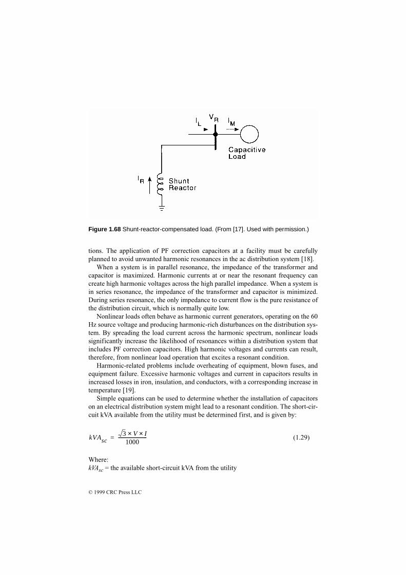
© 1999 CRC Press LLC
tions. The application of PF correction capacitors at a facility must be carefullyplanned to avoid unwanted harmonic resonances in the ac distribution system [18].
When a system is in parallel resonance, the impedance of the transformer andcapacitor is maximized. Harmonic currents at or near the resonant frequency cancreate high harmonic voltages across the high parallel impedance. When a system isin series resonance, the impedance of the transformer and capacitor is minimized.During series resonance, the only impedance to current flow is the pure resistance ofthe distribution circuit, which is normally quite low.
Nonlinear loads often behave as harmonic current generators, operating on the 60Hz source voltage and producing harmonic-rich disturbances on the distribution sys-tem. By spreading the load current across the harmonic spectrum, nonlinear loadssignificantly increase the likelihood of resonances within a distribution system thatincludes PF correction capacitors. High harmonic voltages and currents can result,therefore, from nonlinear load operation that excites a resonant condition.
Harmonic-related problems include overheating of equipment, blown fuses, andequipment failure. Excessive harmonic voltages and current in capacitors results inincreased losses in iron, insulation, and conductors, with a corresponding increase intemperature [19].
Simple equations can be used to determine whether the installation of capacitorson an electrical distribution system might lead to a resonant condition. The short-cir-cuit kVA available from the utility must be determined first, and is given by:
(1.29)
Where:kVAsc = the available short-circuit kVA from the utility
kVAsc3 V I××1000
-------------------------=
Figure 1.68 Shunt-reactor-compensated load. (From [17]. Used with permission.)
© 1999 CRC Press LLC
V = system operating voltageI = available short-circuit current
Next, the building or facility distribution system short circuit capacity must be cal-culated, as given by:
(1.30)
Where:kVAsys = the short circuit capacity of the secondary electrical systemkVAt = kVA rating of the substation transformer(s)kVAsc = available short-circuit kVA from the utilityzt = impedance of the substation transformer(s)
The resonant harmonic of the distribution system under analysis is given by:
(1.31)
Where:hr = the resonant harmonickVAsys = available short-circuit kVA from the distribution systemkVAmc = available short-circuit kVA from motor contributionkVARc = sum of capacitor kVAR ratings
A resonant harmonic on the order of 50 or greater does not usually represent apotential resonant condition; because the distribution system inductive reactanceincreases proportionally with frequency, higher order harmonic currents are signifi-cantly attenuated. Additionally, harmonic analysis may reveal negligible harmoniccurrent magnitudes at or near the resonant frequency. In either case, harmonic miti-gation techniques may not be required to prevent resonance within the distributionsystem.
When Equation (1.31) indicates a relatively low resonant harmonic, and spec-trum analyses indicate that the magnitude of harmonic currents are significant at ornear the resonant frequency, the most likely solution will be to install harmonic fil-ters. In fact, low total power factor can be principally the result of harmonic currentsgenerated by the load. In such instances, the TPF may be improved by installing fil-ters or traps alone [20]. In most cases, a combination of harmonic filters and capaci-tors designed to operate at the fundamental frequency are required to improve theTPF to acceptable levels in systems in which harmonic currents are present.
kVAsys
kVAt kVAsc×kVAt Zt kVAsc×( )+--------------------------------------------------=
hr
kVAsys kVAmc+
kVARc------------------------------------------=
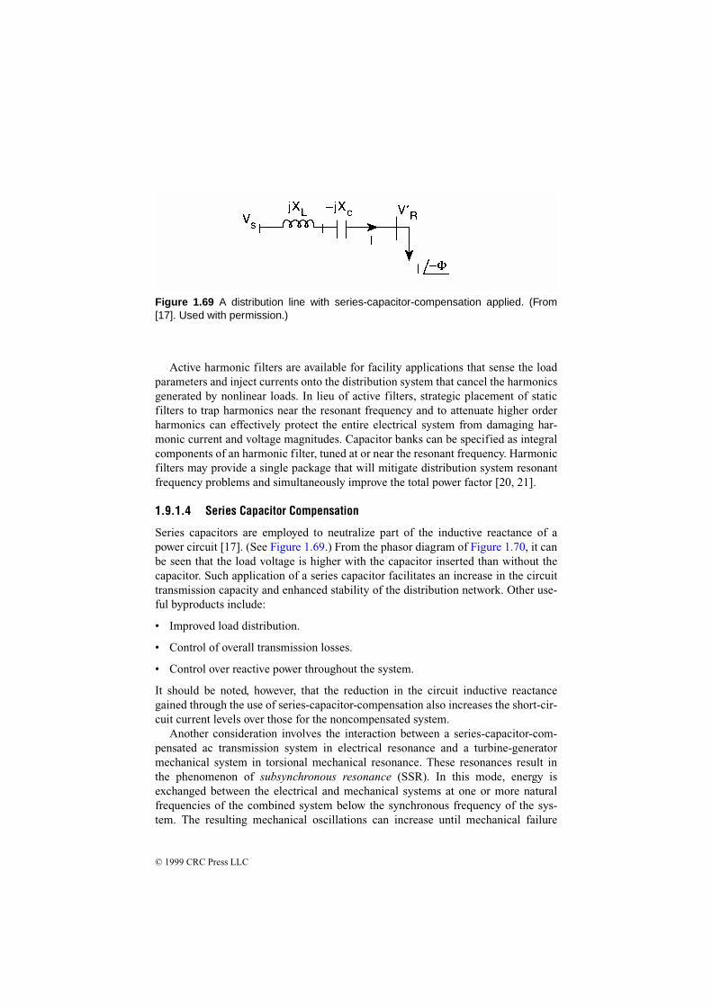
© 1999 CRC Press LLC
Active harmonic filters are available for facility applications that sense the loadparameters and inject currents onto the distribution system that cancel the harmonicsgenerated by nonlinear loads. In lieu of active filters, strategic placement of staticfilters to trap harmonics near the resonant frequency and to attenuate higher orderharmonics can effectively protect the entire electrical system from damaging har-monic current and voltage magnitudes. Capacitor banks can be specified as integralcomponents of an harmonic filter, tuned at or near the resonant frequency. Harmonicfilters may provide a single package that will mitigate distribution system resonantfrequency problems and simultaneously improve the total power factor [20, 21].
1.9.1.4 Series Capacitor Compensation
Series capacitors are employed to neutralize part of the inductive reactance of apower circuit [17]. (See Figure 1.69.) From the phasor diagram of Figure 1.70, it canbe seen that the load voltage is higher with the capacitor inserted than without thecapacitor. Such application of a series capacitor facilitates an increase in the circuittransmission capacity and enhanced stability of the distribution network. Other use-ful byproducts include:
• Improved load distribution.
• Control of overall transmission losses.
• Control over reactive power throughout the system.
It should be noted, however, that the reduction in the circuit inductive reactancegained through the use of series-capacitor-compensation also increases the short-cir-cuit current levels over those for the noncompensated system.
Another consideration involves the interaction between a series-capacitor-com-pensated ac transmission system in electrical resonance and a turbine-generatormechanical system in torsional mechanical resonance. These resonances result inthe phenomenon of subsynchronous resonance (SSR). In this mode, energy isexchanged between the electrical and mechanical systems at one or more naturalfrequencies of the combined system below the synchronous frequency of the sys-tem. The resulting mechanical oscillations can increase until mechanical failure
Figure 1.69 A distribution line with series-capacitor-compensation applied. (From[17]. Used with permission.)

© 1999 CRC Press LLC
occurs. A number of measures can be taken to reduce or eliminate SSR, as describedin [17].
1.9.1.5 Static Compensation Devices
Advances in thyristor technology for power system applications have led to thedevelopment of the static VAR compensator (SVC) [17]. This class of devices con-tains standard shunt elements (reactors and capacitors) that are controlled by thyris-tors. Static VAR devices are used to address two common problems encountered inpractical power systems:
• Load compensation, where there is a need to reduce or cancel the reactive powerdemand of large and fluctuating industrial loads. Because heavy industrial loadsare normally concentrated in one plant and served from one network terminal,they can usually be handled by a local compensator connected to the same termi-nal.
• Balancing the real power drawn from the ac supply lines. This type of compensa-tion is related to the voltage support of transmission lines at a given terminal inresponse to disturbances of both the load and the supply. This voltage support isachieved by rapid control of the SVC reactance and, thus, its reactive power out-put.
The main objectives of such VAR compensation schemes are:
• To increase the stability limit of the ac power system.
• Decrease terminal voltage fluctuations during load changes.
• Limit overvoltages resulting from large system disturbances.
Figure 1.70 Phasor diagram corresponding to the circuit shown in Figure 1.69. (From[17]. Used with permission.)

© 1999 CRC Press LLC
SVCs are essentially thyristor-controlled reactive power devices, usually designedaround one of two basic configurations:
• Thyristor-switched shunt capacitor (TSC). As illustrated in Figure 1.71a, thisconfiguration splits a capacitor bank into small steps and switches those steps onand off individually. This approach offers stepwise control, virtually no tran-sients, and no harmonic generation. The average delay for executing a commandfrom the regulator is one-half a cycle.
• Thyristor-switched shunt reactor (TSR). Shown in Figure 1.71b, the fundamentalfrequency current component through the reactor is controlled by delaying theclosing of the thyristor switch with respect to the natural zero crossing of the cur-rent. In this case, harmonic currents are generated from the phase-angle-con-trolled device.
In many applications, the arrangement of the SVC consists of a few large steps ofthyristor-switched capacitors and one or two thyristor-controlled reactors, as shownin figure 1.71c.
Figure 1.71 Basic static VAR compensator configurations: (a) thyristor-switchedshunt capacitors (TSC); (b) thyristor-switched shunt reactors (TSR); (c) combinedTSC/TSR. (From [17]. Used with permission.)
(b) (c)(a)
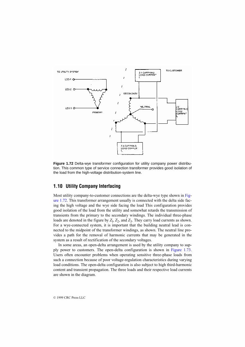
© 1999 CRC Press LLC
1.10 Utility Company Interfacing
Most utility company-to-customer connections are the delta-wye type shown in Fig-ure 1.72. This transformer arrangement usually is connected with the delta side fac-ing the high voltage and the wye side facing the load This configuration providesgood isolation of the load from the utility and somewhat retards the transmission oftransients from the primary to the secondary windings. The individual three-phaseloads are denoted in the figure by Zl, Z2, and Z3. They carry load currents as shown.For a wye-connected system, it is important that the building neutral lead is con-nected to the midpoint of the transformer windings, as shown. The neutral line pro-vides a path for the removal of harmonic currents that may be generated in thesystem as a result of rectification of the secondary voltages.
In some areas, an open-delta arrangement is used by the utility company to sup-ply power to customers. The open-delta configuration is shown in Figure 1.73.Users often encounter problems when operating sensitive three-phase loads fromsuch a connection because of poor voltage-regulation characteristics during varyingload conditions. The open-delta configuration is also subject to high third-harmoniccontent and transient propagation. The three loads and their respective load currentsare shown in the diagram.
Figure 1.72 Delta-wye transformer configuration for utility company power distribu-tion. This common type of service connection transformer provides good isolation ofthe load from the high-voltage distribution-system line.

© 1999 CRC Press LLC
Other primary power connection arrangements are possible, such as wye-to-wyeor delta-to-delta. Like the delta-to-wye configuration, they are not susceptible to theproblems that may be experienced with the open-delta (or V-V) service.
The open-delta system can develop a considerable imbalance among the individ-ual phases in either voltage or phase or both. This can introduce a strong 120 Hz rip-ple frequency in three-phase power supplies, which are designed to filter out a 360Hz ripple. The effects of this 120 Hz ripple can be increased noise in the supply andpossible damage to protection devices across the power-supply chokes. Dependingon the loading of an open-delta transformer, high third-harmonic energy can betransferred to the load, producing transients of up to 300 percent of the normal volt-age. The result could be severely strained rectifiers, capacitors, and inductors in thepower supply as well as additional output noise of the supply.
1.10.1 Phase-to-Phase Balance
The phase-to-phase voltage balance of a utility company line is important at mosttypes of facilities, not only because of the increased power-supply ripple that it cancause, but also because of the possible heating effects. Even simple three-phase
Figure 1.73 The open-delta (or V-V) utility company service connection transformer.This configuration is not recommended because of its poor voltage regulation undervarying load, high third-harmonic content, and transient disturbance propagationcharacteristics.
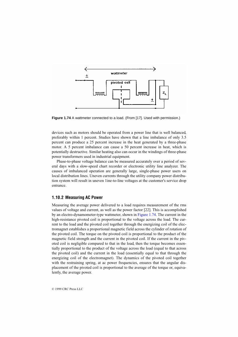
© 1999 CRC Press LLC
devices such as motors should be operated from a power line that is well balanced,preferably within 1 percent. Studies have shown that a line imbalance of only 3.5percent can produce a 25 percent increase in the heat generated by a three-phasemotor. A 5 percent imbalance can cause a 50 percent increase in heat, which ispotentially destructive. Similar heating also can occur in the windings of three-phasepower transformers used in industrial equipment.
Phase-to-phase voltage balance can be measured accurately over a period of sev-eral days with a slow-speed chart recorder or electronic utility line analyzer. Thecauses of imbalanced operation are generally large, single-phase power users onlocal distribution lines. Uneven currents through the utility company power distribu-tion system will result in uneven 1ine-to-line voltages at the customer's service dropentrance.
1.10.2 Measuring AC Power
Measuring the average power delivered to a load requires measurement of the rmsvalues of voltage and current, as well as the power factor [22]. This is accomplishedby an electro-dynamometer-type wattmeter, shown in Figure 1.74. The current in thehigh-resistance pivoted coil is proportional to the voltage across the load. The cur-rent to the load and the pivoted coil together through the energizing coil of the elec-tromagnet establishes a proportional magnetic field across the cylinder of rotation ofthe pivoted coil. The torque on the pivoted coil is proportional to the product of themagnetic field strength and the current in the pivoted coil. If the current in the piv-oted coil is negligible compared to that in the load, then the torque becomes essen-tially proportional to the product of the voltage across the load (equal to that acrossthe pivoted coil) and the current in the load (essentially equal to that through theenergizing coil of the electromagnet). The dynamics of the pivoted coil togetherwith the restraining spring, at ac power frequencies, ensures that the angular dis-placement of the pivoted coil is proportional to the average of the torque or, equiva-lently, the average power.
Figure 1.74 A wattmeter connected to a load. (From [17]. Used with permission.)
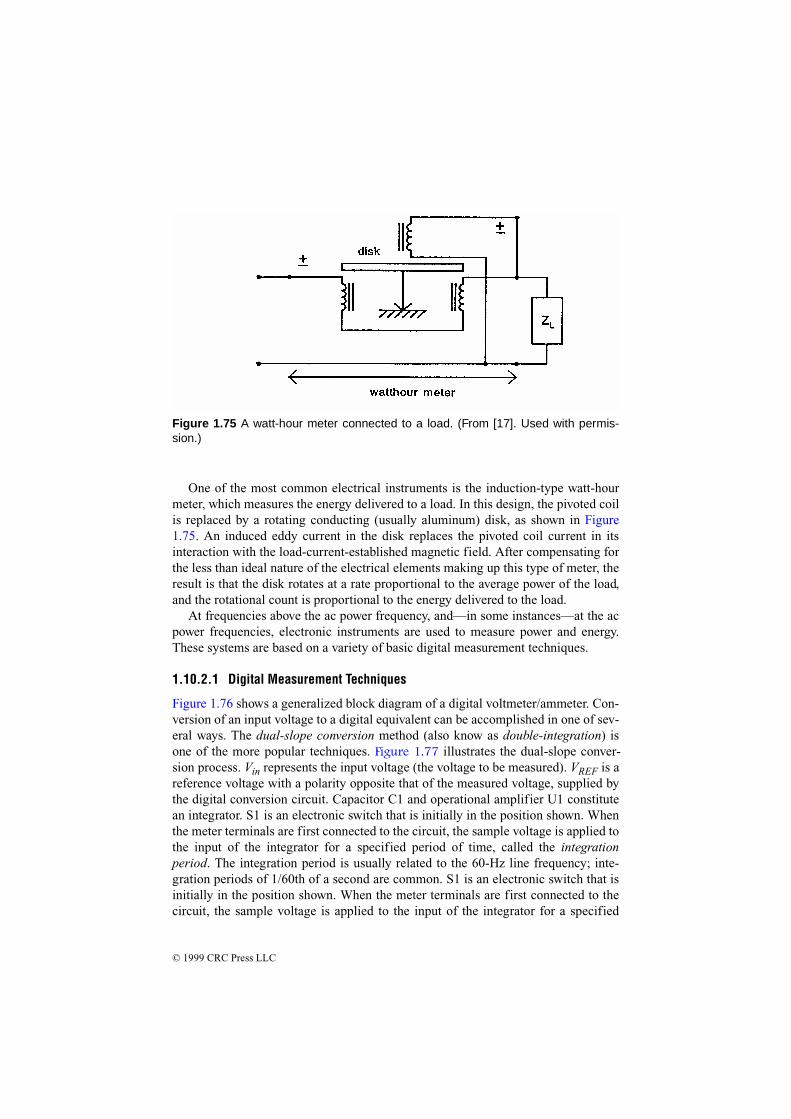
© 1999 CRC Press LLC
One of the most common electrical instruments is the induction-type watt-hourmeter, which measures the energy delivered to a load. In this design, the pivoted coilis replaced by a rotating conducting (usually aluminum) disk, as shown in Figure1.75. An induced eddy current in the disk replaces the pivoted coil current in itsinteraction with the load-current-established magnetic field. After compensating forthe less than ideal nature of the electrical elements making up this type of meter, theresult is that the disk rotates at a rate proportional to the average power of the load,and the rotational count is proportional to the energy delivered to the load.
At frequencies above the ac power frequency, and—in some instances—at the acpower frequencies, electronic instruments are used to measure power and energy.These systems are based on a variety of basic digital measurement techniques.
1.10.2.1 Digital Measurement Techniques
Figure 1.76 shows a generalized block diagram of a digital voltmeter/ammeter. Con-version of an input voltage to a digital equivalent can be accomplished in one of sev-eral ways. The dual-slope conversion method (also know as double-integration) isone of the more popular techniques. Figure 1.77 illustrates the dual-slope conver-sion process. Vin represents the input voltage (the voltage to be measured). VREF is areference voltage with a polarity opposite that of the measured voltage, supplied bythe digital conversion circuit. Capacitor C1 and operational amplifier U1 constitutean integrator. S1 is an electronic switch that is initially in the position shown. Whenthe meter terminals are first connected to the circuit, the sample voltage is applied tothe input of the integrator for a specified period of time, called the integrationperiod. The integration period is usually related to the 60-Hz line frequency; inte-gration periods of 1/60th of a second are common. S1 is an electronic switch that isinitially in the position shown. When the meter terminals are first connected to thecircuit, the sample voltage is applied to the input of the integrator for a specified
Figure 1.75 A watt-hour meter connected to a load. (From [17]. Used with permis-sion.)

© 1999 C
RC
Press L
LC
Figure 1.76 Block diagram of a basic digital voltage and current measuring device. It should be noted that advances in integrated circuittechnology have reduced most of the individual elements shown to single device.
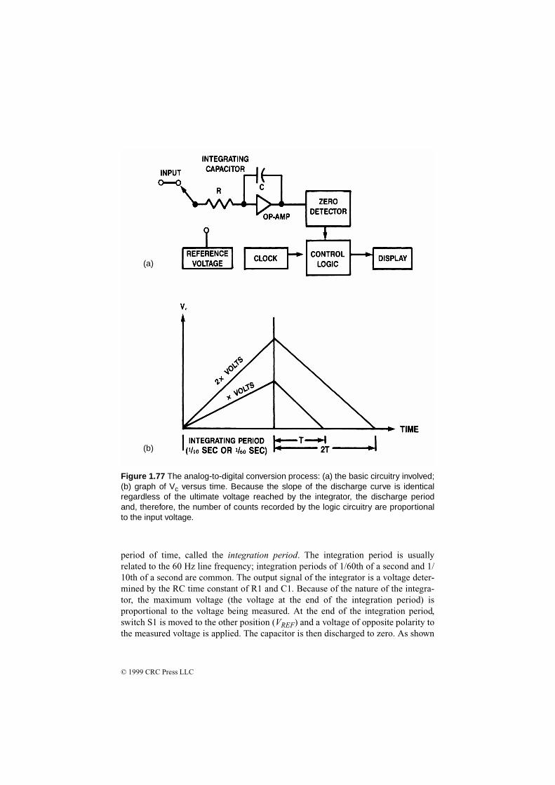
© 1999 CRC Press LLC
period of time, called the integration period. The integration period is usuallyrelated to the 60 Hz line frequency; integration periods of 1/60th of a second and 1/10th of a second are common. The output signal of the integrator is a voltage deter-mined by the RC time constant of R1 and C1. Because of the nature of the integra-tor, the maximum voltage (the voltage at the end of the integration period) isproportional to the voltage being measured. At the end of the integration period,switch S1 is moved to the other position (VREF) and a voltage of opposite polarity tothe measured voltage is applied. The capacitor is then discharged to zero. As shown
(a)
(b)
Figure 1.77 The analog-to-digital conversion process: (a) the basic circuitry involved;(b) graph of Vc versus time. Because the slope of the discharge curve is identicalregardless of the ultimate voltage reached by the integrator, the discharge periodand, therefore, the number of counts recorded by the logic circuitry are proportionalto the input voltage.

© 1999 CRC Press LLC
in the figure, the discharge interval is directly proportional to the maximum voltage,which, in turn, is proportional to the applied voltage at the input terminals.
At the same time that the integration interval ends and the discharge intervalbegins, a counter in the meter begins counting pulses generated by a clock circuit.When the voltage reaches zero, the counter stops. The number of pulses counted is,therefore, proportional to the discharge period. This count is converted to a digitalnumber and displayed as the measured quantity. Although this method works well, itis somewhat slow, so many microcomputer-based meters use a variation called mul-tislope integration.
1.11 References
1. Bose, Bimal K., “Recent Advances in Power Electronics,” IEEE Transactionson Power Electronics, IEEE, New York, Vol. 7, No. 1, pp. 2, January 1992.
2. Bose, Bimal K., “Power Electronics—A Technology Review,” Proceedings ofthe IEEE, IEEE, New York, Vol. 80, No. 8, pp. 1303, August 1992.
3. Chowdhury, Badrul, “Power Distribution and Control,” in The ElectronicsHandbook, Jerry C. Whitaker (ed.), pp. 1003, CRC Press, Boca Raton, FL,1996.
4. Ula, Sadrul, “Transformers,” in The Electronics Handbook, Jerry C. Whitaker(ed.), pp. 927, CRC Press, Boca Raton, FL, 1996.
5. Sankaran, C., “Transformers,” in The Electrical Engineering Handbook, R. C.Dorf (ed.), pp. 33, CRC Press, Boca Raton, FL, 1993.
6. Stoll, H. G., Least-Cost Electric Utility Planning, John Wiley & Sons, NewYork, 1989.
7. Karady, George, “Conventional Power Generation,” in The Electrical Engi-neering Handbook, R. C. Dorf (ed.), pp. 1193, CRC Press, Boca Raton, FL,1993.
8. Fink, D. G., Standard Handbook for Electrical Engineers, McGraw-Hill, NewYork, 1978.
9. Ballou, Glen, “Capacitors and Inductors,” in The Electrical Engineering Hand-book, R. C. Dorf (ed.), pp. 15, CRC Press, Boca Raton, FL, 1993.
10. Ballou, Glen, Handbook for Sound Engineers, The New Audio Cyclopedia,Macmillan Computer Publishing Company, Carmel, IN, 1991.
11. Filanovsky, I. M., “Capacitance and Capacitors,” in The Electronics Handbook,Jerry C. Whitaker (ed.), pp. 371, CRC Press, Boca Raton, FL, 1996.
12. IEEE Working Group, “Radial Distribution Test Feeders,” IEEE Transactionson Power Systems, Vol. 6, No. 3, pp. 975, IEEE, New York, 1996.

© 1999 CRC Press LLC
13. Bartnikas, R., “Dielectrics and Insulators,” in The Electrical EngineeringHandbook, R. C. Dorf (ed.), pp. 1132, CRC Press, Boca Raton, FL, 1993.
14. Gross, Charles, “Fault Analysis in Power Systems,” in The Electrical Engineer-ing Handbook, R. C. Dorf (ed.), pp. 1252, CRC Press, Boca Raton, FL, 1993.
15. Chen, Mo-Shing, “Transmission,” in The Electrical Engineering Handbook, R.C. Dorf (ed.), pp. 1217, CRC Press, Boca Raton, FL, 1993.
16. Thallam, R. S., “High-Voltage Direct-Current Transmission,” in The ElectricalEngineering Handbook, R. C. Dorf (ed.), pp. 1227, CRC Press, Boca Raton,FL, 1993.
17. El-Hawary, Mohamed E., “Compensation,” in The Electrical EngineeringHandbook, R. C. Dorf (ed.), pp. 1244, CRC Press, Boca Raton, FL, 1993.
18. Massey, Gregory W., “Power Factor Improvement Capacitors: The BalanceBetween Power Quality and Energy Efficiency,” in Power Quality Solutions/Alternative Energy, Powersystems World ’96, Intertec International, Ventura,CA, pp. 34, 1996.
19. Rice, David E., “Adjustable Speed Drive and Power Rectifier Harmonics—Their Effect on Power Systems Components,” IEEE Transactions on IndustryApplications, Vol. IA-22, No. 1, IEEE, New York, January/February 1986.
20. Lowenstein, Michael Z., “Power Factor Improvement for Non-Linear Loads,”1991 Annual Technology Conference of the Textile, Fiber, and Film IndustryCommittee, Industry Applications Society of the IEEE, Greenville, SC, May1991.
21. Morgan, Robert B., “Improving Power Factor for Greater Efficiency—Part 2,”Electrical Construction & Maintenance, PRIMEDIA Intertec, Overland Park,KS, November 1994.
22. Balabanian, N., and T. A. Bickart, “Power and Energy,” in The Electrical Engi-neering Handbook, R. C. Dorf (ed.), pp. 79, CRC Press, Boca Raton, FL, 1993.
1.12 Bibliography
Redl, R., P. Tenti, and J. D. Van Wyk, “Power Electronics’ Polluting Effects,” Spec-trum, IEEE, New York, pp. 33, May 1997.
Acard, Christian, “Power Factor Measurement and Correction,” Plant ElectricalSystems, PRIMEDIA Intertec, Overland Park, KS, March 1981.
Fardo, S., and D. Patrick, Electrical Power Systems Technology, Prentice-Hall,Englewood Cliffs, NJ, 1985.

© 1999 CRC Press LLC
Federal Information Processing Standards Publication no. 94, Guideline on Electri-cal Power for ADP Installations, U.S. Department of Commerce, NationalBureau of Standards, Washington, D.C., 1983.
Fink D., and D. Christiansen (eds.), Electronics Engineers' Handbook, 3rd ed.,McGraw-Hill, New York 1989.
Jay, Frank, IEEE Standard Directory of Electrical and Electronics Terms, 3rd ed.,IEEE, New York 1984.
Kramer, Robert A., “Analytic and Operational Consideration of Electric SystemReliability,” Proceedings of the Reliability and Maintainability Symposium,IEEE, New York 1991.
Nott, Ron, “The Sources of Atmospheric Energy,” Proceedings of the SBE NationalConvention and Broadcast Engineering Conference, Society of Broadcast Engi-neers, Indianapolis, 1987.
Technical staff, “The Susceptibility of the Open Delta Connection to Third Har-monic Disturbances,” Harris Corporation, technical paper, Quincy, lL.
Tyrrell, Peter A., “Transformer Impedance Versus Your Rectifiers,” Broadcast Engi-neering, PRIMEDIA Intertec, Overland Park, KS, September 1980.