chapter 1 · pdf fileengineering graphics or drawing is the universal language of engineers....
TRANSCRIPT

CHAPTER 1
Introduction
1.1 Graphics: A Tool to Communicate Ideas
Engineering graphics or drawing is the universal language of engineers. An engineer communicate his idea to others with the help of this language. Before actual construction of buildings, bridges, machines components etc., it is required to design them in order to meet technical requirements such as strength, safety etc. After designing, the next step is to prepare detailed drawing which is required during manufacturing or actual construction. A good drawing communicate the message very fast among the people who use it. For example, workers or artisans in the factory, perform manufacturing operations only after understanding the drawing of particular object. This method of communicating ideas is not new. The ancient man also used pictures and symbols to communicate among each other. The engineering drawing helps to provide clear idea about size, shape, internal details of any object.
Internal and complicated details of an object or machine parts can be understood easily. Looking to its high importance, the engineering graphics/drawing is taught to students of almost all branches of engineering. Let us consider some examples where its uses are important. The drawing of a machine component is important for mechanical and electrical engineers. Drawings of maps of buildings, bridges, roads, dams etc., are useful for civil engineers. Drawings of electronic devices are of great importance for electronic engineers.
The “drawing” or “graphics” can be expressed as art of representation of an object by systematic lines on a drawing paper or sheet. It can be broadly classified as artistic drawing and engineering drawing. An artistic drawing deals with the representation of
1

2 A Textbook of Engineering Graphics
painting, advertisement, pictures etc., whereas engineering drawing deals with the representation of engineering objects such as machine components, dams, roads, buildings, electronic components, computers, motors, generators etc.
An ideal and good drawing should have neat and clean, accurate and beautiful presentation. For such drawing, it is important to use good quality of instruments, pencils, sheets by the skilled draft man.
1.2 Drawing Instruments and Accessories
Knowledge of drawing instruments and other accessories is important for engineers and students. Proper technique for using them is an another aspect to be considered for production of a good drawing. Following is the list of common instruments and accessories/items required by an engineering student.
(i) Drawing board
(ii) T-square
(iii) Set square
(iv) Mini drafter or drafting machine
(v) Instrument box
(vi) Drawing pencil
(vii) Drawing clips/pins
(viii) Sand paper block
(ix) Eraser/Rubber
(x) Scale (Ruler)
(xi) Engineers scales
(xii) French curves
(xiii) Protractor
(xiv) Drawing sheets
(xv) Pencil sharpner
(xvi) Handkerchief or towel cloth
1.2.1 Drawing Board
It is considered as one of the essential instruments. Its top surface should be flat and smooth and edges should be at right angle to each other. Drawing board is usually made of well seasoned soft wood. Five to six narrow strips of soft wood are joined together with the help of suitable glue. To hold and fix the strips firmly, two wooden battens are

fixed(Bus
drdr
xed at the bodge which gBIS) drawingse.
Dependingrawing boardrawing board
(a) Top flat
(b) Always
(c) Ebony e
A typical d
ottom side usguides the T-g boards of fo
S
g upon the sd may be sed.
t surface sho
use drawing
edge (fitted t
design of com
sing screws. -square whilollowing (Ta
Size in mm (Le
1500 ×
1000 ×
700 ×
500 ×
size of drawelected. Follo
uld not be sp
g sheet.
to side edge)
mmonly used
Fig. 1
One of sidele sliding. Aable 1.1) size
Table 1.1
ngth × Width)
× 100
× 700
× 500
× 350
wing paper/sowing preca
poiled.
should not b
d drawing bo
1.1 Drawing b
s of drawingAs per the Bes have been
) Designati
B0
B1
B2
B3
sheet to be autions shoul
be spoiled.
ard is shown
board.
Intro
g board is fittBureau of Ind
recommende
on
hold the suld be taken
n in Fig. 1.1.
oduction
ted with ebodian Standared for differe
uitable size in handling
3
ony rds ent
of of

4 A Textbook of Engineering Graphics
1.2.2 T-Square
It is used to draw horizontal lines on drawing sheet. It is also used to guide the set square for drawing vertical or inclined lines at 30o, 45o or 60o. It is usually made from hard wood. Two wooden strips e.g., stock and blades (As shown in Fig. 1.2) are joined together at right angles with the help of screw and pins. Stock slides over the working edge of drawing board and blade moves up and down horizontally.
1.2.3 Set Square
Set squares are used to draw vertical and inclined lines at 30o, 45o, 60o etc. Set squares are used with T-square. Set squares are usually made of plastic, wood, etc. A 45o set square and a 30o-60o set square are shown in Figs. 1.3(a) and (b).
Fig. 1.3(a) 45o set square. Fig. 1.3(b) 30o-60o set square.
1.2.4 Mini Drafter or Drafting Machine
Mini drafter is used to draw horizontal, inclined or vertical lines on drawing paper or sheet. It has eliminated the use of T-square, set square, scales and protractors. Now-a-days, it has gained wide popularity and is being used by majority of engineering students.
Its one end is provided with clamping screw and clamp. This end can be fixed on one of the edges/corners of drawing board as shown in Fig. 1.4. Other end is fitted with L-type scale and a protractor which can be set at any desired angle.
Fig. 1.2 T-Square.

Introduction 5
Fig. 1.4 Mini drafter.
1.2.5 Instrument Box
Instrument box contains various instruments for specific work. Usually following instruments are found in a typical instrument box.
(a) Large size compass (b) Large size divider
(c) Small size bow compass (d) Small size bow divider
(e) Inking pen (f) Lengthening bar
(a) Large Size Compass: The large size compass (as shown in Fig. 1.5) is used to draw circles, semi circles or arcs of required radius. It consists of two metal legs hinged together at upper end. One leg is fitted with a pointed needle whereas other end has a provision/clamp to hold pencil lead. This pencil leg is detachable and can be interchanged with linking pen.
(b) Large Size Divider: The large size divider is presented in Fig. 1.6. It consists of two legs hinged at the upper end. Both the ends of legs are fitted with steel pins. It is used to divide straight lines into required number of equal parts. It can also be used to transfer dimensions from one part to other part of the drawing.
(c) Small Size Bow Compass: Small bow compass (Fig. 1.7) is used for drawing circles, semi circles, arcs etc., of small radius (less than 25 mm radius). It is also convenient to use when large number of circles with the same radius are required to be drawn. It has one leg with a steel pin while another leg with a clamp for inserting pencil lead. Small bow compass may be of central adjustment type and side adjustment type. A knurled nut is used to adjust the distance between two legs.

6 A Textbook of Engineering Graphics
(d) Small Size Bow Divider: Small bow divider is shown in Fig. 1.8. It is used to divide a line and transfer the distance from one part of the drawing to another part. The distance between legs can be adjusted with the help of knurled nut. This is very convenient for working over small distances.
(e) Inking Pen: This is used to draw lines in ink. It consists of two steel nibs fitted together in a holder. The distance between two steel nibs can be adjusted with the help of a knurled nut. A typical inking pen is shown in Fig. 1.9.
(f) Lengthening Bar: Lengthening bar is used as an extension bar with large size compass for making circles or arcs of large radius (more than 75 mm) as shown in Fig. 1.10. For using this, pencil leg is first detached from large compass and then lengthening bar is attached. The pencil leg is now attached to lengthening bar.
Fig. 1.5 Large compass . Fig. 1.6 Large divider.
Fig. 1.7 Small size bow compass. Fig. 1.8 Small size bow divider.

Introduction 7
Fig. 1.9 Inking pen.
Fig. 1.10 Lengthening bar.
1.2.6 Drawing Pencils
Any kind of drawing work is initiated with drawing pencil. Selection of proper grade of pencil for various components of a drawing is very important in order to achieve accurate and good appearance. To identify pencil, grade is marked on it. Standard way of designating grade is to use some numeral followed by some letter or some letter only e.g., 2H, 3H, B etc. Depending upon hardness of graphite lead, pencils of different grades have been recommended by BIS. Such grades (from hard to soft) are 9H, 8H, 7H, 6H, 5H, 4H, 3H, 2H, H, F, HB, B, 2B, 3B, 4B, 5B, 6B and 7B. Pencils with 9H and B grades are considered as hardest and softest respectively. Hard pencil produces light and thin line whereas soft pencil produces dark and thick line. Pencils with H and 2H grades are most commonly used for drawing various objects. Soft pencils such as H or HB may be used for darkening of outlines, title, lettering etc.
8 A Textbook of Engineering Graphics
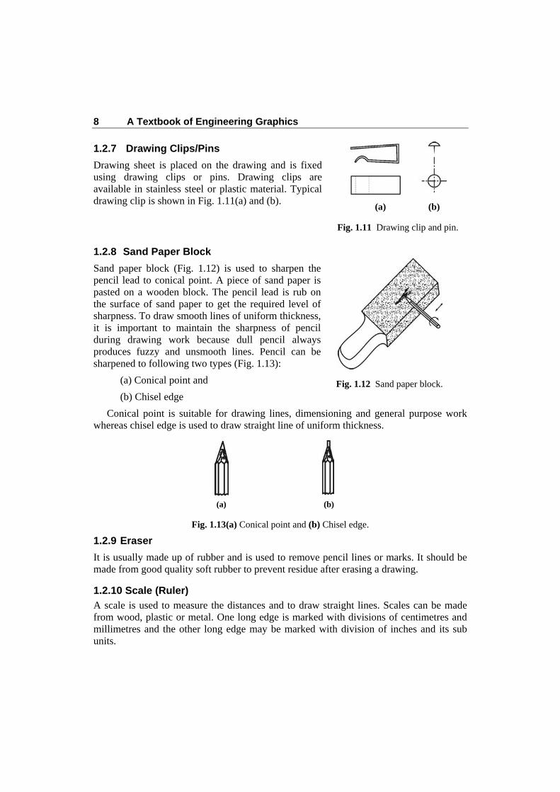
1.2.7 Drawing Clips/Pins
Drawing sheet is placed on the drawing and is fixed using drawing clips or pins. Drawing clips are available in stainless steel or plastic material. Typical drawing clip is shown in Fig. 1.11(a) and (b).
1.2.8 Sand Paper Block
Sand paper block (Fig. 1.12) is used to sharpen the pencil lead to conical point. A piece of sand paper is pasted on a wooden block. The pencil lead is rub on the surface of sand paper to get the required level of sharpness. To draw smooth lines of uniform thickness, it is important to maintain the sharpness of pencil during drawing work because dull pencil always produces fuzzy and unsmooth lines. Pencil can be sharpened to following two types (Fig. 1.13):
(a) Conical point and
(b) Chisel edge
Conical point is suitable for drawing lines, dimensioning and general purpose work whereas chisel edge is used to draw straight line of uniform thickness.
(a) (b)
Fig. 1.13(a) Conical point and (b) Chisel edge.
1.2.9 Eraser
It is usually made up of rubber and is used to remove pencil lines or marks. It should be made from good quality soft rubber to prevent residue after erasing a drawing.
1.2.10 Scale (Ruler)
A scale is used to measure the distances and to draw straight lines. Scales can be made from wood, plastic or metal. One long edge is marked with divisions of centimetres and millimetres and the other long edge may be marked with division of inches and its sub units.
(a) (b)
Fig. 1.11 Drawing clip and pin.
Fig. 1.12 Sand paper block.

Introduction 9
1.2.11 Engineer’s Scale
Drawing of bigger objects can not be prepared with true dimensions. It is always required to reduce the actual dimensions to fit the normal paper size. However, full scale drawing can also be prepared for smaller objects such as watch components, small electronic circuits etc. Engineer’s scale can be made from wood, celluloid, card board or metal. On both sides divisions are marked with the reduced or enlarged lengths in a particular ratio. For example, full size scale (1:1) on one side and half size scale (2:1) on other side. As per BIS standard full size scale is designated as 1:1. Reducing scales may be with 1:2, 1:5, 1:10, 1:20, 1:25, 1:50, 1:100 and enlarging scale may be with 10:1, 5:1 and 2:1. The ratio 1:10 means that 1 cm on drawing will represent 10 cm actual distance. Engineer’s scales are used to prepare drawings with either enlarging or reducing size.
1.2.12 French Curves
French curves are shown in Fig. 1.14. They are made of transparent plastic or celluloid and are used to draw curved lines or arcs of any irregular shape or of desired curvature.
Fig. 1.14 French curves.
1.2.13 Protractor
Protractor is also made of transparent celluloid material. It is used to measure angles or to construct angles of any required degree. A protractor is shown in Fig. 1.15.

10 A Textbook of Engineering Graphics
Fig. 1.15 Protractor
1.2.14 Drawing Sheet
Now-a-days, drawing sheet/paper is available in different quality and sizes. The quality of drawing work and its appearance depends on the quality of drawing sheet. A good quality sheet will not leave black marks while erasing. An ideal drawing sheet should meet the following requirements:
(a) It should be tough and strong.
(b) It should have good erasing quality so that, if eraser is used its fibres should not come out.
(c) It should be super white in colour.
As per recommendation of Bureau of Indian standards (BIS), standard size of drawing sheets can be designated as shown in Table 1.2.
Table 1.2
S. No. Designation Size of Drawing Sheet
Length (mm) × Width (mm) 1 A0 1189 × 841
2 A1 841 × 594
3 A2 594 × 420
4 A3 420 × 297
5 A4 297 × 210
6 A5 210 × 148
7 A6 148 × 105
8 A7 105 × 74
9 A8 74 × 52

Introduction 11
1.2.15 Pencil Sharpener
Pencil sharpener is used to sharpen the pencil. It consists of a cutting blade, fitted inside its body. It removes the wood around the lead and produces conical end leaving the lead exposed. The lead can be prepared as conical point or chisel edge.
1.2.16 Handkerchief or Towel Cloth
Handkerchief or towel cloth of suitable size is used as a duster. Before starting the drawing work, all the instruments and accessories should be cleaned thoroughly using duster or towel cloth. This can also be used for sweeping away the crumbs which are formed due to erasing with rubber or eraser.
1.3 Lines Engineering drawing of any object is systematic combination of lines of different types. Different types of lines are considered as alphabet of this language. As per Indian standards (SP 46-1988) types of lines and their applications are presented in Table 1.3. Figure 1.16 illustrates use of various lines.
Table 1.3
Line Description Applications
A Continuous
thick
- Visible outlines
- Visible edges
B Continuous thin
- Imaginary lines of intersection
- Dimension lines
- Projection lines
- Leader lines
- Hatching
- Outlines of revolved section in place
- Short centre lines
C Continuous thin free hand - Limits of partial or interrupted views and section, if the limit is not a chain thin
D Continuous thin (straight with zigzags)
- Long break line
E Dashed thick - Hidden outlines
- Hidden edges
F Dashed thin - Hidden outlines
- Hidden edges
G Chain thin
- Centre line
- Lines of symmetry
- Trajectories
Table 1.3 Contd...

12 A Textbook of Engineering Graphics
Line Description Applications
H Chain, thick at ends and
change of direction
- Cutting planes
J Chain thick - Indication of lines or surfaces to which a
special requirement applies
K Chain thin Double
Dashed
- outlines of adjacent part
- Alternative and extreme positions of
moving parts
- Centroidal lines
- Initial outlines prior to forming
- Parts situated in front of the cutting plane.
Fig. 1.16 Use of various lines.
1.4 Lettering
Lettering is used to write titles, dimensions and other necessary information on a drawing. All letters should have uniform height and width and should be legible, simple and easy to write. Lettering should be done with dark pencil such as 2H or HB. The lettering should be done in such a manner that it should take minimum time without the use of drawing instruments. Letters used for engineering drawing may broadly be classified into two types i.e., single stroke letters and gothic letters.

Introduction 13
1.4.1 Single Stroke Letters
Single stroke letters are simplest form of letters and are used to write titles, dimensions, notes and other information on a drawing. Lettering using single stroke letters has been recommended by Bureau of Indian Standards (BIS) and described in IS:9609-1990. The word “single stroke” indicates that the thickness of lines used in letters should be such as obtained in single stroke of pencil. It does not mean that letter written in single stroke without lifting the pencil. The single stroke letters may be of two types e.g., vertical and inclined letters.
The vertical letters are used for general purpose lettering in engineering drawing. Height to width ratio of such letters varies. But for all practical purposes the letters with height to width ratio may be taken as 7:5 or 6:5 for all capital letters except I, J, L, M and W. For M and W the suitable ratio is 10:8 and for I, this ratio is taken as 10:2. For numerals such ratio may be taken as 7:4 or 6:3. Single stroke vertical upper and lower case letters and numerals are shown in Fig. 1.17. The inclined/italics letters are written
Fig. 1.17 Single stroke vertical letters and numerals.
14 A Textbook of Engineering Graphics
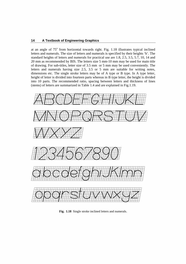
at an angle of 75o from horizontal towards right. Fig. 1.18 illustrates typical inclined letters and numerals. The size of letters and numerals is specified by their heights ‘h’. The standard heights of letters and numerals for practical use are 1.8, 2.5, 3.5, 5.7, 10, 14 and 20 mm as recommended by BIS. The letters size 5 mm-10 mm may be used for main title of drawing. For sub-titles, letter size of 3.5 mm or 5 mm may be used conveniently. The letters and numerals having size 2.5, 3.5 or 5 mm are suitable for writing notes, dimensions etc. The single stroke letters may be of A type or B type. In A type letter, height of letter is divided into fourteen parts whereas in B type letter, the height is divided into 10 parts. The recommended ratio, spacing between letters and thickness of lines (stems) of letters are summarized in Table 1.4 and are explained in Fig.1.19.
Fig. 1.18 Single stroke inclined letters and numerals.

Introduction 15
(a)
(b) (c) Fig. 1.19
Table 1.4 Standard dimensions for A type and B type letters
Types
of
Letters
Height
of
Upper
Case
Letters
(h)
Height
of
Lower
Case
letters
(c1)
Tails
of
Lower
Case
Letters
(c2)
Stem
of
Lower
Case
Letters
(C3)
Spacing
Between
Characters
(a)
Minimum
Spacing
Between
Base Lines
for Upper
Case and
Lower Case
Letters
(b1)
Minimum
Spacing
Between
Base Lines
for Upper
Case
Letters
(b2)
Minimum
Spacing
Between
Words
( e)
Line
Width
(d)
Type A 14h
14
10h
14
4h
14
4
h14
2
h14
21
h14
17
h14
6
h14
1
h14
Type B 10h
10
7h
10
3h
10
3h
10
2h
10
15
h10
13
h10
6
h10
1
h10
c 1
c 3 b
1
b2
Base Line
Base Line
h
a e c 2
d

16 A Textbook of Engineering Graphics
1.4.2 Gothic Letters
When the stem of letters are given more thickness, such letters are called as gothic letters. These letters are used for writing the main title for ink drawing. Thickness of stem may be taken as 1/5th to 1/10th of the height of letters.
1.4.3 General Rules for Lettering
(a) Select the size of letters suitable to given drawing.
(b) Draw horizontal guide lines keeping the distance between them equal to the height of letters.
(c) Width of letters may be taken equal to the height of the letter. Complete the lettering with the standard dimensions.
(d) Do not erase the guide lines.
1.5 Dimensioning
In order to describe any object or drawing technically, it is required to show all the measurements on it. Placing details such as length, breadth, height, thickness of objects, diameter/radius of holes, slots, grooves etc., is known as dimensioning. The dimensioning should be very clear, legible and easy to understand by engineers, technicians etc.
1.5.1 Dimensioning Terminology
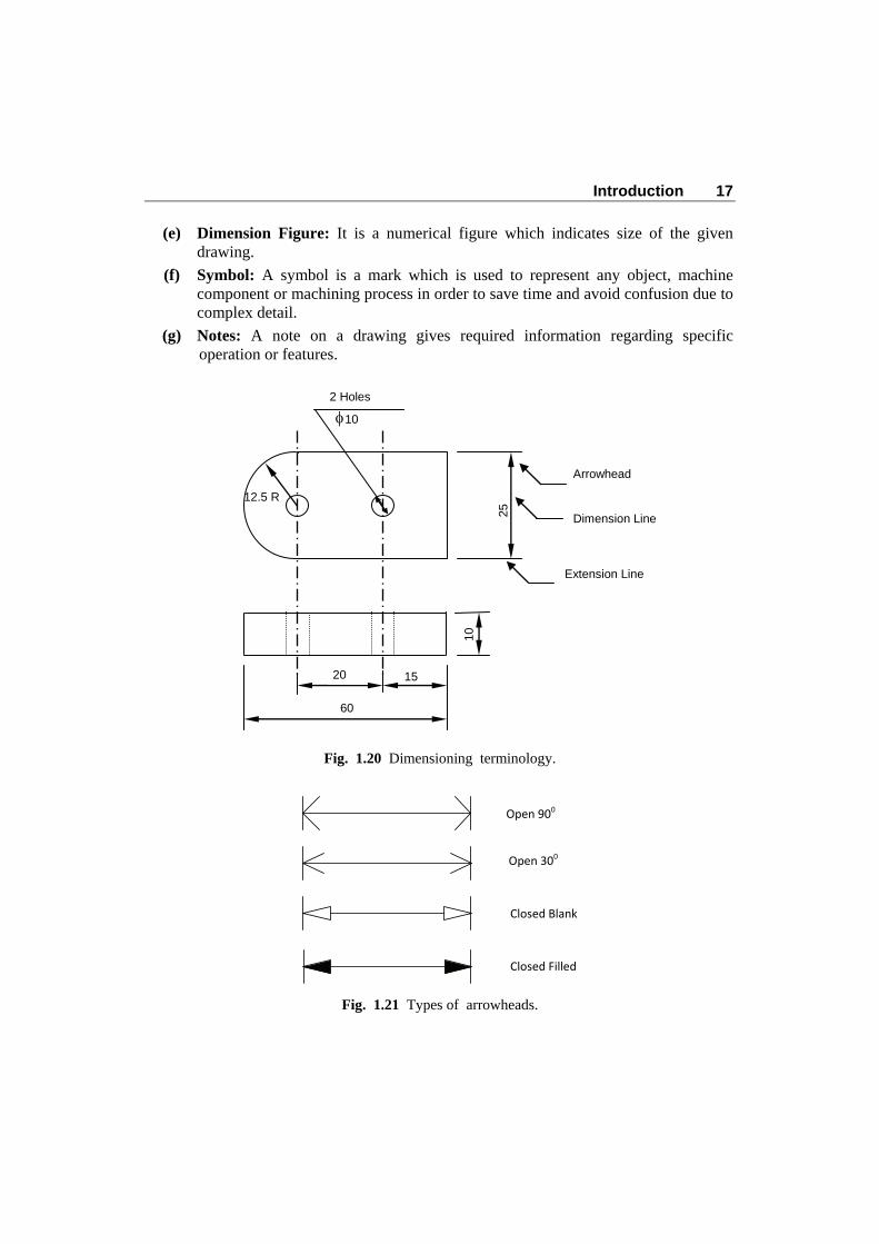
Various terms used for dimensioning (Refer Fig. 1.20) are explained as below:
(a) Dimension Line: Dimension line is a thin continuous line used to indicate measurement. The numerical value of a measurement is placed near the middle of this line.
(b) Extension Line: Extended line beyond the outline of any object is known as extension line. The extension line is drawn in such a way that dimension line remains perpendicular to it.
(c) Arrowhead: Arrowheads are placed at the extreme ends of a dimension line in a direction opposite to each other. These arrowheads are used to terminate dimension line. Different types of arrowheads have been recommended by BIS (as shown in Fig. 1.21) such as open 90o, open 30o, closed blank, closed filled etc. The length of an arrowhead is kept 3 times its breadth. The length of an arrowhead is kept about 3 mm for most of the drawings.
(d) Leaders or Pointer Line: Leader lines are thin continuous line which is used to indicate dimensions, notes etc., outside the drawing. Leaders are drawn at any desired angle such as 30o, 45o or 60o. Leaders should not be drawn as vertical, horizontal or curved lines.
Introduction 17
(e) Dimension Figure: It is a numerical figure which indicates size of the given drawing.
(f) Symbol: A symbol is a mark which is used to represent any object, machine component or machining process in order to save time and avoid confusion due to complex detail.
(g) Notes: A note on a drawing gives required information regarding specific operation or features.
Fig. 1.20 Dimensioning terminology.
Fig. 1.21 Types of arrowheads.
12.5 R 25
2 Holes
� 10
10
15 20
60
Arrowhead
Dimension Line
Extension Line
Open 900
Open 300
Closed Blank
Closed Filled
18 A Textbook of Engineering Graphics
1.5.2 System of Dimensioning
Dimensions are placed in such a manner that it is clear and readable. There are two recommended systems for placing dimensions on a drawing as follows:
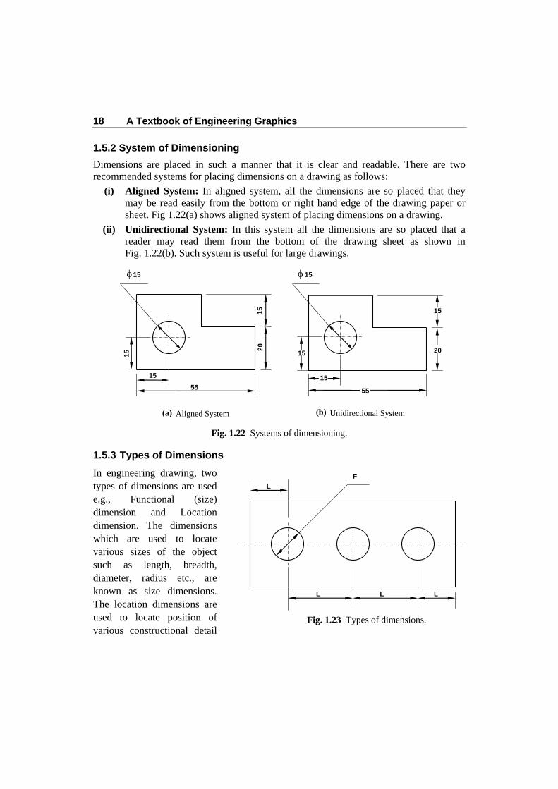
(i) Aligned System: In aligned system, all the dimensions are so placed that they may be read easily from the bottom or right hand edge of the drawing paper or sheet. Fig 1.22(a) shows aligned system of placing dimensions on a drawing.
(ii) Unidirectional System: In this system all the dimensions are so placed that a reader may read them from the bottom of the drawing sheet as shown in Fig. 1.22(b). Such system is useful for large drawings.
Fig. 1.22 Systems of dimensioning.
1.5.3 Types of Dimensions
In engineering drawing, two types of dimensions are used e.g., Functional (size) dimension and Location dimension. The dimensions which are used to locate various sizes of the object such as length, breadth, diameter, radius etc., are known as size dimensions. The location dimensions are used to locate position of various constructional detail
� 15
55
15
1
5 2
0
15
� 15
55
15
15
15
20
(a) Aligned System (b) Unidirectional System
Fig. 1.23 Types of dimensions.
F
L L L
L
(a) (b)

Introduction 19
within the object. The functional and location dimensions are represented by letters ‘F’ and ‘L’ respectively as shown in Fig. 1.23.
1.5.4 General Rules of Dimensioning
Dimensions should be clear, readable and easy to understand.
1. All dimensions should be placed outside the view. Marking of dimensions inside the view is permitted only when it is not possible to place them outside the view.
2. Dimension lines should be drawn at least 8 mm away from the visible outlines of the view.
3. Dimensional value must be placed near the middle of dimension line. If it is not possible to do so then, it can be placed above the extended portion of the dimension line. Arrowheads are usually drawn within the limit of dimension line. If distance between two extension lines is not sufficient then dimensions may be placed as shown in Fig.1.24.
30
5
510
Fig. 1.24
4. Dimension of a particular feature should not be repeated not only in the same view but also in another view of the same object.
5. As far as possible every dimension should be marked on a drawing but none of dimension should be repeated.
6. Two dimension lines should not cross each other or dimension line should not intersect any other line of the drawing.
7. An outline of an object should not be used as a dimension line.
8. Centre line of any object should not be used as an extension line for placing dimensions.
9. As far as possible, aligned system of dimensioning should be used.
Method of placing dimensions to common features is presented in Fig. 1.25.

20 A Textbook of Engineering Graphics
Fig. 1.25
Object/ Feature Illustration
� 20
� 20
� 20
200
200
S �20 S �20
SQ 10
�20 �20
45o 245o
90o
25
35
50
Taper 1:5
Diameter of Circle
Angle
Spherical Object
Square Object
Chamfer
Counter Shunk
Taper (D-d)/L
Introduction 21
1.6 General Preparation before Commencing Engineering Drawing
1. Arrange all drawing instruments required, clean them and check for their accuracy.
2. Design of drawing table and chair should facilitate comfortable sitting and proper movement of body. A bed arrangement will lead to early tiredness which may affect accuracy of work.
3. Natural air circulation and sufficient illumination in drawing hall or room must be ensured.
4. Keep the required instruments and accessories near the drawing table.
5. Fix the required size of drawing sheet on a drawing board with the help of drawing clips and clamp the mini drafter on the board in such a manner that its scale can move covering maximum area of drawing sheet.
6. Sharp the pencils of required grades to prepare their leads ready for use.
7. Draw margin lines and title block. The title block is placed in the lower right hand corner of drawing sheet. As per BIS, the recommended size of title block is 185 × 65 mm. A title block must contain following information.
(a) Title of drawing
(b) Drawing number
(c) Name of firm
(d) Scale
(e) Symbol indicating method of projection
(f) Date, name of person, checked by, approved by etc.
A typical layout of drawing sheet and a title block suitable for engineering students for class room practice, are presented in Fig. 1.26 and 1.27 respectively.
1.7 Geometrical Constructions
1.7.1 Basic Constructions
Engineering drawing of various objects requires basic knowledge of some geometrical constructions. Students are advised to understand the principles of geometrical constructions because it is the prerequisite for solving various problems of engineering drawing. Basic constructions very often required during drawing work are explained with the help of following examples.

22 A Textbook of Engineering Graphics
Fig. 1.26 Layout of drawing sheet.
Fig. 1.27 Title block.
150
NAME OF THE INSTITUTE/ COLLEGE NAME
CLASS
ROLL NO.
DATE OF COMM.
DATE OF SUBM.
SCALE
TITLE OF DRAWING
SHEET NO.
GRADE
CHECKED BY
60
10
Drawing space
10
20
Filing Margin
Title Block
10
Edge

Introduction 23
Problem 1.1 (Fig.1.28): Draw a perpendicular bisector of a 60 mm long straight line. Construction (Fig. 1.28):
1. First of all draw a straight line AB, 60 mm long.
2. Set compass to a length more than half the length of AB.
3. Keep the needle leg of the compass at point A and draw two arcs above and below line AB.
4. Now keeping the same length in compass, keep its needle leg at B. Draw two arcs above and below the line AB to intersect previous arcs at points C and D.
5. Draw a line passing through points C and D, which is the required perpendicular bisector of AB. The point O divides the line AB in two equal parts.
Problem 1.2 (Fig. 1.29): Divide a straight line AB 70 mm long into six equal parts. Construction (Fig.1.29):
1. Draw a 70 mm long straight line AB.
2. Draw an another line AC inclined to AB with any suitable angle.
3. Mark six division points as 1', 2 ', 3 ', .... 6 ' on AC with the help of a divider or a compass. Join last division point (6΄) to end point B.
4. Draw lines through 5 ', 4', 3', 2' and 1' parallel to line B6' meeting the line AB at 5,4,3,2 and 1 respectively.
5. Thus AB is divided into six equal parts.
Fig. 1.29
Fig. 1.28
A B
C
D
O
1 2 3 4 5 6 A B
1'
2'
3'
4'
5'
6'
C
24 A Textbook of Engineering Graphics
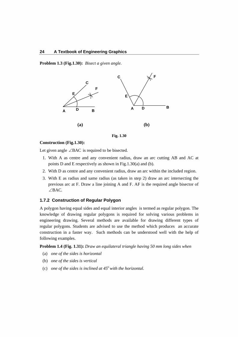
Problem 1.3 (Fig.1.30): Bisect a given angle.
Fig. 1.30
Construction (Fig.1.30):
Let given angle BAC is required to be bisected.
1. With A as centre and any convenient radius, draw an arc cutting AB and AC at points D and E respectively as shown in Fig.1.30(a) and (b).
2. With D as centre and any convenient radius, draw an arc within the included region.
3. With E as radius and same radius (as taken in step 2) draw an arc intersecting the previous arc at F. Draw a line joining A and F. AF is the required angle bisector of
BAC.
1.7.2 Construction of Regular Polygon
A polygon having equal sides and equal interior angles is termed as regular polygon. The knowledge of drawing regular polygons is required for solving various problems in engineering drawing. Several methods are available for drawing different types of regular polygons. Students are advised to use the method which produces an accurate construction in a faster way. Such methods can be understood well with the help of following examples.
Problem 1.4 (Fig. 1.31): Draw an equilateral triangle having 50 mm long sides when (a) one of the sides is horizontal (b) one of the sides is vertical
(c) one of the sides is inclined at 45o with the horizontal.
A B
C
E
D
C
E
DA B
(a) (b)
F
F

Introduction 25
Fig. 1.31
Construction (Fig.1.31):
1. Draw a horizontal straight line AB, 50 mm long as shown in Fig. 1.31(a).
2. With A as centre and radius equal AB, draw an arc above line AB.
3. With B as centre and radius equal to AB, draw another arc to intersect previous arc at C.
4. Join A to C and B to C. The triangle ABC is required equilateral triangle.
5. Similarly draw the triangles for other positions of side AB as shown in Figs. 1.31 (b) & (c).
Problem 1.5 (Fig.1.32): Construct a square with 45 mm long sides if (a) one of the sides is horizontal (b) one of the sides is inclined 30o to horizontal. (c) two sides are equally inclined (45o) with horizontal
Fig. 1.32
B
(b) (c) (a)
BA
C
B
A
A
C
C
60 o
60 o
60 o
60 o
60 o
45 o 60o
AB=BC=CA= 50 mm
(a)
45 B A
C D
90 o
30 o
90 o 45 o 45 o
90 o
A A
B
B CC
DD
(c) (b)

26 A Textbook of Engineering Graphics
Construction (Fig.1.32):
1. Draw a horizontal straight line AB, 45 mm long as shown in Fig.1.32(a).
2. Draw perpendicular lines at A and B.
3. With A as centre and radius equal to AB, draw an arc to intersect the perpendicular at D.
4. Similarly, obtain point C on another perpendicular.
5. Join C to D. Thus, ABCD is the required square.
6. Similarly draw the squares for other positions of side AB as shown in Figs.1.32 (b) & (c).
Problem 1.6 (Fig. 1.33): Construct a square having its diagonals 60 mm long. Construction (Fig.1.33):
1. Draw a horizontal line AC, 60 mm long as diagonal of square.
2. Draw a vertical line BD, 60 mm long as perpendicular bisector of AC such that AC also bisect BD.
3. Join A, B, C and D to obtain required square.
Problem 1.7 (Fig.1.34): Draw a regular pentagon with 50 mm sides.
Fig. 1.34
Fig. 1.33
O A C
B
D
BA
CE
108o108o
50
D

Introduction 27
Construction (Fig.1.34):
1. Draw a line AB 50 mm long.
2. Draw lines BC and AE 50 mm long and inclined at 1080 with AB.
With E and C as centres and radius equal to 50 mm, draw arcs intersecting at D.
3. Join points E and C to D. ABCDE is the required pentagon.
Problem 1.8 (Fig. 1.35): Draw a regular hexagon with 50 mm sides.
Fig. 1.35
Construction (Fig.1.35):
1. Draw line AB equal to 50 mm as one of the sides of hexagon.
2. With A and B as centres and radius equal to 50 mm, draw two arcs to intersect each other at O.
3. With O as centre and radius equal to 50 mm, draw a circle passing through A and B.
4. Using compass with radius equal to 50 mm draw arcs cutting the circle at C, D, E and F.
5. Join all the points with straight lines. ABCDEF is the required hexagon.
BA
C
D
50
F
E
O
28 A Textbook of Engineering Graphics
1.7.3 General Methods for Regular Polygons
General method can be used for drawing regular polygons with any number of sides. The construction of a regular hexagon using this method is explained with the help of following problem.
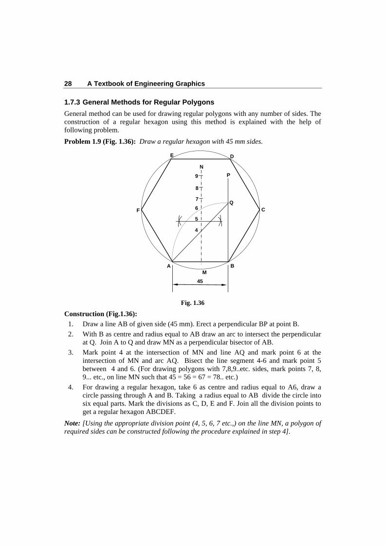
Problem 1.9 (Fig. 1.36): Draw a regular hexagon with 45 mm sides.
Fig. 1.36
Construction (Fig.1.36):
1. Draw a line AB of given side (45 mm). Erect a perpendicular BP at point B.
2. With B as centre and radius equal to AB draw an arc to intersect the perpendicular at Q. Join A to Q and draw MN as a perpendicular bisector of AB.
3. Mark point 4 at the intersection of MN and line AQ and mark point 6 at the intersection of MN and arc AQ. Bisect the line segment 4-6 and mark point 5 between 4 and 6. (For drawing polygons with 7,8,9..etc. sides, mark points 7, 8, 9... etc., on line MN such that 45 = 56 = 67 = 78.. etc.)
4. For drawing a regular hexagon, take 6 as centre and radius equal to A6, draw a circle passing through A and B. Taking a radius equal to AB divide the circle into six equal parts. Mark the divisions as C, D, E and F. Join all the division points to get a regular hexagon ABCDEF.
Note: [Using the appropriate division point (4, 5, 6, 7 etc.,) on the line MN, a polygon of required sides can be constructed following the procedure explained in step 4].
BA
C
D
45
F
E
4
5
6
N
Q
M
P
7
8
9

Introduction 29
Exercises
1. What do you understand by Engineering Drawing? Why it is known as universal language of engineers? Explain.
2. Write the names of major drawing instruments with their uses?
3. How would you draw horizontal, vertical, inclined and parallel lines with the help of mini drafter? Explain with the help of suitable diagrams.
4. Explain the use of French curves in engineering drawing?
5. Draw different types of lines used in engineering practice.
6. Write the following sentence in freehand using single stroke vertical capital letters of 10 mm height.
“Drawing is the Universal Language of Engineers”
7. Write freehand, in single stroke inclined capital letters of 10 mm height the following sentence.
“Knowledge of Engineering Drawing is Essential For Engineers”
8. Write freehand, in single stroke vertical lower case letters of 5 mm height the following sentences.
“Work is worship”.
9. Write freehand, in single stroke inclined lower case letters of 5 mm height the following sentences.
“Importance of man machine and materials in manufacturing”.
10. What is the importance of dimensioning? Explain in brief.
11. What are the aligned system and unidirectional system of dimensioning? Explain in brief.
12. With the help of neat diagram, explain dimension line, extension line and leader line?
13. Draw and explain different types of arrow head used for dimension lines?
14. Write general rules of dimensioning?
15. Illustrate the method of dimensioning the following :
(i) Diameter of Circle (ii) An angle (iii) Spherical objects (iv) Square objects (v) Holes (vi) Chamfers (vii) Countersunk hole and (viii) Taper.
16. Draw a perpendicular bisector of a 70 mm long straight line.

30 A Textbook of Engineering Graphics
17. Draw a line AB, 80 mm long and divide it into nine equal parts.
18. Draw an equilateral triangle having 40 mm long sides when
(i) one of the sides is horizontal (ii) one of the sides is vertical (iii) one of the sides is inclined at 45o with the horizontal.
19. Construct a square with 45 mm long sides if
(i) one of the sides is horizontal (ii) one of the sides is inclined 30o to horizontal (iii) Two sides are equally inclined (45o) with horizontal
20. Draw a regular pentagon with 45 mm sides.
21. Draw a regular hexagon with 55 mm sides using any two methods.