challenges of design and construction of a highway tunnel ... of design and... · challenges of...
TRANSCRIPT

Challenges of Design and Construction of a Highway Tunnel through Mixed Geology in Himalayas
R.K. Goela*, R.D. Dwivedia, G. Viswanathanb and J.S. Rathoreb
aCentral Institute of Mining & Fuel Research, Regional Centre, Roorkee, India
bChenani-Nashri Tunnelway Ltd., C/o ITNL, Patnitop, J&K, India *Corresponding Author’s E-mail: [email protected]
ABSTRACT The Government of India has entrusted the National Highway Authority of India (NHAI) with the
responsibility of four laning of Chenani to Nashri Section of NH-1A from km 89.00 to km 130.00 including 9km long bi-directional traffic tunnel with a parallel escape tunnel of 9km on BOT (annuity) basis.
The project area lies in western Himalayan region. The rock masses along the project of the Chenani-Nashri tunnel, belong to the Lower Murree formation that includes a sequence of interbedded sandstones, siltstones and claystones layers.
The tunnel behaviour classification of the rock mass has been performed by Geodata, Italy. These rock behaviour classes has been correlated with the rock mass behavior type of NATM. The supports for various behavior classes have also been designed using the numerical methods as per the requirements.
The tunnel construction work was started in August 2011 from South end and in September 2011 from North end. As expected the experience of tunneling in Himalayan mixed geology having bands of sandstone, siltstone, claystone, intermingled siltstone and claystone and sheared siltstone and claystone is not very encouraging. There have been instances of overbreaks and cracks in shotcrete support in the tunnel. Accordingly the designs have been modified. The benefits of displacements/convergence monitoring have been highlighted at the end.
Keywords: Highway Tunnel, Himalayas, NATM, Mixed Geology, Overbreak, Convergence monitoring
1. INTRODUCTION The infrastructure developmental activities have increased many-fold in India in last one and a half
decade. As a result many rail and road projects, which involves the construction of tunnels are also under different phases of construction. The new Highway link project between Udhampur and Banihal on National Highway 1A (NH-1A) in J&K state of India is one of the recent, most important Indian projects planned to connect the Kashmir valley with the rest of the Indian transportation network. Government of India has entrusted the National Highway Authority of India (NHAI) with the responsibility of four laning of Chenani to Nashri Section of NH-1A from km 89.00 to km 130.00. Apart from other engineering structures, this includes 9km long bi-directional traffic main tunnel with a parallel escape tunnel on BOT (annuity) basis.
NHAI through bidding process has awarded the road tunnel project to IL&FS Transportation Networks Limited (ITNL) as devoloper. ITNL has formed a special purpose vehicle (SPV) named Chenani-Nashri Tunnelway Limited (CNTL), the concessionaire, on design, build, finance, operate, and transfer (DBFOT) pattern. For tunnel excavation works, CNTL engaged M/s Leighton Contractors (India) Pvt Ltd. (LIN) on engineering, procurement and construction (EPC) basis who have enagaged M/s Geodata, Italy as their design and supervision consultant.
1143
Both tunnels, the main and the escape, have been planned to excavate from the two ends, south end towards Chenani and the North end towards Nashri. The tunnel construction was started in August 2011 and shall be completed by June 2016. The tunnel is expected to pass through muree formations of the Himalayas which are influenced by regional and local faults and shear zones. Design and construction of tunnel through such a complex and varying geology with a rock cover of more than 1000m is a difficult and challenging taks. The tunnel has been designed using the NATM concept.
The design methodology, in brief, and construction problems being faced so far on the basis of about nine months experience have been covered in the paper.
2. SALIENT FEATURES OF TUNNELS
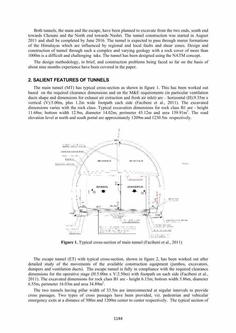
The main tunnel (MT) has typical cross-section as shown in figure 1. This has been worked out based on the required clearance dimensions and on the M&E requirements (in particular ventilation ducts shape and dimensions for exhaust air extraction and fresh air inlet) are – horizontal (H):9.35m x vertical (V):5.00m, plus 1.2m wide footpath each side (Facibeni et al., 2011). The excavated dimensions varies with the rock class. Typical excavation dimensions for rock class B1 are - height 11.68m; bottom width 12.9m, diameter 14.02m; perimeter 45.12m and area 139.91m2. The road elevation level at north and south portal are approximately 1209m and 1230.5m respectively.
Figure 1. Typical cross-section of main tunnel (Facibeni et al., 2011)
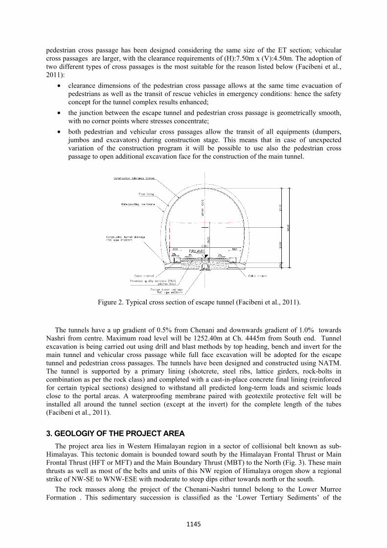
The escape tunnel (ET) with typical cross-section, shown in figure 2, has been worked out after
detailed study of the movements of the available construction equipment (jumbos, excavators, dumpers and ventilation ducts). The escape tunnel is fully in compliance with the required clearance dimensions for the operative stage (H:5.00m x V:2.50m) with footpath on each side (Facibeni et al., 2011). The excavated dimensions for rock class B1 are - height 6.15m; bottom width 5.86m, diameter 6.55m, perimeter 16.03m and area 34.89m2.
The two tunnels having pillar width of 33.5m are interconnected at regular intervals to provide cross passages. Two types of cross passages have been provided, viz. pedestrian and vehicular emergency exits at a distance of 300m and 1200m center to center respectively. The typical section of
1144
pedestrian cross passage has been designed considering the same size of the ET section; vehicular cross passages are larger, with the clearance requirements of (H):7.50m x (V):4.50m. The adoption of two different types of cross passages is the most suitable for the reason listed below (Facibeni et al., 2011):
• clearance dimensions of the pedestrian cross passage allows at the same time evacuation of pedestrians as well as the transit of rescue vehicles in emergency conditions: hence the safety concept for the tunnel complex results enhanced;
• the junction between the escape tunnel and pedestrian cross passage is geometrically smooth, with no corner points where stresses concentrate;
• both pedestrian and vehicular cross passages allow the transit of all equipments (dumpers, jumbos and excavators) during construction stage. This means that in case of unexpected variation of the construction program it will be possible to use also the pedestrian cross passage to open additional excavation face for the construction of the main tunnel.
Figure 2. Typical cross section of escape tunnel (Facibeni et al., 2011).
The tunnels have a up gradient of 0.5% from Chenani and downwards gradient of 1.0% towards
Nashri from centre. Maximum road level will be 1252.40m at Ch. 4445m from South end. Tunnel excavation is being carried out using drill and blast methods by top heading, bench and invert for the main tunnel and vehicular cross passage while full face excavation will be adopted for the escape tunnel and pedestrian cross passages. The tunnels have been designed and constructed using NATM. The tunnel is supported by a primary lining (shotcrete, steel ribs, lattice girders, rock-bolts in combination as per the rock class) and completed with a cast-in-place concrete final lining (reinforced for certain typical sections) designed to withstand all predicted long-term loads and seismic loads close to the portal areas. A waterproofing membrane paired with geotextile protective felt will be installed all around the tunnel section (except at the invert) for the complete length of the tubes (Facibeni et al., 2011).
3. GEOLOGIY OF THE PROJECT AREA
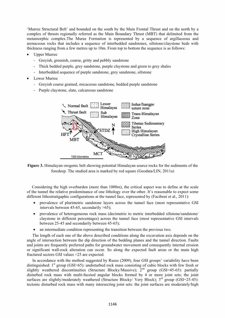
The project area lies in Western Himalayan region in a sector of collisional belt known as sub-Himalayas. This tectonic domain is bounded toward south by the Himalayan Frontal Thrust or Main Frontal Thrust (HFT or MFT) and the Main Boundary Thrust (MBT) to the North (Fig. 3). These main thrusts as well as most of the belts and units of this NW region of Himalaya orogen show a regional strike of NW-SE to WNW-ESE with moderate to steep dips either towards north or the south.
The rock masses along the project of the Chenani-Nashri tunnel belong to the Lower Murree Formation . This sedimentary succession is classified as the ‘Lower Tertiary Sediments’ of the
1145
‘Murree Structural Belt’ and bounded on the south by the Main Frontal Thrust and on the north by a complex of thrusts regionally referred as the Main Boundary Thrust (MBT) that delimited from the metamorphic complex.The Muree Formation is represented by a sequence of argillaceous and arenaceous rocks that includes a sequence of interbedded sandstones, siltstone/claystone beds with thickness ranging from a few metres up to 10m. From top to bottom the sequence is as follows: • Upper Murree
- Greyish, greenish, coarse, gritty and pebbly sandstone - Thick bedded purple, grey sandstone, purple claystone and green to grey shales - Interbedded sequence of purple sandstone, grey sandstone, siltstone
• Lower Murree - Greyish coarse grained, micaceous sandstone, bedded purple sandstone - Purple claystone, slate, calcareous sandstone
Figure 3. Himalayan orogenic belt showing potential Himalayan source rocks for the sediments of the
foredeep. The studied area is marked by red square (Geodata/LIN, 2011a)
Considering the high overburden (more than 1000m), the critical aspect was to define at the scale of the tunnel the relative predominance of one lithology over the other. It’s reasonable to expect some different lithostratigaphic configurations at the tunnel face, represented by (Facibeni et al., 2011):
• prevalence of plurimetric sandstone layers across the tunnel face (most representative GSI intervals between 45-65, secondarily >65);
• prevalence of heterogeneous rock mass (decimetric to metric interbedded siltstone/sandstone/ claystone in different percentages) across the tunnel face (most representative GSI intervals between 25-45 and secondarily between 45-65);
• an intermediate condition representing the transition between the previous two. The length of each one of the above described conditions along the excavation axis depends on the
angle of intersection between the dip direction of the bedding planes and the tunnel direction. Faults and joints are frequently preferred paths for groundwater movement and consequently internal erosion or significant wall-rock alteration can occur. So along the expected fault areas or the main high fractured sectors GSI values <25 are expected.
In accordance with the method suggested by Russo (2009), four GSI groups’ variability have been distinguished: 1st group (GSI>65): undisturbed rock mass consisting of cubic blocks with few fresh or slightly weathered discontinuities (Structure Blocky/Massive); 2nd group (GSI=45-65): partially disturbed rock mass with multi-faceted angular blocks formed by 4 or more joint sets; the joint surfaces are slightly/moderately weathered (Structure Blocky/ Very Block); 3rd group (GSI=25-45): tectonic disturbed rock mass with many intersecting joint sets: the joint surfaces are moderately/high
1146
weathered (Structure Blocky-Seamy); 4th group (GSI < 25) (Poorly interlocked, heavily broken rock mass with mixture of angular and rounded rock pieces; highly weathered joint surfaces with compact or soft fillings).
4. TUNNEL DESIGN 4.1 Excavation behaviors and correlation with NATM classes
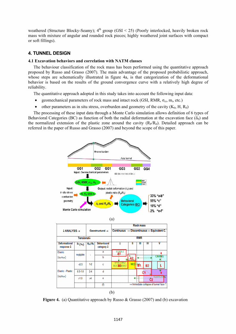
The behaviour classification of the rock mass has been performed using the quantitative approach proposed by Russo and Grasso (2007). The main advantage of the proposed probabilistic approach, whose steps are schematically illustrated in figure 4a, is that categorization of the deformational behavior is based on the results of the ground convergence curve with a relatively high degree of reliability. The quantitative approach adopted in this study takes into account the following input data:
• geomechanical parameters of rock mass and intact rock (GSI, RMR, σci, mi, etc.) • other parameters as in situ stress, overburden and geometry of the cavity (K0, H, R0)
The processing of these input data through a Monte Carlo simulation allows definition of 6 types of Behavioral Categories (BC) as function of both the radial deformation at the excavation face (δ0) and the normalized extension of the plastic zone around the cavity (RP/R0). Detailed approach can be referred in the paper of Russo and Grasso (2007) and beyond the scope of this paper.
(a)
(b)
Figure 4. (a) Quantitative approach by Russo & Grasso (2007) and (b) excavation
1147
behaviour obtained as a result of stress and geostructural analyses (Facibeni et al., 2011)
In the proposed quantitative approach, the potential geomechanical hazards occurring along the tunnel were identified on the basis of both the behavioral categorization (based on the quantification of indexes such as deformation at tunnel face and extent of the plastic zone) and the RMR system (Bieniawski, 1989)., correlated with empirical relationship with the self supporting capacity of rock masses (Fig. 4b). Starting from this matrix it’s possible to define a correlation between the rock class description (A1 to L) as per NATM qualitative approach (Rabcewicz, 1964-65 and Pacher et al., 1974).) and the behavior categories (a to f) obtained with the quantitative approach proposed by Geodata Engineering (Russo & Grasso, 2007), as shown in Table 1.
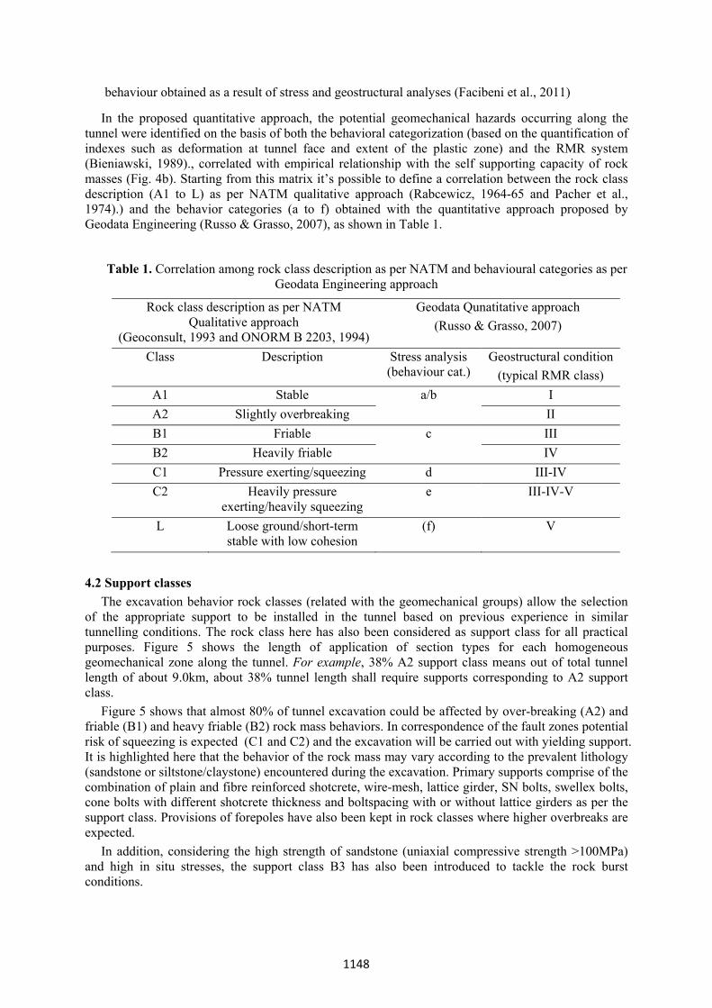
Table 1. Correlation among rock class description as per NATM and behavioural categories as per Geodata Engineering approach
Rock class description as per NATM Qualitative approach
(Geoconsult, 1993 and ONORM B 2203, 1994)
Geodata Qunatitative approach (Russo & Grasso, 2007)
Class Description Stress analysis (behaviour cat.)
Geostructural condition(typical RMR class)
A1 Stable a/b I A2 Slightly overbreaking II B1 Friable c III B2 Heavily friable IV C1 Pressure exerting/squeezing d III-IV C2 Heavily pressure
exerting/heavily squeezing e III-IV-V
L Loose ground/short-term stable with low cohesion
(f) V
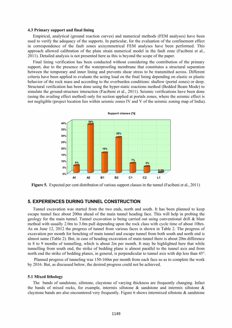
4.2 Support classes The excavation behavior rock classes (related with the geomechanical groups) allow the selection
of the appropriate support to be installed in the tunnel based on previous experience in similar tunnelling conditions. The rock class here has also been considered as support class for all practical purposes. Figure 5 shows the length of application of section types for each homogeneous geomechanical zone along the tunnel. For example, 38% A2 support class means out of total tunnel length of about 9.0km, about 38% tunnel length shall require supports corresponding to A2 support class.
Figure 5 shows that almost 80% of tunnel excavation could be affected by over-breaking (A2) and friable (B1) and heavy friable (B2) rock mass behaviors. In correspondence of the fault zones potential risk of squeezing is expected (C1 and C2) and the excavation will be carried out with yielding support. It is highlighted here that the behavior of the rock mass may vary according to the prevalent lithology (sandstone or siltstone/claystone) encountered during the excavation. Primary supports comprise of the combination of plain and fibre reinforced shotcrete, wire-mesh, lattice girder, SN bolts, swellex bolts, cone bolts with different shotcrete thickness and boltspacing with or without lattice girders as per the support class. Provisions of forepoles have also been kept in rock classes where higher overbreaks are expected.
In addition, considering the high strength of sandstone (uniaxial compressive strength >100MPa) and high in situ stresses, the support class B3 has also been introduced to tackle the rock burst conditions.
1148
4.3 Primary support and final lining Empirical, analytical (ground reaction curves) and numerical methods (FEM analyses) have been
used to verify the adequacy of the supports. In particular, for the evaluation of the confinement effect in correspondence of the fault zones axisymmetrical FEM analyses have been performed. This approach allowed calibration of the plain strain numerical model in the fault zone (Facibeni et al., 2011). Detailed analysis is not presented here as this is beyond the scope of the paper.
Final lining verification has been conducted without considering the contribution of the primary support, due to the presence of the waterproofing membrane that constitutes a structural separation between the temporary and inner lining and prevents shear stress to be transmitted across. Different criteria have been applied to evaluate the acting load on the final lining depending on elastic or plastic behavior of the rock mass and according to the overburden conditions: shallow (portal zones) or deep. Structural verification has been done using the hyper-static reactions method (Bedded Beam Mode) to simulate the ground-structure interaction (Facibeni et al., 2011). Seismic verifications have been done (using the availing effect method) only for section applied at portals zones, where the seismic effect is not negligible (project location lies within seismic zones IV and V of the seismic zoning map of India).
6%
38%
16%
28%
7%5%
0.3%0%
5%
10%
15%
20%
25%
30%
35%
40%
A1 A2 B1 B2 C1 C2 L1
Support classes [%]
Figure 5. Expected per cent distribution of various support classes in the tunnel (Facibeni et al., 2011)
5. EXPERIENCES DURING TUNNEL CONSTRUCTION Tunnel excavation was started from the two ends, north and south. It has been planned to keep escape tunnel face about 200m ahead of the main tunnel heading face. This will help in probing the geology for the main tunnel. Tunnel excavation is being carried out using conventional drill & blast method with usually 2.0m to 3.0m pull depending upon the rock class with cycle time of about 10hrs. As on June 12, 2012 the progress of tunnel from various faces is shown in Table 2. The progress of excavation per month for benching of main tunnel and escape tunnel from both south and north end is almost same (Table 2). But, in case of heading excavation of main tunnel there is about 20m difference in 8 to 9 months of tunnelling, which is about 2m per month. It may be highlighted here that while tunnelling from south end, the strike of bedding plane is almost parallel to the tunnel axis and from north end the strike of bedding planes, in general, is perpendicular to tunnel axis with dip less than 45°. Planned progress of tunneling was 150-160m per month from each face so as to complete the work by 2016. But, as discussed below, the desired progress could not be achieved. 5.1 Mixed lithology
The bands of sandstone, siltstone, claystone of varying thickness are frequently changing. Infact the bands of mixed rocks, for example, intermix siltstone & sandstone and intermix siltstone & claystone bands are also encountered very frequently. Figure 6 shows intermixed siltstone & sandstone
1149
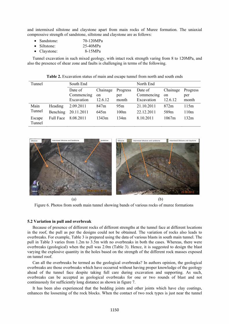
and intermixed siltstone and claystone apart from main rocks of Muree formation. The uniaxial compressive strength of sandstone, siltstone and claystone are as follows:
• Sandstone: 70-120MPa • Siltstone: 25-40MPa • Claystone: 8-15MPa
Tunnel excavation in such mixed geology, with intact rock strength varing from 8 to 120MPa, and also the presence of shear zone and faults is challenging in terms of the following.
Table 2. Excavation status of main and escape tunnel from north and south ends
Tunnel South End North End Date of Commencing Excavation
Chainage on 12.6.12
Progress per month
Date of Commencing Excavation
Chainage on 12.6.12
Progress per month
Main Tunnel
Heading 2.09.2011 847m 95m 21.10.2011 872m 115m Benching 20.11.2011 645m 100m 22.12.2011 589m 110m
Escape Tunnel
Full Face 8.08.2011 1343m 134m 8.10.2011 1067m 132m
Siltstone Intermixed Siltstone and Sandstone Sandstone Siltstone Intermixed Siltstone and claystoneIntermixed Siltstone and sandstone
(a) (b) Figure 6. Photos from south main tunnel showing bands of various rocks of muree formations
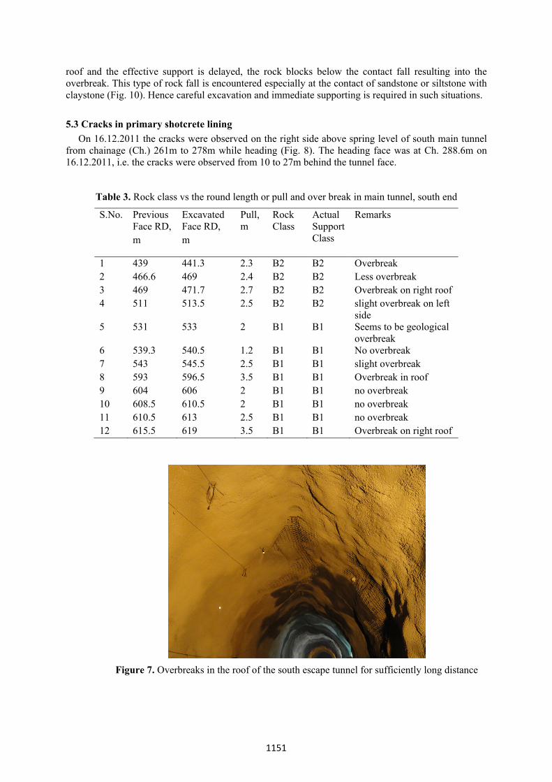
5.2 Variation in pull and overbreak Because of presence of different rocks of different strengths at the tunnel face at different locations in the roof, the pull as per the designs could not be obtained. The variation of rocks also leads to overbreaks. For example, Table 3 is prepared using the data of various blasts in south main tunnel. The pull in Table 3 varies from 1.2m to 3.5m with no overbreaks in both the cases. Whereas, there were overbreaks (geological) when the pull was 2.0m (Table 3). Hence, it is suggested to design the blast varying the explosive quantity in the holes based on the strength of the different rock masses exposed on tunnel roof. Can all the overbreaks be termed as the geological overbreaks? In authors opinion, the geological overbreaks are those overbreaks which have occurred without having proper knowledge of the geology ahead of the tunnel face despite taking full care during excavation and supporting. As such, overbreaks can be accepted as geological overbreaks for one or two rounds of blast and not continuously for sufficiently long distance as shown in figure 7. It has been also experienced that the bedding joints and other joints which have clay coatings, enhances the loosening of the rock blocks. When the contact of two rock types is just near the tunnel
1150
roof and the effective support is delayed, the rock blocks below the contact fall resulting into the overbreak. This type of rock fall is encountered especially at the contact of sandstone or siltstone with claystone (Fig. 10). Hence careful excavation and immediate supporting is required in such situations. 5.3 Cracks in primary shotcrete lining On 16.12.2011 the cracks were observed on the right side above spring level of south main tunnel from chainage (Ch.) 261m to 278m while heading (Fig. 8). The heading face was at Ch. 288.6m on 16.12.2011, i.e. the cracks were observed from 10 to 27m behind the tunnel face.
Table 3. Rock class vs the round length or pull and over break in main tunnel, south end
S.No. Previous Face RD, m
Excavated Face RD, m
Pull, m
Rock Class
Actual Support Class
Remarks
1 439 441.3 2.3 B2 B2 Overbreak 2 466.6 469 2.4 B2 B2 Less overbreak 3 469 471.7 2.7 B2 B2 Overbreak on right roof 4 511 513.5 2.5 B2 B2 slight overbreak on left
side 5 531 533 2 B1 B1 Seems to be geological
overbreak 6 539.3 540.5 1.2 B1 B1 No overbreak 7 543 545.5 2.5 B1 B1 slight overbreak 8 593 596.5 3.5 B1 B1 Overbreak in roof 9 604 606 2 B1 B1 no overbreak 10 608.5 610.5 2 B1 B1 no overbreak 11 610.5 613 2.5 B1 B1 no overbreak 12 615.5 619 3.5 B1 B1 Overbreak on right roof
Figure 7. Overbreaks in the roof of the south escape tunnel for sufficiently long distance
1151

On 23.1.2012 more cracks have been reported on the right side roof at Ch. 335m, 375m and 385m along spring level. All the cracks were in the right side from the tunnel crown and up to the spring level (Fig. 9). Though towards left side there is escape tunnel, why the cracks appeared on the right side and not on the left side? It is evident from figures 9 & 10 that the shotcrete cracked at the sheared contact of claystone and siltstone and cracks travelled towards the claystone expsoures. The primary supports here were as per support class B1, which has been obtained mainly considering the exposure of siltstone, which is stronger than claystone. The primary supports were 50mm thick sealing shotcrete, 5m long SN bolts at a spacing of 2.0m center to center; wire mesh and 100mm thick second layer of shotcrete. Subsequent numerical analysis has also revealed more strains in the claystone because of shear failure. The supports have been further strengthened, locally in the affected zone, with 9.0m long rock bolts and another 100mm thick shotcrete layer. The displacement/convergence of tunnel roof are being monitored continuously as discussed in section 5.4. Because of this behaviour of claystone, it has been suggested that the support class for the weakest rock exposed in the tunnel roof shall be obtained separately.
Siltstone claystone
Figure 8. Cracks in shotcrete above spring level in south main tunnel around ch. 261m to 278m
Figure 9. Claystone having sheared contact with siltstone at south main tunnel face ch. 261m
5.4 Monitoring Since the tunnels are being constructed using NATM, the monitoring is an important aspect for safe construction of tunnels. Systematic tunnel monitoring by fixing bireflex targets for tunnel displacement/convergence is being carried out in the tunnels for better understanding of rock mass-tunnel support interaction. The convergence targets are fixed at a regular interval of 50m or as and when required on the basis of the ground condition/geology. In addition, it is also planned to install multi-point borehole extensometers as and when required. M/s Geodata, Italy has the responsibility of readings/observations and analysis of readings. A dual level action plan for remedial measures is suggested as follows (Geodata/LIN, 2011b): (i) Attention level: is a percentage of the predicted deformation. On exceeding this level/limit of
convergence the frequency of readings will be increased in order to get the deformation speed. This trigger limit is set to study the deformation trends more closely and take countermeasures if the deformation remains continue with the same speed to the alarm limit. The attention level/limit, in general, is 80% of alarm level/limit.
(ii) Alarm level: the complete expected deformation from the design (coincide with the latest support section that will support the reached displacement and stress). Crossing of this limit will start procedure for actions and countermeasures.
Convergence limits determined for Chenani-Nashri tunnels are given in Table 4 (Geodata/LIN, 2011b). Displacement limit is one-half of convergence limit.
1152
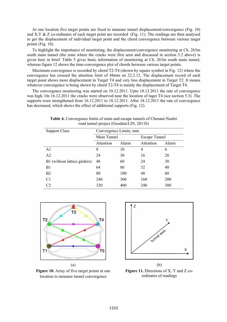
At one location five target points are fixed to measure tunnel displacement/convergence (Fig. 10) and X,Y & Z co-ordinates of each target point are recorded (Fig. 11). The readings are then analysed to get the displacement of individual target point and the chord convergence between various target points (Fig. 10). To highlight the importance of monitoring, the displacement/convergence monitoring at Ch. 263m south main tunnel (the zone where the cracks were first seen and discussed in section 5.2 above) is given here in brief. Table 5 gives basic information of monitoring at Ch. 263m south main tunnel, whereas figure 12 shows the time-convergence plot of chords between various target points. Maximum convergence is recorded by chord T2-T4 (shown by square symbol in Fig. 12) where the convergence has crossed the attention limit of 48mm on 22.2.12. The displacement record of each target point shows more displacement in Target T4 and very less displacement in Target T2. It means whatever convergence is being shown by chord T2-T4 is mainly the displacement of Target T4. The convergence monitoring was started on 10.12.2011. Upto 18.12.2011 the rate of convergence was high. On 16.12.2011 the cracks were observed near the location of taget T4 (see section 5.3). The supports were strengthened from 16.12.2011 to 18.12.2011. After 18.12.2011 the rate of convergence has decreased, which shows the effect of additional supports (Fig. 12).
Table 4. Convergence limits of main and escape tunnels of Chenani-Nashri road tunnel project (Geodata/LIN, 2011b)
Support Class Convergence Limits, mm Main Tunnel Escape Tunnel Attention Alarm Attention Alarm
A1 8 10 4 6 A2 24 30 16 20 B1 (without lattice girders) 48 60 24 30 B1 64 80 32 40 B2 80 100 48 60 C1 240 300 160 200 C2 320 400 240 300
(a) (b)
Figure 10. Array of five target points at one location to measure tunnel convergence
Figure 11. Directions of X, Y and Z co-ordinates of readings
1153
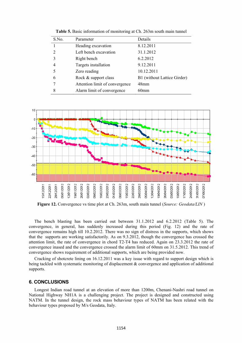
Table 5. Basic information of monitoring at Ch. 263m south main tunnel
S.No. Parameter Details 1 Heading excavation 8.12.2011 2 Left bench excavation 31.1.2012 3 Right bench 6.2.2012 4 Targets installation 9.12.2011 5 Zero reading 10.12.2011 6 Rock & support class B1 (without Lattice Girder) 7 Attention limit of convergence 48mm 8 Alarm limit of convergence 60mm
Figure 12. Convergence vs time plot at Ch. 263m, south main tunnel (Source: Geodata/LIN )
The bench blasting has been carried out between 31.1.2012 and 6.2.2012 (Table 5). The convergence, in general, has suddenly increased during this period (Fig. 12) and the rate of convergence remains high till 10.2.2012. There was no sign of distress in the supports, which shows that the supports are working satisfactorily. As on 9.3.2012, though the convergence has crossed the attention limit, the rate of convergence in chord T2-T4 has reduced. Again on 23.3.2012 the rate of convergence inased and the convergence crossed the alarm limit of 60mm on 31.5.2012. This trend of convergence shows requirement of additional supports, which are being provided now. Cracking of shotcrete lining on 16.12.2011 was a key issue with regard to support design which is being tackled with systematic monitoring of displacement & convergence and application of additional supports. 6. CONCLUSIONS Longest Indian road tunnel at an elevation of more than 1200m, Chenani-Nashri road tunnel on National Highway NH1A is a challenging project. The project is designed and constructed using NATM. In the tunnel design, the rock mass behaviour types of NATM has been related with the behaviour types proposed by M/s Geodata, Italy.
1154
The tunnel is being constructed through the challenging Himalayan geology having weak, jointed, and sheared beds of sandstone, siltstone, claystone etc. of varying thickess. As per the experience of about 4000m tunnelling in 10 months, some of the problems, like cracking of shotcrete support, overbreaks, have cropped-up. These problems helped in further enhancement of knowledge, for example, while excavating the bedded strata of different strengths, it is important to take care of strength of the rock in the blast designs, specially for overt blasting. Similarly, in mixed geology, the support class shall also be obtained for different rocks exposed on the roof of the tunnel. The monitoring of tunnel displacement/convergence is an important aspect to check the adequacy of supports and to boost the confidence of designers and construction engineers. ACKNOWLEDGEMENT
The authors are thankful to various organisation associated with CNTL Project. The views expressed in the paper are those of authors. REFERENCES Bieniawski, Z.T., 1989,. Engineering Rock Mass Classification, John Wiley & Sons, New York, 251
p. Facibeni,L., Palomba,M., Carrieri, G., Russo, G. and Guvenc, A.H., 2011, Critical Aspects in the
Design of the Chenani-Nashri Tunnel, Third Indian Rock Conference-Indorock 2011, Oct. 13-15, Org by ISRMTT Roorkee Chapter, Roorkee, India.
Geoconsult ZT GmbH, 1993, Technical Specification for Civil Underground Tunnel Works, Prepared for the General Directorate of Highways Republic of Turkey, Austria (Referred in Karahan, E. (2010) Design of Excavation and Support Systems for the Cubukbeli Tunnel in Antalya, Masters Thesis, Dept of Mining Engineering, Graduate School of Natural and Applied Sciences, Middle East Technical University, 116 p).
Geodata/LIN, 2011a, Chenani-Nashri Tunnel: Baseline Geological Report, Doc. No. I1007-GDE-ENG-RPT-GE-003 Rev C, 20 June, 23p..
Geodata/LIN, 2011b, Chenani-Nashri Tunnel: Convergence monitoring plan and countermeasure assessment, Doc. No. I1007-GDE-ENG-RPT-PID-3001 Rev B, 27 December, 10p.
ONORM B 2203, 1994, Austrian Standard “Underground construction”, Edition 10/1994. Pacher, L., Rabcewicz, L.V., Golser, J., 1974, Zum derzeitigen der Gebirgsklassifizierung in Stollen
und Tunnelbau, Reference 1, S1-8. Rabcewicz, L.V., 1964-65, The New Austrian Tunnelling method, Water Power, London, Vol. 16, m.
11-12 and Vol. 17 n. 1. Russo, G., 2009, A new rational method for calculating the GSI, Tunnel. Underground Space Technol.
24:103-111. Russo, G. & Grasso, P., 2007, On the classification of rock mass excavation behaviour in tunnelling,
11th Congress of International Society of Rock Mechanics ISRM, Lisbon.
1155