cg-1 comb generator · metodi di misura per radioamatori. franco muzzio & c. editore, 1978,...
TRANSCRIPT

CG-1 Comb Generator by JEL
User Manual v1.0 (20-02-2016)
web: http://www.jel.gr
e-mail: [email protected]
Page of 1 15

Table of contents
Table of figures & tables
1. Generator description 42. Setup instructions 63. Applications 83.1 S-Meter verification and adjustment 83.2 Insertion loss of an attenuator or coaxial cable. 103.3 Filter performance verification 123.4 Receiver performance verification 124. Specifications 145. Disclaimer 15
Fig.1 A portion of 1MHz of the emitted spectrum, centred at 144MHz. 4Fig.2 Label with calibration data for a set of harmonics. 5Fig.2 The polarity of the battery is marked on the battery holder. 6Fig.3 Power switch polarity 7Table 1. S-Meter reading for frequencies below 30MHz 8Table 2. S-Meter reading for frequencies above 30MHz 9Fig.4a Initially the reference power level is noted 10Fig.4b Cable or attenuator insertion loss can be estimated. 11Fig.5. Testing the reception of a Degen1103 radio. 12Fig.6 Handheld receiver tested against a signal of known power. 13
Page of 2 15

Page of 3 15

1. Generator description
A comb generator is a signal generator that produces multiple harmonics of its input signal. The appearance of its spectrum content (frequency domain) resembles teeth of a comb and thus the device name. The CG-1 comb generator (patent pending) is a battery operated, low cost, wide band harmonics generator which provides a useful ‘comb’ of harmonic signals spaced every 100KHz between 100KHz and ~1.5GHz. Each signal (tone) in the produced comb has its own power level which is a result of the specific design of the product. The power level (in dBm) and the frequency accuracy of the comb signals are fixed, so if we known the power level and frequency of a set of signals, then we can use this set as a reference for experiments in the lab. Since there are thousands of signals available to choose from, we selected 16 specific signals to work with and create a useful calibrated set. The idea was to have at least one signal for every ham radio and radio broadcast band, to be used as reference in RF experiments. In the Fig.1, you can see a portion of the spectrum emitted from the generator. Notice how the harmonics are equally spaced every 100KHz.
FIG.1 A PORTION OF 1MHZ OF THE EMITTED SPECTRUM, CENTRED AT 144MHZ.
Page of 4 15

Every generator is carefully assembled, tested and calibrated in our laboratory. The calibrated set of signals is printed on the top-cover label so the user can always have those important data available at a glance. A sample unit is shown in Fig.2. The frequency and average power of sixteen harmonics is presented in tabulated format. A lot of effort and attention to details is put on the production of this product. Our goal is to offer a piece of equipment which can be surely used as a signal power reference for research in labs. The enclosure is die cast aluminium which isolates the module from external interference and keeps the noise floor as low as possible. The PCB design suits the broadband operation of the unit and offer stable performance even for the highest (calibrated) signals which fall in the microwave range of the radio spectrum. We always do our best to keep the cost at affordable levels, to make the unit attractive for the hobbyist ‘RF’ experimenter, student or the professional engineer.
FIG.2 LABEL WITH CALIBRATION DATA FOR A SET OF HARMONICS.
Page of 5 15

2. Setup instructions
The comb generator requires a 9V battery of 6LR61type or equivalent. We recommend the use of an alkaline battery for best performance. If the battery voltage is drained down ~7.5V the user must immediately replace the battery with a new one to ensure that the generator's output is within specification. To install the battery the user must remove the top cover by first removing the 4 top screws. The battery must be inserted in the provided battery holder (Fig.2) and the correct polarity must be observed. Before trying to install the battery, please make sure that the ON/OFF switch is in the OFF position. While inserting the battery, be careful not to stress the battery retaining plastic clip too much as this can result in cracking the clip.
FIG.2 THE POLARITY OF THE BATTERY IS MARKED ON THE BATTERY HOLDER.
Page of 6 15
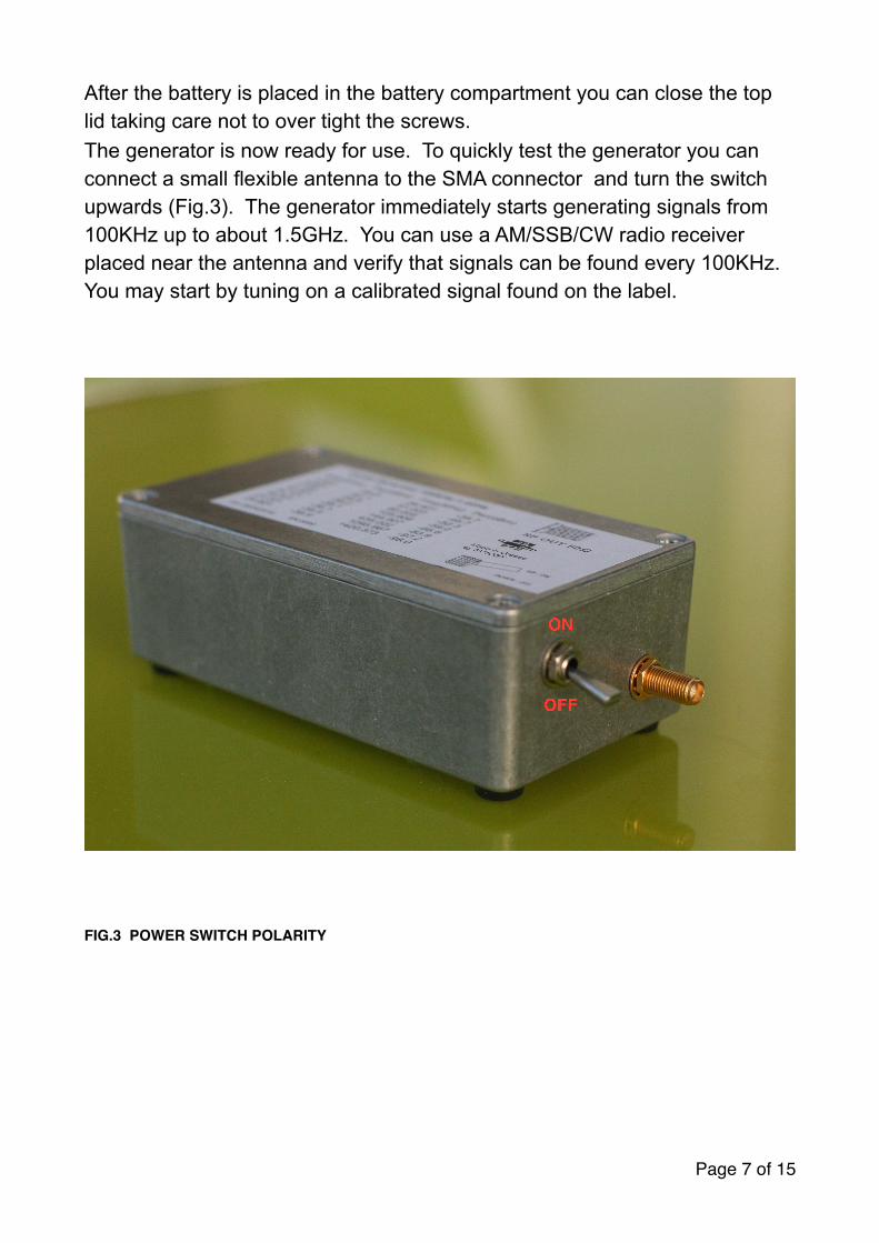
After the battery is placed in the battery compartment you can close the top lid taking care not to over tight the screws. The generator is now ready for use. To quickly test the generator you can connect a small flexible antenna to the SMA connector and turn the switch upwards (Fig.3). The generator immediately starts generating signals from 100KHz up to about 1.5GHz. You can use a AM/SSB/CW radio receiver placed near the antenna and verify that signals can be found every 100KHz. You may start by tuning on a calibrated signal found on the label.
FIG.3 POWER SWITCH POLARITY
Page of 7 15

3. Applications
3.1 S-Meter verification and adjustment
One of the most popular application of CG-1 is the verification / adjustment of the S-Meter of radio receivers (conventional or SDR). The CG-1 is connected to the input of the receiver with a small coaxial RF cable (also available from JEL). After selecting a band on the receiver, the user must consult the CG-1 label to find the appropriate signal which falls within that band. If CW mode is used, the user should zero-beat on the signal. If SSB is used, the user should tune the receiver so that the signal can be heard as a tone of 1KHz. The power (in dBm) of the selected signal can be translated to S-meter reading according to the following two tables (Table 1 & Table 2). Note that there are two tables because table 1 is referenced for frequencies below 30MHz and Table 2 for frequencies above 30MHz.
TABLE 1. S-METER READING FOR FREQUENCIES BELOW 30MHZSignal Strength (S-meter reading) Received power @ 50 ΩS1 -121dBm
S2 -115 dBm
S3 -109 dBm
S4 -103 dBm
S5 -97 dBm
S6 -91 dBm
S7 -85 dBm
S8 -79 dBm
S9 -73 dBm
S9+10dB -63 dBm
S9+20dB -53 dBm
S9+30dB -43 dBm
S9+40dB -33 dBm
S9+50dB -23 dBm
S9+60dB -13 dBm
Page of 8 15

TABLE 2. S-METER READING FOR FREQUENCIES ABOVE 30MHZ
Bibliography: Wolfgang Link, DL8FI. Metodi di misura per radioamatori. Franco Muzzio & C. editore, 1978, sezione 3.9.
The user can then check if the S-meter displays the correct signal strength. For conventional receivers, the s-meter can be adjusted with procedures that are specified by the manufacturer of the radio. In case of SDR transceivers/receivers, there is usually a software procedure to calibrate the s-meter on a signal of known strength.
If you would like to watch a video on how to adjust the S-meter of a a Softrock receiver, you can visit our website blog and go through the ‘Current product news’ post to find more information.
Signal Strength (S-meter reading) Received power @ 50 ΩS1 -141dBm
S2 -135 dBm
S3 -129 dBm
S4 -123 dBm
S5 -117 dBm
S6 -111 dBm
S7 -105 dBm
S8 -99 dBm
S9 -93 dBm
S9+10dB -83 dBm
S9+20dB -73 dBm
S9+30dB -63 dBm
S9+40dB -53 dBm
S9+50dB -43 dBm
S9+60dB -33 dBm
Page of 9 15

3.2 Insertion loss of an attenuator or coaxial cable.
It is possible to measure the insertion loss of a coaxial cable or unknown attenuator with the help of the CG-1 generator. The accuracy of measurement will be dictated by the method used for signal strength measurement. The setup is very simple and you will only need a receiver with signal strength indicator, or SDR receiver which almost always features a software S-meter. The receiver S-meter indicators could display a bar for every 3dB of signal increase or 6dB respectively. You will need to consult the user manual of your receive to find out how your s-meter behaves. Note that the impedance of the coaxial cable or the attenuator under test must always be 50Ω to match the characteristic impedance of the generator and the receiver. Also note that the CG-1 generator produces harmonics with power levels close to -30dBm (every unit has slightly different performance). Please double check that the receiving equipment is capable of handling this power level.
First connect the CG-1 to the receiver with a coaxial ‘SMA to SMA’ adapter. Fig.4a. The receiver is tuned to the band of interest and as close as possible to a calibrated signal from the CG-1 table. The signal strength of the signal is noted on the S-meter of the receiver in dBm. This is our reference Pref power level with the minimum insertion loss between the CG-1 and the receiver.
FIG.4A INITIALLY THE REFERENCE POWER LEVEL IS NOTED Page of 10 15
CG-1 comb generator
Receiver with signal strength indication
SMA to SMA adapter

Then the ‘SMA to SMA’ adapter is replaced with the coaxial cable or attenuator under test. The signal is now attenuated by our DUT (device under test), and we can check the S-meter to note the signal strength in dBm. This is Pdut
FIG.4B CABLE OR ATTENUATOR INSERTION LOSS CAN BE ESTIMATED.
The insertion loss of out DUT (device under test) is given by the formulae
Insertion loss (dB) = Pref - Pdut
Page of 11 15
CG-1 comb generator
Receiver with signal strength indication
coaxial cable or coaxial attenuator under test

3.3 Filter performance verification
Following the experiment demonstrated in section 3.2, we can verify the passband of an RF filter. The experiment steps are almost identical. We can note the signal strength of many signals of interest and once the filter is in place we can go through the same frequencies and note the attenuated figure.
3.4 Receiver performance verification
This experiment will demonstrate how we can quickly test a radio receiver. We will demonstrate two different cases. In the first case we will only verify that our receiver is capable of receiving a strong nearby signal. Then we will verify that a ham radio HT receiver receives a weak signal and displays its strength correctly.
Case 1: Attach a small antenna to the output of the CG-1 generator and turn on the generator. Place the AM,SSB or CW, receiver near the generator and tune to a desired frequency. Fine tune the receiver (+-100KHz ) so that you find an harmonic from the generator. You will hear a tone signal and you can verify that moving the frequency up or down affects the pitch of the received tone. In Fig.5 you can see a DEGEN1103 receiver placed near the CG-1, tuned to 21.202MHz. This exact frequency is one of the calibrated frequencies. As you can observe, the radio’s S-meter indicates a very strong signal.
FIG.5. TESTING THE RECEPTION OF A DEGEN1103 RADIO.
Page of 12 15

Case 2: Now we can do a second experiment. This time we can verify that the S-meter of a handheld radio (Yaesu VX8) operates correctly. For this experiment we will connect a 30dB attenuator at the output of the generator and the output of the attenuator is connected at the antenna port of the receiver. We should select a calibrated frequency from the table on the label. For this experiment the selected frequency was 435.025MHz. At this frequency the generator emits a signal at -87dBm. If we add the 30dB attenuation, it results to a signal power of -117dBm. Indeed, as shown in Fig.6, the receiver displays 4 to 5 units on the s-meter. This result was expected correct according to Table 2 in section 3.1. Note that the CG-1 generator produces harmonics with power levels close to -30dBm (every unit has slightly different performance). Please double check that the receiving equipment is capable of handling this power level.
Warning: Avoid transmitting a signal towards the CG-1. This will most surely result in permanent damage.
FIG.6 HANDHELD RECEIVER TESTED AGAINST A SIGNAL OF KNOWN POWER.
Page of 13 15

4. Specifications
• Battery operated unit. (9v battery on a battery holder for firm mounting)
• 50Ω RF Output
• Small, aluminium die cast box with reliable switch and quality SMA connector mounted on the box.
• RF shielded design to keep unwanted noise out and being able to produce very low power harmonic signals.
• Frequency range of harmonic content: Every 100KHz from 100KHz up to 1.42GHz (to cover all HF, VHF, UHF, SHF bands)
• Power level range for calibrated signals: Between -38dBm and -100dBm usually. (differs a little bit between each serialised unit)
• Power level accuracy is within 1.5dBm (each generator has its own serialised calibration sticker with its calibration data). Calibration is performed in our lab with the use of a 2cm rigid cable and calibrated instruments in our lab. The CG-1 generator is offered as a calibrated unit but this is not a NIST certification. Our calibration offers adequate accuracy for most everyday experiments, at a small fraction of the cost of professional lab grade equipment.
• Frequency stability: 20ppm crystal oscillator reference at 20MHz.
• Output signal power and frequency are guaranteed to be stable for battery voltages >7.6 volts.
• Being able to provide >100 hours of service with an alkaline 9v battery
All specifications are subject to change without notice.
Page of 14 15

5. Disclaimer
Please note that the CG-1 generator produces harmonics with power levels close to -30dBm (every unit has slightly different performance). Please double check that the receiving equipment connected to this generator is capable of handling this power level. If in doubt, use coaxial attenuators of suitable figures. Also please consider that the total power output of the generator is the combined power of all the harmonics produced!
The JEL company will not be held responsible for damage occurred to third party equipment as a result of using the CG-1 generator together with or nearby other equipment and instruments.
The CG-1 generator produces a spectrum rich in harmonics. When connected to an antenna it can produce interference to nearby equipment. Always know your laws before transmitting signals and always use the generator in a legal way. If in doubt do not connect the generator to any antenna even small ones.
Page of 15 15