cfd basics
DESCRIPTION
cfDTRANSCRIPT
22nd AIAA Applied Aerodynamics Conference AIAA-2004-4838 August 16-19, 2004, Providence, Rhode Island
This paper is declared a work of the U.S. Government and is not subject to copyright protection in the United States. American Institute of Aeronautics and Astronautics
CFD Approaches for Simulation of Wing-Body Stage Separation
Pieter G. Buning* NASA Langley Research Center, Hampton, Virginia, 23681
Reynaldo J. Gomez† NASA Johnson Space Center, Houston, Texas, 77058
and
William I. Scallion‡ NASA Langley Research Center, Hampton, Virginia, 23681
A collection of computational fluid dynamics tools and techniques are being developed and tested for application to stage separation and abort simulation for next-generation launch vehicles. In this work, an overset grid Navier-Stokes flow solver has been enhanced and demonstrated on a matrix of proximity cases and on a dynamic separation simulation of a belly-to-belly wing-body configuration. Steady cases show excellent agreement between Navier-Stokes results, Cartesian grid Euler solutions, and wind tunnel data at Mach 3. Good agreement has been obtained between Navier-Stokes, Euler, and wind tunnel results at Mach 6. An analysis of a dynamic separation at Mach 3 demonstrates that unsteady aerodynamic effects are not important for this scenario. Results provide an illustration of the relative applicability of Euler and Navier-Stokes methods to these types of problems.
I. Introduction Many recent reusable launch vehicle designs are composed of multiple bodies, including winged bodies. Interest
in developing and validating experimental and computational approaches for the design and simulation of stage separation and abort procedures for such vehicles has extended over a number of NASA programs, including 2nd-Generation Reusable Launch Vehicle, Space Launch Initiative, and Next Generation Launch Technology. This work is part of a larger effort to develop experimental and computational tools in support of the design of stage separation options for these vehicles.1
Current work on the development and validation of computational fluid dynamics (CFD) tools for the simulation of winged body stage separation is reported here. We concentrate on the prediction of aerodynamic forces of vehicles in close proximity, used for the computation of separation trajectories. Comparisons will be shown of wind tunnel and computed static forces, as well as forces from a dynamic separation simulation. This computational tool development activity includes the merging of a 6-degree-of-freedom moving body capability from the OVERFLOW-D flow solver with newer features of the standard OVERFLOW code, resulting in a more efficient static and dynamic, viscous multi-body simulation capability. Comparison with results from the Cart3D Cartesian grid Euler code illustrates both the range of applicability and the speed and ease-of-use of each method in the simulation of staging events.
Methods for using CFD to predict the aerodynamics associated with the separation of two bodies have been developed by other researchers, most notably for store separation problems in the transonic flight regime.2-4 Typically in this case the store is significantly smaller and lighter than the parent body, and as such has little aerodynamic influence on it. In contrast, this work examines a configuration where the two bodies are similar in size and mass. Research has also been done on the CFD simulation of dynamic store separation coupled with
* Aerospace Engineer, Configuration Aerodynamics Branch, Mail Stop 499, AIAA Associate Fellow. † Aerospace Engineer, Applied Aeroscience and CFD Branch, Mail Stop EG3, AIAA Member. ‡ Aerospace Engineer, Aerothermodynamics Branch, Mail Stop 408A.

American Institute of Aeronautics and Astronautics
2
movable control surfaces or even a control system.5,6 While this capability is desirable for the simulation of separation and abort maneuvers, it is not included here.
II. Configuration and Experimental Conditions In order to coordinate experimental and computational tool development, a generic two-stage configuration was
selected for development of wind tunnel proximity testing procedures and for CFD validation. This configuration uses the Langley Glide-Back Booster (LGBB) in a belly-to-belly “bimese” arrangement as shown in Figure 1. The LGBB is a generic wing-body vehicle that was developed for system analysis studies, and has been previously tested as a single body. In the bimese arrangement, one vehicle is considered the “booster” and the other the “orbiter,” though they have identical shapes. This particular configuration was chosen for separation aerodynamics testing because of the significant aerodynamic interference generated by the two vehicles’ wings being in close proximity. It is hoped that if the tools can be exercised and validated for this bimese belly-to-belly configuration, they will be applicable to other designs as well.
Experimental data used in this study are from tests run at supersonic speeds in the NASA Langley Research Center Unitary Plan Wind Tunnel (UPWT), and hypersonic speed in the Langley 20-Inch Mach 6 tunnel. An overview of the combined experimental and computational stage separation investigation is given in Ref. 1; the UPWT test program is more fully described in Ref. 7. (An earlier experimental study was conducted at the NASA Marshall Space Flight Center, at supersonic speeds.8) The test setup in these facilities has been described in the above references, but a review of the model mounting approach and flow conditions will be given here as it pertains to comparisons with computational results. In referring to the mounting of the two models, it is noted that the orbiter is always the lead vehicle, since the separation maneuver consists of the booster dropping back and away from the orbiter. It should be noted that the relative positions tested vary only in longitudinal geometry, and consider values of angle-of-attack and angle-of-attack offset between the vehicles of less than or equal to 5 deg.
In the UPWT, the booster is sting-mounted on the tunnel’s traversing support mechanism, while the orbiter is fixed to the side-wall with a swept blade strut. The strut is attached to the model in place of the vertical tail, resulting in an aerodynamic effect on both vehicles similar to the vertical tail, but with the result that the orbiter does not have a metric tail. Relative to the orbiter, the booster can translate and rotate, allowing for relative positioning between the vehicles (Figure 2). Flow conditions tested include Mach 2.3, 3.0, and 4.5, at a Reynolds number of 2.0 million per foot and a free-stream temperature of 209 deg R (at Mach 3). Model scale was 1.75% of the reference body length Lref=750 in., or 13.125 in.
Hypersonic proximity testing in the 20-Inch Mach 6 tunnel used a support system developed for previous tests, where both vehicles are sting-mounted to a common support strut. Relative aft-translation of the booster is accomplished by adjusting the upper sting, while vertical separation and relative rotation is handled by the lower (orbiter) sting (Figure 3). Significant interference effects from this support system have been noted even at Mach 6. As a result, these effects were compensated for by using force and moment data from additional runs, first with the entire support system but with the orbiter or booster model and sting removed, and second with an isolated booster or orbiter sting-mounted to a shortened strut. Mounting interference on the booster was then estimated as the difference between forces measured without the orbiter, and isolated booster forces. This booster mounting interference was determined for every booster/orbiter relative position and every angle-of-attack, and subtracted from the corresponding measured booster forces and moments. Orbiter mounting interference was estimated similarly. Thus the corrected booster and orbiter forces and moments presented here represent a combination of three different runs for each data point. Model length was 9.063 in., or 1.208% scale. A free-stream Mach number of 5.95 was tested, at a Reynolds number of 2.5 million per foot and static temperature of 113 deg R.
Figure 1. LGBB planform and bimese arrangement.

American Institute of Aeronautics and Astronautics
3
III. Computational Methods
A. Background In the engineering evaluation of unsteady maneuvers such as stage separation or aborts, the large number of
variables to be considered leads to the use of Monte Carlo techniques and integration of vehicle motion using aerodynamic databases derived from steady-state simulation (experimental or computational). Such variables include flight conditions such as altitude, speed and flight path angle, and initial separation conditions such as orientation, relative velocity, and mechanical forces and constraints. Additional aerodynamic variations may come from control surface deflections or the use of reaction control jets or separation motors.
While traditionally the majority of information in aerodynamic databases originates from wind tunnel-derived force and moment measurements, the aerodynamics of multiple bodies in close proximity allows computational methods to contribute data in a variety of situations, including cases where wind tunnel data is not available (such as very close proximity, or where an extension or refinement of the parameter space is desired after the test is completed). Corrections to the data due to wind tunnel mounting effects, differences in flow conditions between wind tunnel and flight, or plume effects may also come from CFD.
These contributions require a significant number of steady-state simulations, with variations in the relative positions of the bodies. As such, a range of computational techniques, varying in cost (or time) and fidelity is desired, but the uncertainties associated with each method must be understood. Computational methods used here include an inviscid (Euler) flow solver and a viscous (Navier-Stokes) flow solver. (In related work, an approach for automating the use of CFD in generating aerodynamic databases was developed.9 The same Euler and Navier-Stokes flow solvers were used on a single-body LGBB configuration.)
Figure 2. Schematic of LGBB bimese configuration support system in Unitary Plan Wind Tunnel.
Figure 3. LGBB bimese configuration and model support for the 20-Inch Mach 6 tunnel.

American Institute of Aeronautics and Astronautics
4
Some aspects of the separation dynamics may depend on unsteady aerodynamics, however. In order to evaluate these effects, CFD can be used to model the unsteady motion of the vehicles, simulating a dynamic separation process. While this typically takes as much computation as a steady-state case, it allows the simulation of a specific separation scenario which can then be compared to prediction of the same event from trajectory integration using the aerodynamic databases. Both the separation trajectories and the aerodynamic force contributions to the separation can be compared, allowing an assessment of unsteady effects. If significant, these effects can then be included as uncertainties in the Monte Carlo analysis.
B. Computational Codes For inviscid analyses, the Cart3D (version 1.1) code10-13 (an unstructured Cartesian grid generator and
companion Euler flow solver) has been used. Cart3D is particularly convenient for complex configurations because of its ease of use in generating grids, and is capable of producing flow solutions 10 to 100 times faster than a Navier-Stokes solver such as OVERFLOW. In supersonic flows, normal force and pitching moment can often be predicted with excellent accuracy using inviscid methods. Even axial force values are generally accurate if dominated by pressure effects, and can be easily adjusted for viscous drag. Inviscid calculations are not able to predict shock-induced flow separation, or separation from a smooth surface, for example on a wing with a rounded leading edge. In transonic flows, inviscid simulations will tend to have shock waves too far aft due to the lack of boundary layer displacement, resulting in errors in normal force and pitching moment.
For this work, a significant effort has been expended on merging two existing versions of the OVERFLOW Navier-Stokes flow solver. The resulting code is referred to as OVERFLOW 2, and includes the capabilities and features of OVERFLOW-D and OVERFLOW Version 1.8. The Chimera overset structured grid scheme is employed,14 which is well suited for multi- and moving-body applications because the grids attached to each body need only be reconnected when the bodies are moved, rather than being regenerated. The OVERFLOW-D code is the result of extensive development for a dynamic, moving-body simulation capability.15-17 This capability has been demonstrated on applications including store separation, rotorcraft, and missile problems. OVERFLOW-D includes 6-degree-of-freedom dynamic motion, automatic background grid generation, fast hole-cutting and grid connectivity, and parallel computation via the MPI (Message Passing Interface) library. In comparison, the standard OVERFLOW flow solver (versions 1.6-1.8)18,19 has been used for applications such as launch vehicles, propulsion-airframe integration, high-lift applications for subsonic transports, and hypersonic stage separation. Enhancements to this code have included grid sequencing and multigrid acceleration, low-Mach preconditioning, multiple species capability, implementation of several 1- and 2-equation turbulence models, and addition of Newton subiteration and dual time-stepping algorithms. Parallel computation has been accomplished using multi-level parallelism20 (MLP) or MPI.21 Of specific interest here is the use of multigrid and grid sequencing for faster convergence of steady-state problems, and the combination of dual time-stepping with OVERFLOW-D capabilities for more efficient simulation of moving-body problems.
A user interface for specifying moving body problems has been added to OVERFLOW 2 as well. This interface, originally developed for Cart3D, allows hierarchical body and component definitions, and setup of prescribed motion and free-flying moving body problems.22 The interface uses two text-format XML files, one to describe the association of computational grids to body components and relative placement of components, and the other to describe either time-varying body motions, or gravity, inertial properties, and applied loads and constraints. Use of this interface provides the added advantage of having a common interface with Cart3D. While the current implementation in OVERFLOW 2 is not fully general, the framework exists for expanding its capability.
IV. Results Computational solutions have been generated for supersonic and hypersonic flow conditions, and will be
compared to UPWT and 20-Inch Mach 6 wind tunnel data in this section. Results will be presented for the two regimes separately, as the types of comparisons and issues raised are different. While it is recognized that a full aerodynamic separation database includes many degrees of freedom, results in this paper are limited to longitudinal aerodynamics, including normal force, axial force, and pitching moment coefficients, resulting from vehicle offsets in X and Z (∆X and ∆Z, resp.), an angle-of-attack offset (∆α) between the vehicles, and in some cases a variation in angle-of-attack of the combined two-vehicle configuration.
A. Supersonic Flow Results As a precursor to more specific comparisons of experimental and computational data, a matrix of ∆X and ∆Z
positions was run using the Euler (inviscid) Cart3D code (Figure 4). One hundred and fifty relative positions were

American Institute of Aeronautics and Astronautics
5
run at each of the Mach numbers 2.3, 3.0, and 4.5, illustrating the usefulness of Euler methods for preliminary evaluation of a relatively large number of cases. Figure 5 shows results at Mach 3 in the form of color contour plots of normal force, axial force, and pitching moment coefficients (CN, CA, Cm), first for the booster and then for the orbiter. Clearly indicated are the relative zones of influence between the vehicles, with the orbiter returning to undisturbed (isolated) conditions over much of the ∆X-∆Z range. Also indicated are the effects of interference following Mach lines, in the +∆X/+∆Z direction for the booster and in the −∆X/+∆Z direction for the orbiter. Most effects are seen to continue with some dissipation with increased separation, though specific attention should be paid to apparent dissipation that is due more to the resolution of the matrix along with the interpolation between data points. Here linear interpolation is used in plotting the results; trajectory integration methods will use some form of interpolation as well.
A similar matrix of cases was run using the OVERFLOW flow solver at Mach 3 conditions. Force coefficients
for both computational methods and experiment are compared along a sweep in ∆X and a sweep in ∆Z, both starting from the mated position, as illustrated in Figure 6. Data comparisons are shown in Figures 7 and 8. Here both CFD methods model the vehicles in free flight, with no wind tunnel model supports included. In general, quite good
Figure 5. CN, CA, Cm at Mach 3 for booster (left) and orbiter (right), plotted as a function of ∆∆∆∆X and ∆∆∆∆Z.
Figure 4. Matrix of ∆∆∆∆X-∆∆∆∆Z positions run using Cart3D.

American Institute of Aeronautics and Astronautics
6
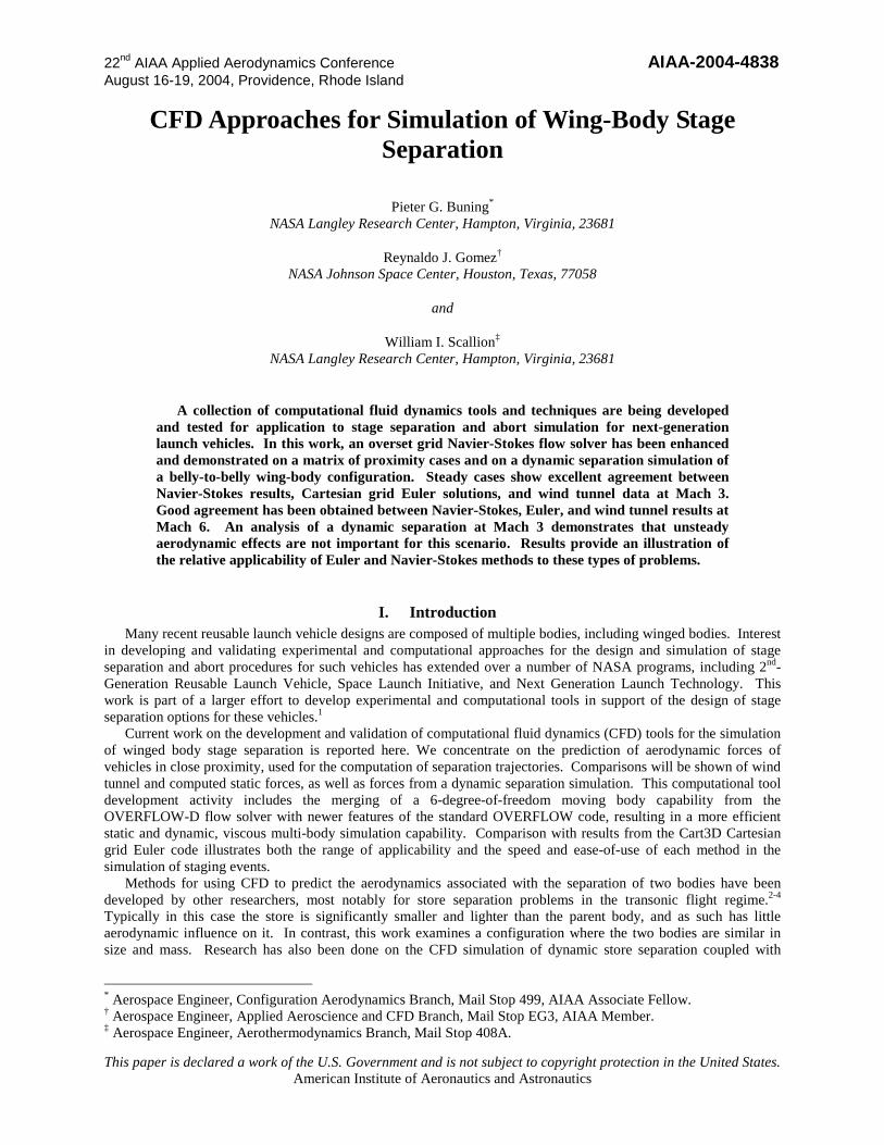
agreement is obtained between all sources. Specifically, the two computational methods agree very well, except in axial force due to the lack of a viscous drag component from the Euler code. Another notable difference is due to the lack of a metric tail for the orbiter. This shows up as a lower axial force, slightly higher normal force and slightly reduced pitching moment in the wind tunnel data. Adding the OVERFLOW-measured viscous force components to the Cart3D results, and adding the OVERFLOW-measured vertical tail components to the orbiter results from the wind tunnel can account for these two effects (Figure 9). In this case we see the level of agreement that can be obtained between computational and experimental sources. One major difference remains, that of the booster normal force during the translation aft (increasing ∆X). Clearly this is a region of large interference between the two vehicles. While this disagreement has not yet been explained, confidence in the computational results is gained by the match between viscous and inviscid computational methods.
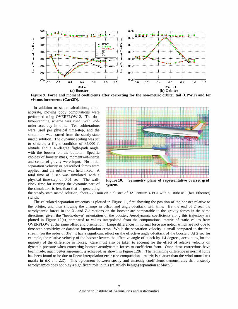
The grid system used for the OVERFLOW 2 calculations is comprised of 1.4 million points in body-fitted grids
(representing two half-vehicles), and 1.8 to 3.2 million points in automatically-generated background grids used to fill in the off-body volume (Figure 10). The full Navier-Stokes equations were modeled, including all viscous cross-terms. The Spalart-Allmaras turbulence model was employed, with boundary layers assumed to be turbulent everywhere. Initial spacing off the wall was 0.0056 in. (at reference scale), corresponding to a y+ of approximately 0.25 at UPWT conditions.
(a) Booster (b) Orbiter Figure 7. Comparison of Mach 3 wind tunnel and CFD aerodynamic forces for ∆∆∆∆X-sweep.
(a) Booster (b) Orbiter Figure 8. Comparison of Mach 3 wind tunnel and CFD aerodynamic forces for ∆∆∆∆Z-sweep.
Figure 6. Orbiter and booster relative positions for sweeps in ∆∆∆∆X and ∆∆∆∆Z, used in comparisons of aerodynamic forces.
American Institute of Aeronautics and Astronautics
7
In addition to static calculations, time-
accurate, moving body computations were performed using OVERFLOW 2. The dual time-stepping scheme was used, with 2nd-order accuracy in time. Ten subiterations were used per physical time-step, and the simulation was started from the steady-state mated solution. The dynamic scaling was set to simulate a flight condition of 85,000 ft altitude and a 45-degree flight-path angle, with the booster on the bottom. Specific choices of booster mass, moments-of-inertia and center-of-gravity were input. No initial separation velocity or prescribed forces were applied, and the orbiter was held fixed. A total time of 2 sec was simulated, with a physical time-step of 0.01 sec. The wall-clock time for running the dynamic part of the simulation is less than that of generating the steady-state mated solution, about 220 min on a cluster of 32 Pentium 4 PCs with a 100baseT (fast Ethernet) switch.
The calculated separation trajectory is plotted in Figure 11, first showing the position of the booster relative to the orbiter, and then showing the change in offset and angle-of-attack with time. By the end of 2 sec, the aerodynamic forces in the X- and Z-directions on the booster are comparable to the gravity forces in the same directions, given the “heads-down” orientation of the booster. Aerodynamic coefficients along this trajectory are plotted in Figure 12(a), compared to values interpolated from the computational matrix of static values from OVERFLOW at the same offset and orientation. Large differences in normal force are noted, which are not due to time-step sensitivity or database interpolation error. While the separation velocity is small compared to the free stream (on the order of 3%), it has a significant effect on the effective angle-of-attack of the booster. At 2 sec for example, the relative velocity of the booster lowers the effective angle-of-attack by 1.4 degrees, accounting for the majority of the difference in forces. Care must also be taken to account for the effect of relative velocity on dynamic pressure when converting booster aerodynamic forces to coefficient form. Once these corrections have been made, much better agreement is achieved, as shown in Figure 12(b). The remaining difference in normal force has been found to be due to linear interpolation error (the computational matrix is coarser than the wind tunnel test matrix in ∆X and ∆Z). This agreement between steady and unsteady coefficients demonstrates that unsteady aerodynamics does not play a significant role in this (relatively benign) separation at Mach 3.
(a) Booster (b) Orbiter Figure 9. Force and moment coefficients after correcting for the non-metric orbiter tail (UPWT) and for viscous increments (Cart3D).
Figure 10. Symmetry plane of representative overset grid system.

American Institute of Aeronautics and Astronautics
8
B. Hypersonic Flow Results Similar to Mach 3 conditions, flow simulations were performed at Mach 6 for sweeps in ∆X and ∆Z. Laminar
flow was assumed for most runs; in the wind tunnel, the boundary layers on the models were not tripped. Perfect gas with a specific heat ratio (γ) of 1.4 was assumed, which is adequate for evaluating aerodynamic forces. Comparisons of forces and moments are shown in Figures 13 and 14. Again very good agreement is obtained in pitching moment and axial force (with the expected offset for Cart3D). Normal force agreement is fairly good, with a spread of about 0.01 in CN noted between the three sources of data. As described above, the wind tunnel data plotted here have been corrected for mounting effects, though this process involves a total of three runs per data point. Additional OVERFLOW simulations were made with stings for both vehicles, but without support strut or strut/sting attach hardware. These calculations did not resolve the discrepancies in normal force.
It is noted that for the ∆Z sweep, orbiter and booster forces should be identical owing to the symmetry of the vehicle and separation geometry. Some differences in experimental values are seen in the plots, and are attributed to the method of accounting for mounting interference. Repeatability in force measurements between runs is much better than indicated by the differences between orbiter and booster values shown here. Another feature of the ∆Z sweep is that for values of ∆Z/Lref greater than 0.2, there is no interference between the two vehicles, and the force and moment values revert to those of the isolated LGBB.
A further test was made to evaluate the ability of CFD to measure vehicle interference effects. With the booster and orbiter separated by ∆X/Lref=0.66 and ∆Z/Lref=0.17, OVERFLOW runs were made for angles-of-attack of the combined configuration of −6 to +4 deg. Pitching moment was compared to experiment in an attempt to identify flow features responsible for the nonlinearity in booster Cm with α through this range. Figure 15 presents
Figure 11. Relative position of booster during separation (symbols represent 0.1 s time intervals).
(a) uncorrected (b) corrected for relative velocity Figure 12. Comparison of booster aerodynamic forces from unsteady CFD and (static) database interpolation along the separation trajectory.

American Institute of Aeronautics and Astronautics
9
OVERFLOW and 20-Inch Mach 6 results, showing similar trends between wind tunnel and computation. Further examination of the computed flow fields suggests that the orbiter bow shock passes over the booster wing leading edge in this α range, resulting in the observed change in slope of Cm. (Note that the plotting scale for Cm is greatly expanded over that used in previous figures.)
To evaluate computational uncertainties in pitching moment on a simpler configuration, isolated vehicle runs were made with OVERFLOW and Cart3D, and compared to a variety of isolated vehicle runs from the tunnel, using both the orbiter and booster models. Additional OVERFLOW runs were made, varying the artificial dissipation levels, running with fully turbulent flow, changing viscous grid spacing, changing surface grid resolution, adding a
(a) Booster (b) Orbiter Figure 13. Comparison of Mach 6 wind tunnel and CFD aerodynamic forces for ∆∆∆∆X-sweep.
(a) Booster (b) Orbiter Figure 14. Comparison of Mach 6 wind tunnel and CFD aerodynamic forces for ∆∆∆∆Z-sweep.
Figure 15. Booster pitching moment coefficient for angle-of-attack sweep at Mach 6.
Figure 16. Pitching moment comparison for isolated LGBB at Mach 6.

American Institute of Aeronautics and Astronautics
10
sting, and running the full vehicle (without symmetry assumptions). Results are shown in Figure 16, showing variation in both wind tunnel and computational values. In this plot it is clear that the trend of the (viscous) OVERFLOW results is different from that of the other sources. Further, variation of computational parameters (dissipation, turbulence, grid spacing, etc.) results in a maximum difference in Cm at α=−4 deg of 0.0002, much less than the 0.001 difference between OVERFLOW and experiment. This effect is not currently understood, and is still being investigated.
V. Uncertainty While issues of the level of agreement between computation and experiment, and between lower- and higher-
fidelity computational methods will continue to be pursued, a practical evaluation of the effect of uncertainty on separation trajectory must be made. Computational methods are already being used for the design of launch vehicles, and thus the effect of errors or uncertainty in aerodynamic forces must be understood. The authors are not in a position to make this analysis in a general sense, but the examination of several specific issues can be made.
We will consider two types of error in the calculation of a separation trajectory between the two vehicles, due to the accounting for aerodynamic forces. The first type is due to the source of the aerodynamic data, and can be a bias error, i.e., the force or moment values used are biased, or offset, from the “ true” values. If we say for example that the pitching moment coefficient in the aerodynamic database is off by ∆Cm=±0.001, then for a separation event taking place over t=2 sec at a dynamic pressure Q�=296 lb/ft2, with vehicle reference area Sref=2862 ft2, length Lref=160.3 ft, and moment of inertia Iyy=5.9x10⁶ slug/ft2 (the conditions used for the dynamic separation simulation at Mach 3 above), the final error in vehicle orientation can be approximated by ∆α=(1/2)∆CmQ�SrefLref t
2/Iyy, or ±2.6 deg in pitch. This rotation translates into a vertical displacement at the nose of 5.4 ft, about the same as the distance between the orbiter and booster in the mated position. Of course this rotation builds up over 2 sec of the separation process, during which the booster moves 75 ft in the normal direction. Similarly for a normal force offset of ∆CN=±0.005 and a booster mass m of 3,660 slugs, ∆Z=(1/2)∆CNQ�SrefLref t
2/m=±2.3 ft after 2 sec. Thus in the design environment it should be understood that either the uncontrolled separation event can tolerate this level of difference, or a control system must be employed to counter the effect.
The second type of trajectory error results from interpolation error when extracting aerodynamic coefficients from the aerodynamic database. As was seen in Figure 5, linear interpolation combined with a too-coarse matrix of positions can result in extrema of force coefficients being underpredicted, or not represented at all. Higher-order interpolation functions can do better, but also can introduce spurious oscillations. One way to evaluate this effect is to compare the database coefficient values obtained using linear vs. cubic interpolation. If a coefficient uncertainty should be less than a certain value, a maximum interpolation difference can be used as a guide, indicating whether the database spacing is adequate or needs refining.
VI. Conclusions In the process of validating computational tools for the analysis of winged-body stage separation, several things
have been demonstrated. A basic capability to compute static flow solutions of two similar-sized vehicles in close proximity has been shown, for both supersonic and hypersonic Mach numbers, with generally very good agreement with wind tunnel force and moment data. Excellent agreement has also been shown between Euler and Navier-Stokes computational methods at Mach 3, indicating that for the relatively benign separation geometries tested, inviscid methods are adequate in terms of accuracy, and definitely superior in terms of user preparation and computation time. At Mach 6 some discrepancies were noted in normal force; this should be examined more closely. In any case the time and effort for generation of a full aerodynamic database for stage separation using CFD remains a very large task.
A time-accurate, moving body simulation was performed for a sample stage separation event at Mach 3 using the newly developed OVERFLOW 2 code. Dynamic force and moment coefficients were shown to be almost identical to values interpolated from a matrix of values from static simulations, illustrating the lack of necessity for time-accurate simulations at this Mach number and with vehicles with large inertia. However, this does demonstrate the use of dynamic simulations to evaluate uncertainties due to unsteady effects. A similar capability for unsteady motion has been added to Cart3D.12 Since Euler methods have been shown to be adequate in this speed regime, this capability should be tested for stage separation problems as it would lead to additional time savings in the design process.
In order for computational methods to be fully exploited for stage separation and abort scenarios, several additional capabilities need to be available in a production environment. These include the simulation of propulsion or plume effects for powered separation, reaction control jets or booster separation motors with their associated

American Institute of Aeronautics and Astronautics
11
aerodynamic interference, and moving control surfaces for filling out the aerodynamic database with the parameters associated with vehicle control. For a full dynamic capability, the reaction control jets and/or moving control surfaces need to be under the control of a numerical autopilot. This would allow the evaluation and testing not only of unsteady aerodynamics, but of control strategies as well.
Finally, the understanding and measuring of wind tunnel mounting effects remains a critical part of developing an aerodynamic database, as the mounting interference tends to be the dominant effect in determining the accuracy of measured forces and moments. This interference must be measured as part of the wind tunnel test plan, or fully quantified using CFD.
Acknowledgments The authors wish to thank Robert Meakin and Mark Potsdam for many critical discussions on the various
features of OVERFLOW-D, and William Chan for assistance in coding of moving-body capabilities and post-processing of results from OVERFLOW 2. Thanks to Michael Aftosmis for providing the Cart3D software, and for suggestions and insight in running the cases reported here. Grateful acknowledgment is given to Kelly Murphy for supplying the UPWT data used in these comparisons, and to Bandu Pamadi and Peter Covell for the LGBB geometry definition and sample Mach 3 stage separation conditions and associated vehicle inertias. Funding for this work was provided by the NASA 2nd-Generation Reusable Launch Vehicle, Space Launch Initiative, and Next Generation Launch Technology Programs.
References 1. Murphy, K.J., Buning, P.G., Pamadi, B.N., Scallion, W.I., and Jones, K.M., “Overview of Transonic to Hypersonic Stage
Separation Tool Development for Multi-Stage-to-Orbit Concepts,” AIAA-2004-2595, June 2004. 2. Meakin, R., “Computations of the Unsteady Flow About a Generic Wing/Pylon/Finned-Store Configuration,” AIAA-92-
4568, Aug. 1992. 3. Lijewski, L.E., and Suhs, N.E., “Tine-Accurate Computational Fluid Dynamics Approach to Transonic Store Separation
Trajectory Prediction,” Journal of Aircraft, Vol. 31, No. 4, 1994, pp.886-891. 4. Rizk, M., Ellison, S., and Prewitt, N.C., “Beggar—A Store Separation Predictive Tool,” AIAA-2002-3190, June 2002. 5. Atwood, C., “Computation of a Controlled Store Separation from a Cavity,” Journal of Aircraft, Vol. 32, No. 4, 1995, pp.
846-852. 6. Liever, P., Habchi, S., Engelund, W., and Martin, J., “Stage Separation Analysis of the X-43A Research Vehicle,” AIAA-
2004-4725, Aug. 2004. 7. Murphy, K.J., Goodliff, S.L., and Erickson, G.E., “Experimental Stage Separation Tool Development in Langley’s Unitary
Plan Wind Tunnel,” AIAA-2004-4727, Aug. 2004. 8. Bordelon, W.J., Jr., Frost, A.L., and Reed, D.J., “Stage Separation Wind Tunnel Tests of a Generic Two-Stage-to-Orbit
Launch Vehicle,” AIAA-2003-4227, July 2003. 9. Chaderjian, N.M., Rogers, S.E., Aftosmis, M.J., Pandya, S.A., Ahmad, J.U., and Tejnil, E., “Automated CFD Database
Generation for a 2nd Generation Glide Back Booster,” AIAA-2003-3788, June 2003. 10. Aftosmis, M.J, Berger, M.J., and Melton, J.E., “Robust and Efficient Cartesian Mesh Generation for Component-Based
Geometry,” AIAA Journal, Vol. 36, No. 6, 1998, pp. 952-960. 11. Aftosmis, M.J., Berger, M.J., and Adomavicius, G., “A Parallel Multigrid Method for Adaptively Refined Cartesian Grids
with Embedded Boundaries,” AIAA-2000-0808, Jan. 2000. 12. Murman, S.M., Aftosmis, M.J., and Berger, M.J., “Simulations of 6-DOF Motion with a Cartesian Method,” AIAA-2003-
1246, Jan. 2003. 13. Murman, S.M., Aftosmis, M.J., and Berger, M.J., “ Implicit Approaches for Moving Boundaries in a 3-D Cartesian Method,”
AIAA-2003-1119, Jan. 2003. 14. Steger, J.L., Dougherty, F.C., and Benek, J.A., “A Chimera Grid Scheme,” Advances in Grid Generation, K.N. Ghia and U.
Ghia, eds., ASME FED Vol. 5, June 1983. 15. Meakin, R.L., “Object X-Rays for Cutting Holes in Composite Overset Structured Grids,” AIAA-2001-2537, June 2001. 16. Meakin, R.L., “Automatic Off-Body Grid Generation for Domains of Arbitrary Size,” AIAA-2001-2536, June 2001. 17. Chan, W.M., Meakin, R.L., and Potsdam, M.A., “CHSSI Software for Geometrically Complex Unsteady Aerodynamic
Applications,” AIAA-2001-0539, Jan. 2001. 18. Buning, P.G., et al., “OVERFLOW User’s Manual, Version 1.8ab,” NASA Langley Research Center, July 2003. 19. Jespersen, D.C., Pulliam, T.H., and Buning, P.G., “Recent Enhancements to OVERFLOW,” AIAA-97-0644, Jan. 1997. 20. Taft, J.R., “Performance of the OVERFLOW-MLP CFD Code on the NASA Ames 512 CPU Origin System,” NAS
Technical Report NAS-00-005, NASA Ames Research Center, Moffett Field, CA, Mar. 2000. 21. Jespersen, D.C., “Parallelism and OVERFLOW,” NAS Technical Report NAS-98-013, NASA Ames Research Center,
Moffett Field, CA, Oct. 1998. 22. Murman, S.M., Chan, W.M., Aftosmis, M.J., and Meakin, R.L., “An Interface for Specifying Rigid-Body Motions for CFD
Applications,” AIAA-2003-1237, Jan. 2003.