computational fluid dynamics me g515 - bits...
TRANSCRIPT

BITS Pilani Dubai Campus
COMPUTATIONAL
FLUID DYNAMICS ME G515

BITS Pilani, Dubai Campus
BASICS OF COMPUTATIONAL FLUID DYNAMICS ANALYSIS

BITS Pilani, Dubai Campus
Overview
Introduction
History of CFD
Basic concepts
CFD Process
Derivation of Navier-Stokes Duhem Equation
Example Problem
Applications

BITS Pilani, Dubai Campus
Components of Fluid Mechanics
Fluid Mechanics
Fluid Statics Fluid Dynamics
Laminar Turbulent
Newtonian Fluid Non-Newtonian Fluid
Ideal Fluids Viscous Fluids
Compressible
Flow
Incompressible Flow
BASIC CONCEPTS
CFD Solutions for specific Regimes
Rheology

BITS Pilani, Dubai Campus
Fluid (gas and liquid) flows are governed by partial differential equations
which represent conservation laws for the mass, momentum, and energy.
Computational Fluid Dynamics (CFD) is the art of replacing such PDE
systems by a set of algebraic equations which can be solved using digital
computers.

BITS Pilani, Dubai Campus
What is fluid flow?
Fluid flows encountered in everyday life include
• Meteorological phenomena (rain, wind, hurricanes, floods, fires)
• Environmental hazards (air pollution, transport of contaminants)
• Heating, ventilation and air conditioning of buildings, cars etc.
• Combustion in automobile engines and other propulsion systems
• Interaction of various objects with the surrounding air/water
• Complex flows in furnaces, heat exchangers, chemical reactors etc.
• Processes in human body (blood flow, breathing, drinking . . . )
• and so on and so forth

BITS Pilani, Dubai Campus
Introduction
What is CFD?
Prediction fluid flow with the complications
of simultaneous flow of heat, mass transfer,
phase change, chemical reaction, etc using
computers.

BITS Pilani, Dubai Campus
CFD is a branch of Fluid dynamics
So what really is Engineering Fluid Dynamics in the first place? Lets look at
some examples:
We are interested in the forces (pressure , viscous stress etc.) acting on
surfaces (Example: In an airplane, we are interested in the lift, drag, power,
pressure distribution etc)
We would like to determine the velocity field (Example: In a race car, we
are interested in the local flow streamlines, so that we can design for less
drag)
We are interested in knowing the temperature distribution (Example: Heat
transfer in the vicinity of a computer chip)
What is CFD/FD ?

What is CFD/FD ?
• Roughly put, in Engineering fluid dynamics,
• we would like to determine certain flow
properties in a certain region of interest, so that
the information can be used to predict the
behaviour of systems, to design more efficient
systems etc..

BITS Pilani, Dubai Campus
Since 1940s analytical solution to most fluid dynamics problems was
available for idealized solutions. Methods for solution of PDEs
were conceived only on paper due to absence of personal computer.
Daimler Chrysler was the first company to use CFD in Automotive
sector.
Speedo was the first swimwear company to use CFD.
There are number of companies and software's in CFD field in the
world. Some software's by American companies are FLUENT,
TIDAL, C-MOLD, GASP, FLOTRAN, SPLASH, Tetrex, ViGPLOT,
VGRID, etc.
History of CFD

BITS Pilani, Dubai Campus

BITS Pilani, Dubai Campus

BITS Pilani, Dubai Campus

BITS Pilani, Dubai Campus

BITS Pilani, Dubai Campus

BITS Pilani, Dubai Campus

BITS Pilani, Dubai Campus

BITS Pilani, Dubai Campus

BITS Pilani, Dubai Campus

BITS Pilani, Dubai Campus

BITS Pilani, Dubai Campus

BITS Pilani, Dubai Campus

BITS Pilani, Dubai Campus

BITS Pilani, Dubai Campus

BITS Pilani, Dubai Campus

BITS Pilani, Dubai Campus

BITS Pilani, Dubai Campus

BITS Pilani, Dubai Campus

BITS Pilani, Dubai Campus

BITS Pilani, Dubai Campus

BITS Pilani, Dubai Campus
Compressible and Incompressible flow
A fluid flow is said to be compressible when the pressure variation in the flow field is large enough to cause substantial changes in the density of fluid.
Viscous and Inviscid Flow
jjiiii qpf
dt
dq,,
~1
In a viscous flow the fluid friction has significant effects on the solution where the viscous forces are more significant than inertial forces
0)()(
v
yu
x

BITS Pilani, Dubai Campus
Steady and Unsteady Flow
Whether a problem is steady or unsteady depends on the frame of reference
Laminar and Turbulent Flow
Newtonian Fluids and Non-Newtonian Fluids
In Newtonian Fluids such as water, ethanol, benzene and air, the plot of shear stress versus shear rate at a given temperature is a straight line

BITS Pilani, Dubai Campus
Initial or Boundary Conditions
Initial condition involves knowing the state of pressure
(p) and initial velocity (u) at all points in the flow.
Boundary conditions such as walls, inlets and outlets
largely specify what the solution will be.

BITS Pilani, Dubai Campus
Discretization Methods
Finite volume
method
Finite Element
method
0
FdAQdv
t
e
ii QdvWR
• Where Q - vector of conserved variables
• F - vector of fluxes
• V - cell volume
• A –Cell surface area
Ri=Equation residual at an element vertex
Q- Conservation equation expressed on element basis
Wi= Weight Factor

BITS Pilani, Dubai Campus
Finite difference method
Boundary element method
0
z
H
y
G
x
F
t
Q
The boundary occupied by the fluid is divided into surface mesh
Q – Vector of conserved variables
F,G,H – Fluxes in the x ,y, z directions

BITS Pilani, Dubai Campus
CFD PROCESS
Geometry of problem
is defined .
Volume occupied by
fluid is divided into
discrete cells.

BITS Pilani, Dubai Campus
CFD PROCESS cont.. Physical modeling is defined. Boundary conditions are defined which involves specifying of fluid behavior and properties at the boundaries. Equations are solved iteratively as steady state or transient state. Analysis and visualization of resulting solution.
post processing

Density
ρ
Physics of Fluid
Fluid = Liquid + Gas
lecompressib variable
ibleincompress const
Substance Air(18ºC) Water(20ºC) Honey(20ºC)
Density(kg/m3) 1.275 1000 1446
Viscosity(P) 1.82e-4 1.002e-2 190
Viscosity μ: resistance to flow of a fluid
)(3
Poisem
Ns

Conservation Law
in out M inm outm
outin mmdt
dM
outin mm
0dt
dMMass
Momentum
Energy

Navier-Stokes Equation I
Mass ConservationContinuity Equation
0
i
i
x
U
Dt
D
Compressible
0, Dt
Dconst
0
i
i
x
UIncompressible
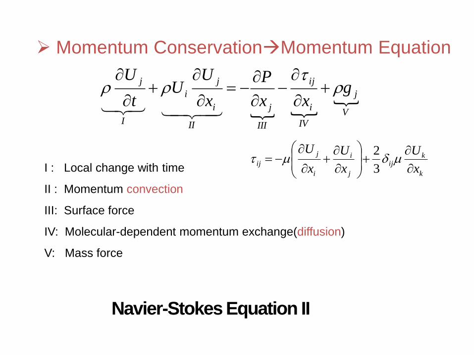
Navier-Stokes Equation II
Momentum ConservationMomentum Equation
V
j
IV
i
ij
III
j
II
i
j
i
I
jg
xx
P
x
UU
t
U
k
kij
j
i
i
j
ijx
U
x
U
x
U
3
2
I : Local change with time
II : Momentum convection
III: Surface force
IV: Molecular-dependent momentum exchange(diffusion)
V: Mass force

Navier-Stokes Equation III
Momentum Equation for Incompressible Fluid
j
i
j
ji
j
i
jg
x
U
x
P
x
UU
t
U
2
2
k
k
i
ij
j
i
i
j
ii
ij
x
U
xx
U
x
U
xx
3
2
0
i
i
x
U
2
2
2
2
i
j
i
i
ji
j
i
ij
x
U
x
U
xx
U
x

Navier-Stokes Equation IV
Energy ConservationEnergy Equation
V
i
j
ij
IV
i
III
i
i
II
i
i
I
x
U
x
T
x
UP
x
TUc
t
Tc
2
2
I : Local energy change with time
II: Convective term
III: Pressure work
IV: Heat flux(diffusion)
V: Irreversible transfer of mechanical energy into heat

Discretization
Discretization Methods Finite Difference
Straightforward to apply, simple, sturctured grids
Finite Element
Any geometries
Finite Volume
Conservation, any geometries
Analytical Equations Discretized Equations
Discretization

Finite Volume I
General Form of Navier-Stokes Equation
q
xU
xt i
i
i
TU j ,,1
S
i
V i
dSndVx
Integrate over the
Control Volume(CV)
Local change with time Flux Source
VS
i
i
i
V
dVqdSnx
UdVt
Integral Form of Navier-Stokes Equation
Local change
with time in CV
Flux Over
the CV Surface
Source in CV

Finite Volume II
Conservation of Finite Volume Method
VS
i
i
i
V
dVqdSnx
UdVt
A B
A B

Finite Volume III
;VdVm p
Vi
Approximation of Volume Integrals PU
eU
EU
Interpolation
0)( if
0)( if
eE
eP
e
nUU
nUUU
Upwind
Central
PE
PeeePeEe
xx
xxUUU
)1(
wesnkSPdSPdVP k
k
kSV ii
,,,
Approximation of Surface Integrals ( Midpoint Rule)
VudVumu PP
V
ii
i

BITS Pilani, Dubai Campus
The Navier-Stokes equations are the fundamental partial
differentials equations that describe the flow of incompressible
fluids.
Two of the alternative forms of equations of motion, using
the Eulerian description, were given as Equation (1) and
Equation (2) respectively:
jjiijji
i fqqt
q,,
)(
.1
,, jjiijij
ii fqqt
q
dt
dq
(1)
(2)
DERIVATION OF NAVIER-STOKES-DUHEM EQUATION

BITS Pilani, Dubai Campus
If we assume that the fluid is isotropic ,
homogeneous , and Newtonian, then :
.~2)
~( ijijkkij p (3)
DERIVATION (Cont’d)
Substituting Equ(3) into Equ(2), and utilizing the Eulerian
relationship for linear stress tensor we get :
,,,,
~~~1jjijijii
i qqpfdt
dq
(4)
( for compressible fluids )

BITS Pilani, Dubai Campus
For incompressible fluid flow the Navier-Stokes-
Duhem equation is:
jjiiii qpf
dt
dq,,
~1
DERIVATION (Cont’d)
If the fluid medium is a monatomic ideal gas, then :
~
3
2~

BITS Pilani, Dubai Campus
Navier stokes equation for compressible flow of
monatomic ideal gas is :
,,,,
~~
3
11jjijijii
i qqpfdt
dq
DERIVATION (Cont’d)

BITS Pilani, Dubai Campus
EXAMPLE PROBLEM
Neglecting the gravity field, describe the steady two- dimensional
flow of an isotropic , homogeneous,
Newtonian fluid due to a constant pressure gradient between two
infinite, flat, parallel, plates. State the necessary assumptions.
Assume that the fluid has a uniform density.

BITS Pilani, Dubai Campus
The Navier – stokes equations for incompressible flow is:
jjiiijiji qpfqq
dt
dq,,,
~1
Since the flow is steady and the body forces are
neglected, the Navier-stokes equation becomes:
jjiijij qpqq ,,,
~1
SOLUTION (Cont’d)

BITS Pilani, Dubai Campus
The no slip boundary conditions for viscous flow are:
0iq at ay 2
Using the boundary conditions ( q2= 0 at y2=+/- a )
Thus, the first Navier-stokes equations becomes
1
2
2
1
2
dy
dp
dy
qd
SOLUTION (Cont’d)

BITS Pilani, Dubai Campus
Integrating twice, we obtain
22
2
1
12
1ay
dy
dpq
The results, assumptions and boundary conditions of this
problem in terms of, mathematical symbols are as follows:
Constant 0if
0
t
0
3
y
22
2
1
12
1ay
dy
dpq
SOLUTION (Cont’d)

BITS Pilani, Dubai Campus
HOMEWORK PROBLEM
• Using the Navier-Stokes equations investigate the flow (qi) between
two stationary, infinite, parallel plates a distance h apart. Assuming
that you have laminar flow of a constant-density, Newtonian fluid
and the pressure gradient is constant (partial derivative of P with
respect to 1).

BITS Pilani, Dubai Campus
Types of Errors and Problems
Types of Errors:
Modeling Error.
Discretization Error.
Convergence Error.
Reasons due to which Errors occur:
Stability.
Consistency.
Conservedness and Boundedness.

BITS Pilani, Dubai Campus
Applications of CFD
1. Industrial Applications:
CFD is used in wide variety of disciplines and industries,
including aerospace, automotive, power generation, chemical
manufacturing, polymer processing, petroleum exploration,
pulp and paper operation, medical research, meteorology, and
astrophysics.
Example: Analysis of Airplane
CFD allows one to simulate the reactor
without making any assumptions about the
macroscopic flow pattern and thus to
design the vessel properly the first time.

BITS Pilani, Dubai Campus
Application (Contd..)
2. Two Dimensional Transfer Chute Analyses Using a
Continuum Method:
Fluent is used in chute designing tasks like predicting flow shape,
stream velocity, wear index and location of flow recirculation
zones.
3. Bio-Medical Engineering:
The following figure shows pressure
contours and a cutaway view that
reveals velocity vectors in a blood
pump that assumes the role of heart
in open-heart surgery.
Pressure Contours in Blood Pump

BITS Pilani, Dubai Campus
Application (Contd..)
4. Blast Interaction with a Generic Ship Hull
Results in a cut plane for the interaction of an
explosion with a generic ship hull: (a) Surface
at 20msec (b) Pressure at 20msec (c)
Surface at 50msec and (d) Pressure at
50msec
The figure shows the
interaction of an explosion
with a generic ship hull.
The structure was modeled
with quadrilateral shell
elements and the fluid as a
mixture of high explosives
and air. The structural
elements were assumed to
fail once the average strain
in an element exceeded 60
percent

BITS Pilani, Dubai Campus
Application (Contd..)
5. Automotive Applications:
Streamlines in a vehicle without (left) and with rear center and B-pillar ventilation (right)
In above figure, influence of the rear center and B-pillar ventilation on the
rear passenger comfort is assessed. The streamlines marking the rear
center and B-pillar ventilation jets are colored in red. With the rear center
and B-pillar ventilation, the rear passengers are passed by more cool air. In
the system without rear center and B-pillar ventilation, the upper part of the
body, in particular chest and belly is too warm.

BITS Pilani, Dubai Campus
The following are the details of conducting practicals
Five experiments are to be conducted in the CAD lab using ANSYS fluent software
1. Laminar flow through a circular pipe with constant radius
2. Turbulent flow though a circular pipe with constant radius
3. Compressible flow through a CD Nozzle
4. Steady flow over a rotating cylinder
5. Unsteady flow over rotating cylinder.
Four experiential are to be conducted using
Vapor Refrigeration test rig,
Wind tunnel and
Smoke analyzer.