cfd based simulation of hydrogen release through
TRANSCRIPT

CFD Based Simulation of Hydrogen Release through Elliptical Orifices
Nasim Shishehgaran and Marius Paraschivoiu
Concordia University
The 5th International Conference on Hydrogen Safety (ICHS)
Brussels, Belgium
September 9-11, 2013

- 2 -
Research Goal� Numerically investigate the effect of orifice geometry on the behavior and
development of hydrogen jet escaping from a high pressure reservoir.
Objectives
� Fixed elliptical and circular orifices with varying aspect ratios and sizes andunder different storage pressures.
� Expanding circular holes with uniform radial growth rates effective before therelease of hydrogen (t=0)
� Expanding circular holes with uniform radial growth rates effective after therelease of hydrogen
� Deformation of circular holes to elliptic openings
Governing Equations |Introduction | Numerical Method | Results |
Objectives |
Simulation Model | Contributions

- 3 -
Euler Equations: ���� � �. � � �
� �
�� �
, � �
�� � ���� � ��� � ��� � ����� � ��
� � � �� ��
�� � ���� � ���
�� � ��� � ��� � ��
�� � ��� � ��
� � ��� � ���� � ���
� � �� � �� � ��� � �
Governing Equations |Introduction | Numerical Method | Results |
Transport (Advection) Equation: ���� �
����� � ����� � ����� � ���
�� � ���� � ����� �
Abel Nobel Real Gas Law: � � �� � �������� , � � . !!"�# $%⁄
• '=0 a cell full of hydrogen
• 0<'<1 discontinuity (hydrogen-air interface)
• '=1 a cell full of air
Simulation Model | Contributions

- 4 -
� The system of Euler Equations is discretized using an implicit finite volume discretization scheme.
()*)+,- � *)+
∆/ � 0 122345+,-. 6345 ∆734589:;345
= 0
()∆/ =2
2+ 0 >122>* 345
+
. 6345 ∆734589:;345
?*)+,- = − 0 122345+ . 6345 ∆734589:;345
� Spatial Discretization (Convection Flux)� @ABorder Roe-MUSCL scheme
� Temporal Discretization � �C� order Implicit Scheme
� Linear Solver � Iterative Method : GMRES
Discretization
Moving Mesh
A�D� , ∆E�D� and ()are time-dependent.
Governing Equations |Introduction | Numerical Method | Results |
Discretization | Limiter |
Simulation Model | Contributions

- 5 -
Computational Domain
� 3D unstructured tetrahedral mesh
Grid Resolution
Grid Level Number of Nodes
Number of Tetrahedrons
Fine F3 G �H F17.5 G �HMedium F2 G �H F12 G �HCoarse F1 G �H F H G �H
the discretized domain with decomposed zones using METIS (partially shown)
2D slice of the computational domain
Pressurized reservoir
Low-pressure environment
Release tube
Governing Equations |Introduction | Numerical Method | Results |
3D Tetrahedral Mesh | Types of Orifices |
� METIS software package is used to distribute thefinite element/volume mesh to the processors andpartition the domain for parallel computing.
Simulation Model |
Initial & Boundary Conditions |
Contributions

- 6 -
� The parameter under consideration for comparable fixed circular and ellipticalorifices is the same exit area.
� Expanding orifices with initial diameters of Di=1 mm and Di=2 mm.
� The length of release tube is equal in all cases = 2mm.
Area=0.8 (mm2)Orifice Type
Major Axis,a (mm)
Minor Axis,b (mm)
Aspect Ratio,
a/bCircular 1 1 1
Elliptical 1 2 0.5 4Elliptical 2 2.45 0.41 6
Area=3.14 (mm2)Circular 2 2 1
Elliptical 1 4 1 4Elliptical 2 5 0.82 6
Area=19.63 (mm2)Circular 5 5 1
Elliptical 1 10 2.5 4Elliptical 2 12.25 2.04 6
Fixed (Circular & Elliptical) and Enlarging Orifices
The cross sectional surfaces of the varying ARs of the orifices with the equal exit area (A=19.63 mm2 )
Governing Equations |Introduction | Numerical Method | Results |
3D Tetrahedral Mesh | Types of Orifices |
AR=6AR=4
AR=1
Simulation Model |
Initial & Boundary Conditions |
Contributions
- 7 -
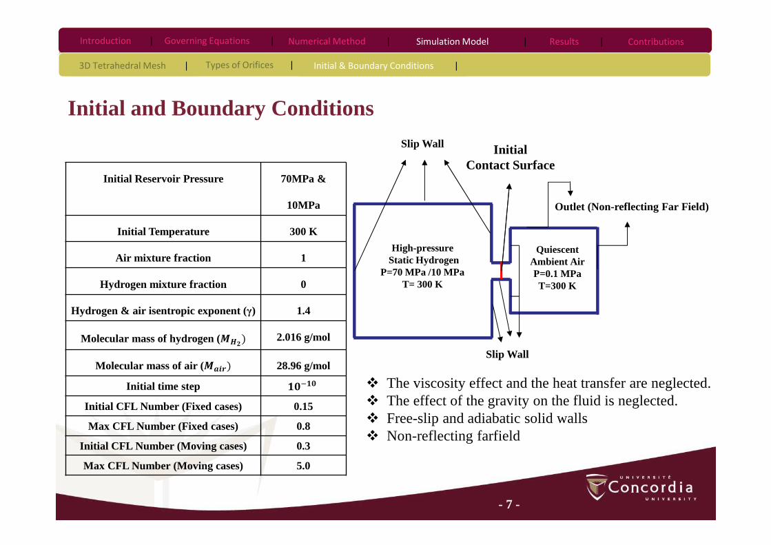
Initial and Boundary Conditions
Governing Equations |Introduction | Numerical Method | Results |
Initial Reservoir Pressure 70MPa &
10MPa
Initial Temperature 300 K
Air mixture fraction 1
Hydrogen mixture fraction 0
Hydrogen & air isentropic exponent (γ) 1.4
Molecular mass of hydrogen (IJ@� 2.016 g/mol
Molecular mass of air (IK�L� 28.96 g/mol
Initial time step ���Initial CFL Number (Fixed cases) 0.15
Max CFL Number (Fixed cases) 0.8
Initial CFL Number (Moving cases) 0.3
Max CFL Number (Moving cases) 5.0
Slip Wall
Outlet (Non-reflecting Far Field)
Slip Wall
High-pressureStatic Hydrogen
P=70 MPa /10 MPaT= 300 K
Quiescent Ambient AirP=0.1 MPaT=300 K
Initial Contact Surface
� The viscosity effect and the heat transfer are neglected.� The effect of the gravity on the fluid is neglected.� Free-slip and adiabatic solid walls� Non-reflecting farfield
Simulation Model |
3D Tetrahedral Mesh | Types of Orifices | Initial & Boundary Conditions |
Contributions
- 8 -
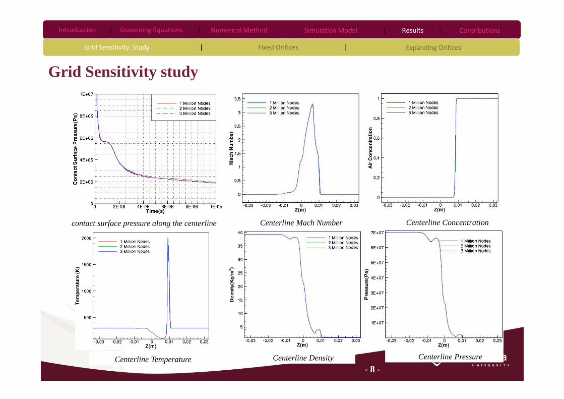
Grid Sensitivity study
Governing Equations |Introduction | Numerical Method | Results |
Grid Sensitivity Study | Fixed Orifices | Expanding Orifices
Centerline Mach Number Centerline Concentration
Centerline Density Centerline Temperature Centerline Pressure
contact surface pressure along the centerline
Simulation Model | Contributions

- 9 -
Evaluation of the contact surface location and the release time( Fixed Circular & Elliptical Orifices )
Release time= 0.6 µs Release time= 1 µs
Storage Pressure =70 MPa Storage Pressure =10 MPa
Governing Equations |Introduction | Numerical Method | Results |
Grid Sensitivity Study | Fixed Orifices | Expanding Orifices
Simulation Model | Contributions
D= 1mm D= 2mm D= 5mm

- 10 -
a) Area= 0.8 MM @ b) Area= 3.14 MM @ c) Area= 19.63 MM @
Contact Surface Pressure (Fixed Orifices), P=70 MPa
The same cross sectional area
Higher Aspect Ratio
More pronounced expansion
The same aspect ratio
Smaller release hole
More pronounced expansion
Rapid depressurization
Governing Equations |Introduction | Numerical Method | Results |
Grid Sensitivity Study | Fixed Orifices | Expanding Orifices
Simulation Model | Contributions

- 11 -
a) Area= 0.8 MM @ b) Area= 3.14 MM @ c) Area= 19.63 MM @
Contact Surface Pressure (Fixed Orifices), P=10 MPa
The same cross sectional area
Lower the storage pressure
Less pronounced expansion
Governing Equations |Introduction | Numerical Method | Results |
Grid Sensitivity Study | Fixed Orifices | Expanding Orifices
Simulation Model | Contributions

- 12 -
Centerline Temperature (Fixed Orifices, P=70 MPa)a) Circular Orifice, AR=1 b) Elliptical Orifice, AR=4 c) Elliptical Orifice, AR=6
Area= 0.8 MM @
Area= 3.14 MM @
Area= 19.63 MM @
Governing Equations |Introduction | Numerical Method | Results |
Grid Sensitivity Study | Fixed Orifices | Expanding Orifices
Simulation Model | Contributions

- 13 -
Centerline Temperature (Fixed Orifices, P=10 MPa)a) Circular Orifice, AR=1 b) Elliptical Orifice, AR=4 c) Elliptical Orifice, AR=6
Area= 0.8 MM @
Area= 3.14 MM @
Area= 19.63 MM @
Governing Equations |Introduction | Numerical Method | Results |
Grid Sensitivity Study | Fixed Orifices | Expanding Orifices
Simulation Model | Contributions

- 14 -
Centerline Temperature (Fixed Orifices, P=10 MPa)a) Centerline Mach Number b) Centerline Density c) Centerline Pressure
Area= 0.8 MM @
Area= 3.14 MM @
Area= 19.63 MM @
Governing Equations |Introduction | Numerical Method | Results |
Grid Sensitivity Study | Fixed Orifices | Expanding Orifices
Simulation Model | Contributions

- 15 -
After 10 µs of hydrogen release into air from the
circular and elliptical orifices (Area=3.14 mm2)
(Minor Axis)
Mach Number Concentration
(Major Axis) (Minor Axis) (Major Axis)
Temperature
(Minor Axis) (Major Axis)
Elli
ptic
al o
rifi
ce (
AR
=4)
Cir
cula
r or
ific
e (A
R=1
)
Governing Equations |Introduction | Numerical Method | Results |
Grid Sensitivity Study | Fixed Orifices | Expanding Orifices
Simulation Model | Contributions

- 16 -
t=0 (Initial Diameter)
t=5 µs
t=10 µs
Two dimensional views of the expanding release hole (Di=2mm)
Release time= 0.6 µs
Release time= 1 µs
Circular Expanding Orifices effective at t=0
Governing Equations |Introduction | Numerical Method | Results |
Grid Sensitivity Study | Fixed Orifices | Expanding Orifices
Simulation Model |
� Growth RateV= 0.2 mm/µs
P=10 MPa
P=70 MPa
Contributions
- 17 -
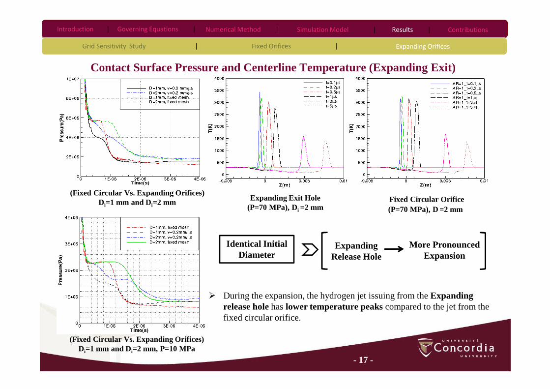
Contact Surface Pressure and Centerline Temperature (Expanding Exit)
(Fixed Circular Vs. Expanding Orifices)Di=1 mm and Di=2 mm, P=10 MPa
Expanding Exit Hole (P=70 MPa), Di =2 mm
Fixed Circular Orifice(P=70 MPa), D =2 mm
(Fixed Circular Vs. Expanding Orifices)Di=1 mm and Di=2 mm
Identical Initial Diameter
Expanding Release Hole
More Pronounced Expansion
� During the expansion, the hydrogen jet issuing from the Expanding release hole has lower temperature peaks compared to the jet from the fixed circular orifice.
Governing Equations |Introduction | Numerical Method | Results |
Grid Sensitivity Study | Fixed Orifices | Expanding Orifices
Simulation Model | Contributions
- 18 -
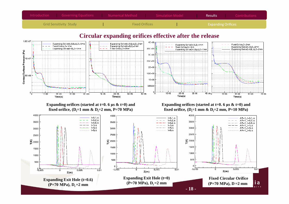
Circular expanding orifices effective after the release
Expanding orifices (started at t=0. 6 µs & t=0) and fixed orifice, (Di=1 mm & Di=2 mm, P=70 MPa)
Expanding orifices (started at t=0. 6 µs & t=0) and fixed orifice, (Di=1 mm & Di=2 mm, P=10 MPa)
Expanding Exit Hole (t=0.6)(P=70 MPa), Di =2 mm
Expanding Exit Hole (t=0) (P=70 MPa), Di =2 mm
Fixed Circular Orifice(P=70 MPa), D =2 mm
Governing Equations |Introduction | Numerical Method | Results |
Grid Sensitivity Study | Fixed Orifices | Expanding Orifices
Simulation Model | Contributions

- 19 -
Deformation of a small circular hole to an elliptical opening
Cross sectional areas, Di=2mm, v=0.2mm/µs Side views, Di=2mm, v=0.2mm/µs
Release time= 0.6 µs
Release time= 1 µs
P=70 MPa
P=10 MPa
� Stretching rate = 0.2 mm/µs
Governing Equations |Introduction | Numerical Method | Results |
Grid Sensitivity Study | Fixed Orifices | Expanding Orifices
Simulation Model | Contributions
- 20 -
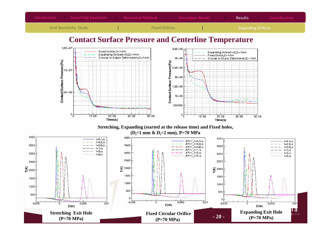
Contact Surface Pressure and Centerline Temperature
Stretching, Expanding (started at the release time) and Fixed holes, (Di=1 mm & Di=2 mm), P=70 MPa
Stretching Exit Hole (P=70 MPa)
Fixed Circular Orifice(P=70 MPa)
Expanding Exit Hole (P=70 MPa)
Governing Equations |Introduction | Numerical Method | Results |
Grid Sensitivity Study | Fixed Orifices | Expanding Orifices
Simulation Model | Contributions

- 21 -
Contributions
� The effects of different geometries and configurations of the exit hole including fixed elliptical,fixed circular and expanding orifices on the dispersion of hydrogen were studied using a 3Dparallel in-house code.
� The effects of the storage pressure and the size of the orifice on the dispersion and developmentof the hydrogen jet are dominant than the effect of the orifice shape.
� The possibility of auto-ignition may be affected by applying expanding orifices.
Governing Equations |Introduction | Numerical Method | Results | ContributionsSimulation Model |

- 22 -
Thank You