ces5^-*esearc library
TRANSCRIPT

J
CES5^-*ESEARC" LIBRARYn c TION
3 MH5b D35fib77 6
ORNL-NSIC-26
UC-80 — Reactor Technology
83
TESTING OF CONTAINMENT SYSTEMS USED WITH
LIGHT-WATER-COOLED POWER REACTORS
Frank C. Zapp
OAK RIDGE NATIONAL LABORATORY
CENTRAL RESEARCH LIBRARY
DOCUMENT COLLECTION
LIBRARY LOAN COPYDO NOT TRANSFER TO ANOTHER PERSON
If you wish someone else to see thisdocument, send in name with documentand the library will arrange a loan.
NUCLEAR SAFETY INFORMATION CENTER NSIC
Printed in the United States of America. Available from Clearinghouse for FederalScientific and Technical Information, National Bureau of Standards,
U.S. Department of Commerce, Springfield, Virginia 22151
Price: Printed Copy $3.00; Microfiche $0.65
LEGAL NOTICE
This report was prepared as an account of Government sponsored work. Neither the United States,nor the Commission, nor any person acting on behalf of the Commission:
A. Makes any warranty or representation, expressed or implied, with respect to the accuracy,completeness, or usefulness of the information contained in this report, or that the use of
any information, apparatus, method, or process disclosed in this report may not infringeprivately owned rights; or
B. Assumes any liabilities with respect to the use of, or for damages resulting from the use ofany information, apparatus, method, or process disclosed in this report.
As used in the above, "person acting on behalf of the Commission" includes any employee orcontractor of the Commission, or employee of such controctor, to the extent that such employeeor contractor of the Commission, or employee of such contractor prepares, disseminates, or
provides access to, any information pursuant to his employment or contract with the Commission,or his employment with such contractor.
«

Contract No. W-74-05-eng-26
Nuclear Safety Information Center
TESTING OF CONTAINMENT SYSTEMS USED WITIi
LIGHT-WATER-COOLED POWER REACTORS
Frank C. Zapp
AUGUST 1968
ORNL-NSIC-26
MARTIN MARIETTA ENERGY SYSTEMS LIBRARIES
3 M45b D3Sflb77 A
OAK RIDGE NATIONAL LABORATORY
Oak Ridge, Tennesseeoperated "by
UNION CARBIDE CORPORATION
for the
U.S. ATOMIC ENERGY COMMISSION


Ill
FOREWORD
The recent surge in the building of large nuclear power plants, par
ticularly with the projected desirability of using urban sites for such
installations, has focused attention on many aspects of the AEC's respon
sibilities for licensing reactors and insuring the public safety. Since
the industry is "young," meaningful, long-term operating experience is
sparse and the definition of the possible accident spectrum, as well as
a set of firm design requirements, is subject to a largely analytical
approach that necessarily involves conservative judgments. As plant de
signs become standardized and operating experience on the newer large re
actors is gained, the inevitable process of refinement and of acquiring
confidence in the operation of the plants will occur. This relatively
slow evolutionary approach to acquiring firm design standards and criteria
is not felt to be conducive to achieving the great national benefits of
atomic energy within a reasonable time, in terms of the conservation of
resources, combating air pollution, and the multitude of gains resulting
from low-cost electricity.
As part of the effort to improve on this approach, the Regulatory
Review (Mitchell) Panel recommended the formation by the AEC of a Steer
ing Committee on Reactor Safety Research to coordinate the needs of the
Regulatory Program with the direction of the safety research and develop
ment programs. This committee, in turn, recommended that several studies
be undertaken to provide guidance for the research and development pro
jects, and this was, in turn, implemented by the AEC Division of Reactor
Development and Technology into the series of discussion reports herein
described. It was intended that these reports provide a comprehensive as
sessment of the present status of specific aspects of nuclear safety and,
by identifying accepted technology and the technology needing further
experimental verification, that they enhance the understanding and con
fidence in this new industry.
Accordingly a number of the safety aspects of large light-water power
reactors were selected by the AEC* as subjects for detailed study to
^Letter from Milton Shaw (Director, AEC Division of Reactor Development and Technology) to ORNL, March 28, 1966.

IV
ascertain whether gaps in knowledge exist and where a research and develop
ment program could be of benefit. The subjects selected cover many of
the areas for which inadequate factual bases exist and in which research
that duplicates expected conditions is very difficult to perform. In
general the subjects are in areas considered critical in the safety
analysis of power reactor installations. Eight subjects were identified
and a state-of-technology type of discussion report was prepared on each.
The reports, which are directed primarily toward a technical-management
audience, generally compare existing or planned plant applications with
what is capable of being done at this time. Such comparisons have helped
to identify inadequacies in assumptions, available data, or general basic
knowledge so that, together with the opinions of experts in a particular
field, areas of meaningful research and development have been identified.
This report is one of the series of eight companion reports listed
below:
Title
Missile Generation and Protection in
Light-Water-Cooled Power Reactor
Plants
Potential Metal-Water Reactions in
Light-Water-Cooled Power Reactors
Emergency Core-Cooling Systems forLight-Water-Cooled Power Reactors
Air Cleaning as an Engineered SafetyFeature in Light-Water-Cooled Power
Reactors
Testing of Containment Systems Usedwith Light-Water-Cooled Power Reac
tors
Review of Methods of Mitigating Spreadof Radioactivity from a Failed Containment System
Earthquakes and Nuclear Power PlantDesign
Protection Instrumentation Systems inLight-Water-Cooled Power ReactorPlants
Author
R. C. Gwaltney
H. A. McLain
C. G. Lawson
G. W. Keilholtz,C. E. Guthrie, andG. C. Battle, Jr.
F. C. Zapp
R. C. Robertson
T. F. Lomenick and
C. G. Bell
C. S. Walker
ORNL-NSIC
No.
22
23
24
25
26
27
28
29
V
Although not specifically one of this series, a related discussion
report on reactor pressure vessels, ORNL-NSIC-21, edited by G. D. Whitman,
G. C. Robinson, and A. W. Savolainen, has also been prepared at ORNL.
The general approach in the preparation of these reports was to select
a primary author-investigator knowledgeable in the subject area and to
establish committees of experts to review the work at several stages during
its preparation. Review groups were formed both from within ORNL and
outside. The external review committee members were drawn principally
from other national laboratories, universities, and private research in
stitutes — in all, 52 individuals participated and are identified in the
reports. In some cases, part of the material used was developed and/or
written by a subcontractor, who is similarly identified. In all cases,
correspondence and/or visits were made to many sources of information,
particularly to reactor operators, suppliers, architect-engineers, and
public utilities, as well as to the appropriate national laboratories.
This wide use of acknowledged experts was made in an attempt, to include
their opinions and knowledge toward the ultimate goal of achieving, through
intensive research and development programs, well-defined design criteria
to insure the public health and safety and to maintain a viable nuclear
power industry. However, in all Instances the authors have expressed con
clusions and recommendo.tions that reflect their own judgment and not that
of any particular group, such as the AEC, reactor designers, or utilities.
In most subject areas more information was developed than it has been
possible to include in the body of the reports prepared in this series.
In some instances, such information has been included in the appendices
and in other instances this information will be included in more techni
cally oriented reports to be published in the near future. In addition,
it is expected that additional discussion reports will be written on some
of the many other safety aspects of large water-cooled reactors, as well
as other types of reactors as they come into wider usage.
J. W. Michel
Coordinator, Discussion PapersOak Ridge National Laboratory
Wm. B. Cottrell
Director, Nuclear Safety ProgramOak Ridge National Laboratory


VI1
PREFACE
The Nuclear Safety Information Center was established in March 1963
at the Oak Ridge National Laboratory under the sponsorship of the U.S.
Atomic Energy Commission to serve as a focal point for the collection,
storage, evaluation, and dissemination of nuclear safety information.
A system of keywords is used to index the information cataloged by the
Center. The title, author, installation, abstract, and keywords for each
document reviewed is recorded on magnetic tape at the central computer
facility in Oak Ridge. The references are cataloged according to the
following categories:
1. General Safety Criteria2. Siting of Nuclear Facilities3. Transportation and Handling of Radioactive Materials4. Aerospace Safety5. Accident Analysis6. Reactor Transients, Kinetics, and Stability7. Fission Product Release, Transport, and Removal8. Sources of Energy Release Under Accident Conditions9. Nuclear Instrumentation, Control, and Safety Systems
10. Electrical Power Systems
11. Containment of Nuclear Facilities
12. Plant Safety Features13. Radiochemical Plant Safety14. Radionuclide Release and Movement in the Environment
15. Environmental Surveys, Monitoring and Radiation Exposure of Man16. Meteorological Considerations
17. Operational Safety and Experience18. Safety Analysis and Design Reports19. Bibliographies
Computer programs have been developed that enable NSIC to (l) pro
duce a quarterly indexed bibliography of its accessions (issued with
ORNL-NSIC report numbers); (2) operate a routine program of Selective
Dissemination of Information (SDl) to individuals according to their par
ticular profile of interest; and (3) make retrospective searches of the
references on the tapes.
Other services of the Center include principally (l) preparation of
state-of-the-art reports (issued with ORNL-NSIC report numbers); (2) co
operation in the preparation of the bimonthly technical progress review,
Nuclear Safety; (3) answering technical inquiries as time is available,
and (4) providing counsel and guidance on nuclear safety problems.

Vlll
Services of the NSIC are available without charge to government
agencies, research and educational institutions, and the nuclear indus
try. Under no circumstances do these services include furnishing copies
of any documents (except NSIC reports), although all documents may be
examined at the Center by qualified personnel. Inquiries concerning the
capabilities and operation of the Center may be addressed to
J. R. Buchanan, Assistant DirectorNuclear Safety Information CenterOak Ridge National Laboratory
Post Office Box Y
Oak Ridge, Tennessee 37830Phone 615-483-8611, Ext. 3-7253FTS 615-483-7253
IX
ACKNOWLEDGMENTS
Appendix A contains a listing of persons who have in some way con
tributed information and/or assistance in preparing this report. Their
helpfulness is gratefully acknowledged.
Special thanks are due the external Review Committee members,
R. 0. Brittan — Argonne National Laboratory, G. J. Rogers — Pacific
Northwest Laboratories, and R. N. Bergstrom — Sargent & Lundy; the in
ternal ORNL Review Committee members, W. R. Gall, F. T. Binford, and
C. G. Robinson; N. K. Sowards - Phillips Petroleum Company; R. R. Maccary
AEC Division of Reactor Standards; members of the ORNL Reactor Division,
W. B. Cottrell, J. W. Michel, S. E. Beall, and J. R. Buchanan and the
Staff of the Nuclear Safety Information Center.
R. 0. Brittan, G. J. Rogers, G. C. Robinson, R. R. Maccary, J. A.
Hinds, and J. W. Michel have been especially helpful during the prepa
ration of this report.


XI
CONTENTS
ABSTRACT
SUMMARY 1
1. INTRODUCTION 5
1.1 Purpose and Scope 5
1.2 Containment Systems 6
1.2.1 Pressure Containment 7
1.2.2 Pressure-Suppression Containment 9
1.2.3 Conventional Buildings as ContainmentStructures 11
1.3 Leakage Rates 11
1.4 Containment Accident Conditions 14
1.5 Purpose of Containment System Testing 19
1.5.1 Strength Testing 21
1.5.2 Integrated Leakage-Rate Testing 22
1.5.3 Leakage Surveillance Testing 22
1.5.4 Engineered Safety Feature Testing 23
2. APPLICABLE CODES, STANDARDS, AND REGULATORY REQUIREMENTS ... 24
2.1 Codes, Standards, and Guides 24
2.2 AEC Technical Safety Guide 30
2.3 Regula,tory Provisions 37
2.3.1 Regulatory Review Panel 37
2.3.2 Reactor Design Criteria, 39
2.3.3 Atomic Energy Commission Regulatory Branch 40
2.3.4 Basic Documents 41
3. TESTING TECHNIQUES, EXPERIENCE, AND CURRENT PRACTICE 43
3.1 Strength Testing 45
3.1.1 Steel Containment Vessels 45
3.1.2 Reinforced-Concrete Containment Structures 50
3.1.3 Prestressed-Concrete Containment Structures .... 52
3.1.4 Composite Structures 56
Page
xv

Xll
3.1.5 Conventional Buildings 57
3.1.6 Multiple-Barrier Containment Structures 57
3.2 Integrated Leakage-Rate Testing 57
3.2.1 Methods of Performing Integrated Leakage-Rate Tests 58
3.2.2 Calculational Methods of Analysis 65
3.2.3 Bare-Vessel Leakage-Rate Tests 78
3.2.4 Preoperational Tests 79
3.2.5 Periodic Retesting 79
3.2.6 Continuous Integrated Leakage-Rate Testing 83
3.2.7 Conventional Building Tests 85
3.2.8 Multiple-Barrier Containment Tests 86
3.3 Leakage Surveillance Testing 88
3.3.1 Local Leak Testing 88
3.3.2 Penetration Testing 90
3.3.3 Weld-Sean Testing 97
3.3.4 Isolation-Valve Testing 98
3.3.5 Testing of Isolation Valves In Main SteamLines 101
3.3.6 Seal Water Systems for Isolation Valves 102
3.4 Industrial Meeting on Containment Testing 103
3.5 Review of Containment Leakage-Rate Test Reportsand Guidelines for Leakage-Rate Testing 107
3.6 Testing of Engineered Safety Features Associatedwith Containment Systems 112
3.6.1 Testing of Air-Recirculation and -CoolingSystems 113
3.6.2 Testing of Containment Spray Systems 115
3.6.3 Other Heat-Removal Systems 116
CONTAINMENT SYSTEMS TESTING RESEARCH 119
4.1 Containment System Experiment 121
4.2 Loss-of-Fluid Test 124
4.3 CVTR In-Plant Testing Program 124
4.4 Summary 127

Xlll
5. CONCLUSIONS 129
5.1 Available Information 129
5.2 Changing Technology 129
5.3 Effects of Related Systems 130
5.4 Reliable Safety Features 130
5 .5 Test Reports 130
5.6 Testing Problems 131
5.7 Isolation Valves 131
5.8 Monitoring Systems 131
5.9 Leakage-Rate Correlation 132
5.10 Testing Methods 132
5.11 Concrete Containment 133
5.12 Selection of Testing Method 133
5.13 Preoperational Tests 134
5.14 Proposed ANS Standard 134
5.15 AEC Technical Safety Guide 135
5.16 NASA Report on Leakage-Rate Testing 135
5.17 Safety Analysis Reports and TechnicalSpecifications 135
6. RECOMMENDATIONS 137
6.1 Codes, Standards, and Guides 137
6.2 Siting Criteria 137
6.3 ANS Standard 138
6.4 Testing Reports and Guidelines 138
6.5 Technical Specifications 139
6.6 AEC Technical Safety Guide 140
6.7 Continuous Monitoring Systems 140
6.8 Continuous Monitoring Research 140
6.9 Testing Techniques, Experience, and Practice 140
6.10 Containment Systems Testing Research 142
6.11 Standard Terminology 144
REFERENCES 145
APPENDIX A. REVIEW COMMITTEES AND INFORMATION SOURCES 155
APPENDIX B. TECHNICAL SAFETY GUIDE 157

XIV
APPENDIX C. ANS 7.60 - PROPOSED STANDARD FOR LEAKAGE-RATETESTING OF CONTAINMENT STRUCTURES 175
APPENDIX D. PERTINENT AEC GENERAL DESIGN CRITERIA - 1967 203
APPENDIX E. REVIEW OF NASA REPORT COMPARING ABSOLUTE ANDREFERENCE-VESSEL METHODS OF LEAKAGE-RATE
TESTING 207
APPENDIX F. COMPARISON OF METHODS OF DETERMINING CONTAINMENT LEAKAGE RATES AND MAXIMUM POSSIBLE
ERROR ANALYSES 217
APPENDIX G. CVTR IN-PIANT TEST PROGRAM 239
APPENDIX H. CONTAINMENT SYSTEMS EXPERIMENT 249
APPENDIX I. LOSS-OF-FLUID TEST 253

XV
ABSTRACT
An evaluation of the testing of containment systems used with light-
water-cooled nuclear power reactors was made through discussions with
members of the nuclear power industry and studies of published litera
ture, reports of leakage-rate tests, technical specifications, and in
formation available in preliminary and final safety analysis reports and
their supplements. Conclusions are presented relative to leakage-rate
test results, continuous leakage-rate monitoring, and developments that
may affect future testing requirements. Also, recommendations are made
relative to proposed codes, standards, and guides; isolation-valve test
ing; containment air-cooling and spray systems testing; and containment
systems testing research programs.
The studies indicated that integrated leakage-rate test results are
not currently being reported in a manner that is conducive to comparisons
between plants or to an independent evaluation of the errors involved.
In most cases there is insufficient information presented in the leakage-
rate test reports to adequately support the degree of accuracy claimed
or to give confidence in the leakage result reported. The majority of
the errors are the result of inadequate precision of the test equipment
used, inadequate test equipment calibration, and (more significantly)
poorly designed sampling techniques. A major need appears to be that of
providing guidelines for correctly defining the leakage-rate tests so
that the accuracy and significance of the results can be predicted before
the test is run.
The technology of containment systems testing is relatively well de
veloped, but additional research and analysis is warranted to (l) improve
leakage-rate testing accuracy and reliability, (2) to correlate leakage
under test conditions with that expected under accident conditions, (3)
improve and develop continuously monitoring integrated-leakage and/or
leakage-rate surveillance systems, (4) investigate methods of continuously
monitoring all containment engineered safety features, and (5) provide
realistic and meaningful procedures for testing the capability and reli
ability of reactor containment engineered safety features under accident
conditions.


SUMMARY
This report on Containment Systems Testing is one of a. series prepared
by the Oak Ridge National Laboratory at the request of the USAEC's Divi
sion of Reactor Development and Technology as part of their continuing pro
gram to review the safety aspects of light-water power reactor technology
In order to determine where additional research and analysis would, be
useful. A substantial body of containment and associated systems design
and operating experience has been accumulated for existing power reactors,
and a comprehensive research program is being conducted, primarily in the
Containment Systems Experiment at the Pacific Northwest Laboratories of
the Battelle Memorial Institute. Containment technology is presently in
a state of transition to designs for which no experience exists (pre-
stressed concrete, new pressure-suppression devices, etc.) and the re
search programs will inevitably lag behind the changing technology.
An attempt is made in this report to relate the information gained
from the experience to date to the information researchers hope to gain
from test programs currently under way. This is done by discussing appli
cable codes, standards, and guides; testing techniques, experience, and
current practice; administrative considerations; and the containment re
search programs that involve some degree of containment systems testing
research. The discussion of testing techniques, experience, and current
practice includes consideration of containment system strength tests,
integrated leakage-rate tests, and leakage-surveillance tests, as well as
testing of related engineered safety features. The discussion of con
tainment systems testing research deals with the Containment Systems
Experiment, the Loss of Fluid Test Program, and the In-Plant Test Program
proposed for the Carolinas-Virginia Tube Reactor. On the basis of these
discussions it is concluded that the technology of containment systems
testing is relatively well developed but that additional research and
analysis are warranted to (l) improve leakage-rate testing accuracy and
confidence in test results, (2) to correlate leakage under test conditions
with that expected under accident conditions, and (3) to provide realistic
and meaningful procedures for testing the effectiveness and reliability

of reactor containment engineered safety features under postaccident con
ditions.
Testing requirements have not been developed for the new large
[800-1000 Mw(e)] nuclear plants because the preliminary safety analysis
reports require only statements of intent to satisfy AEC design criteria.
In most cases this type of information, including testing procedures, is
not available until the later stages of design and is therefore currently
being developed and reviewed. The CVTR In-Plant Test Program was recently
modified and realigned to emphasize testing of containment system response
to simulated design-basis-accident conditions.
It is concluded that leakage-rate test results are not currently
being reported in a manner conducive to comparisons between plants or to
an independent evaluation of the errors involved. In most cases there
is insufficient information presented in the leakage-rate test reports
to support the degree of accuracy claimed or to give confidence in the
leakage result reported. The majority of the errors are the result of
inadequate precision of the test equipment used, inadequate test equip
ment calibration, and (more significantly) poorly designed sampling tech
niques. A major need appears to be that of providing guidelines for cor
rectly defining the leakage-rate tests so that the required accuracy and
significance of the results can be predicted before the test is run.
Recommendations are made relative to specific ways in which the
current testing methods and research programs can be improved. Consider
ation should be given to providing additional government support of the
work being done to develop codes and standards consistent with today s
technology in order to decrease the time required to develop these im
portant documents. Consideration should be given to testing the heat
transfer capability and design performance of a typical air-cooling sys
tem in a simulated accident atmosphere. Design performance tests of a
typical containment spray system under accident atmospheric conditions
should also be conducted. Plans have been made by the PA&ET Branch of
the Phillips Petroleum Company to perform tests of this type in the Caro-
linas-Virginia Tube Reactor. Reactor plant design and construction con
tractors should test their actual containment air-cooling systems under
simulated accident conditions prior to installation in the reactor plant.

It is also recommended that the actual containment spray systems be
tested. This could be done early in the construction schedule prior to
the installation of equipment that could be damaged.
The subject of isolation-valve testing has been handled to date in
a rather haphazard manner compared with the way other aspects of contain
ment systems testing have been approached. It is considered that this
area requires additional technical and regulatory effort, and work should
be initiated to develop and standardize methods of performing isolation-
valve tests.
Periodic integrated leakage-rate tests at relatively high pressure
(usually 50^ of design basis accident pressure) are now used to verify
the allowable test leakage rates specified in technical specifications.
The test results verify to the AEC Compliance Division that the leakage
rate is within the prescribed limits only at the time of the test, and
there is no guarantee that within a week or month there may not be a ten
fold increase in leakage rate.
Continuous integrated leakage-rate testing at relatively low pressure
is an extremely valuable tool, since it increases the assurance of both
the reactor operator and the AEC that the health and safety of the public
are being protected on a continuous basis. A continuously monitoring
system of this type can be instrumented to immediately indicate any major
leaks and to disclose minor leaks in a relatively short period of time.
The level of containment leakage-rate integrity, however, will be related
to the accuracy of the technique used, and it will not be possible to
confirm that the containment system is meeting the technical specifica
tions If the leakage rate specified is below the threshold of detection
of the continuous monitoring system.
Research and development programs of both the AEC and industry should
investigate ways to (l) improve existing continuous leakage-monitoring
techniques to insure that containment integrity (to as great a degree
as possible) is being maintained at all times and (2) develop new tech
niques. If possible, continuous monitoring methods should be developed
to insure that all containment engineered safety features will function
reliably and effectively following a loss-of-coolant accident.

4
It appears that the Absolute Method of integrated-leakage-rate test
ing will be utilized for many future large power reactor containment sys
tems. The use of large metallic-lined concrete-encased structures with
their inherent stable temperature conditions is a major factor in the
selection of this method, as well as the simplicity of test preparation
and instrumentation, savings in time, and lower overall cost.
There is a need to standardize the terminology used in the safety
analysis reports, the technical specifications, and in the leakage-rate
test reports. It is recommended that the terminology used in AEC Techni
cal Safety Guide III, "Reactor Containment Leakage Testing and Surveillance
Requirements," be adopted throughout the industry and that the leakage
rates be reported in specific terms, as outlined in Section 3.5 of this
report.

1. INTRODUCTION
1.1 Purpose and Scope
The tests that are performed on pressurized- and boiling-water nu
clear power reactor containment systems to assure initial and continuing
integrity and operability of these systems are discussed in this report,
and an attempt is made to present a clear picture of the current state-
of the art of containment systems testing in order to identify those
areas where additional research and development are needed. The subject
is introduced by first defining containment systems and describing the
basis for establishing allowable leakage rates. The purpose of contain
ment systems testing and the codes, standards, and guides used in perform
ing such tests are then discussed.
Testing techniques, experience, and current practice are described.
The categories of tests include strength tests, integrated and local
leakage-rate tests, tests associated with equipment and devices that es
tablish containment boundaries, and tests of certain engineered safety
features. The administrative considerations associated with conducting
these tests are described briefly. The final, and very important, sec
tion of this report discusses the research and development work currently
being undertaken in the field of containment systems testing.
Because of the large amount of material already published on the con
tainment of nuclear reactors and the short time available to complete a
discussion report on the subject of containment testing, liberal use was
made of the information contained in available publications. The publi
cation "U.S. Reactor Containment Technology"1 for example, presents an
exhaustive study of this field and frequent references to sections in that
document are made. Discussions with members of the nuclear power industry,
including utilities, reactor manufacturers, the AEC, and architect-engi
neers and constructors regarding containment testing, as well as published
reports of tests and information available in preliminary and final safety
analysis reports and their supplements, were also considered. A basic
ground rule excluded the use of proprietary information.

Power plant owners and operators are primarily interested in pro
ducing as much power as possible and maintaining a high plant availability
factor; therefore they are interested in minimizing containment system
testing on a shutdown basis. Downtime costs can be as high as $50,000
per day for large power plants, and thus there is an incentive to reduce
the time required for containment testing and surveillance, consistent
with maintaining safe plant operation. Enthusiasm for further development
of in-service (during plant operation) testing can be expected from in
dustry, although downtime testing will also be required for correlation.
Some operating organization representatives feel that the subject of
leakage-rate testing has been overemphasized; although postaccident dose
rates to the environs are a function of (l) activity concentration in the
contained atmosphere, (2) containment leakage rate, and (3) reduction
factors for atmospheric dispersion and dilution. The claim is made that
since there are large uncertainties in factors (l) and (3), the pres
ent emphasis on containment testing appears to be out of line. Since the
containment structure can be seen and its leakage rate measured, it is
"beaten to death" in an attempt to allay the fears of a nuclear accident.
While this may be the attitude of some, the safety of the public is a
prime consideration, and as long as containment systems are incorporated
in plant designs an effort must be made to insure that the intended de
sign features are operable at all times. Testing is essential to this
objective.
A number of related subjects are not discussed in this report, either
because they are being discussed in separate reports (see Foreword) or be
cause they are outside the scope; for example, containment system con
struction, research and development work on new containment concepts or
systems, monitoring containment pressure-suppression engineered safety
features, etc.
1.2 Containment Systems
In this report "containment system" is defined as the reactor con
tainment structure and the appurtenant engineered safety feature systems
and components provided to maintain its integrity. Provisions for initial
and future testing of containment systems must be made to assure that
the systems are continuously capable of adequately containing any radio
active materials that may be released from the primary systems during
the reactor operating lifetime. The containment system includes a basic
envelope that surrounds a reactor primary system and which may assume
many forms. The forms predominate in the U.S. power reactor field are
steel pressure vessels and various types of concrete structures with
steel liners. These structures are provided with various penetrations,
including equipment and personnel air locks, electrical and instrument
penetrations, and piping penetrations, together with their associated
isolation valves, all of which are designed to maintain the integrity
of the system.
Other engineered safety features considered to be part of the con
tainment system include containment spray systems, containment air-re-
circulation and -cooling systems, and other heat-removal systems. The
basic purpose of each subsystem is to reduce the postaccident contain
ment atmosphere pressure and temperature as quickly as possible and
thereby minimize the release of any fission products to the environment.
Other systems or structures, such as in-core cooling, missile shields,
and special earthquake-resistant structures and systems can also be con
sidered as "engineered safety features." However, they are the subjects
of other reports of this series, and therefore are not discussed in this
report.
Two basic containment design concepts have been used predominantly
with water-cooled power reactors in the United States. These are pres
sure containment and pressure-suppression containment. Multiple-barrier
containment (a form of pressure containment) and augmented pressure-
suppression containment are also discussed briefly. Each of these is
illustrated in Fig. 1.1 (Refs. 2 and 3).
1.2.1 Pressure Containment
Pressure containment consists of a single-barrier pressure envelope
to enclose the primary reactor system and, frequently, many of the aux
iliary systems. Steel shells have been used for most nuclear power plants

1 - REACTOR CORE- PLANT STACK- NORMAL VENTILATION, INLET- NORMAL VENTILATION, EXHAUST
- EMERGENCY VENTILATORS- EMERGENCY FILTERS
PRIMARY SYSTEM
PRIMARY CONTAINMENT
WATER
SECONDARY BARRIER
1 - REACTOR CORE
2 - PLANT STACK
3 - NORMAL VENTILATION, INLET4 - NORMAL VENTILATION, EXHAUST5 - EMERGENCY VENTILATORS
6 - EMERGENCY FILTERS
7 - SECONDARYPRESSURE SUPPRESSION POOL
8 - VALVED RELEASETO SECONDARY POOL
T^w^m^
WWm PRIMARY SYSTEM
IIMJi PRIMARY CONTAINMENT
E~~g WATER
—^-» SECONDARY BARRIER
n
©
^
PRESSURE SUPPRESSION AUGMEHTED PRESSURE SUPPRESSION
Intake
PRESSURE
LEAK DETECTION
PRESSURE DETECTION
FOR REMOTE
READINGS &CONTROL ytgi
PUMPBACK
COMPRESSOR ?#?«?;..REINFORCED CONCRETE
MULTIPLE BARRIER OR DOUBLE
Fig, 1,1. General Types of Reactor Containment Systems. (Refs. 2and 3)
t]'iS-.vr-2i.^vas^pki:y:^f;xAir/i-^y^^-yf.
//
ICE CONDENSER
i
V
-'im
1-4"t j5»"..
built to date, but as reactor sizes, power densities, and shielding re
quirements have increased, interest has increased in concrete structures
with steel liners for pressure containment. Both reinforced-concrete
and prestressed reinforced-concrete designs are being used.
Multiple containment barriers have been proposed for power reactors
to be located in urban areas. In the multiple-barrier concepts, leakage
past the first containment barrier is collected within a reduced-pressure
zone between the first and a second barrier and is either exhausted through
a filter system and stack or pumped back inside the containment space.
These concepts offer greater control of leakage than the single-shell con
tainment vessel; further, they may have an advantage in improved accuracy
of leakage-rate testing and ease in performing continuous monitoring of
the leakage rate.
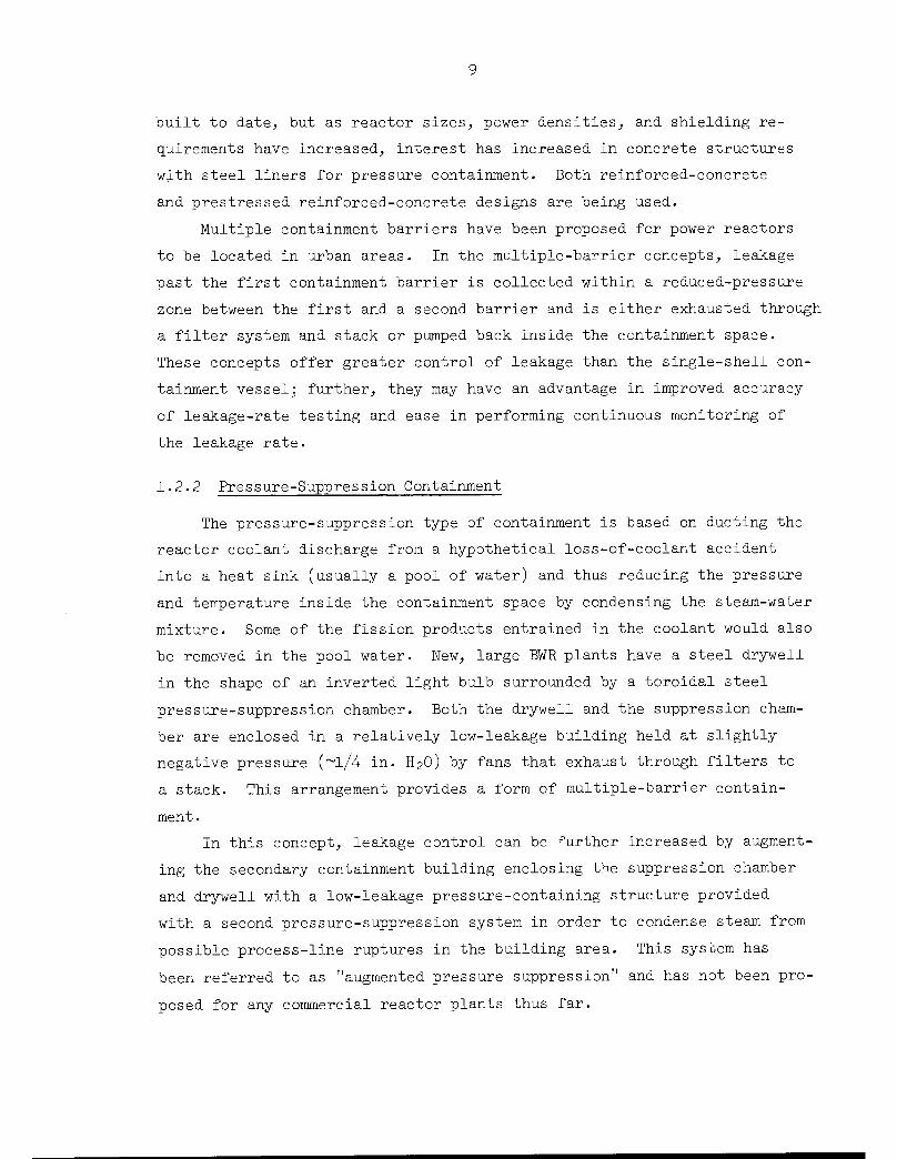
1.2.2 Pressure-Suppression Containment
The pressure-suppression type of containment is based on ducting the
reactor coolant discharge from a hypothetical loss-of-coolant accident
into a heat sink (usually a pool of water) and thus reducing the pressure
and temperature inside the containment space by condensing the steam-water
mixture. Some of the fission products entrained in the coolant would also
be removed in the pool water. New, large BWR plants have a steel drywell
in the shape of an inverted light bulb surrounded by a toroidal steel
pressure-suppression chamber. Both the drywell and the suppression cham
ber are enclosed in a relatively low-leakage building held at slightly
negative pressure (~l/4 in. H20) by fans that exhaust through filters to
a stack. This arrangement provides a form of multiple-barrier contain
ment.
In this concept, leakage control can be further increased by augment
ing the secondary containment building enclosing the suppression chamber
and drywell with a low-leakage pressure-containing structure provided
with a second pressure-suppression system in order to condense steam from
possible process-line ruptures in the building area. This system has
been referred to as "augmented pressure suppression" and has not been pro
posed for any commercial reactor plants thus far.

10
For the latest BWR plants the drywell and pressure suppression cham
bers are designed for the same pressure, and therefore it is possible to
test the strength and leakage rate of both vessels simultaneously. Hu
midity measurements are more critical in a pressure-suppression contain
ment leakage-rate test than in other types of containment because of the
large exposed surface of water.
A recent development in pressure-suppression containment concepts
is the Westinghouse ice condenser reactor containment system, which pro
vides ice to condense any steam accidentally released within the contain
ment structure. The ice is housed in a cold-storage compartment sur
rounding the nuclear steam supply system and is kept frozen by conventional
refrigeration equipment. An increase in pressure in the nuclear compart
ment would activate the access panels located at the bottom of the ice
storage compartment and permit steam and/or hot air to flow through the
ice condenser bed and pass into the top discharge compartment via top
access panels. This system reduces the size of PWR containment structures
based on a lower design pressure and would eliminate a prolonged rise in
containment pressure. The claim is made that reliability is increased,
since no rotating equipment is required to activate the system.
If the AEC allows the reduction of containment design pressures from
approximately 47 psia to about 10 to 15 psig this will imply a reduced
design-basis-accident pressure (and associated temperature) and will in
fluence leakage-rate testing procedures. Westinghouse is proposing the
Absolute Method for leakage-rate testing the three containment compart
ments (pressure shell, ice storage, and discharge) shown in Fig. 1.1.
A reduced test pressure requirement would help to reduce the hazards
involved in testing and make it possible to conduct periodic leakage-rate
tests at full design-basis-accident pressure. Data obtained with a con
tinuous low-pressure leakage and leakage-rate monitoring system would not
require too great an extrapolation to the design-basis-accident pressure
conditions. The ice-condenser concept might reduce the requirements of
the containment air cooling system and could influence containment spray
philosophy.

11
Another concept that is similar to pressure containment is subatmo-
spheric containment, in which steam-ejector and vacuum-pump systems are
utilized to maintain a relatively large negative containment pressure
(~10 psia) during reactor operation. The claim is made that following
a loss-of-coolant accident the containment pressure would be quickly
(25 to 60 min) reduced by a recirculation spray system to subatmospheric
pressure, and thereby all subsequent leakage would be eliminated. Ex
cessive inleakage following the initial pressure excursion would require
the continuous operation of a vacuum pump to maintain a slight negative
pressure. The pumping system would discharge activity to the atmosphere
through a stack.
1.2.3 Conventional Buildings as Containment Structures
Structures similar to conventional buildings are often used to house
the reactor refueling equipment and act as secondary low-pressure con
tainment structures. Containment structures of this type are often op
erated at reduced pressure; that is, leakage from the building is pre
vented by maintaining a ventilation system flow rate sufficient to produce
a slightly negative pressure within the buildings so that all leakage is
inward. The ventilation exhaust is usually directed up a stack; provisions
for filtering are available in the event filtering is required. Leakage-
rate testing of this type of structure is discussed in Chapter 3 of this
report.
1.3 Leakage Rates
Containment leakage rate is one of the factors that enters into the
determination of off-site radiation doses due to design-basis accidents.
Generally, in large nuclear power plants, the lowest leakage rate verifi
able by test is not adequate, without the action of other engineered
safety features, to meet the AEC's siting guides of 10 CFR 100 (Ref. 4).
Leakage rates of 0.1 to 0.5% per day are usually specified as the maximum-
allowable design-basis-accident leakage rates. (The design-basis-acci
dent leakage rate is the leakage rate at the maximum containment oper
ating pressure (calculated peak pressure) that is applied in the safety

12
analysis to evaluate the consequences of containment leakage under the
calculated design-basis-accident conditions, in accordance with the site-
exposure guidelines set forth in 10 CFR 100.) The leakage rate, together
with the action of engineered safety features, must be consistent with
the AEC siting requirements.
When new engineered safety features have been developed, including
new pressure-suppression concepts and improved fission-product-collection
devices, and their performance and reliability have been successfully
demonstrated, perhaps the present maximum design-basis-accident leakage
rates can be appreciably increased. Such an increase would simplify the
process of leakage-rate testing and improve reliability. On the other
hand, multiple-barrier containment designs may be required if hazards
considerations dictate lower maximum-allowable leakage rates or more
positive control of leakage than can be achieved by single-shell contain
ment vessels. If the secondary containment space did not contain a
cleanup system, or if the cleanup system became inoperative, containment
effectiveness would still be considerably improved because of the addi
tional holdup time and opportunity for deposition and plate out of fis
sion products the secondary space would provide. Because some leak paths
are more important than others and gross leakage measurements may give an
overly pessimistic picture of the accident situation, sophisticated acci
dent analyses give consideration to the holdup time provided by conven
tional structures surrounding the primary containment system.
Robertson5 has pointed out that if a containment volume of 2,000,000
ft3, a leakage rate of 0.1% in 24 hr, containment conditions of 55 psia
and 150CF, and the properties of steam are assumed, the leakage can be
represented by that from a hole with a diameter of about 0.06 in. Con
sidering the size and complexity of reactor containment systems, limit
ing leakage to that from a l/l6-in.-diam hole is quite a formidable re
quirement .
Most of the containment systems for large pressurized-water reactors,
including plants now being designed, have a maximum-acceptable design-
basis-accident leakage rate of approximately 0.1% in 24 hr. Since the
major portion of the plant is usually enclosed within the containment

13
vessel, the free volume is large and one-thousandth of this volume repre
sents a quantity that is just compatible with the measuring methods which
have been used.
Although leakage rates as low as 0.1% per day have been apparently
achieved, leakage rates much less than this (say 0.01% per day or less)
may be very difficult to demonstrate for single-barrier containment sys
tems because of the limited sensitivity of available leakage-rate test
ing methods, even though it might be possible to actually achieve such a
low leakage rate by careful design and construction.
All boiling-water reactors have some type of pressure-suppression
system (which can also entrain fission products) and have a smaller con
tainment volume than is used for pressurized-water reactors of similar
power; consequently, the BWR containment systems would be at a high pres
sure for a shorter time in the event of an accident. In addition, BWR
plants are also enclosed in a secondary building that has a filtering
system and stack that would retard the spread of any fission products re
leased from the primary containment system.
After a containment structure has been completed and prior to li
censing and initial operation (usually prior to installation of reactor
pressure vessel and core), preoperational leakage-rate tests are usually
performed at the maximum accident pressure and at a lower pressure that
is to be used for subsequent retesting purposes. The lower testing pres
sure and its associated allowable test leakage rate (at ambient tempera
ture and air atmosphere) is determined by the reactor operator organiza
tion and his consultants based on negotiations with the AEC Division of
Reactor Licensing and is stated in the technical specifications that be
come part of the operating license. The higher accident test pressure
and its allowable test leakage rate (at ambient temperature and atmo
sphere) does not appear in the technical specifications.
The results of the preoperational tests, the maximum design-basis-
accident pressure and temperature, and the associated allowable leakage
rate at accident conditions are usually presented in the final safety
analysis report. The allowable leakage rate at the maximum accident
pressure based on accident fluid composition and state is the basic

14
parameter used to establish all other test and operational allowable leak
age rates. The calculations that establish the allowable test leakage
rates do not normally appear in any formal document.
1.4 Containment Accident Conditions
The design-basis-accident leakage rate is directly related to the
transient conditions within the containment structure following a major
accident. Pressure, temperature, steam-air composition of the contain
ment atmosphere, and fission-product release and transport are all parame
ters that must be considered in arriving at a reasonable allowable leak
age rate. Typical BWR and PWR postaccident containment pressure response
curves are shown in Figs. 1.2 and 1.3 (Refs. 6 and 7).
The BWR curve shows that in approximately 30 to 80 sec after an ac
cident the pressures in the dry well and suppression chamber (wet well)
would equalize to approximately 21 to 25 psig. After this time the pres
sure response would depend on the successful operation of various engi
neered safety features. If no safety features were activated, the
TIME AFTER ACCIDENT (seconds)
Fig. 1.2. Typical BWR Containment-Pressure Response Following aMajor Accident. (From Ref. 6)

15
i i 11 inn i i i i imii i I ii mil i ii i inn i i i i miKEY
I - NO SAFETY FEATURES
II - SAFETY FEATURES INCLUDE AIR RECIRCULATION (3 FANS IN OPERATION)III - SAFETY FEATURES INCLUDE AIR RECIRCULATION (4 FANS IN OPERATION)
IV- SAFETY FEATURES INCLUDE AIR RECIRCULATION (4 FANS) AND SPRAY SYSTEM
V- SAFETY FEATURES INCLUDE AIR RECIRCULATION (4 FANS)AND SAFETY-INJECTION SYSTEM ""
VI- SAFETY FEATURES INCLUDE AIR RECIRCULATION (4 FANS)SPRAY SYSTEM, AND SAFETY-INJECTION SYSTEM
"VDE;0ES1GN PRESSURE
V)
JJJLiULo'
ALL PRIMARYCOOLANT DISCHARGEDINTO CONTAINMENTSTRUCTURE
safety-injection system stops-
iInun i iimini i iiiurn Tl iK>z 10*
Fig. 1.3. Typical PWR Containment-Pressure Response Following aMajor Accident. (From Ref. 7)
pressure would continue to rise and eventually would exceed the contain
ment design pressure. As can be seen from Fig. 1.2 the pressure response
is related to the number of core spray and containment air-cooling or
spray systems that are successfully operated following the accident.
The typical PWR pressure response (Fig. 1.3) indicates a steep rise
to approximately 38 to 48 psig within 8 to 20 sec, followed by a reduc
tion in pressure, and then a second rise to a maximum pressure just be
low design pressure after 4 to 20 min. This response is typically based
on partial safety feature operation. Again, if no safety features were
activated, the pressure would continue to rise and would exceed the con
tainment system design pressure. Following the original pressure in
crease the pressure transient would be related to the number and type of
engineered safety features operational following the accident.
A theoretical fission-product release curve is shown in Fig. 1.4.
The curve only indicates a probable time and magnitude relationship rela
tive to the pressure transient following an accident in either a BWR or

16
10' 10 10 10J
TIME AFTER ACCIDENT (sec)
ORNL-DWG 68-8742
10'
Fig. 1.4. Typical Fission-Product Release Following a Major Acci-dent.
PWR reactor. This curve is based on the theory that a few fuel element
failures would occur after about 20 to 30 sec following the initial ac
cident and that the mechanism for displacing the fission products is the
new steam formed from the injected core spray coolant. The maximum re
lease would coincide with the related decrease in pressure due to the
spray addition, and the release rate would subside rapidly after the
peak was reached.
The USAEC document9 on "Calculations of Distance Factors for Power
and Test Reactor Sites" provides an analytical method for calculating
siting distances and gives reference information and guidance on proce
dures and basic assumptions for reactor siting. As stated in this docu
ment:
"It is assumed that the reactor is a pressurized watertype for which the maximum credible accident will release intothe reactor building 100 percent of the noble gases, 50 percentof the halogens and 1 percent of the solids in the fission product inventory. Such a release represents approximately 15 percent of the gross fission product activity.
"The release of available (airborne) radioactivity fromthe reactor building to the environment is assumed to occur ata constant leakage rate of 0.1 percent per day. The leakage andpressure conditions are assumed to persist throughout the effective course of the accident, which for practical purposes, wouldbe until the iodine activity becomes insignificant. The maximum
pressure within the reactor building and the leakage rate wouldactually decrease with time as the steam condenses from contactwith cooling surfaces. By assuming no change in leak rate as

17
a function of pressure drop, it is estimated that the final off-site doses calculated may be too high by factors of 5-10.
"The exact release can vary so much with the reactor systemand with the detailed nature of an accident that the degree ofconservatism in the assumptions made in any given case, is notknown. Further, there is a multiplicity of possible combinations of the physical and chemical form of the radioactive materials released into the containment vessel and of the waysthat atmospheric conditions might cause these radioactive materials to be transported to regions beyond the site boundary."
These quotations are indicative of the AEC philosophy used in estab
lishing leakage rates. There are many factors that contribute to the
difficulty of determining the exact radioactive fission-product content
of the containment atmosphere and the actual transient pressure condi
tion that provides the driving force required to produce containment leak
age. (Additional information on fission-product release and dispersion
can be found in Chapters 4 and 7 of Ref. 1.)
Estimates of radiological releases due to design-basis accidents are
made by license applicants and by the AEC Staff. The applicant's prelimi
nary safety analysis report (PSAR) usually presents optimistic assumptions
and calculations that result in very low estimated dose rates. Credit is
always taken for some containment safety features, such as containment
spray or air cooling, and in most cases in-core cooling. The calculated
dose rates are shown to be very low, and indeed statements to the effect
that the rates are far below the guideline radiation doses given in
10 CFR 100 are presented to indicate ample margin to absorb much larger
fission-product releases than those postulated and still adequately pro
tect the public.
In reviewing the PSAR, the AEC staff uses procedures similar to those
described in Ref. 9, which postulates an initial release to the contain
ment system of approximately 15% of the gross fission-product activity,
whereas the applicants use approximately 1% or less. Discrepancies in ex
posure dose rates calculated by the AEC staff and by applicants can range
from factors of 100 to 500,000.10> 1:L These differences are accounted for
by differences in the detailed chain of phenomena involved in the release
and transport of activity. The 15% release is representative of a total
core meltdown accident. It should be pointed out that the meltdown

18
accident is only a model used for calculating the dose to the public and
not the sole factor in evaluating containment integrity. Table 1.1 shows
the estimated degrees of conservatism in exposure calculations based on
Ref. 9, which indicates that there are potential, conceivable conditions
that could result in fission-product releases larger than those assumed
and that the consequences could be much more hazardous. A core meltdown
accident presents no radiological danger to the public so long as the
containment system functions properly and other containment safety fea
tures, such as air cooling, spray, and filtering systems, are success
fully operated.
However, the basic assumption of a complete core meltdown is incom
patible with containment integrity unless some device or system is pro
vided to confine the molten heat source (~30 to 40 Mw for a large reactor)
within the containment envelope.
Table 1.1. Estimated Degrees of Conservatism
in Exposure Calculationsa
Calculation or AssumptionDegree of
Conservatism
Removal of iodine from containment vessel 3—10
atmosphere by various physical phenomena,such as adsorption, adherence, and settling
Removal of iodine by protective safety features, 10—1000such as cooling spray and filtration of internal-air-recirculating systems
Vessel leakage rate calculated at constant peak 5—10pressure
Wind direction shift during extended period of 2—50
time
Wind meandering from center-line direction ~3
Atmospheric dispersion under other than inver- 5—1000sion conditions
Particulate fallout from radioactive cloud 2—5
Direct gamma dose, with shielding from struc- 2—1000
tures and topography neglected
From Ref. 1.

19
Criterion 49 of the AEC General Design Criteria for Nuclear Power
Plants12 requires the design of a containment structure or system to ac
commodate an accident in which the emergency core-cooling system fails
to function, therefore (without regard for the Chinese Syndrome dilemma13)
the engineered safety features of containment systems must be designed,
built, installed, tested, maintained, and operated in the most reliable
manner possible. Some form of containment cooling is essential to pre
vent destruction of the containment vessel due to overpressure. Further,
there can be no compromise in the manufacturing and inspection procedures
used for individual system components, and many off-the-shelf items will
not be adequate. Recent trends in electrical equipment failure appear
to bear out the need for tightening quality-control specifications.14
1.5 Purpose of Containment System Testing
The purpose of containment systems testing is to provide assurance
that the containment structure and associated engineered safety features
will function as designed in the event of an accident. The methods of
conducting these tests, as well as the considerations that go into de
termining the frequency of periodic tests, are discussed further in
other sections of this report.
The basic objective is to design and build an integrated contain
ment system that will prevent or minimize radioactive releases to the
atmosphere in case of a serious accident to the primary system. Reli
ability and testing requirements must be considered in the initial de
sign stages. The major difficulty in evaluating containment system
tests (especially leakage-rate tests) is the relationship between acci
dent and testing conditions. Correlations between the two conditions
must be developed before ambient-temperature air-leakage rate data can
be quantitatively applied to accident analysis. This type of information
can then provide a basis for establishing meaningful ambient-temperature
leakage-rate criteria.
A typical listing of accident and testing conditions, given in
Table 1.2, indicates that leakage-rate testing conditions only simulate
one parameter versus four or more parameters that represent the accident

20
Table 1.2. Comparison of Accid.ent and ContainmentSystems Testing Conditions
Conditions
Parameters
Atmosphere
Temperature
Pressure
Induced stresses
During Accident
Steam plus air plusradioactive particles and gases
Increasing
Increasing
Transient thermal
and pressure
^Measured with strain gages.
During Testing
Dry air
Ambient
Maximum for design-basis accident
Pressure3,
conditions, and this is only during the preoperational leakage-rate test
at design-accident pressure conditions. Subsequent surveillance testing
is with air at some lower test pressure.
An outline of the general types of containment system testing is
given below:
Vessels and Penetrations
1. Strength
2. Periodic local
a. Leak
b. Leakage rate
3. Periodic integrated leakage rate
a. Maximum accident pressure
b. Intermediate pressure
c. Low pressure
4. Continuous
a. High-pressure local leakage rate
b. Low-pressure integrated leakage rate

21
Spray, Air-Cooling, and Heat-Removal Systems and Valves
1. Strength
2. Leak
3. Leakage rate
4. Performance
The usual testing sequence is the following:
Bare-Vessel Tests
1. Strength
2. Leak
3. Leakage rate
Preoperational Tests
1. Strength
2. Leak
3. Leakage rate
4. Performance
Periodic Surveillance
Continuous Surveillance
Strength testing is repeated under preoperational tests because this
test will probably be performed just prior to the required preoperational
integrated leakage-rate tests associated with metal-lined concrete con
tainment vessels. This procedure results in a minimum containment vessel
pressure-time exposure consistent with present AEC testing requirements.
The following general types of tests are performed to provide in
creased assurance that in the event of a serious accident, the contain
ment structure leakage rate will be within allowable limits.
1.5.1 Strength Testing
The purpose of strength testing is to demonstrate that the contain
ment structure has been designed and constructed so that it will subse
quently be able to contain the design pressure without failure. These
tests are conducted in accordance with the procedures presented in Sec
tions III and VIII of the ASME Boiler and Pressure Vessel Code.

22
1.5.2 Integrated Leakage-Rate Testing
Integrated leakage-rate testing at relatively high pressure is per
formed initially and at intervals during the life of a reactor plant to
confirm the leaktightness of the containment structure. Although inte
grated leakage-rate testing has often been performed immediately after
completion of the vessel and prior to installation of penetrations and
isolation valves, tests performed at this time are not very meaningful
and will probably be performed less in the future. This prepenetration
test is not required by the AEC but is a contractual requirement to insure
the purchaser that the vessel supplier has built a vessel that is suffi
ciently airtight prior to the installation of penetrations and isolation
valves. A development that is receiving more attention is continuous
low-pressure integrated leaivage-rate testing performed while the plant
is operating at power. This testing has the primary purpose of insuring
that during operation no appreciable changes occur in the integrated
containment leakage rate as a result of such incidents as leaving an air
lock open, failing to close a purge line, failure of valve packing, etc.
Experience to date indicates, however, that this technique will also
detect small changes in leakage rate (comparable to the allowable rate)
within 30 to 60 days.
1.5.3 Leakage Surveillance Testing
Leakage surveillance testing is the testing performed on those com
ponents most likely to leak, such as penetrations, isolation valves, air
locks, etc. These tests are normally performed more frequently than inte
grated leakage-rate tests, since successful performance in these tests
permits inference of a high probability that leakage measured in an inte
grated leakage-rate test of the complete containment system will not be
excessive. These tests are usually performed by pressurizing the compo
nent in question and then monitoring leakage by measuring pressure decay
or by other means. In some cases, surveillance testing is conducted
continuously by maintaining an internal pressure on the penetration and
monitoring the pressure decay when the plant is operating. It has been
argued that continuously pressurizing penetrations to full accident
23
pressure will decrease the probability of leakage through these penetra
tions should an accident occur. This is due to the zero or negative
pressure gradient, which in turn prevents outleakage of the containment
atmosphere. It is not clear that this degree of conservatism is warranted,
particularly if constant penetration pressurization were made a require
ment for power operation, and failure of the pressurization system could
necessitate shutdown of the reactor plant. From the standpoint of direc
tion of leakage under accident conditions, a negative pressure or vacuum
test would be preferable.
1.5.4 Engineered Safety Feature Testing
The purpose of testing engineered safety features is fairly obvious —
to provide the reactor operator with assurance that these vital systems
will operate properly in the event of an accident that requires their
use. Achievement of this purpose is complicated by the fact that it is
usually impossible to test the engineered safety features under actual
accident conditions (with the containment system pressurized with steam).
In some cases, use of operating equipment that is normally operating
(containment air coolers, for example) to provide containment cooling in
the event of an accident provides a high degree of assurance that the
equipment will be operating at the time when an accident occurs. This
is another form of continuous testing that is similar to the continuous
low-pressure Integrated leakage-rate test.

24
2. APPLICABLE CODES, STANDARDS, ANDREGULATORY REQUIREMENTS
Design codes usually refer to nationally recognized standards and
represent only minimum requirements. Each containment system is reviewed
for conformance to governing legal criteria and for adequacy of provisions
for public safety. The majority of codes do not have legal status; how
ever, many cities and states have adopted sections of codes and, as such,
those sections attain legal status. The standards, codes, and guides
associated with containment system testing are primarily used as guides
by plant designers and operators.
The AEC regulatory staff can request that various codes, guides, and
standards be referenced in construction and operating license documents
and, because of this, the referenced documents acquire legal status. The
AEC Division of Reactor Standards has also developed its own series of
documents to establish minimum standards from AEC's viewpoint of responsi
bility for safety — "Safety Standards, Criteria, and Guides for the Design,
Location, Construction, and Operation of Reactors." Included in this
series is Part III. Technical Safety Guide — Reactor Containment Leakage
Testing and Surveillance Requirements, which is now being used by the
Division of Reactor Licensing as a guide in establishing leakage-rate test
ing requirements. Because of its importance, this guide is discussed sepa
rately in Section 2.2 below and is included in this report as Appendix B.
Other codes, standards, and guides representing those that are now
being applied or are being referenced In documents related to containment
testing are discussed in Section 2.1. Table 2.1 lists all existing and/or
planned documents that pertain to or are indirectly associated with con
tainment system testing.
2.1 Codes, Standards, and Guides
Water-cooled and -moderated power reactors are entering a design and
construction phase in which many design features are being standardized.
A number of "standards" have been written to cover various phases of design,
fabrication, and testing of reactor plant containment systems, and these

SponsoringOrganization3
ACI
ACI
ANS
API
ASCE
ASME
ASME
ASME
ASME
IEEE
USASI
USASI
USASI
USASI
Standards Committee
Committee 349
Committee 318
ANS-7
Division of Refining
Task Committee on
Nuclear Materials
ASME Boiler and
Pressure Vessel
Code Committee
ASME Boiler and
Pressure Vessel
Code Committee
ASME Boiler and
Pressure Vessel
Code Committee
WG-1, ElectricalPenetration
Assemblies
N6.2
B 31
B 31
N6.9
25
Table 2.1. 1uainiuent System Testing — Related Codes,
Chairman, Address
Raymond C. Reece,Raymond C. Reece Associates,P. 0. Box 556, Toledo, Ohio
Raymond C. Reece,Raymond C. Reece Associates,P. 0. Box 556, Toledo, Ohio
S. S. Bacharach,Aerojet-General Corp.,
Sacramento, Calif.
Division of Refining,
American Petroleum Inst.,1271 Avenue of the Americas,New York, New York
S. H. Fistedis,Argonne National Laboratory,
Argonne, Illinois
American Society of Mechanical
Engineers, United EngineeringCenter, 345 E. 47th St.,New York, New York
B. F. Langer,Westinghouse Electric Corp.,Bettis Plant, Pittsburg,Pennsylvania
C. Rogers McCullough,
Southern Nuclear Engineering Co.,Dunedin, Florida
W. R. Smith,General Electric Co.,175 Curtner Ave.,
San Jose, Calif.
H. W. Meswarp,Gibbs & Hill, Inc.,393 Seventh Ave.,New York, New York
R. N. Bergstrom,Sargent & Lundy Engineers,
140 S. Dearborn St.,Chicago, Illinois
E. C. Pandorf,Cincinnati Gas & Electric Co.,
P. 0. Box 960,Cincinnati, Ohio 45201
W. R. Gall,Oak Ridge National Laboratory,P. 0. Box X,Oak Ridge, Tenn. 37830
W. B. Cottrell,Oak Ridge National Laboratory,
P. 0. Box Y,Oak Ridge, Tenn. 37830
Codes and Standards Activities
Criteria for concrete containment
structures for nuclear reactors
Building code requirements for
reinforced concrete
Leakage rate testing of containmentstructures for nuclear reactors
Recommended rules for design and
construction of large, welded,low-pressure storage tanks
Testing of containment capabilities
of reinforced-concrete enclosures
Rules for construction of unfired
pressure vessels
Boiler and Pressure Vessel Code,
Sect. Ill, Nuclear Vessels
Criteria for concrete reactor ves
sels for nuclear plants
ASME code for pumps and valves for
nuclear service
Guide for electrical penetrationassemblies in containment struc
tures for stationary nuclear power
plants
Safety standard for design, fabrication, and maintenance of steel containment structures for stationary
nuclear power reactors
American standard code for pressure
piping
American standard code for nuclear
power piping
Compilation of U.S. nuclear
standards
Standard
Number
318
Status
Active
Date of
Standard or
Latest Draft
Approved 1963
ANS-7.60 Active June 1967
API-620 Approved Nov. 1966
ANL-6664 Approved March 1963
Sect. VIII Approved 1965
Sect. Ill Approved 1965
Active
Active Nov. 1966
Active Sept. 1966
N6.2-1965 Approved April 1965
B31.1 Approved 1955
B31.7 Active Feb. 1968
Approved 1966
Remarks
Task group preparing criteria toinclude reinforced and pre-stressed designs; cooperatingwith ASME group
Periodically reissued
Approved by ANS June 14, 1967
Third edition
Issued as an informal document
Addenda issued twice a year
Addenda issued twice a year;
often refers to Sections II and
IX of the Boiler and Pressure
Vessel Code
Task group preparing criteria to
include reinforced and pre-
stressed designs
Tentative draft issued for
comments
Proposed seventh revision issuedfor comments
Addenda issued; sponsored by
ASME
Tentative draft issued for com
ments; sponsored by ASME
Reissued annually
Code to sponsoring organizations:
ACI — American Concrete Institute
ANS — American Nuclear SocietyAPI — American Petroleum Institute
ASCE — American Society of Civil Engineers
ASME — American Society of Mechanical Engineers
IEEE - Institute of Electrical & Electronics Engineers
USASI - United States of America Standards Institute

26
are very helpful. However, their use to design specific equipment items,
such as penetrations, valves, etc., should be avoided, since this would
tend to fix designs at a minimum level and could result in the subjugation
of design initiative and progress in the development of safer and more re
liable reactor plants. Such further development is particularly desirable
because of the strong incentive to locate reactors in urban areas. Use of
standards primarily as guides, as well as use of codes similar to the ASME
Power Test Codes or the Instrument Society of America's Tentative Recom
mended Practices, is appropriate at this phase of the industry's develop
ment .
The Atomic Energy Acts of 1946 and 1954 placed many areas of the
nuclear industry under the regulatory control of the government. However,
the development of nuclear standards in the United States is, at present,
primarily the responsibility of the various technical societies, scien
tific organizations, trade associations, manufacturers, and other groups
directly affected by these standards. To be useful, a standard must be
approved by all affected organizations.
The United States of America Standards Institute (USASI) was created
in 1966 as the successor to the American Standards Association in order
to expand the program and to accelerate the output of voluntary national
standards serving the entire economy. Standards approved by the new
Institute are designated USA Standards. This designation also applies
to all previously approved American Standards. Broader participation by
all interested groups, including departments and agencies of the Federal
Government, increased representation and leadership in the international
standards programs, and emphasis on consumer interests are major objectives
of the Institute.
Three councils make up the operating arms of the Institute. These
are (l) the Member Body Council, which is responsible for standards activi
ties, (2) the Consumer Council, and (3) the Company Member Council. Con
sumer representatives and company representatives can recommend areas for
the development of appropriate standards. They can request the opportu
nity to review and approve or disapprove any standard. The new Consumer
Council has representation from the Member Body and Company Member Councils
and five members who need not be representatives of Institute members and

27
who are appointed by the Executive Branch of the Federal Government. The
Consumer Council is concerned primarily with the application of the Insti
tute's procedures for certification and labeling of consumer goods.
Approval of USA Standards is based on consensus of all parties con
cerned. The hundreds of national trade associations and technical, pro
fessional, and scientific societies that develop standards and work with
the Institute are encouraged to extend this consensus principle to their
own operations. The Institute, under the terms of its constitution, is
not permitted to develop standards on its own. It does, however, promote
and accent the development of needed standards by appropriate, competent,
and accepted organizations and provide the mechanism for approval and dis
semination of standards.
There are many company standards and technical society standards that
have never been submitted to USASI for approval. Such standards are none
theless valid when accepted by those concerned, and some are nationally
recognized. An informal cooperative relation is maintained between USASI
and the AEC, since industry standards and government regulations should
be compatible. Although many groups are involved in the production of
standards through USASI, technical and professional societies with nuclear
interest also prepare and publish documents that are regarded as standards
as far as the particular society Is concerned.
A comprehensive review of nuclear containment system codes and stan
dards is included in Section 2 of "U. S. Reactor Containment Technology,"1
and compilations of all U.S., foreign, and international nuclear standards
are issued yearly by the Nuclear Safety Information Center located at Oak
Ridge National Laboratory. The major codes, standards, and guides that
affect reactor containment systems testing are described briefly below:
1. USA Standard. N6.2—1965, Safety Standard for Design, Fabrication
and Maintenance of Steel Containment Structures for Stationary Nuclear
Power Reactors. This standard outlines suggested practice for the design
and construction of welded steel-shell containment vessels. Its purpose
is to assure, through the proper design, fabrication, and maintenance of
containment structures, that radioactive material cannot be dispersed from
nuclear power reactors in a manner that would be harmful to personnel or
the public. The Standard is limited to welded steel shells, and it includes

28
specifications on materials, allowable stress values, shell and head de
sign, design of openings and penetrations, spacing of openings, welding,
containment insulation, and foundation and support requirements. Data are
also provided on pressure testing for strength, leakage testing, periodic
Inspection and testing, etc.
The leakage-rate testing provisions of the Standard, although in less
detail and somewhat more limited in application, are generally consistent
with the provisions of the ANS Standard described below.
2. ANS Standard 7.60, Proposed Standard for Leakage-Rate Testing of
Containment Structures for Nuclear Reactors (Latest draft dated June 1967).
This proposed standard suggests techniques for local leak detection and for
both reference and absolute methods of integrated leakage-rate testing of
containment vessels. It reflects the practice that has generally been used
in the past and which might be expected to be followed in the future. The
provisions of the proposed standard apply "to containment structures for
nuclear power, test, research, and training reactors, wherever a gastight
containment structure is specified as a condition for operation." (See
Appendix C.)
3. Proposed Criteria for Concrete Containment Structures for Nuclear
Reactors. This proposal is being prepared by ACI Committee 349, which was
recently organized by the American Concrete Institute to develop criteria
and design codes for concrete containment vessels. Several meetings have
been held and there are hopes that criteria may be available soon.
4. ACI Code 318, Building Code Requirements for Reinforced Concrete.
This is the standard of the American Concrete Institute for the design of
reinforced-concrete structures. Although it does not strictly apply to
concrete pressure vessels, its provisions may be applied to any reinforced-
concrete structure, and it is used to the extent it applies for concrete
containment vessels.
5. ASME Boiler and Pressure Vessel Code, Section VIII, Unfired Pres
sure Vessels (Latest edition, 1965; applied when referenced in Section III
of the Code). This well-known code and several code interpretations re
lating it specifically to containment vessels have been used in the design
of most existing containment structures. It defines structural design and

29
testing requirements for welded steel-shell pressure containment vessels.
Addenda are issued twice a year (summer and winter) to keep the code up
to date.
6. ASME Boiler and Pressure Vessel Code, Section III, Nuclear Ves-
sels (Latest edition, 1965). This portion of the ASME code was first
issued in 1963 to define the special requirements for all nuclear vessels.
Subsection A applies to reactor primary pressure vessels and is the largest
section of the code. Subsection B applies to containment vessels. This
code covers the minimum construction requirements for the design, mate
rials, fabrication, testing, and certification of vessels for use in nu
clear power plants. Separate addenda are also issued twice a year (summer
and winter) for nuclear vessels.
7. API Standard 620, Recommended Rules for Design and Construction of
Large, Welded, Low-Pressure Storage Tanks. This standard of the American
Petroleum Institute applies specifically to large liquid and gas storage
tanks used in the petroleum industry. It has been referred to in a few
cases for low-pressure containment vessels designed for pressures below
those for which the ASME codes are applicable.
8. B31.7, Nuclear Piping (Latest draft, January 1968). This tenta
tive code is a section of the USA Standard Code for Pressure Piping spon
sored by the ASME and as such is part of USA Standard B31. This code pre
scribes minimum requirements for the design, materials, fabrication,
erection, testing, examination, and inspection of piping in nuclear power
plants. Its rules provide minimum safety requirements of both steady and
fluctuating loads, including thermal stresses that may be expected in the
intended service.
9. ASME Code for Pumps and Valves for Nuclear Service (Latest draft,
November 1966). This code covers requirements for the design, materials,
manufacture, examination, inspection, static testing, and certification of
pumps and valves for use in the nuclear energy system of any water-cooled
nuclear power plant. Pumps and valves for which rules are specified by
this code are those designed to provide a pressure-retaining barrier in a
nuclear energy system or for the overall containment of the system. These
rules provide requirements for new construction. They cover mechanical

30
and thermal stresses due to cyclic operation but do not yet cover deteri
oration that may occur in service as a result of radiation effects and
instability of material.
10. Guide for Electrical Penetration Assemblies in Containment Struc
tures for Stationary Nuclear Power Reactors (Proposed, latest revision,
September 1966). This document, which was issued by IEEE, covers mechani
cal, electrical, and test requirements for design and installation of
electrical penetration assemblies in vapor-containment structures for
nuclear power reactors. The requirements and specifications for vapor-
containment structures are inherent in the nuclear safeguards evaluation
for the particular reactor. At the present time it is not feasible to
establish standards for electrical penetration assemblies independent of
these other considerations. Accordingly, this document is intended as a
guide and delineates requirements that must be considered to assure that
electrical penetration assemblies are consistent with the overall require
ments for containment.
2.2 AEC Technical Safety Guide
The AEC guide entitled "Reactor Containment Leakage Testing and Sur
veillance Requirements" (see Appendix B for latest revised draft, Dec. 15,
1966), was prepared by the AEC Division of Safety Standards. It is Part
III, Technical Safety Guide, of a draft of a document entitled "Safety
Standards, Criteria, and Guides for the Design, Location, Construction,
and Operation of Reactors" and was made available to the Division of Re
actor Licensing for interim guidance in establishing leakage-rate testing
and surveillance requirements for reactor containment vessels.
The guide outlines specific relations for establishing test leakage
rates based on the initial limit of leakage rate under design basis acci
dent conditions, and it suggests a containment retesting schedule that many
industrial representatives believe does not give enough credit for such
systems as continuous penetration monitoring, weld-channel monitoring, and
continuous low-pressure integrated containment leakage monitoring. Some
credit or advantage is gained by using these systems, since (l) the use of
a continuous penetration monitoring system eliminates the need for class B

31
tests (penetration tests), (2) weld-channel monitoring reduces the risk
of leakage development at weld areas which, if undetected, could contrib
ute to excess leakage and result in a penalty of more frequent integrated
tests, and (3) continuous low-pressure leakage monitoring surveillance of
the conditions of the containment system assures the plant operator that
containment integrity is maintained to the degree that no gross leaks have
developed (based on limits of accuracy of the continuous monitoring tech
nique employed).
The Division of Reactor Licensing uses the Technical Safety Guide
only as a guidance document and does not rigorously apply it. An example
of this is the leakage rate specified for the San Onofre Reactor,15 which
has the design-basis-accident leakage rate as the allowable leakage rate
under test conditions and thereby neglects the correction factors for tem
perature and air testing conditions. While this leakage rate does not
result in excessive exposures with respect to the guideline set forth In
10 CFR 100, there is still an inconsistency with the Technical Safety Guide
In the method of applying the relative leakage-rate factors. Another ex
ample is that a summary technical report which includes specific informa
tion about the test is suggested in the guide, but it is seldom required
that such a report be submitted officially.
A previous issue of the guide (January 15, 1966) indicated that plans
were being made to issue the guide for public comment upon completion of
a supporting technical information document that would accompany the guide
and outline the bases for its requirements; however, the latest revision,
dated December 15, 1966, only mentions that the recommended testing and
surveillance program, has evolved from a survey of containment leakage
characteristics and reported testing experiences.
The guide's purpose is stated as follows:
"These minimum test requirements are intended to verifyperiodically the leak-tight integrity of the containmentsystem, and to establish the acceptance requirements of eachtest. The purpose of the tests is to assure that leakage ofthe containment system is held within allowable test limitsand that the periodic surveillance tests assure proper maintenance and repair."
Four types of tests are suggested in the guide. The class A test is an
overall integrated leakage-rate measurement of the containment system.

32
Class B tests are individual local leakage tests, such as at penetrations,
etc., and class C tests are for isolation valves. Class D tests cover
other engineered safety feature systems that influence containment leakage
under postaccident conditions. The guide states that these tests are to
be performed under class A test conditions, although this has not been re
quired in any licensing action completed to date. The requirements for
testing engineered safety feature systems are currently being reviewed,
and the AEC criteria that evolve may influence these requirements.
Either the absolute method or the reference method of leakage-rate
testing (as described In Sect. 3.2 of Chap. 3, this report) Is acceptable,
and the minimum testing time is 24 hr. The initial integrated leakage-rate
tests are performed after completion of the containment structure and In
stallation of all penetrations. These tests are conducted at two pressure
levels, with the first being at 100% maximum containment system operating
pressure. This is the maximum calculated peak pressure for the design-
basis accident. This pressure can be equal to or below the design pressure
of the containment vessel. The second pressure is established as not less
than 50% of the maximum containment system operating pressure. This pres
sure is used for subsequent class A retesting. The two tests measure the
representative leakage characteristics of the containment system. The
reduced-test-pressure leakage-rate test is justified by conducting more
frequent surveillance tests of various containment components, including
valves, at a test pressure equal to the maximum calculated peak accident
pressure. In addition to the two class A preoperational leakage-rate
tests, a third leakage-rate test may be conducted at a lower pressure cor
responding to that maintained during the operation of a continuous leakage
monitoring system.
A method of determining retest schedules is included in the guide
which recognizes that the containment leakage potential and its conse
quences depend on the magnitude of the calculated peak accident pressure
and activity and its corresponding leakage rate as influenced by siting
criteria. More frequent testing is considered necessary where low leakage
rates are specified, since test experiences have shown the difficulty of
maintaining these low rates. It should be noted that if the engineered
safety features operate as intended, the containment system will be at its

33
peak pressure condition for only a short time, and this could, in turn,
represent a sizable safety factor.
A retest schedule provides for a graduated increase in the interval
between tests for the first three class A tests. During this period, the
adequacy of the test program can be evaluated by the observed leakage be
havior of the containment system. The test frequency is then established
at a level governed by the leakage measurements of the successive tests.
Leakage measurements that yield results in excess of allowable test limits
then indicate the existence of deteriorative service conditions or inade
quate maintenance programs during the test interval, and therefore reveal
the need to decrease the interval between successive tests. On the other
hand, leakage measurements within limits attest to the adequacy of the test
program and result in increasing or maintaining the time interval before
the following test. The test schedule reflects this flexible approach of
allowing the observed leakage behavior of the containment system during
service to dictate the test frequency.
The allowable test and operational leakage limits (which are specified
in the technical specifications) establish the acceptance criteria for
class A tests. These limits are determined by adjusting the design-basis-
accident leakage rate to reflect the differences between the calculated
accident and test conditions. A further adjustment is made to account for
testing at pressures other than the calculated peak pressure of the design-
basis accident. Following each class A test and before resumption of plant
operation, the allowable operational leakage rate may be intentionally de
creased to provide a margin for any leakage increase the containment system
may experience in future service. The margin is proportionally adjusted
as the interval between class A tests is extended by the test frequency
schedule.
The guide specifies that all class B tests (individual local leakage
tests) are to be performed by local pressurization at the maximum contain
ment operating pressure. Retesting is required when any leakage rate per
24 hr per component exceeds 0.1% of the maximum allowable test leakage
rate (L ). This approach would allow approximately 1000 such leaks to be
present. The class B retest schedule requires two tests between class A
tests, with one year as a maximum limit. An exception is made for airlocks

34
that are to be retested every four months. Additional retests are re
quired if there is no provision for testing components.
Class C tests, which cover all valves that could cause breaching of
the containment system, include both closure and leakage tests. The piping
between isolation valves is to be pressurized at the maximum containment
system operating pressure, and each individual valve leaka.ge rate per 24 hr
must not exceed 1% of the maximum allowable test leakage rate. This ap
proach would permit operation with each of 100 valves leaking at approxi
mately 1% of the maximum allowable rate. Class C retesting is based on
the schedule of class B tests and must be conducted at least once per year.
The guide states that class D tests (tests of other engineered safety
systems) are to be conducted initially in conjunction with the preopera
tional leakage-rate test at maximum design-basis-accident pressure (P ).
Future tests are then conducted at ambient conditions during class A tests
and at least once a year.
A continuous leakage monitoring system is acceptable to measure or
detect changes in rates provided the system is operated at 10% or more of
the containment vessel test pressure. Leakage rates, testing intervals,
and acceptance criteria are outlined in the guide for continuous monitor
ing systems. Class A tests are also applicable to multiple-vessel and
multiple-barrier containment systems.
The guide specifies that summary technical reports for all class A,
B, C, and D tests are to be submitted. The reports are to include a
schematic arrangement of the leakage-measurement system, the instrumenta
tion employed, the test procedure, test results in graphic form, and the
analysis and interpretation of leakage-rate results in terms of the al
lowable leakage rates specified in the license.
Reactor operating and prime contractor firms appear to be in general
agreement that the underlying basis of the retest schedule was arbitrarily
set by the AEC Division of Reactor Standards, who developed the retest
schedule on the basis of existing containment leakage-rate tests but did
not publish this information. An objective rationale for the retest sched
ule cannot be established at this time; however, the AEC feels that a con
servative approach is prudent, since the maximum accident pressure and
associated temperature probably will increase containment leakage rates.

35
The containment design pressure is usually based on the expected maximum
accident pressure, and it is assumed that the associated leakage hazard
is therefore greater for higher design pressures. The schedule, as pre
sented in Fig. 2 of the guide (App. B), classifies reactor containment
systems on the basis of the maximum operating pressure and the design-
basis-accident leakage rate.
Section 3.2 of the guide indicates that the testing accuracy is to be
verified by a supplementary means to demonstrate the validity of measure
ments. An indirect method that has been successfully employed in contain
ment leakage-rate tests involves the accurate measurement of a leakage rate
through a calibrated leak intentionally superimposed on the existing leak
age rate during the latter part of a test.
The use of a continuous penetration-monitoring system is discussed in
the guide. This system can be pressurized to accident- or full-vessel-
design-pressure conditions and continuously monitored to indicate leakage.
Individual penetrations can then be isolated and leak tested, if necessary.
In some plants, a similar system has been proposed for continuously testing
the space enclosed in steel channels welded over all containment vessel
welded joints. Since experience has shown that piping, electrical, and
instrumentation penetrations are major areas for concern as potentially
significant leakage paths, the use of such systems is given consideration
in establishing the overall retest schedule. A system for monitoring
isolation-valve seals that maintain a leg of water in lines penetrating
the containment vessel was proposed and was recently incorporated in the
guide.
The provisions included in the guide for reporting test results should
be valuable in designing for future tests and as a means of reviewing and
checking to insure that the containment system is meeting the license re
quirements. It should be noted that many such reports have been written
and, if not submitted to the AEC officially, have been made available to
AEC inspectors for review. It would be desirable to perform tests at
enough pressures to establish a curve of leakage rate versus pressure.
Subsequent testing pressures could then be chosen based on this curve.
The guide, which essentially has been adopted as a "standard," should
be continuously reviewed and revised by the AEC based on experience,

36
research, and development information, as well as administrative criteria
and decisions. The proposed standard for leakage-rate testing (ANS 7.60)
has been approved by the American Nuclear Society and issued for USA Stand
ards Institute approval. It is now referenced in the AEC Technical Safety
Guide (December 15, 1966, Revision) and is included in this report as
Appendix C. However, it will probably be revised before being issued as
a USA Standard. Steel containment vessel manufacturers feel that the
standard is too restrictive if applied to bare-vessel leakage-rate testing
by the reference method.
With the current trend toward building reinforced- and prestressed-
concrete reactor containment structures, it is imperative that criteria
be developed and, eventually, design codes be written to cover this field,
which would also be considered as supplementary to the AEC guide. Along
this line, the American Concrete Institute's Committee 349 was organized
and is coordinating its activities with those of the ASME Committee orga
nized to develop criteria and design codes for concrete primary reactor
vessels for nuclear plants. Also, an ASME Code for pumps and valves for
nuclear service is in draft form, but It will probably not be approved for
several years. This Code (which is similar in purpose to the proposed USA
B31.7, Code for nuclear piping) covers design, materials, manufacture,
examination, inspection, static testing, and certification requirements
to upgrade equipment utilized in nuclear facilities. While it does not
cover in-service testing, the importance of this activity cannot be over
emphasized, since the reliability of many complex systems, such as engi
neered safety features, is directly related to the quality of each com
ponent (pipe, valve, etc.) that becomes part of the system.
While the sponsoring societies and members of industry are pursuing
these tasks as fast as possible, it Is well known that the time required
to produce an approved code is measured in years. A good example Is the
proposed Nuclear Power Piping Code, B31.7, which was started in 1961 and
is not yet approved. Since the AEC has a joint responsibility with in
dustry in seeing that the required codes are developed, perhaps progress
could be accelerated by having the AEC act as sponsors of the task force
meetings and supplementing the industrial force with a small committee of
qualified personnel from the national laboratories who would be given

37
adequate time, resources, and the specific task of speeding up the de
velopment of these important documents.
The AEC has recently established the RDT Standards Program, which
entails development of standards for engineered safety features and the
establishment of guides, codes, and standards for government-owned or
-sponsored reactor facilities. Much of the information to be developed
in this program will be useful as a foundation for a similar program re
lated to large commercial power-reactor plants.
2.3 Regulatory Provisions
In connection with performing tests of containment systems, a variety
of regulatory requirements must be considered. The major regulatory con
siderations are summarized below, and the improvements being made in the
administration of containment system tests are outlined. The discussion
includes sections on the Regulatory Review (Mitchell) Panel, Reactor Design
Criteria, AEC Regulatory Staff, and Basic Documents.
2.3.1 Regulatory Review Panel
The Regulatory Review Panel (known as the Mitchell Panel) appointed
by the Atomic Energy Commission in 1965 issued a report16 that has sincebecome a guide for revising regulatory procedures. Many recommendations
were made, including the following three that are pertinent to containment
system testing and which cover preliminary safety analysis reports, tech
nical specifications, and criteria, standards, and codes:
1. "The AEC should define more precisely and realistically the scope
of information to be supplied by the applicant at the construction permit
stage. It would be desirable also for the AEC to establish a format for
the application and Preliminary Hazards Summary Report to facilitate use
by the staff, the ACRS, and the Atomic Safety and Licensing Boards."
2. "Technical specifications should be limited to those aspects of
the reactor system which bear a direct relation to public safety, rather
than a detailed description of all components of the reactor such as is
suggested in Appendix A of Part 50 of the Commission regulations. The
Task Force on Technical Specifications, which has been working on this

38
approach, should be encouraged to complete its work and issue a report.
The regulatory staff should adopt the new approach as rapidly as possible
and especially on new reactors."
3. "The AEC should continue and intensify its efforts, in coopera
tion with industrial and professional groups, to develop criteria, stand
ards and codes for nuclear reactors. In the case of criteria, the AEC
should assume primary responsibility, with the assistance of industrial
and professional groups. In the case of standards, industry, working
through professional groups and with the assistance of the AEC, should
assume primary responsibility. The AEC should also encourage and assist
industry to develop codes for nuclear reactors following the same prac
tices that have been used in other fields."
The first two recommendations resulted in several proposed amendments
to the Commission's regulation, 10 CFR Part 50, Licensing of Production
and Utilization Facilities,17 to "(l) establish a revised system of tech
nical specifications which would focus attention on items more directly
related to public safety, (2) provide for systematic documentation of the
technical and operational bases for specifications, and (3) provide guid
ance as to the content of preliminary safety analysis reports and safety
analysis reports required of applicants for permits to construct, and
licenses to operate, production or utilization facilities." The new guide
for the organization and contents of safety analysis reports18 established
a uniform format that is very useful in reviewing and assessing the infor
mation presented.
The first power reactor technical specifications prepared in accord
ance with the new standards were submitted for the San Onofre Nuclear Power
Plant. A recent Nuclear Safety article19 discussed the new technical
specifications.
The recommendation of the panel concerning criteria resulted in a
document that presents 70 general design criteria for nuclear power plant
construction permits.12 These criteria are discussed in the following
section.

39
2.3.2 Reactor Design Criteria
2.3.2.1 General Design Criteria. In a paper presented at the 1966
Winter Meeting of the American Nuclear Society,20 Commissioner James T.
Ramey emphasized the need for general criteria to provide broad guidelines
for reactor plant performance. He said, "These criteria will include, for
example, the General Safety Design Criteria which are being developed by
the Commission and the recently issued Technical Specification Procedure
and Guide." He also emphasized that the basic responsibility for safety
of a reactor facility rests with the owner or operator.
A revised compilation of general design criteria, which includes 70
criteria pertaining to various design features, was recently Issued by the
AEC for review and comment by the nuclear industry. Those criteria spe
cifically concerned with containment and containment pressure-reducing
systems are presented in Appendix D of this paper. A previous issue of
the General Criteria, which included 27 items, was quickly implemented in
regulatory matters and was generally accepted throughout the industry.
2.3.2.2 Supplementary Design Criteria. A document entitled "Supple
mentary Criteria for the Design of Stationary Pressurized-Water Reactor
Plants" is being developed by a special task force established under the
sponsorship of the N6 committee of the former American Standards Associa
tion (latest draft, July 1968). Similar supplementary criteria for BWR
power plants are being prepared by a combined General Electric Company
and AEC group. Both documents are currently working drafts that are still
in the process of development and are not to be given general distribution
prior to final AEC review and acceptance. These BWR and PWR supplementary
design criteria are being prepared as guides to minimum, design requirements,
and they represent the general basis for design that is reflected in plants
licensed to date. There is no intent to restrict the designer who desires
to propose alternate criteria.
The PWR criteria, Section 5.0, Engineered Safeguard Systems, and the
BWR criteria, Section 6.0, Containment System, cover the respective con
tainment systems, which include structures, subsystems, and devices relied
upon to constitute the containment barrier. In general, both documents use
the same codes for steel and concrete containment vessel design, materials,

40
fabrication, inspection, and proof testing, and refer to the documents
discussed in Chapter 3 of this report relative to containment testing.
The PWR supplementary criteria also make reference to containment isola
tion valve criteria, which are to be developed by the committee.
2.3.3 Atomic Energy Commission Regulatory Branch
The Regulatory Branch of the AEC now consists of six divisions, three
of which are directly concerned with reactor plant containment testing.
These are the Division of Reactor Licensing, the Division of Compliance,
and the Division of Reactor Standards. The Division of Reactor Standards
assists in the preparation of documents such as the Technical Safety Guide,
which covers reactor containment leakage testing and surveillance require
ments. The Division of Reactor Licensing is responsible for issuing the
construction permit and the final operating license, including the tech
nical specifications that specify the containment system testing and sur
veillance requirements.
The Division of Reactor Licensing has the difficult task of establish
ing containment leakage-rate and surveillance requirements for each reactor
plant. Among other factors, requirements must be based on (l) the design-
basis accident postulated in the safety analysis report (which may take
credit for various engineered safety features), (2) federal regulations
and criteria adopted by the Commission, (3) reasonable time, manpower, and
economic considerations to permit the licensee to operate successfully,
and (4) the applicable AEC technical safety guides. It is presently im
possible to eliminate judgment from the safety analysis evaluation process.
The Division of Compliance has five field offices located throughout
the United States and a staff of inspectors who actually witness strength
and leakage-rate tests and evaluate the recorded data and its interpreta
tion, correction, and extrapolation with the tester, who may be the plant
operator or representatives of a firm under contract to the owner or op
erator. When agreement is reached, the inspector certifies the leakage
rate, and a report is issued to the Division of Reactor Licensing. These
reports are not submitted to the owner, since they can differ with his
conclusions, and are considered to be privileged information. The owner
is required to keep records of all testing performed; however, established

41
practice does not require the licensee to submit the initial strength test
or subsequent leakage testing procedures, the raw data, or the corrected
and extrapolated data to the Division of Compliance. However, copies of
the reactor plant owner's testing procedures and test information, includ
ing the data obtained and its correction and extrapolation, are made avail
able for review by the inspector.
This procedure is used to avoid issuing a formal report which, in
turn, would require a large number of copies and would release the infor
mation to the general public. Many of the testing reports that have been
made available to date were prepared in such a manner that they are dif
ficult to interpret and evaluate, and therefore no useful purpose would be
served in widely disseminating the information.
2.3.4 Basic Documents
Some of the more important documents related to containment system
testing are discussed below.
2.3.4.1 Preliminary Safety Analysis Report. This document specifies
the design pressure and temperature for the containment structure and ten
tatively defines the strength-test requirements and the allowable leakage
rate for the containment system based on a preliminary analysis of postu
lated maximum accident conditions. Other information may also appear in
amendments.
2.3.4.2 Construction Permit. This document Is issued only after re
view and approval of the overall preliminary safety analysis by the ACRS
and the AEC Division of Reactor Licensing (DRL).
2.3.4.3 Final Safety Analysis Report. Shortly before initial loading
of the reactor with fuel, a final safety analysis report is issued. This
report normally specifies in detail the conditions for the initial pre
operational containment leakage-rate tests and includes a proposed tech
nical specification that outlines a suggested program for future periodic
and surveillance testing of the containment structure and associated equip
ment .
2.3.4.4 Operating License. At the time of submittal of the final
safety analysis report, the owner applies for an operating license. The

42
license, which is subject to future amendments and revisions, is granted
by the AEC Division of Reactor Licensing after satisfactory completion of
their review. The technical specifications are reviewed, revised if re
quired, and approved by DRL, and they then become part of the operating
license. The sections in the technical specifications specifically re
lated to containment testing are based on (and/or reviewed on the basis
of) the AEC technical safety guide discussed above.
2.3.4.5 Construction Contract. Contractual requirements for contain
ment systems will, of course, vary from plant to plant, but the general
intent is to provide the reactor plant owner with assurance that he can
easily demonstrate that the completed containment structure and associated
systems are performing as intended and as required by the plant technical
specifications. The containment manufacturer is usually required in con
struction contracts to write the test procedures, perform the tests, and
complete a final test report that is submitted to the plant owner or his
architect-engineer representative. This does not usually cover associated
equipment, such as isolation valves, engineered safety features, and pene
trations. The contract also usually specifies the provisions to be made
in the plant design to facilitate periodic or continuous retesting of the
containment vessel and its associated systems.
2.3.4.6 Miscellaneous Documents. This category includes test pro
cedures, schedules, and reports, both internal to the utility and those
submitted officially. These documents are extremely important not only
to assure the quick and successful performance of each test but also to
make the test results useful in planning future similar tests.

43
3. TESTING TECHNIQUES, EXPERIENCE, AND CURRENT PRACTICE
Containment testing experience has been developed in a number of re
actor plants. Data from 11 representative existing reactor plants21-31are listed in Table 3.1 in order to present a cross section of this ex
perience for review. In addition, the preliminary testing requirements
for six reactor plants6'32"36 currently being designed and constructed
are listed to identify testing requirements being established in current
design and licensing action. Table 3.1 also gives power rating and type
of reactor, along with names of the companies involved in design, con
struction, and operation of the plant.
All the plants discussed are light-water cooled and moderated except
the Carolinas-Virginia Tube Reactor (CVTR), which is heavy-water cooled and
moderated. The CVTR is included in this discussion because proposals for
containment system tests that can be conducted at that plant have been
prepared in connection with the AEC-sponsored in-plant test program. Of
the six new plants, Browns Ferry and Dresden 2 and 3 are believed to be
representative of new BWR's; Haddam Neck has a typical FWR reinforced-
concrete steel-lined pressure-containment vessel; Indian Point No. 2 is
located closest to a metropolitan site] Oconee is a Babcock &. Wilcox PWR;
and Turkey Point 3 and 4 have fully prestressed steel-lined concrete
pressure-containment vessels.
The following discussion of testing techniques, experience, and cur
rent practice does not attempt to describe the details of testing tech
niques or resummarize the large amount of containment systems testing that
has been performed on power reactors in the United States. Instead, major
conclusions reached as a result of this experience are discussed and a re
flection of this experience on the part of industry and government in de
veloping current practice is described. For a complete discussion of
testing techniques, reference should be made to the report on U.S. Reactor
Containment Technology1 and to the ANS standard for leakage-rate testing
(Appendix C). Tabulations of data from individual containment leakage-rate
tests, as well as tests of engineered safety features, are presented in
Ref. 1, in an article by Robinson and Horton,37 and in other documents.
A number of leakage-rate test reports have been written by the reactor

Table 3.1. Data on Existing and New Representative Power Reactors
Reactor Name
Existing plants
Big Rock Point
CVTR
Dresden 1
Elk River
Humboldt Bay
Indian Point No.
Oyster CreekPathfinder
San Onofre
Shippingport
Yankee
New plants
Electrical
Output
(Mw)
Type ofReactor
Prime Contractor
75 BWR Bechtel
17 D20, pressure Westinghouse
tubi= a
210 BWR General Electric
22 BWR Aliis-Chalmers
70 BWR General Electric and
Bechtel
275 PWR Consolidated Edison
670 BWR General Electric
62 BWR Allis-Chalmers
450
100
185
PWR
PWR
PWR
Bechtel and Westinghouse
Westinghouse
Yankee Atomic
Electric Co.
Browns Ferry 1100 BWR
Connecticut Yankee 490 PWR
(Haddam Neck)Dresden 2 and 3 753 BWR
Indian Point No. 2 906 PWR
Oconee 874 PWR
Turkey Point 3 and 4 728 PWR
TVA
Westinghouse
General Electric
Westinghouse
Duke Power
Westinghouse
Reavy-water moderated and cooled.
Architect-Engineer
Bechtel
Stone & Webster
Bechtel
Sargent & Lundy
Bechtel
Consolidated Edison
Burns & Roe
Pioneer Service &
Engineering
Bechtel
Stone &. Webster
Stone &. Webster
TVA
Stone Webster
Sargent & LundyUnited Engineering
& Construction
Duke Power
Bechtel
Containment Vessel
Fabricator
Chicago Bridge & IronDaniel Construction
Chicago Bridge & Iron
Chicago Bridge &. Iron
Bechtel and Chicago
Bridge &. Iron
Chicago Bridge &. IronChicago Bridge & IronPittsburgh-Des Moines
Chicago Bridge &. IronPittsburgh-Des Moines
Chicago Bridge & Iron
Pittsburgh-Des Moines
Stone &. Webster and
Chicago Bridge & IronChicago Bridge & IronUnited Engineering &.Construction and
Chicago Bridge &. IronDuke Power
Bechtel
44
Nuclear Equipment
Supplier
General Electric
Westinghouse
General Electric
Allis-Chalmers
General Electric
Babcock & Wilcox
General Electric
Aliis-Chalmers
Westinghouse
Westinghouse
Westinghouse
General Electric
Westinghouse
General Electric
Westinghouse
Babcock & Wilcox
Westinghouse
Operator
Consumers Power CompanyCarolinas-Virginia Nuclear
Associates, Inc.Commonwealth Edison
Rural Cooperative PowerAssociates
Pacific Gas and Electric
Consolidated Edison
Jersey Central Power and LightNorthern States Power Co.
Southern California Edison
AEC, Duquesne Light Co.Yankee Atomic Electric Co.
TVA
Connecticut Yankee Atomic Power
Commonwealth Edison
Consolidated Edison
Duke Power
Florida Power & Light Co.

45
operators, and some of these are cited in Refs. 38 through 47. Testing
techniques, experience, and current practice are discussed below under the
headings Strength Testing, Integrated Leakage-Rate Testing, Leakage Sur
veillance Testing, and Testing of Engineered Safety Features Associated
with the Containment System.
3.1 Strength Testing
Pressure vessels of almost all kinds are commonly tested to greater
than design pressure before being placed into operation. Although dif
fering in many respects from common pressure vessels, most reactor con
tainment structures built to date have been made of steel and designed
and tested in accordance with accepted pressure vessel codes. The
strength-testing procedures used for evaluating concrete containment
structures are not defined by code requirements and are usually estab
lished for each structure on an individual basis. Strength testing,
normally performed by pneumatically pressurizing the containment vessel
or structure, tests the structure's ability to resist internal pressure
loading. The ability of the structure to resist other loading conditions
(for example, pipe reactions, air-lock loads, accident reactions that
create jets, and accident missiles) cannot normally be experimentally
verified, and analytical methods have to be relied on. An important
safety consideration, and one that can be overlooked, is the installation
of a system to prevent compressor oil from contaminating the containment
atmosphere during the pressurizing procedure. This system prevents the
formation of explosive mixtures and allows personnel entry at low pres
sures, if necessary. A system of this type, consisting of aftercoolers,
a large filter, and a demister, was used during testing of the Connecticut
Yankee (Haddam Neck) Reactor Plant containment vessel. Strength-testing
experience at the 11 representative existing plants is summarized in Table
3.2, and Table 3.3 summarizes requirements for the six typical new plants.
3.1.1 Steel Containment Vessels
Most steel containment vessels have been designed and tested in ac
cordance with the ASME Code for Unfired Pressure Vessels, and a number of

46
Nuclear Case Interpretations have been issued by the ASME Boiler and Pres
sure Vessel Code Committee to clarify the application of the code to
nuclear vessels. The USA Standard for steel containment structures is
applicable to containment vessels with design pressures above 5 psig and,
with some modification, even to vessels with design pressures below 5 psig.
At least one low-pressure containment vessel has also been designed in
accordance with API Standard 620, which applies to vessels with design
pressures up to 15 psig and operating temperatures up to 200°F.
Section III of the ASME Boiler and Pressure Vessel Code was published
specifically to cover vessels used in nuclear installations. Section III
classifies containment vessels as class B vessels, and it applies to ves
sels having a design pressure greater than 5 psig. Subsection B covers
class B vessels and incorporates many of the provisions of the Unfired
Pressure Vessel Code and the latest Code Case Interpretations for contain
ment vessels.
The ASME Code (Section VIII) requires that vessels designed in ac
cordance with its provisions be pressure tested pneumatically to 1.25
times the vessel design pressure. API Standard 620 also requires a pneu
matic pressure test of the completed vessel to 1.25 times the vessel de
sign pressure. Consequently, many containment vessels have been pneu
matically tested to 1.25 times design pressure. The 1965 edition of
Section III specified that pressure tests for containment vessels be con
ducted at not less than 1.15 times design pressure when pneumatic tests
are made. This reduced requirement came about because Section III allowed
design membrane stresses for containment vessels to be 1.1 times those
allowed for other code-designed pressure vessels in lieu of the 10% in
crease in pressure permitted for vessels fitted with pressure-protection
devices.
The "Winter 1965 Addenda" to Section III revised the code so that
the allowable stress-intensity values are now equal to the allowable
stresses tabulated in Section VIII of the code. This requirement is com
pensated for by allowing the design internal pressure to be 90% of the
maximum containment internal pressure. Hydrostatic and pneumatic test
requirements are now related to the design internal pressure but require
a test pressure in accordance with Section VIII, which is 1.25 times this

Reactor
Plant
Big Rock
CVTR
Dresden 1
Elk River
Humboldt Bay
DrywellSuppression chamber
Indian Point No. 1
Oyster Creek
DrywellSuppression chamber
Pathfinder
San Onofre
Shippingport
Yankee
Containment
Geometry
Containment
Net Volume
(ft3) Pressure
(psig)
Steel sphere 940,000 20
Concrete cylinder with 243,000 19steel top and liner
Steel sphere 2,880,000 29.5
Vertical steel cylinder 287,000 21
Steel cylinder 12,500 36Concrete with steel liner 34,300 10/25dSteel sphere in concrete 1,845,000 24.2building
Steel vessel 180,000 33Steel torus 127,000
Steel cylinder 145,000 78
Steel sphere 1,210,000 46
Complex steel structure 510,000 59.0
Steel sphere 840,000 34.5
aAll leakage rates given in units of %per 24 hr.13No information given as to weight or volume percentage.
Table 3.2. Containment Structure Tests - Existing Plants
Maximum Accident Conditions
Temperature(°P)
LeakageRatea
Containment
Design Conditions
223 0.5 wt %at 27 psig 27 2352H+ 0.5 vol %at 21 psig 21
325 0.5$b at 37 psig 29.5 325220 0.1^ at 21 psig 21 220
252 0.1° vol $ at 72 psig 72 650130 1.0 vol %at 10 psig 10/25c >130227 0.1 wt %at 24.2 psig 27.5 230
275 0.5^ at 35 psig 62 281
35 150
342 0.2 vol %at 78 psig 78 3^2
271.2 0.5 vol %at 46 psig 46.4 271.2
287 0.15 vol %at 6O.9 psig 6O.9 287
250 0.1 wt %at 34.5 psig 31.5 250
Strength-
Pressure Temperature ^ st(psig) (°F) Pressure
(psig)
33.75
26.25
37
26.25
90
12.5/25.75
31.25
62
35
97.5
53.4
70
40
Bare-Vessel Tests
Leakage-Rate Test
Ratea
27
29.5
21
0.5
0.5
0.1
0.05
0.1
0.036
O.OI87
0.05
0.025
0.014
72
25
Not availableNot available
Preoperational Teststitrations and Installed Equipment)
Pressure All°wable Measured Date Test Allowable Measured(psig) L^afafe Leakage Performed Pressure Leakage Leakage
Ratea
6/62
1962
1959
1962
12/6211/62
5/62
(psig) Ratea.
10
21
10
21.5
10
10
10
0.121
0.5
0.021
0.074
Soap-bubble test only°-1 0.09
0.1
1.0
0.1
0.0430.31
0.033
76
46.4
15
0.2
0.1
0.1
o.o4 ±o.o4 11/63
10/23/66
12/57
Not yet performedNot yet performed
50 o.ll
46.4e o.l
!0 O.O65
0.083
0.073
<0.0650.021 None (now done continuously)
ident analyses performed with a leakage rate of 10$ per day for the drywell and"Recent ace
chamber; leakage rates in table are those used in initial design.
Increased from 10 to 25 psig by structural modifications wh»n + • ,replaced with Zircalcy in 1965. lcMlons when stainless steel
eLeakage-rate test also run at 23 .2 psig; rate measured, 0.055* per 24 hr.suppression

4-8
Table 3.3 . Containment Structure Test ing Requirements for New Plants8,
Reactor Plant
Browns Ferry
Connecticut Yankee
(Haddam Neck)
Dresden 2 and 3
Indian Point No. 2
Oconee
Containment
Type
Pressure
suppression
Pressure
containment
Pressure
suppression
Pressure
containment
Pressure
containment
Turkey Point 3 and 4 Pressurecontainment
Containment Geometryand Construction
Flask and torus liner,forced concrete
rein-
Cylinder with flat base andhemispherical dome and liner,reinforced concrete
Flask and torus liner, reinforced concrete
Cylinder with flat base andhemispherical dome and liner,reinforced concrete
Cylinder with flat base andshallow dome and liner, pre-stressed concrete
Cylinder with flat base andshallow dome and liner, pre-stressed concrete
Containment
Net Free
Volume
(ft3)
Maximum Accident Conditions
Pressure
(psig)Temperature
(°F)
278,000
2,232,000
278,000
2,610,000
40 in DW,25 in PSC
31
39 in DW,21 in PSCC
44.2
2,900,000 56.8
1,550,000 58.7
280
260
281
280
286
286
Leakage
Rate
($/24 hr)
0.5
0.1
0.5
0.1
0.5
0.25d
Information on approved test pressures and frequencies of periodiodic tests is not available at this time,
DW = drywell.
PSC = pressure-suppression chamber.
TTor both drywell and pressure-suppression chamber.
Undefined at this time.
HO^t-'i
Design Conditions
Pressure Temperature
(psig) (°F)
56
40
62
47
59
59
281°
260
28ld
280
286
286
Bare-Vessel Tests
Strength-TestPressure
(psig)
70
46
71.3
5^
67.9
67.8
Leakage-Rate Test
Pressure
(psig)
56
62
(e)
LeakageRate
($/24 hr)
0.2
0.5
(e)
(e)
PreoperationalMaximum-
Pressure Test
Pressure
(psig)
(e)
40
62
47
59
59
LeakageRate
(%/2k hr)
(e)
0.25
0.5
0.1
0.5
0.25*
Initial Reduced-
Pressure Test
Pressure
15
(f)
47
30
29.51^.75
Leakage. , Rate
(pSlgJ (%/2k hr)
0.153
(e)(e)
OperationalLeakage
Monitoring
Yes, 1.5psig orgreater
YesS
(e)
(e)
(e)
A series of preoperational reduced pressure tests will be run, and the reduced pressures for periodictests will be determined after a review of the results of these tests.
^Inert atmosphere system to be used to add pressure.
Percent by weight of contained volume.

49
value. The net results of these changes (which have been applied to
Browns Ferry) are (l) that the initial leakage-rate test is conducted at
a lower test pressure, and (2) the required material compensation at open
ings is reduced by almost 10%.
Pneumatic pressure-strength tests of containment vessels are commonly
conducted before the installation of any concrete or equipment within the
structure. Air locks and doors that are part of the pressure-containing
structure are normally installed and subjected to the pressure test. In
an air lock, both doors are pressure tested; this is done by pressurizing
the air lock after the containment vessel test pressure has been reached
with the inner door closed. Penetrations that are to be used for piping
and wiring are made in the vessel prior to the test but are often blanked
off during the strength test. The strength test is followed, either im
mediately or after installation of reactor equipment and penetrations, by
an integrated leakage-rate test of the containment structure.
After the pressure test has been completed (with the pressure normally
held for 1 hr), all seams of the vessel are visually inspected. This may
be accomplished with a soap-bubble test immediately following the strength
test. The procedure requires that all seams of the vessel be accessible
at the time of the test and precludes placing any concrete either inside
or immediately outside the vessel walls prior to the test. However, ASME
Code Case 1272N-5 and Section III allow an exception to this procedure for
multiple-stage construction, in which concrete may be placed over some of
the welded joints before the vessel is completed provided all joints are
completely radiographed and there are no penetrations in the area covered
by the concrete. When the vessel is completed, a pneumatic pressure test
is conducted.
The requirements for strength testing containment structures other
than the conventional steel pressure-containing type are not standardized
and must be established for each case.
An interesting construction method has been developed to provide free
space around installed containment drywell vessels in BWR plants. The
space width is established by vessel thermal expansion considerations (due
to maximum accident conditions) and the possible release of missiles that
would require close backup by the concrete to prevent puncture of the steel

50
wall. A bare-vessel expansion process is employed that exposes the vessel
to 40 psia at 180°F. This method presents an opportunity to install tem
porary instrumentation and obtain data for a partial correlation of ex
pected vessel stresses under accident conditions.
3.1.2 Reinforced-Concrete Containment Structures
Reinforced-concrete structures are normally built in accordance with
Standard ACI-318 (or USA A-89.1), Building Code Requirements for Reinforced
Concrete. Pressure tests for demonstrating structural integrity are not
required under this code, largely because reinforced concrete is not often
used for pressure vessels. However, if the design pressure of the concrete
structure is sufficiently high that good engineering practice dictates a
pressure test, the test requirements of a standard pressure vessel code,
such as the ASME code, can be adapted on a case basis. A provision for
structural testing of concrete structures will probably become a standard
requirement of licensing acceptance. The current practice followed in
strength testing concrete containment structures is not related to the re
quirements of the ASME code. Because of the structural nonhomogeneity
introduced by the combination of constructional materials (i.e., steel and
concrete), the vessel designers attempt to calculate the maximum test pres
sure that will not overstress the concrete wall section and yet will pro
vide a stress pattern in the liner as close as practical to that predicted
under accident loading.
This value of test pressure for several containment structures coin-
cidentally agrees with the 115% of design pressure initially specified for
steel containment vessels built in accordance with Section III of the ASME
code. It should not be interpreted, however, that this value is appro
priate for all concrete containment structures.
A metal liner is usually used to assure low leakage from a reinforced-
concrete containment structure. The liner does not add to the structural
strength, but it maintains leaktightness, even if the concrete cracks when
the structure is pressurized beyond the tensile strength of the concrete.
The Haddam Neck plant has a reinforced-concrete containment vessel,
which was recently strength tested. The operator found that some testing
details were not specifically dictated or controlled by existing codes or

51
practices, and judgment based on experience was followed in some instances,
AEC requirements led to the following amendment to the license application
(included in Amendment No. 15 to License Application Docket No. 50-213,
submitted March 23, 1967):
"item B — Structural Acceptance Criteria for the Containment
"Question:
"Quantitative and qualitative acceptance criteria to beused in evaluation of containment pressure tests.
"Answer:
"The following criteria are proposed as a measure ofcontainment structural performance during and after
the strength test at 40 psi gage:
"(l) The maximum vertical elongation of thestructure shall not exceed 1.2 in.
"(2) The increase in containment diametershall not exceed 1.3 in.
"(3) The maximum concrete crack width shallnot exceed 1/32 in.
"(4) When containment pressure is reduced toatmospheric, the width of any crackswhich have developed in the concrete
during the test shall not exceed 0.010 in.
"(5) There shall be no visual distortion ofthe liner plate.
"The first two criteria correspond to calculated elasticdeflections of the structure under 40 psi gage pressure,increased by 20% to allow for potential errors in measurement. The stress in the steel reinforcement corresponding
to these deflections is approximately 19,000 psi, comparedto a minimum yield strength of 50,000 psi. Adherence tothese criteria will insure that no gross yielding of the
structure has taken place.
"The maximum crack width of l/32 in. is specified to insure that local yielding does not occur, and the concreteis able to transmit shear forces to the steel liner. The
value of l/32 in. was proposed by the AEC Staff consultantsand was accepted by Connecticut Yankee.
"As long as the structure remains in the elastic range,no permanent distortion should exist in the liner or inthe concrete once the pressure is reduced to atmospheric.
Strain in the liner will be measured throughout the test
by strain gages located at various points on the liner,and particularly around the main equipment hatch.

52
"Both the liner and the concrete will be visually inspectedafter the test. Only very small, hairline cracks in theconcrete (<0.010 in.) will be considered acceptable and novisual distortion of the liner will be tolerated. However,it is fully expected that there will be small residual
cracks as a result of shrinkage in the concrete.
"If any of the foregoing criteria are not met, it is intended that a critical review of the test results will be
performed with the Staff and its consultants, in order todetermine the reasons for failure to meet the criteria, andthe course of action required. In any case, a report willbe prepared documenting the conditions of the test and the
results of all measurements. This report will be submitted
to the AEC staff."
Nine days were required to complete the test program. Many linear
variable differential transducers (LVDT) were used to monitor concrete
wall movement, and optical devices were employed to observe concrete crack
ing. No excessive cracking or deformation occurred, and the tests demon
strated that each of the criteria was satisfactorily met. Figure 3.1 shows
a typical PWR reinforced-concrete containment vessel.
3.1.3 Prestressed-Concrete Containment Structures
Prestressed-concrete structures are designed to maintain the concrete
in compression and thus prevent its cracking. Nevertheless, since concrete
is relatively porous, a metal liner is used to provide a, leaktight struc
ture. A typical example of a prestressed-concrete containment structure
is that of the Turkey Point 3 plant. This PWR plant has a containment
structure consisting of a steel-lined, prestressed, posttensioned concrete
cylinder with a shallow-domed roof and a foundation slab. The design is
based on a state building code and applicable sections of ACI Code 318.
Figure 3.2 shows a typical prestressed concrete containment structure.
Testable liner weld-joint channels are utilized in the floor liner, which
is embedded in concrete.
Since Turkey Point 3 is one of the first vessels of this type being
built (others include Turkey Point 4, Palisades, Point Beach, and Oconee 1
and 2), the analytical design will be verified by installing strain gages
at strategic locations in the containment vessel to continuously monitor
stress development during the initial pressure test. The stress in a
representative number of tendons, the stress in the liner plate, and the

C 4FT-6IN
3/8 IN LINER iPLATE
,1/4IN. UNER PLATElINSULATION
FT,-6 IN.
4 FT.-6 IN.
/-GRADE EL. 99FT.-6IN
^WATERPROOFMEMBRANE/vtL SIH -0 IN
-ROCK
EL.I5FT-0IN
SECTIONAL ELEVATION
-SEISMIC REINFORCING
AT 45 OEG. BOTH DIRECTIONS
TYPICAL REINFORCING AT JUNCTUREOF CYLINDRICAL SHELL AND MAT
SHEAR REINFORCING
SEISMIC REINFORCING
• FILL CONCRETE
SECTION A-A
SECTION AT PENETRATION
- SEISMIC REINFORCING
-IBS VERTICAL BARS
-IBS HOOP BARS
3/8 IN LINER PLATE
—ADDITIONAL DIAGONALS
SEISMIC REINFORCING
TraiMLXI
ELEVATION AT PENETRATION
PLAN
DOME REINFORCINGSTEEL
-3 LAYERS AT60 DEG. INNER
AND OUTER LAYERS
OF DOME
REINFORCING AROUNDACCESS HATCH
Fig. 3.1. Typical Reinforced Concrete Containment Structure. (From Ref. 50)

TYP 5LCTION THRUWALL 4 DOML
54
Fig. 3.2. Typical Prestressed-Reinforced-Concrete Containment Structure. (From Ref. 36)
-TYPICAL
WELD JOINT
CHANNEL
DETAIL

55
compression or cracking of the concrete will be measured and compared with
values predicted from the final structural analysis. Stresses and strains
at critical sections, such as at the ring girder, cylinder base, and at
large penetrations, will be measured. The testing program represents a
substantial extension of a comparable one proposed for the Brookwood51
containment structure. However, the stress and strain patterns in the
Turkey Point and Palisades containment structures are more complex because
of the interactions of a multiplicity of tendon systems. Typical measur
ing instruments include
1. encapsulated strain gages attached to reinforcing bars in representa
tive sections of dome, shell, base, and opening,
2. surface strain gages to measure strains at concrete surfaces,
3. Carlson strain meters embedded in concrete adjacent to resistance
strain gages on reinforcing bars,
4. dial gages for measuring overall section displacement (read to
0.0001 in.),
5. electric-resistance gages to detect concrete crack propagation, sup
plemented by epoxy coatings for visual observations,
6. strain rosettes and gages to measure liner strains inside and outside,
as well as at selected openings,
7. thermocouples to measure normal temperature gradient changes in the
concrete walls and liner,
8. load cells to measure tension in a selected group of tendons.
All these instruments have adequate sensitivity for the measurements
to be taken. The program permits taking over 350 individual measurements
at ten different pressure levels while ascending in pressure to the proof-
test pressure and at five different pressure levels while descending in
pressure.
All conduits for prestressing tendons will be checked in place for
integrity, alignment, and position in forms. The stress in the tendon
will be determined by measuring the tendon elongation during jacking and
also by either checking the jack pressure on a recently calibrated gage
or by using a recently calibrated load cell. The entire structure will
be pneumatically strength tested at 1.15 times the design pressure.

The in-service reliability of the prestressing-tendon system selected
(BBRV tendons 'unbonded and protected with wax) constitutes the most im
portant factor in evaluating its ability to preserve the integrity of the
containment structure. The surveillance program, as proposed, provides
for the following inspections:
1. lift-off measurements to verify the tendon tension in one set of hoop
shell tendons, three vertical shell tendons, and three dome tendons,
2. the removal of tendon wires (extras intentionally included for this
purpose) to check for evidence of corrosion,
3. testing of removal wires to detect any significant changes in physical
properties,
4. periodic sampling and testing of the tendon protective wax.
Frequency of testing will be established at a later date, along with
inspection standards, acceptance criteria, and corrective measures as
required.
3.1.4 Composite Structures
The pressure-suppression system used in the Humboldt Bay plant 1 is a
special case of a steel system (the drywell and vent piping) and a steel-
lined concrete structure (the suppression chamber). Where possible, the
load-bearing steel portions of structures of this type are pressure tested
according to the ASME code prior to pouring or grouting concrete around
them so that all seams are accessible for inspection following the pres
sure test. Although the designs of the drywell and vent piping are based.
on dynamic loading conditions, these structures are tested statically to
greater than the maximum expected dynamic pressure by providing suitable
temporary closures on the vent piping. The Humboldt Bay drywell and vent
piping were designed as a code vessel and were tested to 1.25 times the
design pressure. Although the Humboldt Bay suppression chamber is a con
crete structure with the steel liner that provides only leaktightness, a
specification of the licensing agreement was that it would be pressure
tested to 1.25 times the design pressure to meet the intent of the ASME
code, even though the code does not apply to structures of this type.
57
Both the drywell and pressure-suppression chamber of newer BWR's
are of all-steel construction and are based on the same design conditions.
They are simultaneously strength tested at the same pressure.
3.1.5 Conventional Buildings
Conventional types of building structures are being used as secondary
containment barriers in current BWR plant designs, and no significant pres
sure buildup within the building is hypothesized. Normal building codes
are used for the structural design, and the structure is not subjected to
a pressure test. Leakage-rate tests that may be conducted at small posi
tive or negative pressure differentials may impose a substantial structural
load on the building, but they are not intended as structural tests. The
building design must take into consideration the load imposed by the
leakage-test pressure.
3.1.6 Multiple-Barrier Containment Structures
The primary structural member of a multiple-barrier containment system
may be any one or a composite of the individual barriers. As such, all
barriers internal to an outer structural barrier must transmit any remain
ing internal pressure load to this outer structure, and any structural
test must demonstrate the ability of all internal barriers to transmit
this load, as well as the ability of all structural members to withstand
their respective shares of the imposed load. An example of multiple con
tainment is that of the proposed Malibu Plant,7 which utilizes two 1/4-in.-
thick steel membranes separated by a 2 l/2-ft space filled with popcorn
concrete. A 4-ft 2-In. reinforced-concrete wall surrounds this structure.
The design meets the Building Code Requirements for Reinforced Concrete
(ACI-318), and the entire structure is to be given a pneumatic test at 1.15
times the design pressure for 1 hr.
3.2 Integrated Leakage-Rate Testing
This section describes the basic techniques used in performing inte
grated leakage-rate tests, discusses error analyses of the absolute and
reference system methods, and outlines calculational methods used to

58
analyze test data. In addition, requirements for initial bare-vessel
leakage-rate tests, preoperational leakage-rate tests, periodic retesting
and continuous low-pressure integrated leakage-rate testing are described.
3.2.1 Methods of Performing Integrated Leakage-Rate Tests
Two general methods of pressure-decay leakage-rate testing that have
been applied to containment systems are the absolute and reference-vessel
methods. Both test methods have been fully described in the literature
(Refs. 52—58). Various techniques, such as measurement of makeup gas,
superimposed controlled and measurable leaks, resistance thermometry, and
introduction of adulterant gas, are utilized to verify the pressure-decay-
test results. Accurate humidity measurements are also required to prove
valid results.
The ANS proposed standard for leakage-rate testing, discussed in
Section 2, above, and printed in Appendix C, is now being used as a basic
reference by the AEC and industry. Leakage-rate test methods, equipment,
and test procedures are covered in some detail. Three appendices, which
are not part of the standard, are included for informational purposes.
They set forth local leak-testing procedures, the derivation of formulas
for leakage rates, and a suggested method for verification of leakage-test
accuracy.
The two general methods of integrated leakage-rate testing now used
in the United States are briefly described below.
3.2.1.1 Absolute and Reference-Vessel Methods. Both the absolute
and reference-vessel methods have the same basis; that is, they determine
air and moisture weight losses from the containment structure on the as
sumption that the perfect gas laws are valid. The reference-vessel method
is the more complex of the two methods, since the same measurements must
be made plus additional measurements on the reference system to (l) insure
adequate temperature compensation or correction for thermal lag, (2) insure
a leaktight system or correct for leakage, and (3) insure proper hygrometry
or correct for condensation. The reference-vessel system must also be
built, installed, and tested.
The reference-vessel system was conceived to eliminate the necessity
of recording, correcting, and interpreting temperatures by assuming that

59
the containment and reference vessel atmosphere temperatures are equal.
There is always some temperature lag, and its significance relative to a
specific test should be measured. A relatively small lag in temperature
could easily result in errors that might invalidate the test results, and
therefore elimination of this factor reduces the work involved in inter
preting results and in calculations required to establish an apparent ac
ceptable leakage rate. Bare-vessel tests with exposure to weather and
large temperature changes have given results that were scattered and pre
sented a difficult analysis problem. Eliminating the scattered data led
to more credence in the results and their acceptance by the AEC compliance
staff. Since in the reference-vessel method a two-legged light-liquid
manometer is usually used for measuring pressure changes, rather than the
mercury barometer used in the absolute system, accuracy of determining the
pressure change is improved by one-half the ratio of mercury density to
manometer-liquid density. This is a factor of 6.8 if the manometer liquid
is water and equal precision of linear measurement is possible. Both sys
tems have the same precision in determining temperature changes. Thus
scatter of data points has usually been less for the reference-vessel sys
tem when temperature lags are small, and the absence of scatter engenders
confidence in the results for low leakage rates. However, many reference-
vessel leakage-rate tests have not included all necessary measurements,
and as a result contentions regarding leaktightness of the reference vessel
and negligible temperature lags have not been proved.
A principal difficulty and major source of error in determining the
leakage rate Is that of obtaining an accurate and truly average temperature
for the total volume of air in the containment vessel. Not only will the
average temperature vary throughout the test period, but the spatial tem
perature distribution within the containment vessel at any one time will
also vary. It is important that sufficient temperature measurements be
taken to adequately represent the entire volume of air. If pockets, or
cells, of air exist in the containment vessel, each of these should con
tain a temperature-measuring device, and the temperature reading from each
cell should be weighted by the approximate volume of the cell so that a
true weighted-average temperature is obtained. The temperature variations
throughout the vessel can be reduced by circulating the containment air

60
during the test with the use of the normal containment ventilation system
blowers or temporarily installed blowers. Circulating the air will also
improve heat transfer to the temperature-measuring instruments and make
humidity measurements more reliable.
An additional important test to be considered when using the refer
ence-vessel method of testing is the verification of the leaktightness of
the reference system after the leakage-rate test is completed. Although
the reference system leaktightness is generally established prior to the
performance of the leakage-rate test, it is not inconceivable that leaks
in the reference system may develop during the test interval that will
invalidate the leakage-rate results. The fractional leakage rate of the
reference system should be at least an order of magnitude smaller than
the allowable fractional leakage rate of the vessel.
Measurements of allowable leakage flow rates in the reference system
require detection of exceptionally small leaks. Such leaks require a
totally different method of testing than that considered acceptable for
the containment vessel. To quantitatively measure the leakage flow rate
of the reference system accurately, the mass spectrometer type of leak
detector has been employed in some tests. The reference system is pres
surized with helium and air and all critical potential leak points of the
reference system are checked. Alternatively, the reference system leakage
may be determined by evacuating the system and then measuring the rise in
pressure in a unit of time (i.e., u Hg/hr) by using instruments commonly
employed in the field of vacuum technology. This method measures in-
leakage, however, and temperature corrections are still necessary.
Any significant leakage rate of the reference system as quantitatively
determined after the completion of the leakage-rate test must be directly
applied to correct the measured leakage rate of the containment vessel.
Unless the leakage rate of the reference system is determined by means of
an appropriate test, the validity of the measured leakage rate of a con
tainment vessel cannot readily be established.
An example of a successful leakage test performed by using the ref
erence method was a test conducted at the Plutonium Recycle Test Reactor
(PRTR) in 1964. The reactor was tested57 at 14 psig by using a servo-
manometer having a resolution in the measurement of differential pressure

61
of 0.002 in. H2O. The entire reference system, including the servoma-
nometer, was within the containment vessel, so only electrical penetrations
through the containment wall were required for the instrument. Analyses
of test data on the PRTR based on 3-min interval readings over an initial
15-min period encouraged the operator to predict immediately that an ade
quate leakage rate had been obtained and that a successful test was under
x-ray. With instrumentation comparable to the servomanometer, It was demon
strated that a leakage-rate test could be completed in a time interval much
shorter than 24 hr; however, this particular test was for a relatively
large leakage rate of 1.0 wt %/day, and lower leakage rates would require
proportionately longer data-reading intervals.
More recently tests were conducted, at the PRTR59 when the operational
safety limits for the reactor were revised to conform with the AEC Techni
cal Safety Guide. The test requirement was changed from the former 1% in
24 hr at the vessel design pressure of 15 psig to 0.90% in 24 hr at the
design-basis-accident pressure of 10 psig. The final leakage rate obtained
by using the reference-vessel method was 0.43 ± 0.026%/day, compared with
an allowable operational leakage rate of 0.678%/day. The test was con
ducted for 24 hr, followed by a 6-hr superimposed leakage-rate test. Oil
and water separators were used with the pressurizing compressors, and per
sonnel safely entered the vessel to effect repairs while it was pressurized
at 10 psig.
The temperature lag in the reference system can be reduced by using
a leaktight system made of small tubing having good thermal conductivity.
A measure of reference vessel performance can be obtained by plotting the
temperature and differential pressure data obtained as a function of time.
In this way, any leakage in the reference system or a lack of temperature
compensation will become readily apparent. Also, thermal lag will be ap
parent, and, in some cases, it may be possible to apply suitable compen
sating corrections. Although thermal lag may cause the differential pres
sure to vary over a wide range throughout the day, the variation will be
similar from day to day and thus can be approximately accounted for on the
basis of diurnal temperature changes. However, the economic incentive to
limit the test time would be an opposing effect. It has been customary,
as with the absolute method, to begin and end the test in early morning

62
hours to take advantage of the relatively stable atmospheric conditions
at that time of day. This should be less important in the new concrete
containment structures because of the insulating effect of concrete and
the resulting stability of containment atmospheric conditions.
The majority of initial and periodic integrated leakage-rate tests of
reactor containment structures that are operational or are being designed
and constructed in the United States have been performed by using the ref
erence-vessel method. Recent exceptions are the planned use of the abso
lute method for testing the R. E. Ginna Station of the Rochester Gas and
Electric Company and the new ice-condenser containment system recently
adopted by Westinghouse Electric Company.
A number of containment leakage-rate tests have been performed by
using both the absolute and reference methods at the same time in order
to obtain comparative data on the two methods.56' ^60 Leakage-rate de
terminations from both the absolute and reference methods are usually in
substantial agreement, but it should be pointed out that temperature varia
tions have been very small in most of the tests conducted. Because of
this, the comparison is based almost entirely on pressure-reading errors.
Assumptions with respect to temperature behavior and errors in temperature
readings are not checked in any way. A true comparison can only be made
if temperature errors predominate.
A report by Keshock56 comparing the absolute and reference system
methods of measuring containment-vessel leakage rates has been quoted and
used to justify the choice of the reference-vessel method for other spe
cific containment system tests. The report states that the reference
method is a more accurate means of measurement than the absolute method
and, in general, has been misunderstood and misused by others attempting
to select a method of performing leakage-rate tests. General summary
statements are made by Keshock without the qualification that they apply
only to those specific tests conducted at the Plum Brook Facility. A
comprehensive review of this report and its companion report54 has been
prepared by Brittan of Argonne National Laboratory, and it appears as
Appendix E of this report. Brittan demonstrates how the misinterpretations
and misuses came about and attempts to change the emphases of various

63
statements, redirect results used in forming the conclusions, and remove
apparent ambiguities.
A recent leakage-rate test at the Connecticut Yankee Reactor Plant
at Haddam, Connecticut, was conducted at 40 and 15 psig by using both the
absolute and reference-vessel methods. A comparison of results gave the
following:
Leakage Rate (%/day)
Method At 40 psig At 15 psi^
Absolute 0.0426 ± 0.0038 0.0410 ± 0.0095
Reference vessel 0.0538 0.0478
The license limit specifies a maximum leakage rate of 0.25% of contained
volume in 24 hr at 40 psig (original PSAR indicated a 0.1%/day rate at
40 psig). This plant consists of a PWR with a reinforced-concrete con
tainment structure that has a net free volume of 2.33 X 106 ft3. The test
report60 indicates that both testing methods yielded acceptable results
that were well below the allowable leakage rate values. In these tests
the temperature variation was very small.
It is concluded in the test report that the absolute method is pref
erable to the reference method because of simplicity of test preparations,
instrumentation, and calculations. A computer system is utilized to cal
culate leakage rates based on the absolute method. Leakage rates can be
determined in approximately 24 hr and verified in about 3 hr by metering
the pump back of a quantity of air of the same magnitude as the indicated
leakage. The computer is also used to monitor leakage by using the con
tinuous low-pressure leakage-testing system, which operates at approxi
mately 1.5 psig. Containment pressure is recorded every other hour, and
when the pressure decreases to a prescribed limit, the container is re
charged to 1.5 psig. The air charge is metered to provide a direct measure
of leakage over the period since the last charge.
It appears that the absolute method of integrated leakage-rate test
ing will be used for testing many future .large power-reactor containment
structures. The use of large concrete-encased structures, with their

64
inherent stable temperature conditions, is a major factor in the selection
of this method.
In conclusion, the selection of a leakage-rate testing method involves
the consideration of many factors. The method chosen must be applicable
to (l) the containment system being considered, (2) the required sensi
tivity of the test, and (3) environmental conditions. Additional consid
erations are time and personnel training, cost and availability of special
equipment, and future applicability of the installed system. For very low
leakage rates, both the absolute and reference methods of leakage rate de
termination are marginal. The selection of one method over the other is
a question of whether a system of temperature sensors or a reference system
can better represent the average temperature of the containment air and
which system is more convenient to install and operate. There is no clear
advantage for either method. Past experience, economic and technical
factors, data processing, and administrative considerations will all play
a part in the choice of a method for a specific containment application.
3.2.1.2 Experimental Checks of Leakage Rates. An experimental method
often used to verify the leakage rate of a containment system is to super
impose a known leakage rate on the existing leakage rate during the latter
part of the test. The degree to which the increase in the observed leakage
rate equals the additional known leakage rate will then provide an addi
tional basis for determining the validity of the test. The leak orifice
is usually chosen to provide flow approximately equivalent to the leakage
rate specified for the containment vessel. Specific details regarding
this method are outlined in Appendix C of the Proposed Standard for Leakage
Rate Testing (ANS 7.60, in Appendix C of this report).
Other checks can be used, such as checking the leakage at each of the
penetrations and comparing the sum of the individual leakage rates with
the total system leakage rate. This approach can also be applied when
using penetration and weld-channel monitoring systems. The pump-back or
makeup-air approach is often used whereby air is pumped or bled into the
containment structure via a calibrated flowmeter until the pressure is re
established at its initial value. This quantity is then compared with the
total observed loss during the test. The pump-back principle can be used

65
for continuously monitoring the leakage rate of multiple-barrier contain
ment systems (such as Malibu), which employ two steel shells with the
annulus between them filled with porous concrete maintained at a negative
pressure zone. With this method, all gases leaking through the inner and
outer steel liners are collected during operation and retained within the
containment vessel.
3.2.2 Calculational Methods of Analysis
3.2.2.1 Leakage Rates. Leakage rates (wt % of containment volume in
24 hr) are usually based on calculations of the type described in the pro
posed ANS standard (Appendix C). Section 7 of the standard covers compu
tation of leakage rates, and the derivations of formulas used are given in
Appendix B. The formulas are of little use because the pressures Px and
P2 are air pressures rather than total pressures (air plus water vapor),
which are the quantities measured by the pressure sensors. The formulas
given for correcting for water vapor are not accurate because of an assump
tion of no volume change. Although the formulas in the standard are two-
point in basis (i.e., initial and final readings are used to calculate the
rates), in a number of cases the "initial" and "final" readings are actu
ally averages of groups of readings. The latest draft of ANS 7.60 requires
that leakage rates be calculated on an hourly basis for at least 24 hr.
The specific formulas that were used for most of the existing reactor
plants were tabulated in a recent Nuclear Safety article.37
Precise formulas for both methods have been developed by Brittan and
are presented in Appendix F, which includes a discussion of volume and
humidity corrections. These formulas for the fractional leakage rate,
which are based on assumptions that (l) the temperatures stay above the
dew point, (2) products of fractional changes can be neglected, and (3)
the perfect gas laws hold, are
1. for the absolute method,
L^-^,|,/AP _ AT AV\

66
2. for the reference-vessel method,
rbPx - 6P2\ /AT AT \ / AV AV
TRt/ VVl vr
24
At '
where
L = fractional leakage rate per 24 hr,
P = absolute pressure,
T = absolute temperature,
V = volume,
t = time in hours,
5P = PR - P,
Subscript 1 denotes Initial value (at t]_),
Subscript 2 denotes final value (at t2),
Subscript R denotes reference system,
A denotes change in variable during At = t2 — tj.
A considerable number of tests has been conducted at pressures above
and below the design pressure. Maccary and his co-workers have exten
sively studied tests of this type to determine the validity of extrapola
tion formulas. Their study, which is discussed in Ref. 1, resulted in
extrapolation formulas for virtually every conceivable flow regime and,
in addition, an examination of the application of formulas to actual test
conditions. They found that the turbulent flow extrapolation formula had
good correlation for the overpressure test and, under some conditions, the
laminar flow formula correlated well with the reduced-pressure tests.
However, tests on the N.S. Savannah revealed that leaks may exist for
which the leakage-path area is directly dependent on the pressure of the
test. Several installations have used the laminar or modified laminar
extrapolation formulas for interpretation of test results. Other instal
lations have correlated the data by "best-fit" formula methods, in which
cases the formulas have not been developed from basic flow equations but,
rather, from observation of test data for that specific reactor contain
ment structure.

67
A complete discussion on the nature of leakage, including molecular
diffusion, molecular flow, viscous-laminar flow, turbulent flow, and ori
fice flow regimes is given in Chapter 10 of Ref. 1. The variation of
leakage rate with pressure, extrapolation of leakage rates, and extrapo
lation factors are also covered.
3.2.2.2 Error Analyses. Brittan62 has discussed error analysis and
developed the "possible" error expressions for both the absolute and ref
erence-vessel methods of leakage-rate testing (see App. F). Expected
errors, if properly estimated, permit a determination of the degree of
uncertainty in the results of the tests prior to testing. Such an analy
sis is useful in determining in advance the resolution and the accuracy
required in the instrumentation to be used in performing the test. Ex
cerpts from Brittan's discussion follow:
"There are two types of error analysis available to those planning
and conducting leakage rate tests. One deals with possible error, the
other with probable error. The former is required in planning the tests
and as a proof of minimum detectable leakage rate. The latter is used in
assessing the credence of the test after it is performed.
"The 'possible' error analysis determines the limitation on leakage
rate determination imposed by possible errors in reading instruments or by
limits of accuracy of the instrumentation." Such an analysis "assumes
that every reading error or lack of built-in accuracy is In such a direc
tion (+ or —) that the total possible error is maximum. Comparison of this
maximum, with the expected or required magnitude of the leakage rate to be
determined allows one to select the precision of instrumentation required
to make the possible error a desired fraction of the leakage rate (e.g.,
l/3 or l/2).
"It may be shown after a test that probability laws yield much lower
errors with high confidence (e.g., 95% or 99%) under favorable conditions."
Such a "probable"- error analysis may also take into account increased ac
curacy available through multiple observations of a single variable. Thus
the probable leakage rate calculated may be proclaimed (with low error)
with high confidence. It does not absolutely preclude the possibility of
the particular test having the maximum possible error.
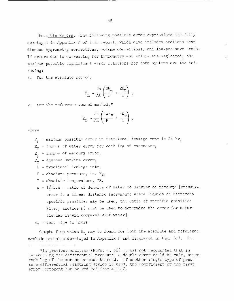
Possible Errors. The following possible error expressions are fully
developed in Appendix F of this report, which also includes sections that
discuss hygrometry corrections, volume corrections, and low-pressure tests.
If errors due to correcting for hygrometry and volume are neglected, the
maximum possible significant error fractions for both systems are the fol
lowing:
1. for the absolute method,
2. for the reference-vessel method,*
24 /4^EH 4ETNEL = At \~P + "t",
where
E = maximum possible error in fractional leakage rate in 24 hr,
E = inches of water error for each leg of manometer,H
E = inches of mercury error,
E = degrees Rankine error,
L = fractional leakage rate,
P = absolute pressure, in. Hg,
T = absolute temperature, °R,
U = 1/13.6 - ratio of density of water to density of mercury [pressure
error is a linear distance increment; where liquids of different
specific gravities may be used, the ratio of specific gravities
(i.e., another u) must be used to determine the error for a par
ticular liquid compared with water],
At = test time in hours.
Graphs from which ET may be found for both the absolute and reference
methods are also developed in Appendix F and displayed in Fig. 3.3. In
*In previous analyses (Refs. 1, 52) it was not recognized that indetermining the differential pressure, a double error could be made, sinceeach leg of the manometer must be read. If another single type of pressure differential measuring device is used, the coefficient of the firsterror component can be reduced from 4 to 2.
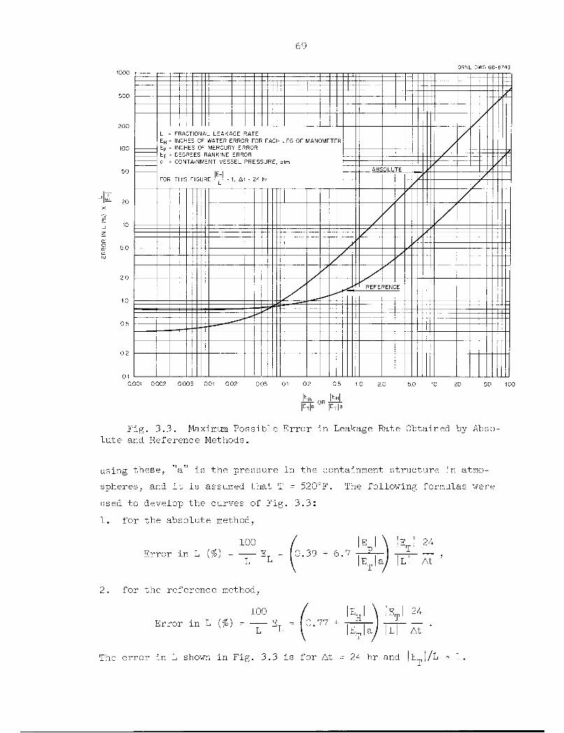
20
10
69
ORNL-DWG 68-8743
L = FRACTIONAL LEAKAGE RATE
EH = INCHES OF WATER ERROR FOR EACH LEG OF MANOMETEREp = INCHES OF MERCURY ERRORET = DEGREES RANKINE ERRORa = CONTAINMENT VESSEL PRESSURE, aim
NFOR THIS FIGURE ~ = 1, At = 24 hr
ABSOLUTE
' REFERENCE
0.001 0002 0005 001 002 005 0.1 0.2 0.5 10 2.0 5.0 10 20 50 100
N° °R N°
Fig. 3.3. Maximum Possible Error in Leakage Rate Obtained by Absolute and Reference Methods.
using these, "a" is the pressure in the containment structure in atmo
spheres, and it is assumed that T = 520°F. The following formulas were
used to develop the curves of Fig. 3.3:
1. for the absolute method,
100
Error in L (%) = EL L
2. for the reference method,
100
EJ 24I rp I0.39 + 6.7 -7—^
IE |a/ |L| At
The error in L shown in Fig. 3.3 is for At = 24 hr and |E |/L = 1.

To obtain error percentages for other values of At and |E |/L, values
from the curves must be multiplied by 24/At and by JE |/b. Figure 3.3
shows that for the same precision of linear measurements, the reference
method gives smaller error percentages in L for values of |E |/|E |a >
0.067, and larger error percentages for values of |E / Em a < 0.067.' to p T
As an example, let
L = 0.001 for 24 hr,
At = 12 hr,
E and E =0.1 in. Hg and H20, respectively,P H
ET = 0.1°R,
then
a = 2 atm,
|EJ |E I |EJ, , and , , =0.5 and —— = 100E a Em a LI rpl i Ti
The absolute method yields 3.74 X 100 X 2 = 748% error in L, and the ref
erence method yields 1.27 X 100 X 2 = 254% error in L. If the precision
of measuring the pressures were increased to 0.01 in., the errors in L for
the absolute and reference methods would be 145 and 164%, respectively.
Primary use of the possible error analysis is to determine before the
test the necessary precision of temperature and pressure measurements re
quired to keep the error a reasonable fraction of the leakage rate. If,
for example, it is desirable that the errors in leakage-rate determination
due to the errors in pressure and temperature readings are each always less
than 25% of the leakage rate (L), it is shown in the general development
in Appendix F that in a 24-hr test at 1-atm overpressure (a = 2) and a
test temperature of 530°R the precisions listed in Table 3.4 are required.
To obtain precision for other overpressures, multiply the pressure by a/2;
for other temperatures, multiply the temperature by T/530; for other de
sired fractions, multiply the values by 4(f); and for other test times,
multiply the values by At/24.
Probable Error. Error analyses of test results have generally fol
lowed two basic approaches: (l) correlation of instrument error and
(2) analysis of test results on a statistical or quasi-statistical basis.

71
Table 3.4. Minimum Precision Required in Leakage-Rate Tests
_owable
:akage
hr
E, Minimum Precision Required
L, Maximum A13Fractional Le
Absolute Method Reference Method
Rate in 24EP
Em EH Em
(in. Hg) (°R) (in. H20) (°R)
0.05 0.38 3.3 2.6 1.7
0.01 0.075 0.67 0.51 0.33
0.005 0.038 0.33 0.26 0.17
0.001 0.0075 0.067 0.051 0.033
0.0005 0.0038 0.033 0.026 0.017
0.0001 0.00075 0.0067 0.0051 0.0033
Instrument correlation has been accomplished in some instances by direct
summation of the individual instrument's limits of precision and in others
by application of the second-power error-propagation law. In neither
instance of instrument correlation is there a basis for estimating the
errors due to inadequate sampling and reading. Statistical or quasi-
statistical analyses vary from simple visual inspection of data compared
with some mean line to a sophisticated analysis; for example, regression
analysis. The reluctance to spend much time and money for analysis when
the data appear to be consistent is understandable. However, a statistical
analysis of the data may reveal inadequacies in reference volume design or
instrument distribution and precision. Robinson of ORNL has discussed some
of the problems with reduction of test data and error analysis.37>58>63
Any attempt to justify statistical methods to estimate leakage rates beyond
a reasonable and practical degree of accuracy becomes a moot point when
compared with the orders of magnitude of the related factors employed in
conjunction with the specified allowable leakage rate in the calculation
of concomitant radiological doses associated with fission-product losses
from the containment atmosphere.
A not uncommon experience in recording and analyzing leakage-rate
data is the obviously spurious result that inleakage is occurring rather
than outleakage. A presurvey of the temperature gradients is needed to

72
assure proper sampling and enable the operator to arrive at valid conclu
sions as to the location and number of temperature sensors required for
the test. Improper sampling is not the only possible cause of calculating
or observing inleakage. Other potential causes are leakage from com
pressed-gas or liquid systems within the containment, possible outgassing
from porous internal structures, or leakage from the reference system.
As pointed out in Section 3.5 of this report, consistent, mathema
tically sound error analyses have not been made for all leakage tests in
such a way as to determine the absolute accuracy of the test. Guidance
from the literature is offered,64 but there are several formulas available
and no clear indication of which is the best. One approach would be to
expand proposed standard ANS 7.60 to cover error analyses and supply such
guidance as can be synthesized from the best literature.
Error analyses, in one form or another, always form a basic part of
engineering measurements and should receive proper emphasis in planning
and interpreting leakage-rate tests. In general terms, a complete error
analysis should include the following features:
1. All measurement errors for instruments and test conditions should
be separately identified and a quantity given to each from good judgment
and best available sources, such as calculations from physics data tables,
vendor certification after extensive testing with traceable standards, etc.
2. "Accuracy" factors or factors that allow error to be reduced due
to the additional accuracies obtained by multiple measurements and data
handling by least-squares fit should be generated by using accepted error
analysis techniques.
3. Errors should be combined by using one form or another of the
error-propagation law. This has been the area most heavily covered in
the literature.
An analysis of this type will aid in providing reliable information
on required instrument accuracy and therefore will aid considerably in
instrument selection and place proper emphasis on the necessity, in some
cases, of multiple instrumentation and special data-handling techniques
to improve accuracy. A typical error analysis flow diagram is shown in
Fig. 3.4.

Individual
Measurement
Errors
Manometer
-resolution
-density-nonverticality-etc.
Absolute Pressure
-resolution
-density-barometric effects
-etc.
Temperature
-sampling
-resolution
-dead-band
-voltage regulation-nonlinearities
-etc.
Humidities
-sampling-resolution
-reproducibility-nonlinearities
-etc.
Other Instruments
Determine Magnitudes
(vendor certification,physics calculations,
order-of-magnitude
estimation)
o
o
o
o
o
ORNL DWG 68-8744
Analysis Procedure
Factor in "Accura,cy"Factors to Reduce
Errors (due toaveraging and least-
squares-fit processing)
Combine by Error Propaga.- Resultant
tion (observe data in- Absolutedependence, "one-sided" Error inerror, and non-Gaussian Lea.kagecurve considerations) Rate
Fig. 3.4. Error Analysis Flow Diagram.
-a

74
Based on good error control in running a leakage-rate test, the fol
lowing steps have generally been used in computing the leakage rate in
typical tests (see leakage-rate computation flow charts, Figs. 3.5 and
3.6):
1. Multiple measurements are weight averaged, and justification for
the weighting factors is provided; for example, five temperature sensors
in five separate cubicles are weighted by proportional cubicle volume.
2. Least-squares analyses are performed on the data. This technique
can only be applied when the data are known to be linear with time or can
be assumed to be linear for a short time. In leakage-rate tests this
generally means that a least-squares fit can usually be applied for a few
hours of temperature, humidity, or manometer points before and after the
data times. More sophisticated regression analyses, which are similar but
follow nonlinearities in the data better, can be used for longer times and
greater accuracy.
3. Leakage rates are then computed from the processed data.
4. Corrections are computed and factored into the result.
5. A classical error analysis is performed on the entire test unit,
including corrections. The basic features of such an analysis are given
above.
As is well known, absolute instrument accuracies are not a require
ment when parameter changes are utilized rather than absolute quantities.
The remaining types of errors, although similar, are much more significant.
Some of these, such as scale resolution and instrument dead band, are
easily identified and measured. Others, such as instrument nonlinearities
and containment sampling, are not. In most cases it will be important to
check instrument calibration by recent comparison with a standard that can
be traced to a national standard. In some cases, this may not be necessary
if absolute linearity is known and only parameter change is significant.
Sampling errors are difficult to determine accurately. While it is
possible to study the problem with detailed calculations, it is usually
sufficient to make an order-of-magnitude estimate of the maximum conceiv
able error from this source. Some help can be obtained by looking at the
mixing-time constant of the test, which is calculated from the amount of
air circulation provided, as aided, perhaps, by natural diffusion. If the

Raw Data
Manometer
Absolute Pressure
Temperatures
Humidities
Liner Temperature
Other Corrections
ORNL DWG 68-8745
Analysis Procedure
Weight Average Make Least-
Data Squares FitCompute Leakage
RateMake Corrections
Compute Final
Leakage Rate
Fig. 3.5. Leakage-Rate Computation Flow Chart.

Raw Data
Manometer
Absolute Pressure
Temperatures
Humidities
Liner Temperature
Other Corrections
Weight Average
Data
Analysis Procedure
Compute Leakage
RateMake Corrections
ORNL DWG 68-8746
Make Least- Compute Final
Squares Fit Leakage Rate
o o
Fig. 3.6. Alternate Leakage-Rate Computation Flow Chart,
-JOn

77
containment temperature change for a time equal to the mixing-time constant
is determined, the sampling error can be found by order-of-magnitude mathe
matics to be a small fraction of this change. This has the added benefit
of demonstrating how stable conditions must be within the containment ves
sel when taking measurements in order for a proper test to be run.
With respect to types of instruments, no general agreement has yet
been reached on the best types. For temperature, resistance detectors,
thermocouples, and thermistors are used. Linearity and reference junction
stability problems can make thermistors and thermocouples less accurate
than resistance detectors. For humidity, sophisticated dew-point instru
ments are most accurate but may have large sampling errors if cost pre
cludes the use of more than one instrument. Psychrometers and various
electric sensing devices are more adaptable to a multiple measurement sys
tem, but special precautions must be taken with ea.ch because of inherent
problems of foreign material and poisoning which, if present, void the
calibration. In any case, humidity measurements can be highly nonlinear,
and it is usually required that recent calibration be performed with stand
ard vapor-pressure liquid solutions available at little cost. Inclined
manometers and barometric-type mercury pressure sensors are the instruments
usually used for pressure measurements. When great accuracy is required,
more sophisticated forms of these instruments (i.e., micromanometers,
servomanometers, etc.) are employed.
A note on corrections must be mentioned; that is, it is difficult to
instrument properly to ascertain the need for some corrections. Such is
the case for containment thermal expansion, reference system leakage, air
ingrainment in concrete and entrainment in canal water, and reference
chamber temperature lag. As pointed out in Ref. 1 and confirmed by ob
servations of typical plants, these corrections can be large and can void
the test results. For instance, a temperature change of 10°F in a
2,000,000-ft3 containment vessel can change the internal volume by about
700 ft3. (The magnitude of the volume corrections due to temperature and
temperature changes is given in App. F.) It is mandatory therefore that
some consideration be given to corrections; for example, by some control
of test conditions followed by a calculation proving that this control was

78
sufficient to make the correction negligible or the error in determining
the correction negligible.
3.2.3 Bare-Vessel Leakage-Rate Tests
Bare-vessel leakage-rate testing usually refers to the testing per
formed immediately after the initial strength test. These tests are per
formed before all penetrations and other auxiliary equipment are Installed
in the vessel. The tests are usually conducted at design- or maximum-
accident pressure conditions and are primarily to show that the vessel
fabricator has fulfilled his contractual obligations. As experience is
gained, it may be possible to defer such tests and combine them with pre
operational tests, particularly since leakage-rate tests without penetra
tions are not particularly meaningful.
The primary value of the bare-vessel test is that faults or leaks
that may later be hidden are easily detected and repaired. As can be seen
in Table 3.2, the calculated leakage rates based on these test results
have usually been below the required rate. The minimum time required for
testing has been 24 hr, and many tests have taken three to four days, with
some substantially exceeding this time.
An article prepared by McGrath and Zick of Chicago Bridge & Iron65
describes the testing procedures used by this firm to conduct leakage-
rate tests, discusses single and dual reference system results, and pre
sents test results for seven reactor containment vessels they have built.
They conclude that no leaks have been found in radiographed or magnafluxed
weld seams and that most leaks have occurred in mechanical closures at
penetrations. The article states that a leakage-free reference system
is mandatory and that leakage less than 0.1% of the total contained air
in 24 hr at design pressure can be measured with reasonable accuracy.
Chicago Bridge & Iron has developed a reference system equipment instru
ment package and techniques that are considered to be proprietary. They
normally perform the bare-vessel leakage-rate test and then remove all
reference vessels and their equipment package.
Second-generation PWR and BWR plants have containment structure de
signs that incorporate thick concrete barriers. This should result in
more uniform temperature conditions during leakage-rate tests. Under

79
these conditions, the minimum 24-hr testing period may be an excessive
requirement.
3.2.4 Preoperational Tests
Preoperational leakage-rate tests, as the name implies, are conducted
just prior to reactor operation with all penetrations and auxiliary equip
ment installed. Table 3.2 shows the preoperational test pressures, al
lowable leakage rates, and measured leakage rates for most of the existing
power plants. The tabulated allowable leakage rates at maximum accident
conditions are those stated in the latest technical specifications, which
are part of the operating license issued to each reactor operator. Con
sistent terminology has not been used for all plant allowable leakage
rates.
The AEC Technical Safety Guide specifies that preoperational tests
be performed at the design- or maximum-accident condition pressure and at
a lower pressure or pressures that may be used for future retesting and/or
monitoring tests. Either the absolute or reference method may be used.
3.2.5 Periodic Retesting
Because of the importance of containment integrity in reducing the
hazards associated with a nuclear power plant and because of the possi
bility of deterioration of seals in the containment system over long
periods of time, it is necessary that periodic inspection and retesting
be performed to insure that containment integrity is being maintained.
It is generally agreed that retests for strength are not required unless
additions or modifications to the vessel are made.
The retesting schedule for each reactor plant is based on demonstrated
performance capability and not on a rigorous and uniform arbitrary schedule
for all containment vessels. The AEC Technical Safety Guide (Appendix B)
provides that schedules for retesting be set up according to an expanding
interval such that successful retesting in the "as-is" condition is given
credit by expanding the time interval to the next required test. Such a
retesting scheme gives considerable emphasis in the right direction; im
provement of actual performance capability is rewarded by reduction of
the number of tests required. This effects savings in both time and money.

80
Section 17, "Periodic Inspection and Testing," of the USA standard for
steel containment structures (N6.2-1965) contains provisions regarding
periodic inspection and retests.
A full-pressure strength or integrated leakage-rate test of a con
tainment vessel containing a completed plant is rather difficult and
dangerous to perform. Much of the shell surface is inaccessible, so it
cannot be properly inspected after a pressure test, and in many cases,
some instrumentation and equipment installed within the containment ves
sel of a completed plant might be damaged if subjected to high pressures.
All containment structures are now required to demonstrate initially their
ability to withstand the maximum calculated accident pressure. Such tests
may also be required during the containment service life if modifications
or revised conditions dictate the need to reverify the leaktightness.
The principal reasons for permitting reduced-pressure tests are
(1) a reduction of the pneumatic testing hazard, (2) the avoidance of
metal fatigue effects of multiple testing at higher test pressures, and
(3) a reduction of the time and cost for pressurization and depressuri-
zation of the containment structure. One problem encountered in conduct
ing such reduced-pressure tests is the selection of a test pressure level
from which prediction of leakage at peak pressure is supported by experi
ence. After retesting the vessel leakage rate at reduced pressure, the
leakage rate determined must be extrapolated to an equivalent leakage rate
at design or maximum accident pressure, as discussed in Section 3.2.1.2.
An additional limiting factor in retesting the vessel leakage rate
at reduced pressure Is the time required to conduct such a test. To
obtain sufficient accuracy, such tests often have to run over a period
of one or two days or more, during which time access to the vessel for
operation or for maintenance work is not permitted. For a commercially
operating power plant, this loss of time could impose a substantial eco
nomic penalty.
Both the absolute method and the reference-vessel method can be used
for reduced-pressure tests without modification, except that the testing
period may be longer to provide adequate sensitivity, and more temperature-
measuring instruments or reference vessels might be required (compared with

81
initial bare-vessel testing) to give adequate temperature compensation
and/or indication.
Some other methods may be more attractive for retesting than the
absolute or reference-vessel methods because of the pressure and acces
sibility limitations. In particular, the method of checking individual
penetrations has several advantages. This method allows these penetra
tions to be tested at full design pressure without pressurizing the entire
containment vessel. A high degree of accuracy can be achieved with this
method if all sources of leakage are known. This method can be used to
test leakage of these penetrations at any time without interrupting opera
tion or maintenance of the plant and can even be used for continuous moni
toring.
Table 3.5 lists the retest pressures, allowable leakage rates, and
measured leakage rates for some existing reactor plants. Retesting sched
ules have varied from 12 to 24 months and, as previously mentioned, each
plant retesting schedule is reviewed with DRL and established on an indi
vidual basis. Retesting pressure and frequency of testing are still areas
of considerable controversy, and there appear to be no absolute rules that
can be applied. The technical specifications of older reactor plants
(which usually have shorter retesting periods) are being reviewed in the
light of recently issued AEC criteria and regulations.
The retest pressures and schedule for new reactor plants have not
yet been established, since it is not necessary to do so before commencing
operation, and operators are thus able to defer fixing retest requirements
pending development of additional knowledge and experience in the field
of integrated leakage-rate testing. Provisions are made in the plant
design for testing at full design pressure; however, the actual test pres
sure and schedule are not established until the technical specifications
are prepared.
Another aspect of retesting of containment integrated leakage rates
that has not yet been defined is the question of what the retest require
ments for prestressed-concrete containment vessels will be. A related
issue is the question of what retesting of prestressing tendons, anchors,
etc., will be required for these vessels. These and similar questions

82
Table 3.5. Periodic Integrated Leakage-Rate Tests of Existing Containment Structures
Reactor
Big Rock Point
CVTR
Dresden 1
Elk River
Humboldt Bayf
Maximum Accident
Conditions
Pressure Leakage Rate
(psig) (vol %/2k hr)
20
19
29.5
21
0.5C
0.5
0.5
0.1
Retest 1^, AllowablePressure Retest
(psig) Leakage Rate3
10
13
20
11
0.121 at 10 psigd
0.5 at 21 psigc
0.294
0.l4
Periodic
Drywell 36 10 10 2.5
Suppression chamberContinuous
Drywell
25
36
10
10
10
0.72
2.5
Suppression chamber 25 10 0.36
Indian Point No. 1 24.2 1,,oc 25 and
1-2
1.0°
Oyster Creek 33 0,.5 15 0.5
Pathfinder 78 0,.2 50
78
0.11
0.14
San Onofre 46.4 0.5
Shippingport 59 0.15
Yankee 3^.5 0.1
23.2
10
23
1.5
0.26
0.065
0.7
Not defined
L0, AllowableOperational
Leakage Rate°
Not defined
Not defined
Not defined
0.106a
1.25c
1.25c
0.29c
0.l4c
0.1a
0.08a0.11a
0.20a
Not defined
0.5a
aLeakage rates given in units of %of free air volume per 24 hr; tests performed with air atambient temperature.
bL0 = ^ (hnn/hn)> where Lmn is the averaged continuous leak rate prior to the last Class Atest and L^ is the measured leak rate of the last Class A test.
cWeight percent of contained atmosphere per day.Corrected to test pressure by Lfc = Le[(Ff - l)/(P| - D] (ne/k*) , *here ^ = leakage rate at
test pressure, Le = leakage rate at extrapolated pressure, Pe = test pressure in atm abs, Pe = extrapolated pressure in atm abs, ne = viscosity of air-steam mixture at test conditions, m^ =viscosity of air at test conditions.
Range ofLeakage RatesBeing Measured
0.021-0.077
O.OO6-O.O86
0.088-0.184(±1.4$)
0.039-0.09
0.04-0.36
0.18-0.61
0.05-0.02
0.03-0.05
0.012
0.04-0.08 at78 psig
0.055
<0.065
0.007-0.012
Controlled
Leak
Required
Yes
No
Yes
Yes
Yes
No
Yes
Yes
(h)
Yes
No
Yes
Effective
Date
9/66
8/66
12/61
3/67
Status Test Method
Technical Reference
specifications
Technical Reference
specifications
Technical Reference
specifications
Tentative Reference
Current Tentative Reference
5/65 Tentative
1/5/66 Technicalspecifications
Absolute and
makeup
Reference
Required Retest Schedule
24 months unless Lt exceeds limit; if so,12 months
Once prior to January 1967, augmented bycontinuous 2-psig test
12, 24, and 36 months;e also all tentativeinformation and the entire question oftesting, including pressure, frequency, andequipment, are currently being reviewed
12, 36, and 60 months; thereafter6 one-yearintervals until AEC approves change
Continuous8
12, 24, and 48 months at 25 psig;d thereafter continuous at 1 to 2 psigS
12/65 Technical Reference 12, 24, and 24 months thereafterespecifications
3/67 Technical Reference 24, 26, 39, and 39 months thereafter6specifications
5/65 Technical Reference At each seed refueling of core 2; about 24specifications months
Current Tentative
Current Tentative
48 months; 12 and 25 months if Lt exceedslimit
Absolute Continuous8
SRestart at most frequent interval if L^ too high,
fHumboldt Bay proposed operational leakage-rate requirements are higher than the initialcontainment design specifications.
Continuous leakage-rate checking is employed.
hPump-back of air into containment structure through calibrated meter to verify themeasuring technique.
jS^sai/'iSri***-

83
are being faced by industry and the AEC in connection with the licensing
of plants such as Brookwood, Turkey Point, and Palisades. In view of
the extensive use of prestressed structures being proposed, the answers
to these questions will have an important effect on the nuclear power in
dustry. The industry is faced with a difficult task in view of the lim
ited experience with prestressed-concrete structures in the U.S. to date.
3.2.6 Continuous Integrated Leakage-Rate Testing
A continuous integrated leakage-rate monitoring system can be used
to measure the leakage of a containment structure during periods when
containment leaktightness is essential. The system operates by maintain
ing the containment structure under a pressurized (or vacuum) condition
with relation to ambient atmospheric conditions and includes provisions
and instrumentation for continuous or periodic determination of the leak
age rate of the structure.
Systems of this type are very desirable because they enable a re
actor plant operator to keep a check on the continuing integrity of the
containment system rather than having to rely on a periodic checkup, be
fore which the system, might have been operating with a hatch inadvertently
left open, for example. However, leakage-rate results obtained for these
low-pressure systems must be extrapolated to the test pressure conditions
indicated in the plant technical specifications, and the method of extrapo
lation must be verified by periodic leakage-rate tests at the higher test
pressure. Because of the difficulties of scaling the leakage rate with
pressure, this method may not give a true measure of the leakage rate at
design or accident pressure; however, it does provide an excellent check
to assure that all openings are closed and that some minimum degree of
containment integrity is being maintained.
Systems of this type are discussed in the AEC Technical Safety Guide
(App. B) which sets the desirable average containment operating pressure
at not less than 10% of the retest (P ) pressure, which is normally set
at a minimum of 50% of the design pressure (P ). The 10% value appears
to have been arbitrarily set and has not gained general acceptance in
the industry.

84
Existing reactor plants that are now using continuous low-pressure
leakage-rate monitoring systems are Yankee, Humboldt Bay, Indian Point
No. 1, and CVTR. The operators of these plants are enthusiastic about
this method of monitoring containment integrity. The operators of
Dresden 2, which is a new BWR, are considering using a low-pressure con
tinuous-monitoring system, as are the operators of Connecticut Yankee
at Haddam Neck, a new PWR.
A method similar to the makeup-air method is used at the Yankee
Nuclear Power Station, both as a check on periodic reference-vessel test
ing and for continuous monitoring of the leakage rate during plant opera
tion. During operation, a nominal internal containment pressure of 1 psig
is maintained. Leakage from the containment area is determined by re
charging to the Initial system pressure with a measured amount of air.
Recharging is done at intervals not exceeding 60 days and the containment
pressure is recorded every other hour. Pressure, temperature, and humidity
are recorded daily. Yankee reports that a gross leak can be detected in
less than a day, and very small leaks can be detected within a month.
This provides a semicontinuous verification of vapor-container integrity
that would be impractical if reliance were placed on periodic high-pressure
tests. Leakage rates as low as 0.01% In 24 hr are said to be detectable
and measurable within a month and larger leaks in a much shorter time.
This system has been very useful in detecting leakage from faulty gaskets
and other types of improper closure. In order to satisfy the intent of
the AEC Technical Safety Guide, which, as mentioned above, specifies that
the continuous test pressure must be 10% of the retest pressure, Yankee
has now increased the continuous internal pressure from 1 to 1.5 psig.
Humboldt Bay has a dual pump-back system to provide a measure of
containment integrity. In this plant, the drywell and suppression chamber
are pressurized to 0.72 and 0.36 psig, respectively. Periodically the
drywell and suppression chamber are repressurized, the amount of air charge
is measured, and an apparent leakage rate Is determined for each vessel
(see Table 3.5 for measured leakage rates reported for Humboldt Bay).
The CVTR In-Plant Testing Program, includes an evaluation of continu
ous leakage-rate testing methods; however, recent programmatic changes
85
may limit this phase of the work. Continuous leakage-rate tests are
conducted at the CVTR during reactor operation. Leakage rate is measured
by the reference-vessel method at an overpressure of approximately 2 psig.
Measured quantities of makeup air maintain the 2-psig overpressure and
provide an additional check on the leakage rate. Specific details of
this phase of the CVTR test program are included in Appendix G of this
report.
A negative-pressure continuous leakage-rate testing system is to be
used at the Surry Station of the Virginia Electric Power Company.67 Ref
erence-volume types of pressure-determination systems are to be used that
have an accuracy to determine less than 0.1% leakage in 24 hr at 10 ± 0.5
psia. The Molten Salt Reactor Experiment at ORNL is another example of a
plant with a negative-pressure (-2 psig) continuous monitoring system.68
3.2.7 Conventional Building Tests
Structures similar to conventional buildings are used for reactor
containment if a reactor accident would not produce a substantial pressure
rise and a high degree of leaktightness is not required. Structures of
this type are often operated at reduced pressure, and leakage from the
building is prevented by maintaining a ventilation-system flow rate suf
ficient to produce a slightly negative pressure within the building so
that all leakage is inward. The ventilation exhaust is usually directed
up a stack, with provision for filtering. For buildings operated in this
way, it may be that the only leaktightness requirement is that the spe
cified reduced pressure be maintained with a given ventilation blower
capacity. In this case, a leakage test would consist only of measuring
the differential pressure of the building with a water manometer while
the ventilation system was operating.
If a maximum leakage rate is specified for the building, in addition
to a reduced pressure, a leakage-rate test can be performed by measuring
the flow rates of the ventilation system intake and exhaust with conven
tional gas flowmeters. The leakage rate is then the difference between
these two flow rates. This is a convenient and simple means of deter
mining the leakage rate with reasonable accuracy, since all leakage is
channeled in one flow path.

Leakage rates of conventional buildings are usually large enough —
from 100% per day to 100% per hour or more — to be measured in this way
without special techniques or long test periods. If special provisions
are taken to minimize leakage, such as using special doors, joints, seals,
coatings, etc., leakage rates as low as a few percent per day may be
achievable.69'70 In this case, it may be necessary to use more sensitive
devices to measure the leakage rate. However, if the building is to be
operated at reduced pressure, the same general procedure of measuring the
ventilation system flow rate is usually used. If the building is designed
for a slight positive pressure and a maximum allowable leakage rate is
specified, one of the pressure-decay leakage-rate testing methods can be
used.
3.2.8 Multiple-Barrier Containment Tests
An example of the multiple-barrier containment concept i& the Malibu
plant proposed by the Los Angeles Department of Water and Power.7 Two
steel membranes with porous popcorn concrete between them form an airtight
space, which is maintained as a negative-pressure zone. The negative-
pressure zone is continued throughout the floor of the containment vessel,
and all penetrations are interconnected to the same zone. A pump-back
subsystem is provided to maintain the negative-pressure zone and capture
any outleakage through the inner membrane or inleakage through the outer
membrane. Three 10-cfm pump-back compressors discharge to the space in
side the containment structure. All compressors are located outside the
containment structure where they are accessible for maintenance.
After the inner and outer steel membranes and the popcorn-concrete
fill have been completed the space between the membranes is charged with
a Freon gas—air mixture at 2 psig. All membrane welds are then traced
with a halogen gas leakage detector, and all defects are repaired and
rechecked. The outer reinforced-concrete wall is then poured, and the
strength test is performed.
A two-step leakage-rate test is then conducted. The inner membrane
is tested with the popcorn-concrete zone vented to the atmosphere and the
containment system pressurized. The reference vessel method is used for

87
both tests, which must show independent leakage rates less than 0.1% by
volume in 24 hr at 15 psig. As a check, the internal pressure is restored
to its original value when the original temperature is reestablished, and
the air required to do so is measured by a positive-displacement gas meter.
During normal plant operation the containment system integrity de
pends on the reliable operation of the compressors and the leaktightness
of the pump-back subsystem itself. A leak-detection system, consisting
of two air meters and a remote-reading absolute-pressure measuring device,
is used to measure the amount of leakage through the membranes into the
negative-pressure zone. Three air meters are so located that it is pos
sible to determine which membrane is leaking. Leakage through the inner
membrane is located by pressurizing the annulus with a Freon gas—air
mixture and tracing the inside surfaces with a halogen gas leak detector.
Leakage through the outer membrane presents a more complex problem, since
the membrane is covered on the annulus side by popcorn concrete and the
other by reinforced concrete. The method chosen is to install l/4-in.-0D copper tubing adjacent to the membrane wall in contact with the pop
corn concrete. All the tubes are installed vertically, spaced on 10-ft
centers, and brought together a,t the top of the containment structure into
a header. Within each vertical channel the tubes terminate at elevation
intervals of 10 ft so that the open lower ends of all tubes are spaced
10 ft apart horizontally and vertically. To locate a leak the annulus
is purged of air by introducing inert gas at the top of the vessel and
exhausting at the bottom with the pump-back compressors. A slight nega
tive pressure is maintained and each of the tubes is uncapped and con
nected to a small vacuum pump and oxygen analyzer. By locating the tube
with the highest oxygen content the leak can be located within an area
10 ft square. Once the leak is located it is necessary to chip away the
reinforced 50-in.-thick concrete wall, locate the exact leakage site, and
effect repairs. Over 17 miles of copper tubing is required for this
system.
An attempt should be made to develop a simpler and more effective
method of leak location.

3.3 Leakage Surveillance Testing
This section discusses leakage surveillance testing in the broadest
sense, including a brief discussion of local leak testing experience and
techniques, as well as the various methods of testing for leakage where
leakage is most likely to occur at containment penetrations. Testing of
isolation valves is also covered in this section.
3.3.1 Local Leak Testing
Local leak tests are performed to detect and locate leaks in the
containment vessel shell, penetrations, or other containment components
so that they may be repaired. A number of local leakage-testing techniques
are listed in Tables 3.6 and 3.7. Local leak tests may be performed in
conjunction with an integrated leakage-rate test of the entire contain
ment system or by pressurizing a component such as a penetration, air lock,
or isolation valve. These local tests, although often very sensitive,
have been used principally as a qualitative indication of leakage. Usu
ally, no attempt has been made to measure the rate of leakage out of the
leaks detected, and since the tests are usually performed over a limited
area, there is no positive assurance that all leaks have been detected.
However, some success has been achieved with correlating the total of
individual local leakage rates with the results of an integrated leakage
test.
Local leak tests can be performed on various containment components
before they are installed in the vessel, as well as on individual com
ponents after the vessel has been completed. Information concerning the
approximate sensitivity of various local testing techniques, with rather
ideal test conditions assumed, is included in Table 3.6. The soap-bubble
test is by far the most generally used method of local leak testing. Spe
cific information on each method shown in Table 3.6 is discussed in Chapter
10 of Ref. 1.
Additional information on local leak-testing procedures is included
as Appendix A of ANS 7.60, Proposed Standard for Leakage-Rate Testing of
Containment Structures for Nuclear Reactors (Appendix C of the report).
The applicability of local leakage testing is discussed, as well as water

Table 3.6. Order of Magnitude Sensitivity of Various Local Leak-Testing Techniques'1
Technique
Bubble-observation tests
Soap-bubble testWater-submersion test
Vacuum test
Sonic tests
Adulterant gas tests
Air-ammonia test with HC1 solution or
phenolpthalein indicatorHalogen gas sniffer test
Helium mass-spectrometer test
Radioactive gas test
Olfactory test
'Vrom Ref. 1.
Typical FlowDetectable Under
Specified Conditions(ft3/day)
10
0.01
0.1
15
1
10"3
10"6
10
1
Basis of Indicated Value
Observation of 2-in.-diam bubbles forming in <+ secObservation of 1/16-in.-diam bubbles at one persecond
10-ft3 chamber; 1/2-hr test; constant temperature;pressure readable to 0.1 mm Hg
Ammonia concentration of 10~3 parts by volume
Instrument sensitivity of 1 X 10"5 cc/sec; halogenconcentration on pressurized side of 10~2 partsby volume; all leakage ducted to instrument with
no external dilution
Mass-spectrometer sensitivity of 5 X 10 cc/sec;pure helium on pressurized side; all leakageducted to the spectrometer with no external di
lution
10-ft3 chamber; 330 nc 85Kr (l mr/hr at 1 ft, unshielded)
Average human sensitivity to mercaptan = 4 X 10~8parts by volume; local test mercaptan cencentra-tion of 10~3 parts by volume
CO

90
Table 3.7. Leak-Testing Methods and Order
of Magnitude Sensitivity3-
Minimum Detectable
Method Leakage
^torr-liters/sec)
Air test 1
Hydrostatic test 5 X 10"1Isotope test 7 x 10"2Fluorescence test 1 X 10~2Immersion test 1 x 10"
Soap-bubble test 1 X 10"3Chemical test 8 X 10"AHalogen sniffer test ~10"6Helium sniffer test ~10"8Mass-spectrometer envelope test ~10~
^rom Ref. 71.
submersion, vacuum, air-ammonia, halogen sniffer, and ultrasonic leak de
tector tests. A listing and descriptions of 19 leak-detection methods
and their approximate sensitivities are presented in a report by Cadwell.
Based on discussions with reactor plant operators, it is concluded
that local leak testing will continue to be used as a method of locating
leaks for repair that have been detected by pressure-decay tests. It is
considered unlikely that the technique of summing local leak-test results
to obtain an estimate of integrated containment leakage will ever be ap
plied to any appreciable extent.
3.3.2 Penetration Testing
Since it is generally accepted that penetrations through the contain
ment structure are the most likely location for leaks, there has been in
creasing attention given to developing means of testing penetrations to
increase the operator's assurance that allowable integrated leakage rates
will not be exceeded. This work has included development of techniques
for monitoring the leakage from groups of penetrations, as well as from
individual penetrations. The importance accorded these tests is evidenced
by the requirements for their frequent performance found in most reactor

91
plant technical specifications, as well as in Part III of the AEC Tech
nical Safety Guide (App. B). The frequent performance of penetration
tests has a compensating effect of allowing less frequent performance of
the more difficult and time-consuming integrated leakage-rate tests. The
Technical Safety Guide requires that penetrations be tested twice between
integrated leakage-rate tests and at least once per year.
Penetration testing may be conducted periodically or continuously,
and both methods are being used. The determination of the method to be
used is a complex and somewhat arbitrary process, since the other reactor
plant safety features must be considered, as well as the particular leak-
tightness assurance desired for the plant. In many reactor plants, no
specific provision is made in the penetration designs for penetration
testing. In other plants, this aspect of the plant design has been given
much emphasis. An example of an extreme case is Consolidated Edison's
Indian Point No. 2 Plant, where all penetrations can be continuously
leakage tested at full design pressure. In addition, provision has even
been made in this plant for continuous leakage testing of the containment
liner weld seams at full design pressure. Similar systems are being con
templated for other new PWR plants, although the method of utilizing the
system may be limited to partial initial testing or possibly periodic
testing.
The virtue of enclosing penetrations with small, monitored, pres
surized volumes is that 1 ft3 of leakage out of a 10-ft3 volume is much
more readily measured than 1000 ft3 out of a 2,000,000-ft3 volume. The
integrated leakage of all parts should be checked against the criterion
governing the leakage from the whole.
In discussing penetrations, it is important to recognize that there
are a number of different types of penetrations that vary in their indi
vidual probability of leaking. Penetrations can be broken down into the
following categories, which are listed in the order of decreasing tendency
to cause leakage:
1. personnel access and equipment hatches or air locks,
2. electrical and other penetrations that utilize gaskets, sealing
compounds, or other seals subject to possible deterioration with
time,

92
3. hot pipe penetrations that must accommodate pipe thermal expansion,
4. cold pipe penetrations.
Penetration-testing provisions for a number of representative re
actor plants are listed in Table 3.8, and each of the above penetration
categories is discussed briefly below. It should be borne in mind that
penetration design is currently of great interest to reactor plant de
signers, operators, and regulatory agencies, and this discussion of cur
rent practice in the field may be outdated within a few months. For this
reason, possible directions of change are also briefly mentioned in the
discussion.
1. Personnel Access and Equipment Hatches or Air Locks. Personnel
access and equipment hatches not provided with air locks are usually pro
vided with double gaskets to allow pressurizing between the gaskets in
order to check leaktightness, usually at full accident pressure. Actually
this type of test evaluates the leaktightness of only one of the two gas
kets in the proper direction, but this deficiency is considered minor.
Such a test can be performed either periodically or continuously, depend
ing on a specific design or the needs of the operator.
Personnel access or equipment air locks can be leak tested by pres
surizing the air-lock space between the two doors and either monitoring
pressure decay or using local leak-testing techniques. If the air lock
is used during operation, such a test could obviously not be easily per
formed continuously. For this reason, and for general testing convenience,
some air locks are being designed and operated with double gasketing to
allow leak testing as described above.
The design of a hatch or air lock should be such that pressure load
ing of the entire component, as in an accident, would not tend to adversely
affect its sealing capability. If this is not the case, pressurizing be
tween pairs of gaskets would not be a meaningful test. If these conditions
can be met, it is concluded that this method of testing major containment
access openings can be considered to be accepted practice. The only re
maining issue will be to establish the frequency of periodic testing or
the potential need for continuous testing interrupted only by access re
quirements for specific plants.

Reactor
Browns Ferry
Connecticut Yankee(Haddam Neck)
Dresden 2 and 3
93
Containment Spray System
1, 2, 3
1; system is interconnectedwith a normally operatingresidual-heat-removal system
1, 2, 3
Indian Point No. 2 1, 212 3Oconee x' ' J
Turkey Point 3 and k 1Key
1.
3.
Recirculation line providedfor periodic pump operationand flow testProvisions made for periodic air-flow testing ofvalves and nozzlesProvisions made for cyclingvalves dry
Tatole 3.8. Containment Engineered Safety Features and Penetration Testing Requirements for N*w Plants
Key to numbers in column listed at foot of column
Air-Recirculation and-Cooling System
Not used as engineeredsafety feature
Not used as engineeredsafety feature
1
1
1
Key:1. Fan motors designed to
operate at accidentconditions; periodictests consist of fanmotor start-stopcycles
Other Containment Heat-
Removal SystemsIsolation Valves
Personnel and
Equipment Hatches
Pressure-suppression-pool 1, 2 (reactor system valves) 1, 2 (personnel lock)cooling system has provisions for flow and
valve operability tests
Not available No information 1 and 3 (equipment hatch);2 (personnel lock)
Full-flow recirculation
testing
Not available
Not available
Not available
1 2 (reactor system valves) 1, 2 (personnel lock)
No information
No information
Key:1. Single tap between valves
for pressure-decay tests2. Double tap — one down
stream of second valve
for hydro test of fluidcollection
3 . Seal water systemattached to lines
1, 3, k1, 2 (personnel lock)
1, 2 (personnel lock)
Key: Key:1. Double-gasket ed seals withl.
pressure tapsDouble door or hatch with 2.provision for air-testingcavity 3.Weld test channels h.Continuous pressurizationsystem
2.
Electrical Penetrations
1, 2, 3
1; 2, 3, k
1
1
Test tap for air-testingpenetration cavityDouble-gasketed sealswith pressure tapWeld test channelsContinuous pressurization system
Hot Pipe Penetrations
2, 3, h-
None (no bellows)
None (no bellows)
Key:
k.
External channel surrounding bellowsWeld test channelsInternal sealed cavitywith test penetrations forair-testing bellows andwelds
Continuous pressurizationsystem
Cold Pipe Penetrations
None
None
None
1, 2, 3
None
None
Key:
Weld-test channelInternal sealed cavitywith test penetrationContinuous pressuriza-t ion syst em

94
2. Electrical Penetrations. Most designs of electrical penetrations
(and a few pipe penetrations in some plants) specify sealing compounds
and/or gaskets that are possibly subject to deterioration with time in a
reactor plant environment. Although in many early reactor plant designs
such penetrations were not made to be tested for leaks, it is considered
general practice today to do so (see Table 3.8). This is found to be the
case even in plants in which provisions for testing other penetrations
have not been made. Examples of typical electrical penetrations that can
be tested for leaks are shown in Fig. 3.7 (Ref. 50). A number of other
typical electrical penetration designs are shown in Chapter 9 of Ref. 1.
Electrical penetrations that can be tested have become standardized to
the point that manufacturers are offering standard electrical-penetration
prefabricated components.* It is anticipated that this trend will con
tinue and possibly extend to other types of penetration.
3. Hot-Pipe Penetrations. Hot-pipe penetrations include those
through which hot water and steam pass into and out of the containment
system. In many cases these penetrations incorporate a bellows or some
other means to accommodate pipe movement as a result of thermal expansion.
Current practice relative to the provisions made in the design of these
hot-pipe penetrations is not uniform. In some plants, such as Consolidated
Edison's Indian Point No. 2, hot-pipe penetrations cannot only be tested,
but they can be tested continuously at full design pressure, as shown in
Fig. 3.7. In other plants, such as Dresden 2 and 3, these penetrations can
be tested for leaks but only when the reactor plant is shut down and the
operator has access to the inside of the penetration in the drywell so that
a temporary test seal can be installed. This type of penetration is shown
in Fig. 3.8 (Ref. 73). Similarly, the Turkey Point hot-pipe penetrations
do not have builtin provisions for leak testing independently of the con
tainment system. It is emphasized that such differences in provisions made
for testing of penetrations result from the use of different containment
design concepts (pressure containment and pressure-suppression contain
ment), as well as differences in siting, reactor operator performance,
•^General Electric Company, San Jose, California, and Crouse-HindsCompany, Syracuse, New York.

SE4kL.WE.1_D
PRESSURIZING
CONNECTION
INSULATION(WHEN REQ'D)
PIPE
BEL.LOWS
\5EALWELO ff^k
PRESSURIZING.
CONNECTION
PIPES
95
PIPE SLEEVE
CONTAINMENTLINER
PRESSURISING.
CONNECTION
END PLATE
PIPE 5LEEVE
PIPING PENETRATIONCOLD PIPEL
PCE5SURIZING
PRESSURIZINGCONNECTION
tf%CONNECTION
END FLAN&3
EXHAUST PIPEAND VALVE
IB^. -— -»y . • I i I Ir, , i , I • • • i i • i i i i i i ' ' i i t ii l l I^ III-l-L^
i> I > I I r I 1 I ' • I I > ' > > ' ' > I I I I I I I ' I/ , , i , , , >, i i i r ii ii r ,- r i / j^y i i r^\ f.,,,,,,, i j> , >, i i i i i f , , >,',7^*' ' sSN l~
PIPE
SEALWELD
BELLOW6
XJP XPIPE„ SLEEVE
PIPING PENETRATIONPURGE piping "
CONTAINMENTLINER
PRESSURIZINGCONNECTION
STRAPANCHOR
CARTR1D6E FLANGE
PRESSURIZINGTSfi-eT
TRU-SEAL NUT
SLAND FITTING
SOUD COPPER ROD
t. jW-r-r-i i i I I i > I i I I I I I I I I • > > i I J > • i > r I I I I 1-7-7 INSULATED CABLE
CABLE GLAND FITTING
O-RINS
CARTRIDGEEND PLATE
PRESSURIZINGCONNECTION
SEALWELD
PRESSURIZINGCONNECTION
ELECTRICAL. PENETRATION
STRAIGHT THROUGH CONDUCTOR
III ' ' '••••**'•>>••• 'I I r-r-i
TREAT PLUG t. JACK CABLECONNECTOR FOR BFCA5LEWITH EPO%Y RESIN TO PROVIDEAM EFFECTIVE STOP JOINT. iy .
CARTRIDGE FLANGE
"re?
PRESSURIZING
INLET
TRU-SEAL NUT
GLAND FITTING
RF CA&LE
-O- RING
AIR AND TESTCONNECTION
^CONTAINMENTLINER
ELECTRICAL PENETRATIONJOINTED CONDUCTOR
Fig. 3.7. Typical Containment Penetrations. (From Ref. 50,

DRYWELL SHELL (INTERIORS
DRYWELL SHELL TO
PENETRATION SLEEVE
JOINT
CONTINUOUS RING FOR
SEAL SEAT
©
I
ISOLATION-
VALVE
96
DRYWELL PENETRATION SLEEVE
TEST TAP
GUARD PIPE.
BELLOWS EXP. JOINT
-MULTIPLE FLUED HEAD FITTINGS
•A) &. @(F1ilfc^•".. ^ V 'V V V V ^ V\T jr-y
\l/ /
z.-=£P\
LINE INSULATION
-CLEARANCE
* PIPE SUPPORTS, STOPS AND GUIDES-ALLOW NORMAL PIPE LINE GROWTHAMD MOVEMENT IN PENETRATION
PARALLEL TO PENETRATION ONLY.
Fig. 3.8. Typical B"WR Steam Line Penetration. (From Ref. 73 \
L-ISOLATIONVALVE

97
reactor plant designer philosophy, and AEC demands. Despite these dif
ferences, it is probable that a more standardized approach to the design
of provisions for testing hot-pipe penetrations will be developed in the
future.
4. Cold-Pipe Penetrations. Cold-pipe penetrations are those through
which cold water or air pass through the containment barrier. In most
cases no specific provisions for leak testing of these penetrations are
made in containment designs. Only in the most extreme cases, where even
the containment weld seams are tested, is consideration being given to
either continuous or periodic testing of cold-pipe penetrations. If proper
attention is given to the design, fabrication, and quality control of such
penetrations, it appears that, except in very rare instances, leak testing
of such penetrations will not be required.
3.3.3 Weld-Seam Testing
In some recent PWR plant designs, channels have been welded over seams
in the reactor containment vessel liner to allow leak testing of the seams.
The particular methods of utilizing these weld-seam testing channels vary
from plant to plant, and a consistent pattern has not yet developed. For
some plants, notably Consolidated Edison's Indian Point No. 2 plant, the
reactor operator has been committed in negotiations with the Atomic Energy
Commission to continuously test the weld seams at full design pressure.
In other plants, such as Turkey Point, the weld seams will be tested
initially by using the channel, but integrated leakage-rate testing will
be relied upon to detect any subsequent leakage. In utilizing weld-seam
leak-testing channels it should be recognized that the operator is test
ing not only the weld that forms part of the containment barrier but also
two additional welds required to seal the testing channel around the weld
seam. It is considered that if leakage did occur it would have at least
as high a probability of occurring through these channel welds as through
the containment liner welds. As a result, the reactor operator might be
led by an indication of a weld-seam leak to shut down the reactor plant
and break out concrete in order to find the indicated leak, only to dis
cover that the leak was in the testing system itself and not in the liner
weld seam being tested. It appears that a more realistic approach would

be to combine stringent quality control of the liner weld seam with con
tinuous and/or periodic leak testing of the containment in lieu of con
tinuous high-pressure testing of weld seams with installed test channels.
3.3.4 Isolation-Valve Testing
The openings in containment structures caused by piping penetrations
must be controlled in order to avoid violation of containment integrity
and thus nullify the intensive work done on penetration and containment
design and testing. Although some of these openings are normally closed,
many must remain open or be opened occasionally if the reactor is to op
erate and produce power. These openings are often separated from both
the reactor coolant system and the containment atmosphere by at least one
solid metallic barrier, such as a heat exchanger shell or tube walls that
also must fail if radioactive material is to be released to the piping
penetration. Because of these factors, normally opened or occasionally
opened piping penetrations are allowed, provided they are equipped with
the appropriate isolation valves. The number and types of isolation
valves used, the leaktightness specified, and the closure speeds required
depend upon the amount and type of radioactive material potentially
available to the fluid being transmitted, the time dependency of this
source entering the fluid, the transport characteristics of the fluid,
the degree of containment of the fluid and its contained radioactive mate
rial in any secondary confinement system, and the consequence of failure
of or leakage through an isolation valve under accident conditions.
Because of the different radioactive material sources and fluid
transfer characteristics associated with each type of reactor plant design,
the isolation-valve requirements must be evaluated for each specific ap
plication. However, although exceptions do exist, the following criteria,
discussed in Chapter 9 of Ref. 1, represent the practice that has usually
been followed with respect to the number and location of isolation valves
used in piping that penetrates the containment boundary in a water-cooled
reactor plant. The following criteria are not necessarily representative
of current practice for all plants.

99
1. Lines that are normally closed need only a single isolation
valve. A lock or seal or interlock should be provided if this valve is
remotely actuated to prevent it from being opened during reactor operation
or during otherwise potentially hazardous situations. Even though nor
mally closed, lines routinely containing very highly radioactive fluids
or which are open to the containment system are often equipped with mul
tiple valves to guard against accidental opening and to provide greater
assurance of leaktightness.
2. Lines that connect to the primary coolant system and are normally
open or occasionally open are usually provided with two isolation valves.
For incoming lines (e.g., lines for makeup, feedwater, emergency cooling,
control rod cooling), one or both may be a check valve. The valves should
be located so that one is inside and one outside the containment barrier.
At least one should close automatically to prevent flow reversal. For
outgoing lines (main steam lines in direct-cycle plants and lines for
purification system and emergency cooling), one valve is also usually
placed on each side of the containment wall. At least one of these valves
should close automatically upon receipt of a signal indicating a system
failure. On the Humboldt Bay plant, two tandem isolation valves are lo
cated on the main steam line just outside the drywell, but a guard pipe
extends the drywell barrier to the first valve and thereby in effect
makes one valve body part of the wall and one valve external to the wall.
3. Lines that are open to the containment system (e.g., lines in
ventilation and purging systems and containment spray systems) are nor
mally provided with two valves in series. At least one should close auto
matically upon indication of a system failure. Ventilation system valves,
which may be somewhat less positive in closing because of their greater
dimensions, often are both automatically closed at the same time. (This
discussion also applies to purge-line valves that are normally closed
during reactor operation.)
Ventilation system valves have been a source of potential contain
ment leakage in many existing plants, such as Shippingport7,4 and ElkRiver.2U It is extremely difficult to maintain leaktightness in such
large valves that require periodic actuation. Partly as a result of this
experience, open ventilation systems are not being used in any new plants.

100
Instead closed air recirculation and cooling systems that utilize cooling
water which passes through the containment barrier are being used, and
normally closed purge-line ducts are included to allow purging of the
containment system prior to an extended shutdown, such as for refueling.
^- For lines that connect closed-loop systems in the containment
system, no generalizations are possible. Since by definition these pene
trations are separated from the containment atmosphere and the primary
system by a continuous barrier, such as the pipe wall, heat-exchanger
tubing or casing, pump wall, etc., the need for further protection pro
vided by an isolation valve is dependent on the vulnerability of the in
terior barrier to failure, the direction of flow likely upon failure, and
the radioactive material transport likely upon failure.
The following discussion abstrated from Amendment 2 of the Dresden
Nuclear Power Station Unit 2, Plant Design and Analysis Report,33 gives
an example of application of the above criteria:
"The test capabilities which will be incorporated in theprimary containment system to permit leakage detection testing of containment isolation valves are separated into twocategories.
"The first category consisting of those pipelines whichopen into the containment and do not terminate in closedloops outside the containment will contain two isolationvalves in series. Test taps are provided between the twovalves which permit leakage monitoring of the first valvewhen the containment is pressurized. The test tap can alsobe used to pressurize between the two valves to permit leakagetesting of both valves simultaneously. The valves, associatedcomponents, and equipment which will be subjected to containment pressures during the periodic leakage tests will be designed to withstand containment design pressure without failureor loss of functional performance. The functional performanceof these devices will be verified by demonstration either during a leakage test or subsequent to the test but prior to thestartup.
"The second category consisting of those pipelines whichconnect to the reactor system will also contain two isolationvalves in series. A leak-off line is provided between the twovalves, and a drain line is provided downstream of the outboard valve. This arrangement permits monitoring of leakageon the inboard and outboard valves during reactor system hydrostatic tests which can be conducted at pressures up to areactor system operating pressure of 1000 psig."

101
3.3.5 Testing of Isolation Valves in Main Steam Lines
An attempt was made to obtain copies of operational and periodic in-
service valve-testing procedures for new large reactor plants, but these
were not available, since they are not required until the later stages of
reactor licensing. Performance requirements and production and manu
facturer's shop test procedures have, however, been prepared for isolation
valves for BWR main steam lines. These tests are performed to demonstrate
the ability of the Wye-type globe valves to meet the requirements of pur
chase orders and specifications supplied by the purchaser. Both multiple
springs and a hydraulic piston are used to provide closure in a specified
time. Brief descriptions of the tests follow:
1. Production Tests. Each valve is given performance tests prior
to release from the vendor's shop. A hydrostatic test is performed at
2450 psig (per USA B16.5 code) with cold water to verify integrity of the
valve body, and then further cold-water tests are run at 1250 psig. In
the tests at 1250 psig the stem backseat leakage is not to exceed 2 cc of
water per hour per inch of backseat diameter, the seat leakage is not to
exceed 2 cc per hour per inch of seat diameter, and the packing is checked
with the valve stem not backseated to determine that there is no visible
leakage. Closing tests are then performed at 1000 psig with dry nitrogen.
The valve is closed and the closing time is recorded for operation by the
spring only and by the spring and the air cylinder (3 sec maximum). Fi
nally, the seat leakage rate is measured with air at 50 psig.
2. Manufacturer's Shop Test. Tests are performed on the first valve
of a series of valves of a particular model with steam at 1000 psig and
545°F, with no flow. In these tests the packing is checked to determine
that there is no visible leakage. The valve is closed and the closing
time is recorded for operation by the spring only and by the spring and
the air cylinder. The valves are required to close in 3 sec. In a stroke
cycling test, the valve is opened and closed a minimum of three times to
check for smooth operation. The valve is then disassembled and inspected
for wear and damage.
The preceding tests are essentially static test-stand acceptance
tests, which do not dynamically test the valves with flowing steam at the

102
maximum full flow rates that could be experienced during a design-basis
accident. Design of the isolation valves and steam line will permit
valve testing during conditions typical of those during an accident. In
large plants, such as Browns Ferry, four main steam lines are installed
between the reactor vessel and the turbine that will permit full-closure
testing of one steam line isolation valve during plant operation with full
steam flow. Plants with fewer steam lines are limited to fractional steam
flow limits for such valve tests. The valves can be actuated and stroked
(partially closed) upon signal from the control room during normal plant
operation to check for proper operation. Valve closure integrity can be
checked during reactor shutdown by closing both isolation valves and pres
surizing the pipe volume between valves with high-pressure gas to evaluate
the leakage rate.
The preceding statements regarding in-service testing of isolation
valves indicate what could be done; however, no specific detailed proce
dures have been prepared as of this time. It appears that in some reactor
plants such full-flow tests cannot readily be made during normal reactor
operation; therefore it is suggested that a simulated dynamic test be de
signed to expose these important valves to steam conditions expected dur
ing a design-basis accident. There may be a possibility of utilizing an
old steam plant that has ample capacity to provide the required steam con
ditions .
3.3.6 Seal Water Systems for Isolation Valves
In some PWR plant designs, seals are incorporated that maintain a
leg of water to assure the effectiveness of certain isolation valves dur
ing any condition that requires containment isolation. Such seals are
being incorporated in Consolidated Edison's Indian Point Plants Nos. 2
(Ref. 34) and 3 (Ref. 50), as well as as in the Malibu Plant7 of the
Los Angeles Department of Water and Power.
The seal water system functions after a loss-of-coolant accident to
establish a water leg between the potential source of radioactivity in
the containment vessel and the closed Isolation valve or closed piping
system outside the containment barrier. The system provides a means for
injecting water between seats and stem packing of globe and double-disk

103
types of isolation valves and into the piping between closed-diaphragm
valves. The water leg is established by using bottled-gas pressurization
so that the motive force for the water seal does not depend on electrical
power. The following description of the system is adapted from the Indian
Point No. 3 PSAE.50 Figure 3.9 shows this system.
System, operation (i.e., automatic seal water injection) is initiated
by the containment isolation signal. When actuated, the seal water system
interposes water inside the penetrating line between two isolation points
located outside the containment barrier. The water is introduced at a
pressure slightly higher than the containment vessel design pressure.
The high-pressure nitrogen supply used to maintain pressure in the seal
water tank does not require any external power source to maintain the re
quired driving pressure. The possibility of leakage from the containment
or reactor coolant systems past the first isolation point is thus prevented
by assuring that if leakage does exist, it will be from the seal water
system into the containment system.
Isolation and seal water injection are accomplished automatically for
certain penetrating lines requiring early isolation, and manually for
others, depending on the status of the system being isolated and the po
tential for leakage in each case.
Reliable operation is based on periodic testing of containment iso
lation valves and the seal water system. Each automatic isolation valve
can be tested for operability at times when the line is not required for
normal service. Lines that supply automatic seal water injection can be
similarly tested. The isolation valve seal water system has to date been
used only on those reactor plants that have had very stringent leakage
requirements by virtue of their metropolitan area location.
3.4- Industrial Meeting on Containment Testing
A meeting to discuss containment vessel testing was held in Chicago
in 1964. Many reactor owners, operators, and architect-engineering firm
representatives were in attendance.75 Various leakage-rate testing pro
cedures were described and discussed and the following conclusions were
reached, the majority of which are still valid today:

TYPICAL Pot O'PlWti t[k" iUt^hZ
lU-^ioe./^outaiUMeiut
OUTViDCCOUTA-lUWtUT
2i
?
£h-
^
- <r
6EAL WATtlZ.lUJECTlOKl
fO 1 -SEALVjATtZ.INJECTION
TYPICAL PoZP|PiN(5, 2" 4*,M4LL=K.
r r r t r r r t,rvp. headee.
t*J
1—£x] »T« Xfr
fkom coutaiumentUlGM PZE-<b4,UtZ.£
104
sWATfcZ WAT&Z
Fig. 3.9. Seal Water System for Indian Point No. 3 Isolation Valves,'From Ref. 50)
Pie?
COUTAIUV/tuT
SY-iTS*/ &A4

105
1. Pressure testing for strength as required by the ASME Boiler and
Pressure Vessel Code, Section III, and in accordance with USA Standard
N6.2-1965 does not impose any particular hardship on owners.
2. Integrated leakage-rate testing is the most difficult subject
on which to reach agreement. Good results have been obtained by both the
absolute and the reference-vessel methods of testing. The proposed stand
ard ANS 7.60 provides a good guide. The intervals at which integrated
leakage-rate tests should be performed and the pressures at which they
should be carried out in order to have significance are matters on which
there is wide divergence of opinion. These widely varied opinions exist
not only between the owners and the AEC representatives but also among
the various owner's representatives.
3. Continuous integrated leakage-rate testing in closed containment
systems at low pressures is being carried out successfully in several
installations. [This is being done at the Yankee Plant (+1 psig) and also
at the MSRE (—2 psig) facility.] This testing should provide good sur
veillance of the containment vessel and its penetrations without requiring
expensive outages at frequent intervals for costly test procedures.
4. Penetration designs that provide for local testing without inter
rupting the operation of the plant are desirable. Development of design
details should be carried out as rapidly as possible.
5. In most cases, full- or partial-pressure integrated leakage-rate
tests after the plant has been operating should be carried out occasionally
but not as frequently as proposed by some AEC representatives. High-pres
sure integrated leakage-rate tests of containment vessels present a hazard.
6. Experience to date with integrated leakage-rate and local com
ponent testing indicates that the major problem areas are in penetrations
that contain equipment subject to frequent mechanical operation, such as
air locks and isolation valves.
7. The consensus was that each plant has individual and distinct
characteristics due to its siting and design and that these differences
make it necessary for each owner to use his own best judgment to maintain
the design principles of his plant in his dealings with the AEC.
8. In considering containment vessel leakage, careful thought must
be given to the path the leakage will follow to reach the atmosphere at
106
ground level. Leakage that will be vented through the stack should be
discounted in comparison with leakage to the atmosphere. The effect of
atmospheric leakage should be fully covered in the final hazards summary
report and recognized in preparing the test procedures.
9. Design leakage-rate specifications have generally been based on
leakage rates that can be attained by the containment vessel fabricators.
With many reactors, the hazards analyses show that the hazard to the public
following a design-basis accident based on the design containment leakage
rate is several orders of magnitude below the criteria set forth in 10 CFR
100 (25-rem whole-body exposure and 300-rem thyroid exposure). It is im
portant to recognize this point in establishing the maximum allowable con
tainment leakage-rate specification for use during the operation of the
plant.
10. Even though considerable differences of opinion on the details
of containment testing were expressed by the owners' representatives,
recognition of the need for concerted action was evident. The use of the
Nuclear Task Force as a focal point for this united action was agreed upon,
and it was further agreed that serious efforts would be made to bring the
various code and standards committees into full use. The Nuclear Task
Force was to serve as a clearing house through which owners' representa
tives could keep each other Informed about their dealings with the AEC
and its representatives.
Although this meeting was held in 1964, the conclusions and positions
still reflect the consensus of the majority of reactor owners, operators,
and architect-engineers. However, AEC's Division of Reactor Licensing
does not concur with all these conclusions. For example, DRL's own evalua
tion of exposure dose rate based on leakage rate may differ significantly
from those of the applicant (see also Sect. 1.4), and therefore apparent
overconservatism of leakage rates, as stated in item 9 above, may not
actually exist.
Other points discussed were the lack of specific information on ex
pected and permissible margins of error in containment testing and the
problem of precision, as reflected by experimental errors of the same order
as the specified allowable leakage rates. Specific testing procedures

107
used for Pathfinder, Yankee, Indian Point, Dresden 1, Saxton, PRDC-Fermi,
CVTR, and ESADA-VSR were reported.
3.5 Review of Containment Leakage-Rate Test Reports andGuidelines for Leakage-Rate Testing
A limited review of existing leakage-rate test reports resulted in
the following conclusions. First, the errors involved in the current
techniques for leakage-rate testing are of such significance that the
accuracy of the results cannot be independently verified nor can a finite
mathematical confidence be derived. It appears that leakage rates can be
two to three times the reported values. Secondly, the majority of the
errors are the result of inadequate precision of the test equipment used,
inadequate test equipment calibration, and (more significantly) poorly
designed sampling techniques.
There appears to be little advantage to be gained from the further
analysis of past test data. The major need is for guidelines to correctly
define the leakage-rate tests so that the accuracy and significance of the
result can be predicted before the tests are run. The most critical areas
are those involving improved temperature and humidity sampling techniques
so that the energy level changes (which invariably result from both ex
ternal ambient variations and/or internal system heat losses) can be dis
tinguished from the containment atmospheric mass reduction due to leakage.
Also, guidelines are needed for the selection and calibration of test
equipment commensurate with the accuracy required for a particular con
tainment system and the desired length of the test. With such guidelines,
it should be possible for a utility or other reactor plant operator to
conduct a leakage-rate test with such accuracy and precision that the data
could be independently analyzed and the result verified, including the
tolerance intervals and associated confidence levels.
The guidelines would not specify how a test was to be conducted;
rather they would serve to point out the possible ways, along with the
advantages, the problems, and the pitfalls of each method. The absolute
method would be rigorously compared with the reference-vessel method for
typical applications, and the better method from the standpoint of improved

108
precision would be identified. A tentative outline for the suggested
guidelines is given in Table 3.9. Although more than one leakage-rate
measuring technique has often been used simultaneously, common measuring
instruments were usually employed. Even when common Instruments are not
used, the nominal leakage rates can be significantly different and offer
very little improvement in the statistical confidence of the result. Thus
there is no statistically justifiable basis on which to assess the abso
lute confidence level of the current leak-testing programs.
It appears that the actual leakage rates are probably not greater
than two to three times the reported values, at most, and in most cases
this might be regarded as still providing adequate overall protection
from leakage under accident conditions. However, the inability to verify
the test results and establish a finite confidence level could negate the
test results if the possibility of a single gross error existed. It is
with these considerations in mind that the proposed guidelines are recom
mended.
A limited review of various integrated leakage-rate testing reports
served to highlight several areas where there appears to be a general need
for further consideration in order to ascertain the accuracy of the re
sults. These areas and general examples are cited below. Specific, yet
typical, examples from a few of the reports that indicate either the lack
of information or lack of consideration of important parameters affecting
accuracy are presented below.
The instruments used are very scantily described in most reports.
For example, a thermocouple "accuracy" is listed as 0.1°F. It is not clear
whether this is an indication of absolute or relative (repeatability) ac
curacy, sensitivity, resolution, etc., or whether this is a standard de
viation or other measure of degree of that accuracy. The response time,
effect of air velocity, effect of humidity, etc., are not discussed. It
is not stated whether the accuracy applies to the thermocouple or the
entire measurement system or whether and how it was verified. Other areas
that are generally disregarded include the probability and effect of in
strument reading errors, instrument failure during the test, calculational
error, etc. The final figure for leakage rate is even subject to question
because it typically includes a plus or minus tolerance of equivalent

109
Table 3.9. Tentative Outline of Guidelines for Reactor Plant
Containment Leakage-Rate Testing
I. INTRODUCTION
D.
E.
F.
Background
Overall Test Accuracy RequirementsError Propagation
1. Absolute Systems2. Reference Systems3. Total Test Errors
Selection of Methods
Constant and/or Integrated PressuresProblems To Be Anticipated
II. PRESSURE MEASUREMENTS
A. Accuracy Requirements1. Relationship to Test Duration2. Relationship to Other Accuracies
B. Equipment Selection1. Types of Equipment2. Redundancy Considerations
C. Equipment Calibration1. Parameters To Be Determined
2. Methods for Calibration
3. When to Calibrate
D. Compensations and Corrections
1. Sensitivity to Other Variables2. Methods for Compensation
III. TEMPERATURE MEASUREMENTS
A. Accuracy Requirements1. Relationship to Test Duration2. Relationship to Other Accuracies
B. Sampling Considerations1. Number and Location of Sample Points2. Pretest Determinations
3. Sampling Techniques4. Weighting of Samples
C. Equipment Selection1. Types of Equipment2. Mixing of Types
D. Equipment Calibration1. Parameters To Be Determined
2. Methods for Calibration
3. When to Calibrate
E. Compensation and Corrections1. Sensitivity to Other Variables2. Methods for Compensation
IV. HUMIDITY MEASUREMENTS
A. Accuracy Requirements as Related toPressure Accuracy
B. Sampling Considerations1. Number and Location of Sample Points2. Sampling Techniques
IV. HUMIDITY MEASUREMENTS (continued)
C. Equipment Selection1. Types of Equipment2. Redundancy Considerations
D. Equipment Calibration
V. OTHER MEASUREMENTS
A. Volume Variations
1. How to Estimate Significance2. Techniques for Measurement
B. Deviation from Perfect Gas
1. Significance2. Correction Techniques
C. Other Variables
1. Makeup Air2. Inleakage
VI. CONTROL OF TEST VARIABLES
A. Internal Air Circulation
B. Humidity ControlC. Superimposed Leakage Rates
D. Other
VII. DATA COLLECTION
A. FrequencyB. Personnel Errors and Blunders
C. Methods and Techniques
VIII. DATA EXAMINATION
A. Statistical Examination
B. Spurious Data TreatmentC. Weight AveragesD. Other Adjustments
1. During Test
2. Posttest
IX. DATA HANDLING AND REDUCTION
A. Accepted FormulasB. Treatment of Errors
C. Correlation of Variables
D. Establishment of Statistical
Confidence
E. Methods of Presentation
X. LEAKAGE-RATE ANALYSIS
A. Accounting for Leakage Variations
B. Extrapolation of Data

110
magnitude, which is unusual, and it fails to give any confidence that the
actual rate may be assumed to lie within this or any other tolerance range.
Inconsistencies among results for various power plants are evident.
Some owners found that containment system changes in net free volume due
to thermal growth are significant; others ignore sucn effects. Some cor
rect for reference-system, leakage; others ignore the correction after a
marginal attempt to determine its magnitude. Speculations on the causes
of diurnal or sporadic data scatter range from "unexplained" to unconvinc
ing speculations about effects of ambient temperatures on reference-system
tubing. Throughout the analyses, a constant emphasis is placed on "rea
sonableness" of the data, and data are used that are between large peaks
where they are reasonably well behaved and the peaks are Ignored. These
examples, although some may be arguable or unreal in the more detailed
analysis, serve to indicate the need for a standardized data analysis
program, or at least for a standard check-off list for use with the exist
ing programs.
One test report points out that when using the reference bulb system,
the ambient air temperature at the instrumentation location was 8 to 10°F
less than the vapor container temperature. The report indicated that cor
rection was made for the change in liquid volume due to the temperature
difference but that "no satisfactory correction has been developed" to
compensate for expansion or contraction of the air in the bulb system.
Apparently no attempt was made to determine whether the effect of this
difference would be significant, either by experimentation or by assump
tion of the worst possible effects. This report indicates the "instrument
accuracy" of the test instruments used but does not discuss the source of
verification of the accuracy, the type of accuracy (absolute, repetitive,
standard deviation, etc.), or the effect of environmental variables on the
accuracy (such as the effect of incident radiation or pressure on a ther
mometer), even though the test results are sensitive to even slight de
terioration of the accuracy indicated.
Another report was the source of the following quotations:
"The purpose of the initial reference system leakage-rate test had been to provide confidence that the referencesystem was sufficiently leak-tight to proceed with the building test ... . Upon inspection of Figure _ of Appendix _,

Ill
it can be seen that the results of the test are quite in
conclusive and not applicable to the original design intent ... . The probable errors associated with a test
of this nature far outweigh any quantitative leakage thatmight be measured .... If an accurate quantitative measurement could be made, it would be impossible to know howto apply the correction factor to the primary test, becauseif the leakage occurs inside the building, the factor wouldbe negative and if the leakage occurred outside the building, the factor would be positive."
In the final analysis, no correction factor for reference system,
leakage was applied to the result.
There is a lack of uniformity regarding terms such as maximum allow
able leakage rate, design leakage rate, design leakage requirements, maxi
mum acceptable leakage rate, etc. These terms are often used when com
piling and tabulating data on various reactor plants. Care should be taken
to carefully define terms in establishing requirements and reporting
results.
Design leakage rates can be confused with test leakage rates, and
rates associated with bare-vessel tests can be misinterpreted as rates
for final preoperational tests. It is suggested that consistent termi
nology be adopted for all leakage-rate data, starting with the preliminary
safety analysis report. The adoption of consistent terminology would be
an aid to all parties concerned in evaluating and comparing leakage-rate
test results. If the leakage rate is based on a pneumatic test, it is
suggested that the results be reported in the following terms, which are
further defined in the AEC Technical Safety Guide (see App. B).
1. Maximum Design-Basis-Accident Leakage Rate (L ). —— • ' g,
wt % loss of containment atmosphere in 24 hr for the
design-basis accident conditions of temperature °F, pres
sure psig and ratio of steam to air (lb stea.m/lb
air) .
Maximum Allowable Test Leakage Rate (L or L )—— • • p t
wt % loss of containment atmosphere (air) in 24 hr at
psig and ambient temperature test conditions.
Measured Leakage Rate (L or L, or L or L )pm tm m mm
wt % loss (± ) of air in 24 hr at an average

112
temperature of °F and a pressure of psig as calculated
from leakage-test data.
4. Corrected Leakage Rate
wt % loss (± ) of steam-air mixture in 24 hr at
a temperature of °F and a pressure of psig with a
ratio of steam to air of , corresponding to the design
basis accident conditions.
Some ambiguity and confusion has resulted when the leakage rate has
been specified only as "percent per day." As Brittan52 has pointed out,
this could imply percentage of vessel volume, percentage of total con
tained air, percentage of air added during pressurization ("stored air"),
or percentage of design pressure. If leakage rate is specified on a vol
ume basis, the temperature and pressure must be clearly specified also.
It is not clear which basis is more representative of the accident condi
tion. However, in view of the other approximations made in safety analy
ses, the difference is usually not significant if the basis is understood
and clearly stated when specifying the allowable percentage leakage rate
and the measured rate is determined on the same basis. In reality, it
makes no difference to the radioactive material waiting to get out, since,
if 0.1% of the containment contents escape in 24 hr, 0.1% of the radio
active material also escapes. Another factor to keep in mind is that the
radioactive materials to be contained may leak differently than air or
air-steam mixtures.
3.6 Testing of Engineered Safety Features Associatedwith Containment Systems
The engineered safety features included in this discussion are those
systems whose function it is to remove heat from the containment system
to prevent the containment pressure from exceeding the allowable design
pressure. These engineered safety systems consist of containment sprays,
air-cooling systems, and other means of removing heat from the reactor
containment system following a loss-of-coolant accident. Specifically
excluded from this discussion, although they certainly would affect the
containment pressure indirectly, are core sprays and other engineered

113
safety features designed to remove heat from the reactor core directly.
These systems are discussed in a companion paper.76 The provisions made
for testing containment engineered safety features in typical new reactor
plants are summarized above in Table 3.8. Provisions made for testing
engineered safety features in operating plants have not been tabulated
because of the lack of consistent design or operating practice. Testing
requirements being established for new plants do, however, reflect pre
vious experience and can be considered syntheses of current design practice
and past operating experience.
Operation of the engineered safety features associated with the con
tainment system is extremely important, since without them operating the
pressure in the reactor containment vessel in the event of a loss-of-
coolant accident would exceed the design pressure in a relatively short
time in almost all plants, particularly those being designed today. A
notable exception is the San Onofre Plant, for which it has been calculated
that natural transfer of heat from the uninsulated steel reactor contain
ment sphere would be sufficient to maintain the reactor containment pres
sure within its design value.
The availability and reliability of emergency power supplies to drive
the engineered safety features are extremely important to the safe op
eration of a reactor plant. The design and testing of emergency power
supplies has not, however, been included in this discussion and may be
the topic of a future discussion paper.
3.6.1 Testing of Air-Recirculation and -Cooling Systems
Many of the currently operating reactor plants have air-ventilation
and -cooling systems that utilize air carried into and out of the contain
ment vessel in large ducts. In these plants, such large ducts must be
quickly closed with valves in the event of an accident. Since reliability
and leaktightness in closure valves is difficult to obtain, essentially
all new large power reactor plants are cooled by internally recirculated
air. The air-cooling system thus needs only to be supplied with electrical
power and cooling water through the containment barrier. The heat-removal
capacity of these units is extremely high and has been incorporated as an
engineered safety feature in many reactor plant designs. As such, these

114
air-cooling units must be designed to handle the higher density atmospheric
flow that would be encountered in the event of an accident, as well as to
operate in the high-pressure high-temperature high-humidity atmosphere
that would exist. Particular attention must be paid to the design of the
electric motors for the blower fans. Integrated leakage-rate testing of
the high-pressure containment system will impose a maximum load on these
electric motors, since the density of air at test conditions will be
higher than the density of steam-air mixtures that would exist during a
design-basis accident.
Motorette units are used for testing the capabilities of features
to be incorporated in full-size motors. The motors are designed to with
stand accident-environment conditions, and provision is made for adequate
heat removal. Periodic tests are conducted during the life of the reactor
plant to detect any deterioration of the electrical insulation, and bear
ing-vibration detectors are used on a continuous monitoring basis. Motor
housings are designed to prevent moisture in the containment atmosphere
from entering the motor cavity, and independent, small water-cooled heat
exchangers are often used to remove excessive motor heat. The normal
heat-removal capacity of the heat exchanger units is dictated by opera
tional requirements, which will be higher in the event of an accident be
cause of the higher heat transfer coefficients due to condensation of the
steam.
An ideal test of the air-cooling units to be utilized as engineered
safety features would consist of a test in an accident environment con
sisting of a high-pressure high-temperature steam-air mixture. Such a
test in a reactor containment vessel is obviously impractical, particu
larly on a periodic basis. For this reason, indirect evidences of re
liability, including design conservatism and periodic stop-start cycling
(see Table 3.8), are cited by reactor operators for these units. An im
portant consideration is that these units are normally operating equip
ment, and therefore there is a high probability that they will be on the
line and operating in the event of an accident. The ability of these
units to continue to operate in a high-temperature high-pressure steam
environment must rely on conservative design. Although a test of a full-
size air-cooling unit in a steam environment under laboratory conditions

115
would be feasible, it is understood that no such tests have been run or
are contemplated at the present time. Usually a small section of a full-
size air-cooling unit is used as a test model to determine its heat-
transfer capability in high-pressure steam-air mixture environments. The
units are often made of a series of parallel thin plates with many water-
cooled tubes piercing the plates at 90° to produce the effect of a tube
bundle with large common fins. A steam-air mixture flows parallel to the
plates, and drop-wise condensation occurs on the surface. The water-side
film coefficient is the controlling heat-transfer factor.
In view of the importance of these units for protection of the re
actor containment system, is it considered that there is a need for design
demonstration tests to prove that equipment and related instruments and
controls for this system can function as required in a postaccident con
tainment system environment. To be meaningful, the tests must utilize
the identical hardware to be installed in the operating reactor plant.
Tests of this type are part of a construction project and would best be
performed either by the organization responsible for reactor plant design
or by an outside laboratory as a service to the design organization. A
typical or representative type of system could be designed and tested by
an AEC contractor to qualify that particular set of components for use by
any plant; however, this approach would have a tendency to restrict design
freedom and initiative.
3.6.2 Testing of Containment Spray Systems
Containment spray systems are provided in most water-cooled reactor
plants. These systems are designed to reduce reactor containment pressure
by transferring heat from the containment atmosphere to the spray water.
In some cases chemicals such as sodium thiosulfate have been included in
the containment spray water to increase adsorption of iodine by the spray.
An ideal test of a containment spray system would consist of running
the spray at full design flow in the containment vessel with the contain
ment system at peak accident pressure. Such a test could not be con
veniently performed at any time after the plant was completed, since it
would probably result in damage to equipment. For the most part, testing
of containment spray systems to date has consisted of operation of the
116
spray pumps either at full or partial flow and cycling of control valves.
Many of these tests have been limited to only jogging of the pumps or
partial recirculation of flow in the immediate vicinity of the pump. A
more satisfactory test would be a full-flow recirculation test up to the
last stop valve before the spray header. Table 3.8 indicates that some
provision for recirculation testing of spray systems is being made in all
new reactor plants. In many cases, however, full-flow recirculation is
not used, and only a portion of the system is tested.
Air or smoke tests of the spray header have been conducted in a
number of instances to supplement recirculation tests. Smoke or air tests
are not considered to be particularly meaningful, except as an initial
check that the system has been properly piped, since periodic passage of
air through a pipe does not mean it will continue to be able to accommo
date full design water flow. It has been suggested that a preoperational
test of the containment spray system, including full flow operation from
the spray pumps through the spray header might be conducted inside the
containment vessel before equipment was installed. Such a test should be
given serious consideration. Care would have to be used in fully drying
the system after testing to avoid formation of corrosion products and/or
scale.
3.6.3 Other Heat-Removal Systems
Although the containment spray system would remove heat from the con
tainment atmosphere as long as containment spray water of the proper tem
perature was available, it would eventually become necessary to recirculate
water from inside the containment vessel through the spray system, since
water could not be added indefinitely. In this case, the heat stored in
the pool of water in the containment vessel would be removed by heat ex
changers. In some designs, the heat exchangers are incorporated as an
integral part of the containment spray system. In this case, the heat-
removal system would be tested when the containment spray system was
tested. In other designs, separate heat-exchange systems are provided
with their own pumps, power supplies, and heat exchangers. Testing of
such a system is a straightforward matter of running water through the

117
systems at rated flow for a period of time, preferably by using normal
sumps and flow paths. Some tests of this type are summarized in Table 3.8.
A report prepared for the AEC by Holmes & Narver77 discusses the
reliability of engineered safety features for five operating power re
actors — Dresden 1, Yankee, Indian Point No. 1, Humboldt Bay, and Ship-
pingport. Although the report primarily covers the reliability aspects
of engineered safety features, a discussion of testing and its relation
ship to overall safety is included. Containment leakage-rate testing is
mentioned, including continuous leak monitoring, and a general discussion
of isolation valve and containment spray system operational experience is
reported. Emphasis is placed on the importance of emergency power avail
ability.
The report concludes that safety systems are standby systems and that
therefore indication of ability to perform must be verified by tests and
inspection. Two tables are presented that (l) summarize the operational
testing programs for safety feature systems at the five plants and (2) sum
marize the nature of current safety feature tests, test limitations for
purposes of system reliability assessment, and potential areas for devel
opment work on standards, design criteria, and testing practices.
Present siting criteria (and related reactor containment leakage
rates) are based on 10 CFR 100 (Ref. 4) and the AEC guide for calculating
site distance factors.9 It is recommended that the guide9 be revised by
adding a section covering engineered safety features. Credit has been
given for engineered safety features incorporated in existing plants and
those presently authorized for construction,7 and it appears that some
type of quantitative credit schedule could be established for specific
safety features as a guide for reactor designers.
According to Culver,79 engineered safety feature factors* as high as
21 have been approved by the AEC. However, it should be pointed out that
final approval of a specific reactor plant is not only based on its power
and engineered safety features but also on the specific site and atmo
spheric conditions. Perhaps separate subfactors can be established on
*This factor is the ratio of the authorized (or proposed) power levelto the power-level limit stated in the AEC guide9 for actual site distances,

118
the basis of site characteristics, such as topography and meteorology,
and these combined with the factors for specific engineered safety fea
tures could establish an apparent reactor siting factor. A separate
factor should also be applied to the containment system based on the de
tail design and operational features of the vessel, its penetrations, and
other features. Actual operational experience should also be considered
when establishing factors for the above systems. Present reactor plants
cannot meet the requirements of the AEC guide9 without rather large siting
distances. This type of information is needed if urban siting is indeed
an important economic consideration for future utilization of atomic power.

119
4. CONTAINMENT SYSTEMS TESTING RESEARCH
Research in reactor containment systems testing is being conducted
by AEC contractors in the Containment System Experiment (CSE) at Hanford,
the Loss-of-Fluid Test (LOFT), at the National Reactor Testing Station,
and the CVTR in-plant testing program for which the Carollnas-VIrginia
tube reactor is being used. Most of the testing being performed at these
facilities is directed at obtaining information that can be used to ana
lyze the consequences of loss-of-coolant and other serious accidents.
Only a small portion of the work is directed toward learning how to im
prove testing of containment systems.
The need for information concerning reactor containment systems has
been reviewed by Phillips Petroleum Company in connection with the LOFT
program. Their major conclusions are summarized briefly in the following
statements. A frequent assumption in safety assessments is that leakage
from the containment following the design-basis accident takes place at
a constant rate equal to the maximum specified value. At present, the
degree of conservatism of this assumption cannot generally be established.
Surveillance leakage-rate tests of complete reactor plant containments
are usually performed at reduced pressure, and extrapolation to the de
sign pressure is often made with ostensibly conservative assumptions re
garding flow regime, etc. Phillips went on to point out that there is,
however, no assurance that the type, number, and size of leaks will be the
same at the design pressure. Aside from possible pressure expansion of
existing leaks, there may be leakage that appears only above a certain
threshold pressure. On the other hand, certain types of low-pressure
leaks, such as at gaskets, may pressure seal at higher pressures and
thus reduce leakage. Therefore information is needed to determine the
degree to which reduced-pressure leakage-rate test results can be extrapo
lated to design pressure. Performance of leakage-rate tests of a contain
ment system at several pressures, including design pressure, will provide
information on the effect of pressure on leakage rate. More use is being
made of this type of testing.

120
It has often been assumed that leakage rates for the postaccident
environment are the same as for ambient air at design pressure. Differ
ences between postaccident and test atmospheres, however, need to be ex
amined. Following primary system rupture, the containment atmospheric
temperature would rise and could also exhibit significant thermal gradi
ents, particularly during blowdown. In addition, heat transferred to the
shell would produce elevated temperatures and gradients in the shell and
possibly affect leakage paths. Furthermore, the postaccident gas-vapor
mixture in the containment system may exhibit significantly different
leakage characteristics than air.
It should be noted that this summary of LOFT conclusions concerning
information needs does not make reference to need for information con
cerning containment system testing techniques. The CSE program does,
however, Include some testing along these lines.
A recent thesis paper describes a series of laboratory tests to
study the transport properties of steam-air mixtures for fission products
represented by krypton (typical noble gas) and iodine (typical halogen)
under design-basis-accident conditions. An attempt was made to validate
extrapolation from leakage to accident conditions for purposes of safety
analyses. Based on viscous flow theory, the following conclusions were
reached:
1) An increase in the leak path temperature decreases the
transport of fission products by decreasing tne air flowrate.
2) The concentration of fission products is increased inthe air by condensation of the steam during passagethrough the containment leak.
3) The condensing steam does not plug straight containmentleaks greater than 25 microns in diameter over the
pressure-temperature range examined in this work.
4) The leaks examined in this work exhibited only viscousflow characteristics.
5) The deposition of iodine in the leaks examined does notsignificantly affect the transport of this element.
6) The condensing steam transports iodine through thecontainment vessel leaks. The significance of steamtransport in total iodine transport depends on thevolume-to-surface ratio of the containment vessel
and the size of the steam fraction.
121
It is further concluded that leakage predictions for
the ... [design-basis accident] are not reliable if theyare based on leakage rates determined in normal containment
leak tests. The higher the temperature and pressure of ...
[the design-basis accident], the greater is the underestimation of leakage based on leak tests at the same pressure.Further, with iodine and the other halogens, variables suchas steam transport of the halogen, and variations in concentration due to partial pressure changes during the course
of the accident further complicate the leakage of theseelements.
4.1 Containment System Experiment
The overall experimental program and facility proposed for the CSE
are described in the program document. x (The facility is also described
in Appendix H of this report.) The CSE program has been continuously
revised and updated based on discussions with industry and the AEC, and
the program document presents its broad purposes, identifies the specific
objectives, and states a philosophy to guide the development of the de
tailed experiments. Based on recent discussions with facility personnel,
the purposes, objectives, and philosophy stated in that document are
still considered to be appropriate. The fundamental objective of the
leakage-rate testing activities is to relate the leakage rate of fission-
product activity after an accident to results of containment vessel leak
age-rate tests performed with air at the ambient temperature. In support
of this broad objective, the following specific objectives will be pursued
during the various tests :
1. measure air leakage rates for the installed vessel
a. obtain basic data
b. identify and characterize individual leak points
c. determine leakage rate as a function of pressure
2. investigate the factors affecting the sensitivity and accuracy of
leakage-rate measurements
a. determine the magnitude of the error that results from
inadequate spatial sampling of temperature and humidity
as a function of the gradients existing and their changes
with time

122
b. investigate the effect of inherent variation of leakage
rate as a function of time on a limiting practical sensi
tivity of leakage-rate measurement
c. evaluate techniques for determining leakage rate for short
periods by means of high-sensitivity differential pressure
measurements between the containment vessel and a leakproof
reference vessel
3. investigate extrapolation of leakage rate from test conditions to
postaccident conditions
a. compare steam-air leakage rates with air leakage rates for
the same leak geometries
b. during the aerosol transport test, determine the leakage
of different components of test aerosols through repre
sentative containment system leaks
Item 2 is of particular interest to reactor operators, since it has
the potential of helping them to determine how best to minimize the time
required to obtain necessary leak-test accuracy. A more subtle but im
portant result of the CSE program will be a better definition of the
extrapolation necessary from the test conditions to postaccident condi
tions.
The development of the bases for theoretical analysis of leakage-
rate test results has been essentially completed and exhaustively treated
in AEC and ORNL reviews.1'61 Similarly, techniques for performing leak
age-rate tests with air have been widely discussed, as mentioned in Chapter
3 of this report. The CSE program considers the available information on
containment vessel leakage-rate testing as inadequate in the following
areas, and the proposed areas of investigation are expected to provide
better information.B2> 83 Much of the information to be obtained will be
directly applicable to the improvement of techniques for performing test
ing of containment systems.
1- Shorter Leakage-Rate Testing Period. The use of high-sensitivity
instrumentation to measure leakage rates in tests of a few minutes or
hours duration has been successful in situations where the temperature
and humidity were quite stable.57 This technique needs to be tested under
conditions of less stable temperature and humidity to ascertain the limits

123
or range of application. Shorter test periods would be of direct and
immediate financial benefit to reactor operators provided acceptable accu
racy could be assured.
2. Methods of Obtaining Required Temperature-Measurement Accuracy.
Different methods of obtaining the average containment air temperature
have been evaluated simultaneously during leakage-rate tests but only under
rather stable temperature conditions and without means for independently
determining a volume-averaged temperature for reference. Similarly, air
circulation is often used to reduce temperature and humidity gradients
during a test, but no information is available as to the relations between
the air-circulation rate and the reduction of number of sensors permitted
in the monitoring systems. Thus, errors due to inadequate spatial sampling
have not been adequately investigated.
3. Leak Studies. The variation in leakage rate at individual leak
points representative of those common to containment systems is of inter
est. Variation with time, pressure, temperature, and contained atmosphere
are desired data. Such data should be clearly understood as merely rep
resentative of possible situations and not necessarily directly applicable
to other leak points of the same type.
4. Determination of Leakage-Rate Measurement Accuracy. Factors such
as those discussed in items 2 and 3 lead to consideration of the limits of
sensitivity of leakage-rate determinations for practical measurements on
large systems. While the scatter of the data during a test is an indica
tion of the sensitivity achieved, small data scatter alone is not suffi
cient to assure either high sensitivity or accuracy. The ability to mea
sure total leakage independently by summing the individual leaks in the
CSE systems permits a direct approach in investigation of limiting sensi
tivity.
5. Air Leakage Versus Activity Leakage. The allowable fractional
air leakage rate for a containment system is often made equal to the allow
able fractional rate of activity leakage based on uniform concentration
of activity inside containment vessel and no decontamination along the
leakage path. It is of general interest to determine the decontamination
in several paths representative of those in typical containment systems.
124
4.2 Loss-of-Fluid Test
The objectives of the LOFT project are to provide information to
(l) assist in establishing criteria for the design of plant equipment
vital to safety and engineered safety features, (2) assist in determining
the relative importance of the phenomena that occur during the accident
sequence, (3) establish the reliability of extrapolating results from
laboratory and small-scale experiments, and (4) assess the validity of
analytical models developed to describe all or portions of the accident.
As can be seen from this statement of LOFT objectives, information from
this program on testing containment systems will be incidental, since
such testing is not a primary objective of the test program. During the
early phases of LOFT operations, the LOFT containment system may be leak
tested under pressure by using trace quantities of iodine and krypton.
Leakage occurring during the integral loss-of-coolant tests will then be
compared with the pretest leakage-test results. Similar work will be done
at CSE with simulated fission products.
The LOFT facility includes a reactor, pressure vessel, coolant sys
tem, and containment and filtering systems. The 70-ft-diam 127-ft-high
dry containment building is equipped with pressure-reduction sprays, a
remote-decontamination system, a remote fission-product sampling system,
a concrete missile shield, and monitored penetrations. Construction of
the LOFT facilities is in progress and is currently scheduled for comple
tion in the fall of 1968. Design and construction of system components
is still progressing. Detailed program planning and analytical support
activities are being conducted. The LOFT program is described in greater
detail in Appendix I, which is based on Refs. 84 through 87.
4.3 CVTR In-Plant Testing Program
In the CVTR in-plant testing program, several potential system and
component tests are being considered for performance in commercial or
AEC-owned water-cooled power reactor facilities. Included in the tests
being considered are integral containment leakage tests and penetration
leakage tests of both "open" pentrations, such as air locks and ventilation

125
valves, and "closed" penetrations, such as pipes, nozzles, and cables.
In the planned program of in-plant testing proposed for CVTR, the effec
tiveness and reliability of safety features, including containment spray
systems, will be assessed.
The objectives of the in-plant testing program have been described
as follows: plan and conduct specialized test programs in AEC-owned and
commercial reactors and special AEC facilities, including those designed
for high-risk tests; evaluate the performance and reliability of critical
systems and processes and accumulate data on the testing of these items;
evaluate the effects of accident phenomena and the effectiveness of vari
ous safety features designed to reduce accident consequences; and develop
the requirements, procedures, and specifications for periodic testing and
inspection of engineered safety systems to insure their performance and
reliability.
In the above statements of objectives it can be seen that informa
tion is being developed on containment systems testing that should be
useful to reactor operators. Informal approval has been given by the AEC
to proceed with test plans for the CVTR program.
Phase I of the CVTR in-plant testing program, which is the preliminary
testing program and is essentially completed, is divided into the following
basic tasks :
1. CVTR existing data review (Holmes & Narver, Inc.),
2. continuous low-pressure leakage-rate tests,
3. CVTR containment contaminants measurements.
Phase II, which is the primary testing program and will be conducted
after reactor shutdown, will include the following:
1. integrated leakage-rate tests,
2. penetration leakage-rate tests,
3. containment design-basis-accident tests.
The phase I and phase II tests are described in detail in Appendix G,
which is based on Refs. 39, 40, 88—91. The basic objectives of the three
phase II tasks are, by conducting elaborate leakage-rate tests and using
specialized instrumentation, to obtain data for determining whether stan
dard leakage-rate test measurements are adequate and, if not, what kind of

126
modifications would improve the measurements. Leakage-rate tests will
also be conducted on individual containment penetration assemblies. Repre
sentative penetration assemblies will be subjected to environments up to
and including those expected during a design-basis accident to evaluate
their ability to maintain integrity under these extreme conditions. Data
will also be obtained to determine the validity of extrapolating low-pres
sure leakage-rate test results to the leakage rate at design-basis-accident
pressures. The effect of outside environmental conditions on leakage
rate and/or leakage-rate measurements will also be determined.
An extensive series of simulated design-basis-accident tests is pro
posed. In these tests experimental data will be obtained to evaluate the
ability of the CONTEMPT, CONTEMPT-PS, and other computer codes to predict
the response of a containment atmosphere to design-basis-accident condi
tions. 92 Specifically, the tests will provide pressure-time and tempera
ture-time data to which computer code predictions can be compared. The
effectiveness of a containment spray system as an engineered safety fea
ture will also be demonstrated by performance of a full-scale test.
The effects of design-basis-accident conditions, exclusive of radia
tion, on CVTR's engineered safety systems will be evaluated, including
(1) determining the effects on reactor containment integrity, (2) deter
mining the validity of extrapolating leakage-rate test results from
ambient conditions to accident conditions, and (3) demonstrating the
operability of key safety instrumentation and safety systems under acci
dent environmental conditions. To accomplish these objectives, the fol
lowing four design-basis-accident tests are proposed:
1. A hot air test is proposed during which the containment atmosphere
will be raised to the accident temperature and pressure. The heat input
will then be programmed to balance the heat loss so that steady-state con
ditions are maintained while measurements are taken.
2. A steam test is proposed at accident conditions, which for the
CVTR are 21 psig, 215°F, and 100% humidity. Steam will be introduced
into the vapor container as rapidly as possible to simulate an accident.
When the design-basic accident conditions are reached, the steam will be

127
shut off and the containment atmosphere allowed to decay to ambient con
ditions at normal rates.
3. A second steam test is proposed that is identical to the first,
except that a containment building spray system will be activated and
used for pressure reduction.
4. A third steam test is proposed that is similar to the second
steam test (pressure reduction) with the addition of a programmed heat
source to simulate core decay heat following the accident.
A satellite objective of the overall program is to obtain experience
and personnel training for in-plant engineered safety systems testing
and analysis. The relatively short and inexpensive program proposed pro
vides a starting point for the accumulation of needed testing experience
that can be applied to more extensive future programs contemplated for
larger power reactor facilities. This experience will be used to improve
methods for anticipating and preparing for problems that may arise in
conducting future in-plant testing programs. Accomplishment of the CVTR
test program will provide directly applicable information on manpower re
quirements, equipment needs and operation, analytical methods, and costs
that will be factored Into future test programs.
4.4 Summary
Very little work is being done on developing new methods of testing
containment systems, although basic techniques for performing such test
ing are available. The research on containment systems testing Is pri
marily concerned with learning more about how containment systems perform
during an accident. The information developed concerning testing of con
tainment systems will be primarily applicable to determination of uncer
tainties in test results and means of extrapolating test conditions to
accident conditions.
Some testing will be of direct interest to reactor operators, since
it could possibly result in minimizing the time required to conduct peri
odic testing. At CSE, for example, the tests performed early in the pro
gram with reference and absolute systems to determine the amount of in
strumentation needed, the required quality of the reference system, and

128
the necessary duration of testing to achieve a given accuracy of test re
sults should be useful. Another example is the evaluation of continuous
containment leakage-rate testing, which was conducted at CVTR. The re
sults of this evaluation, combined with the work previously done by Yankee
at Yankee Rowe and by Pacific Gas and Electric Company at Humboldt Bay,
may provide information for reactor operators on what must be done to
make a continuous low-pressure integrated leakage-rate test meaningful.
It is recommended that the three programs be closely coordinated
and that an effective method for information exchange be established.
It is recognized that some overlap and repetition will be necessary in
view of the unique aspects of individual containment systems and the ne
cessity of establishing base conditions for further experimentation. It
may be possible to focus individual projects on problem areas that each
specific facility is uniquely capable of exploring.

129
5. CONCLUSIONS
5.1 Available Information
Operational testing requirements for engineered safety features have
not been clearly developed for the new large nuclear plants, since the
preliminary safety analysis reports require only statements of intent.
In most cases this type of information, including testing procedures, is
not available until the later stages of design and is therefore currently
being developed and reviewed. Consequently, published information is
preliminary and subject to revision. Lack of this definitive testing in
formation limited review of testing of engineered safety features.
5.2 Changing Technology
Containment system design is continuously changing. Examples of
this changing technology are the new ice condenser pressure-suppression
system of Westinghouse; suggested BWR underground installations, with
variations In dry-well and pressure-suppression system geometry, for
urban siting; and prestressed reinforced-concrete containment designs.
Unfortunately the present research and development programs are not keep
ing up with these new concepts, and this represents a rather awkward po
sition, especially in light of the rather large extrapolation of power
ratings between existing reactor plants and those planned and licensed
for construction in the next few years. A vigorous research and develop
ment effort is required to confirm the adequacy of proposed containment
system designs and to establish testing methods that will insure contain
ment integrity and operational reliability at all times. It must be
shown that containment engineered safety features will operate success
fully under design-basis-accident conditions and that all modes of pri
mary system failure and their attendant effects on engineered safety
features have been considered.
130
5.3 Effects of Related Systems
Development of related safety features could affect future contain
ment system testing requirements. If, for example, it is concluded that
the in-core cooling system must operate properly when required, this in
turn implies that if adequate margins of safety exist, credit should be
given for in-core cooling.* The maximum accident conditions could then
be considerably reduced due to a reduction in fission-product release,
and in turn the allowable leakage rate could be increased and still meet
the basic requirements of 10 CFR 100.
5.4 Reliable Safety Features
Criterion 49 of the AEC General Design Criteria for Nuclear Power
Plants12 requires that the containment structure or system be designed
to accommodate an accident in which the emergency core-cooling system
fails to function; therefore (without regard for the Chinese Syndrome
dilemma) the containment engineered safety features must be designed,
built, installed, tested, and maintained and operated in the most reli
able manner possible. Some form of containment cooling is essential to
prevent destruction of the containment vessel due to overpressure. There
can be no compromise in the manufacturing and inspection procedures used
for individual system components. Many off-the-shelf items will not be
adequate. Recent trends in electrical equipment failure bear out the
need for tightening quality control specifications.
5.5 Test Reports
Based on limited review of existing leakage-rate test reports it is
concluded that containment leakage-rate test results are not currently
being reported in a manner that is conducive to comparisons between
plants or to an independent analysis of the errors involved. In most
cases there is insufficient information presented in the generally
^Present AEC criterion 49 assumes failure of the emergency core-
cooling system.

131
available leakage-rate test reports to adequately support the degree of
accuracy or confidence of the leakage result reported. It appears that
many leakage rates could be two to three times the reported values. The
majority of the errors are the result of inadequate precision of the test
equipment used, inadequate test equipment calibration, and (more signifi
cantly) poorly designed sampling techniques.
5.6 Testing Problems
Experience to date apparently indicates that allowable leakage-rate
requirements have been met. Major problems have occurred with air locks,
ventilation valves, isolation valves, and similar equipment. The air
lock problem has been essentially eliminated through the use of leak-
testable double gaskets, and the ventilation-valve problem has been avoided
by doing away with circulation of external air. Some of the problems
associated with electrical and piping penetrations have been alleviated
by incorporating testable features that can be used for leak and leakage-
rate testing — some on a continuous basis. It should be recognized,
however, that these penetration tests involve only relatively cool air
and often no concurrent function of the process system.
5.7 Isolation Valves
Isolation-valve testing is an area in which further work appears to
be required. Steam line isolation-valve systems are not presently given
a dynamic closure test under simulated accident conditions. Significant
differences in isolation-valve criteria prevail among the four principal
reactor plant designers.
5.8 Monitoring Systems
Continuous low-pressure integrated leakage-rate monitoring, continu
ous high-pressure penetration monitoring, and weld-channel leakage moni
toring systems serve to monitor containment leaktightness during plant
operation and thereby detect leakage that would otherwise not be detected.

132
If continuous monitoring is not used, the leakage can go undetected and
lead to reduction of Class A test intervals, as specified by the AEC
Technical Safety Guide (see App. B). When the plant operator installs
such monitoring systems, he must consider the possibility of a self-
imposed shutdown penalty that may result from malfunction of the system
itself in such a manner as to provide a false indication of an excessive
leakage rate.
5.9 Leakage-Rate Correlation
Compared with the technology discussed in the other state-of-the-art
reports in this series, that of containment systems leakage-rate testing
is relatively well developed. The current development program in contain
ment systems testing is concerned.with optimizing techniques of leakage-
rate testing and establishing a correlation between leakage rates at test
and accident conditions that will permit leakage rates at test conditions
to be quantitatively applied to accident analyses. Meaningful ambient
test leakage-rate criteria could then be established and an attempt made
to utilize experimental results in evaluating present calculational tech
niques. The overall program is primarily directed toward testing con
tainment response to simulated design-basis-accident environments.
5.10 Testing Methods
In spite of the fact that most leakage-rate tests have been per
formed with the reference-vessel method, there is no theoretical basis
for choosing this method in preference to the absolute method. The tem
perature equalization assumption made for the reference-vessel system is
generally not attainable, and small leaks in the reference chambers can
invalidate results. On the other hand, although the absolute method re
quires no more accuracy in pressure and temperature measurements, it
usually results in more scatter of data and thereby increases difficulty
of interpretation. There appears to be a preference for the reference-
vessel method due to the historical adoption of this method by the manu
facturers of steel containment vessels for their bare-vessel testing.

133
This method has been used by many reactor plant operators to test their
completed containment systems, and the results have been accepted by the
AEC Division of Compliance. However, it is generally considerably more
expensive and complex and requires more measurements than the absolute
method, with no significant gain in accuracy.
5.11 Concrete Containment
It appears that the absolute method of integrated leakage-rate test
ing will be utilized for many future large power reactor containment sys
tems. The use of large concrete-encased structures, with their inherent
stable temperature conditions, is a major factor in the selection of this
method. Other factors are simplicity of test preparations and instru
mentation and the lower overall cost.
5.12 Selection of Testing Method
The selection of a leakage-rate testing method involves the consider
ation of many factors. The method chosen must be applicable to (l) the
containment system being considered, (2) the required sensitivity of
the test, and (3) environmental effects. Additional considerations are
time and personnel training, cost and availability of special equipment,
and future applicability of the installed system. For very low leakage
rates both the absolute and reference-vessel methods of leakage-rate
determination are of marginal value. The selection of one method over
the other is a question of whether a system of temperature sensors or a
reference system can better represent the average temperature of the con
tainment air and which system is more convenient to install and operate.
There is no completely clear advantage for either method. Past experi
ence, economic and technical factors, data processing, and administrative
considerations all play a part in the choice of a method for a specific
containment system application. The success of any specific test is
probably more a factor of the care and planning that go into design and
construction of the system and the interest shown in conducting the test
than of the method used.

134
5.13 Preoperational Tests
Many reactor containment vessels have been leakage-rate tested twice,
once right after the vessel was initially strength tested and prior to
completion of the penetrations, and the second time after the penetrations
were installed. This may be unnecessary, since the initial leakage-rate
testing could be deferred until after completion of the containment struc
ture, including installation of all penetrations. Steel vessel strength
and initial leakage-rate testing are normally performed to fulfill the
vessel vendor s contractual obligations. The trend toward concrete plus
steel-liner containment designs may result in contractual arrangements
that will obviate the need for leakage-rate testing prior to penetration
installation. This procedure results in a minimum containment vessel
pressure-time exposure consistent with AEC testing requirements.
5.14 Proposed ANS Standard
The present issue of the ANS proposed standard for leakage-rate
testing will probably be extensively revised before being approved as a
USA Standard, since there are certain sections that are already outdated.
Steel containment vessel manufacturers normally perform leakage-rate
tests on their completed bare vessels before penetrations and other
equipment and structures are installed. Vessel manufacturers feel that
the proposed standard is too restrictive if it is to apply to both bare-
and completed-vessel testing. They believe that the absolute and refer
ence method equipment requirements should be separated and that the newii ii
wet tests, presently being used for pressure-suppression systems,
should be recognized. Exception is also taken to the proposed method of
calculating leakage rates. The standard requires leakage rates to be
calculated on an hourly basis to obtain a statistically averaged hourly
leakage rate.
A completed containment leakage-rate test is much more difficult to
perform than a bare-vessel test, and if vessel manufacturers feel that
the requirements of the proposed standard are too restrictive to meet
their test procedures and methods, certainly the reactor operators and/or

135
those people responsible for the completed plant leakage-rate tests will
also voice objections.
5.15 AEC Technical Safety Guide
The AEC Technical Safety Guide is an interim document that defines
specific types of tests and provides guidelines for establishing maximum
allowable test leakage rates and retesting schedules. The need for this
guide is apparent, and despite the fact that there may not be a rigorous
basis for some of the suggested procedures, a conservative initial ap
proach is better than none at all. The Guide is being used by the Divi
sion of Reactor Licensing and, as such, has become a tentative standard
in this field.
5.16 NASA Report on Leakage-Rate Testing
A report by Keshock56 comparing the absolute and reference-vessel
methods of measuring containment-vessel leakage rates has been quoted
and used to justify the choice of the reference-vessel method for other
specific containment system tests. The report states that the reference-
vessel method is a more accurate means of measurement than the absolute
method and, in general, has resulted in misunderstanding and misuse of
the document by others attempting to select a method of performing leak
age-rate tests. General summary statements are made without the qualifi
cation that they apply only to those specific tests conducted at the Plum
Brook Facility (see Sect. 3.2.1.1 and Appendix E of this report).
5.17 Safety Analysis Reports and Technical Specifications*
The guide to the organization and contents of safety analysis reports
(dated June 30, 1966) established a uniform format that will be invaluable
when reviewing future safety analysis reports. A new standard for tech
nical specifications has also been proposed (see Sect. 2.3) that greatly
*This discussion is not directly concerned with testing per se.

136
reduces the amount of Information previously requested. Use of these
guides should result in streamlining the documentation required to obtain
an operating license. A review of the safety analysis reports and avail
able technical specifications for the reactor plants considered in this
report provided the stimulus for this conclusion.
137
6. RECOMMENDATIONS
6.1 Codes, Standards, and Guides
At the present time, there are a number of proposed codes, standards,
and guides under development that will affect the field of containment
systems testing. This work is not proceeding as rapidly as it should,
partly because the technology is being developed in parallel with it and
partly because the personnel involved in preparing the standards do this
work on a part-time basis and are heavily committed to other activities.
It is recommended therefore that the AEC consider providing selected code
and standard committees with technical staff support, either through na
tional laboratories or private consultants, in order to expedite this
important work. As an example of the urgency, the rapidly increasing
use of concrete containment structures makes it imperative that criteria
(now being established by ACI Committee 349) and a subsequent safety
standard be completed expeditiously in order to be of real value.
6.2 Siting Criteria
Present siting criteria (and related reactor containment leakage
rates) are based on 10 CFR 100 and the AEC guide for calculating distance
factors.9 It is recommended that the guide be revised to add a section
covering engineered safety features. Credit has been given for engi
neered safety features incorporated in existing plants and those presently
authorized for construction, and it appears that some type of quantita
tive credit schedule could be established for specific engineered safety
features as a guide for reactor designers.
Engineered safety feature factors* as high as 21 have been approved
by the AEC. However, it should be pointed out that final approval of a
specific reactor plant is based not only on its power and engineered
safety features but also on the specific site and atmospheric conditions.
Perhaps separate subfactors could be established on the basis of site
*This factor is the ratio of the authorized (or proposed) power levelto the power-level limit stated in the AEC guide9 for actual site distances.

138
characteristics, such as topography and meteorology, and these, combined
with the factors for specific engineered safety features, could establish
an apparent reactor siting factor. A separate factor could also be ap
plied to the containment system based on the detailed design and opera
tional features of the vessel, its penetrations, and other features.
Present reactor plants cannot meet the requirements of the AEC guide9
without rather large siting distances. Credit for containment and engi
neered safety features is needed if urban siting is indeed an important
economic consideration for future utilization of atomic power.
6.3 ANS Standard
The proposed ANS standard for leakage-rate testing should be revised
and issued as soon as possible. This proposed standard specifies uniform
methods of testing and essentially spells out what should be done, but it
does not cover the specific details involved in performing a test. It is
possible to follow this standard and obtain results that may or may not
be adequate for a successful test. An additional section on error analy
sis should be included that gives both maximum "possible" error analysis
for selecting test instrumentation and "probable " error analysis forexamining test results.
6.4 Testing Reports and Guidelines
There is little advantage to be gained from the further analysis of
past leakage-rate test data. The major need appears to be for guidelines
with which to correctly define leakage-rate tests so that the accuracy
and significance of the result can be predicted before the test is run.
The most critical areas are those involving improved temperature and hu
midity sampling techniques so that the energy level changes can be dis
tinguished from the containment atmospheric mass reduction due to leakage.
Also guidelines are needed for the selection and calibration of test
equipment commensurate with the accuracy required for a particular con
tainment system and the desired length of the test. With such guidelines
it should be possible for a utility or other reactor plant operator to

139
conduct a leakage-rate test with such accuracy and precision that the data
could be independently verified and evaluated in a consistent manner, in
cluding the tolerance intervals and associated confidence levels.
The guidelines would not specify how a test was to be conducted;
rather, they would serve to point out the possible ways, along with the
advantages, the problems, and the pitfalls of each method. (A tentative
outline for the suggested guidelines appears in Table 3.9.) The guide
lines would also provide information of value to the CHORDS Program (Com
puter Handling of Reactor Data for Safety) at ORNL, which will eventually
develop analytical procedures for use in the evaluation of reactor plant
licensing and operational compliance data. (The AEC Division of Reactor
Development and Technology has recently initiated a program for the De
velopment of Uniform Procedures for Containment Leak Testing in accord
ance with the above recommendation. Phillips Petroleum Company at Idaho
Falls has accepted the responsibility for directing the development and
implementation of the procedures.) This activity is compatible with Phil
lips plant applications and engineering tests programs (PA&ET) now under
way.
Eventually a containment testing code could be prepared similar to
the ASME power test codes, each of which contains a check list of items
on which agreement should be reached prior to starting tests, specifies
the instruments and testing apparatus required, lists precautions to be
taken, gives instructions for computing and tabulating test results, and
shows how to correct test results for deviations from specified test con
ditions. Information obtained from the CSE, CVTR in-plant testing, and
LOFT programs, as well as past testing experience, could be used as the
basis for preparing such a code.
6.5 Technical Specifications
AEC technical specifications state that the integrated leakage rates
shall not exceed a certain percentage of the containment volume per 24 hr
based on specific test pressures. No attempt is made to specify the de
sired precision or accuracy of the leakage rates. If the AEC can accept
leakage rates several times larger than those reported, on the basis of
140
an overall conservative safety factor applied to accident and siting con
siderations, perhaps present testing methods will suffice. If, however,
an assumption is made that the leakage rate must be accurately known
within certain limits, the present practice should be reconsidered.
6.6 AEC Technical Safety Guide
The AEC Technical Safety Guide — Reactor Containment Leakage Testing
and Surveillance Requirements is an interim document that defines types
of tests and provides guidelines for establishing maximum allowable test
leakage rates and retesting schedules. The AEC should consider formally
releasing the guide to the reactor industry for comment. At present
there is no document that substantiates the basis for the guide.
6.7 Continuous Monitoring Systems
It is recommended that the containment systems of all new light-
water-cooled power reactors include a method for continuously monitoring
leakage and leakage rate. A continuously recording and/or indicating
alarm system should be incorporated to insure protection on a continuous
basis. A criterion covering this subject should be considered as an ad
dition to the AEC General Design Criteria.12
6.8 Continuous Monitoring Research
Research and development programs of both the AEC and industry
should Improve existing continuous leakage monitoring techniques and
investigate new techniques to insure that containment integrity (to as
great a degree as possible) is being maintained at all times. If possi
ble, continuous monitoring methods should be developed to insure that
all containment engineered safety features will function reliably and
effectively following a loss-of-coolant accident.
6.9 Testing Techniques, Experience, and Practice
The technology of pneumatic strength testing of pressure vessels is
well developed, and experience with testing steel vessels should be

141
largely applicable to the testing of concrete structures. Strength-
testing requirements for concrete vessels are not, however, currently
spelled out, and work being done on codes and standards for containment
vessel design, construction, and testing should incorporate strength-
testing requirements.
The advisability of installing miles of weld-seam testing channels
and, particularly, requiring continuous testing of these channels is
questionable. The subject probably should be given a thorough, objective
review and recommendations developed concerning the future use of this
system. Justification for utilizing weld-seam testing channels must be
based on the increased assurance of leaktightness obtained from continu
ous monitoring balanced against the total cost and reliability of the
installation. Design contractors are justifying a considerable reduction
in radiographic inspection based on the use of testing channels. While
this results in a cost savings it may not provide the integrity of 100%
radiographic inspection.
The subject of isolation-valve testing has been handled to date in
a rather haphazard manner compared with the way other aspects of contain
ment systems testing have been approached. It is considered that this
area requires additional technical and regulatory effort, and work should
be initiated immediately to develop and standardize methods of performing
isolation-valve tests.
Consideration should be given to design performance tests to prove
that equipment and related instrumentation and controls for full-sized
containment air-cooling units can function as required in a postaccident
containment environment. To be meaningful, the tests must utilize the
identical hardware and Instrumentation to be installed in an operating
reactor plant.
Reactor plant design contractors should conduct design performance
tests of their actual containment air-cooling systems under simulated
accident conditions. Tests of this type are part of construction and
would best be performed either by the organization responsible for reac
tor plant design or by an outside laboratory as a service to the design
organization.

142
Demonstration tests of typical containment spray systems under simu
lated accident conditions should be undertaken. Reactor plant design and
construction contractors should test their actual containment spray sys
tems early in the construction schedule prior to the installation of
equipment in the containment vessel. The exact hardware, including re
lated instrumentation and controls, must be utilized during the tests.
(Perhaps some method can be devised to simulate the back-pressure tran
sient that would actually be experienced during accident conditions.)
As mentioned previously, these tests are primarily part of a con
struction project and are best performed either by the reactor plant de
sign organization or an outside service group. Periodic performance of
this type of test after initial reactor operation may not be practical.
Since the buildup of scale on spray system components (particularly
those made of carbon steel) could cause problems with some spray nozzle
designs, the materials utilized in containment spray systems should be
carefully reviewed relative to the design of containment spray nozzles.
Spray nozzle design should be such that there is a minimum possibility
of plugging of the nozzles in the event the system has to be used. Care
must be taken to fully dry the system after testing to avoid formation
of corrosion products. Groundwork for such demonstration tests has been
included in the AEC experimental program.
6.10 Containment Systems Testing Research
The CSE and CVTR in-plant testing programs are planned to obtain
answers to most of the important questions in the field of containment
system testing. The following recommendations point out several areas
where additional work might be done and thereby increase the effectiveness
of the current testing programs.
The CSE, LOFT, and CVTR in-plant testing programs should be closely
coordinated and an effective method for information exchange established.
The CSE and CVTR programs should develop the information on testing of
containment systems that may be required in the LOFT program.
There is an incentive to reduce the time required to conduct inte
grated leakage-rate tests, since the cost of downtime for the large reactor

143
plants being designed and constructed today is substantial. Reactor
owners and operators should be actively engaged in programs designed to
reduce the time required for testing. The testing to be conducted in
the early stages of the CSE test program should also be aimed at finding
ways to reduce the time required to conduct these tests.
Many of the reactor containment structures being designed and con
structed today utilize heavy concrete sections. However, the CSE con
tainment vessel is essentially an uninsulated steel vessel. Since the
resulting large difference in thermal time constant will substantially
affect the time required to stabilize the reactor containment atmosphere
this factor should be considered in future CSE testing. Although the
vessel is housed in a large concrete building which may help compensate
for the bare-vessel condition, consideration might be given to applying
a foamed in-place insulation to the exterior of the CSE steel containment
vessel to simulate the insulating effect of a concrete wall. (The above
recommendation has now been recognized and a 1-in. Fiberglas insulation
layer was added to the CSE vessel. Provision was also made for installing
additional insulation, if required.)
Other areas related to postoperational leakage-rate surveillance
testing that should be investigated in the CSE are the effects of (l)
large heat sources and sinks and (2) large vapor evaporation and conden
sation sites.
It appears that the reference-vessel method of integrated leakage-
rate testing is the preferred method of high-pressure periodic testing;
however, research and development in connection with the testing of con
tainment systems to be built in the near future should concentrate on
both the reference and absolute methods. This is not to imply that other
methods of testing should not be considered and/or investigated (such as
radioactive tracer and sonic techniques, etc.)
As mentioned previously, it is considered that the technique of per
forming continuous low-pressure integrated leakage-rate tests makes good
sense. These tests have been performed satisfactorily by using the pump-
back method at several locations. Consideration should be given to ex
panding the CSE program to obtain information on continuous leakage-rate

144
testing and to determine the best method of conducting such tests. A
program designed to investigate continuous leakage-rate testing at CSE
need not be all-inclusive; it could be designed to supplement specific
information that will be obtained from the in-plant testing program at
the CVTR.
A wide variety of calculational methods has been used in the past
to reduce the data obtained in leakage-rate tests. A standard method of
data reduction and error analyses should be developed, possibly as a part
of the CSE program.
6.11 Standard Terminology
As mentioned in the introduction of this report, there is a need to
standardize the terminology used in safety analysis reports, technical
specifications, and in leakage-rate test reports. It is recommended
that the terminology used in the AEC Technical Safety Guide be adopted
throughout the industry and that the leakage rates be reported in the
specific terms outlined in Section 3. 5. It would also be helpful if the
test reports and the technical specifications included the specific pre
operational testing requirements, as well as the maximum design-basis-
accident leakage rate. This information (which is finally established
just prior to preparing the technical specifications) should appear in
the final safety analysis report, but it is often difficult to find.

145
REFERENCES
1. W. B. Cottrell and A. W. Savolainen (Eds.), U.S. Reactor ContainmentTechnology, USAEC Report ORNL-NSIC-5, Vols. 1 and 2, Oak Ridge National Laboratory, August 1965.
2. L. H. McEwen and J. E. Kjemtrup, Safety Objectives in Nuclear ReactorDesign, Proceedings of the American Power Conference, Vol. 26, 1964.
3. Nucl. Eng., p. 694, September 1967.
4. Code of Federal Regulations, Title 10, Part 100, Reactor Site Criteria; see also Federal Register, Apr. 2, 1962.
5. R. C. Robertson, Review of Methods of Mitigating Spread of Radioactivity from a Failed Containment System, USAEC Report 0RNL-NSIC-27,Oak Ridge National Laboratory (to be published).
6. Browns Ferry Nuclear Power Station Design and Analysis Report, Vols.I and II, Docket No. 50-259, Tennessee Valley Authority.
7. Preliminary Hazards Summary Report, Malibu Nuclear Plant, Unit No. 1,Report NP-14290, Docket No. 50-214, Department of Water & Power ofthe City of Los Angeles, November 1963.
8. G. W. Parker, Oak Ridge National Laboratory, personal communication,May 1967.
9. J. J. DINunno et al. , Calculations of Distance Factors for Power andTest Reactor Sites, USAEC Report TID-14844, Mar. 23, 1962.
10. AEC Press Release K-134, June 2, 1967.
11. Current Events, Nucl. Safety, 8(5): 526 (Sept.-Oct. 1967).
12. AEC General Design Criteria for Nuclear Power Plant ConstructionPermits, Federal Register, Vol. 32, p. 10213, July 11, 1967.
13. W. K. Ergen (Ed.), Emergency Core Cooling, Report of Task Force Established by the U.S. Atomic Energy Commission to Study Fuel CoolingSystems of Nuclear Power Plants, USAEC Report, 1967 (undocumented).
14. 0. R. Compton, Is Power Equipment Failing Earlier?, Electrical World,Nov. 27, 1967.
15. Appendix A to Provisional Operating License DPR-13, Technical Specifications for the San Onofre Nuclear Generating Station, Unit 1,October 1966.

146
16. Report to the Atomic Energy Commission by the Regulatory ReviewPanel, July 14, 1965.
17. 10 CFR Part 50, Licensing of Production and Utilization Facilities,Technical Specifications for Facility Licenses, Safety Analysis Reports; Federal Register, Vol. 31, p. 10891, Aug. 16, 1966.
18. A Guide for the Organization and Contents of Safety Analysis Reports,June 30, 1966.
19. E. N. Cramer, The New Technical Specification — A Reasoned Approach,Nucl. Safety, 8(l): 72-74 (Fall 1966).
20. Remarks by James T. Ramey, Commissioner, U.S. Atomic Energy Commission, at 1966 Winter Meeting of the American Nuclear Society, Pittsburgh, Nov. 2, 1966.
21. Final Hazards Summary Report for Big Rock Point Plant, Vols. I and II,Report NP-11153, Docket No. 50-155, Consumers Power Company, Nov. 14,1961.
22. Preliminary Hazards Summary Report, Vols. I and II, Docket No. 50-144,Carolinas-Virginia Nuclear Power Associates, Inc., July 15, 1959.
23. Preliminary Hazards Summary Report for the Dresden Nuclear PowerStation, USAEC Report GEAP-1044, General Electric Company; Docket No.50-10, Commonwealth Edison Company, Sept. 3, 1957.
24. Final Hazards Report for the RCPA Elk River Reactor, Report ACNP-65503, Docket No. 115-1, Allis-Chalmers Manufacturing Company,Jan. 14, 1965.
25. Final Hazards Summary Report, Humboldt Bay Power Plant, Unit Number
3, Docket 50-133, Pacific Gas a.nd Electric Company, Sept. 1, 1961.
26. Final Hazards Summary Report for the Consolidated Edison IndianPoint Reactor Core B, Docket No. 50-3, Consolidated Edison Companyof New York, Inc., Dec. 11, 1964.
27. Preliminary Safeguards Summary Report, Oyster Creek Nuclear Power
Plant, Unit No. 1, Docket 50-219, Jersey Central Power and LightCompany, March 1964.
28. Pathfinder Atomic Power Plant Safeguards Report, Parts I and II,Report ACNP-5905, Docket No. 50-130, Northern States Power Company,Jan. 15, 1962.
29. San Onofre Nuclear Generating Station, Unit 1, Final EngineeringReport and Safety Analysis, Vols. I, II, and III, Docket No. 50-206,Southern California Edison Company, San Diego Gas and Electric Company.

147
30. PWR Hazards Summary Report, USAEC Report WARD-SC-541, Bettis Plant,Westinghouse Electric Corporation, September 1957.
31. Technical Information and Final Hazards Summary Report, Vols. I andII, Docket No. 50-29, Yankee Atomic Electric Company.
32. Haddam Neck Facility Description and Safety Analysis, Vols. I andII, USAEC Report NY0-3250-5, Docket 50-213, Connecticut Yankee AtomicPower Company.
33. Dresden Nuclear Power Station, Unit 2, Plant Design and Analysis Report, Vols. I, II, and III, Docket 50-237, Commonwealth Edison Company.
34. Indian Point Nuclear Generating Unit No. 2, Preliminary Safety Analysis Report, Vols. I and II, Parts A and B, Docket No. 50-247, Consolidated Edison Company of New York, Inc.
35. Oconee Nuclear Station Units 1 and 2, Preliminary Safety AnalysisReport, Vols. I and II, Docket No. 50-269, Duke Power Company,December 1966.
36. Turkey Point Nuclear Generating Units No. 3 and 4, Preliminary SafetyAnalysis Report, Vols. I, II, and III, Docket 50-250, Florida Powerand Light Company.
37. G. C. Robinson and T. R. Horton, Leak Testing of Reactor ContainmentSystems, Nucl. Safety, 7(2): 194 (Winter 1965-1966).
38. Big Rock Point Nuclear Plant, Consumers Power Company, Special Report,Containment Leak Rate Tests, 1964 and 1966, Docket No. 50-155, LicenseNo. DRP-6, Sept. 12, 1966.
39. CVTR Vapor Container Leak Rate Test, USAEC Report CVNA-208, Carolinas-Virginia Nuclear Power Associates, Inc., June 17, 1964.
40. CVTR Vapor Container Leak Rate Test, USAEC Report CVNA-266, Caro-linas-Virginia Nuclear Power Associates, Inc., Nov. 18, 1966.
41. Report on Pressure Suppression Containment System Leakage Rate Testing at Humboldt Bay Power Plant Unit No. 3, Pacific Gas and Electric Company, Jan. 21, 1966.
42. Report on Core B — Preoperational Leak-Rate Test Reactor ContainmentSystem, Indian Point Station, Consolidated Edison Company, December1965.
43. Pathfinder Atomic Power Plant Reactor Building Integrated LeakageRate Test, Report PAPP 6401, Northern States Power Company, Nov. 18,1963.

148
44. San Onofre Test Report, Southern California Edison, October 1966.
45. Shippingport Atomic Power Station, Test Evaluation, Report DLCS1010102, Duquesne Light Company, Sept. 25, 1963.
46. J. DeVincentis, An Evaluation of the Yankee Vapor Container LeakageMonitoring System, USAEC Report YAEC-1005, Yankee Atomic ElectricCompany, Feb. 15, 1965.
47. J. DeVincentis et al. , Vapor Container Integrated Leakage Rate Test,USAEC Report YAEC-1009, Yankee Atomic Electric Company, August 1965.
48. J. C. Archer, Building Breathing Space into Reactor ContainmentVessels, Power, p. 116, November 1967.
49. Report on Pressure Testing of Reactor Containment for ConnecticutYankee Atomic Power Plant, Connecticut Yankee Atomic Power Company,Stone and Webster Engineering, October 1967.
50. Consolidated Edison Company of New York, Preliminary Safety AnalysisReport for Indian Point Station Unit No. 3, Vols. 1 and 2 (A and B),Docket 50-286.
51. Brookwood Nuclear Station Unit No. 1, Rochester Gas and ElectricCorp., Preliminary Facility Description and Safety Analysis Report,Nov. 2, 1965.
52. R. 0. Brittan, Reactor Containment, Including a Technical ProgressReview, USAEC Report ANL-5948, Argonne National Laboratory, May 1959.
53. Op. Cit., Ref. 1, Chap. 10, p. 10.65.
54. E. G. Keshock and C. E. DeBogden, Leak-Rate Testing of NASA Plum
Brook Reactor Containment Vessel, NASA Report TN-D-1731, July 1963.
55. K. Jaroschek and E. Weippert, Tightness Investigations on ReactorSafety Pressure Vessels (Translation), Brennstoff-Warme-Kraft,Zeitschrift fur Energietechnik und Energiewirtschaft, Vol. 13, No. 3,
Mar. 5, 1961.
56. E. G. Keshock, Comparison of Absolute-and-Reference-System Methodsof Measuring Containment-Vessel Leakage Rates, NASA Report TN-D-1588,October 1964.
57. R. G. Clark and D. R. Koberg, PRTR Containment Vessel Pressure TestExperience, USAEC Report BNWL-109, Pacific Northwest Laboratory,
August 1965.
58. G. C. Robinson, Containment-Vessel Leak-Rate Testing, Nucl. Safety,6(1): 69-72 (Fall 1964).

149
59. D. W. Hayes, PRTR Containment Vessel Leak Rate Test Experience,USAEC Report BNWL-504, Pacific Northwest Laboratory, August 1967.
60. E. C. Tarnuzzer, Reactor Containment Leakage Rate Tests, USAEC Report CYAP-105, Connecticut Yankee Atomic Power Company, May 1967.
61. R. R. Maccary et al., Leakage Characteristics of Steel ContainmentVessels and the Analysis of Leakage Rate Determinations, USAECReport TID-20583, May 1964.
62. R. 0. Brittan, Comparison of Methods of Determining ContainmentLeakage Rates, USAEC Report ANL-7310, Argonne National Laboratory,March 1968.
63. G. C. Robinson, Leak Tests of Containment Vessels, Nucl. Safety,
4(4): 85-87 (June 1963).
64. Op. cit., Ref. 1, pp. 10-94 to 10-96.
65. R. V. McGrath and L. P. Zick, Testing of Nuclear Containment Vessels,The Water Tower, January 1961.
66. E. C. Bailey, Commonwealth Edison Company, personal communication,January 1967.
67. Surry Power Station, Units 1 and 2, Preliminary Safety Analysis Report, Virginia Electric and Power Company, Mar. 20, 1967.
68. H. R. Payne, Experience with MSRE Secondary Containment, unpublishedinternal document, Mar. 3, 1967.
69. R. L. Koontz et al., Low-pressure Containment Buildings, ComponentTests and Design Data, USAEC Report NAA-SR-7234, Atomics International, Mar. 15, 1963.
70. R. L. Koontz et al. , Conventional Buildings for Reactor Containment,USAEC Report NAA-SR-10100, Atomics International, July 25, 1965.
71. A. Thiel, Dichtigkeit und Dichtigkoitspriifung in der Kerntochnik(Leaktightness and Tightness Testing in Nuclear Engineering),Atomkernenergie, 4(2): 75-80 (1959).
72. J. J- Cadwell, A List and Description of Leak Detection Methods,USAEC Report HW-73641, Hanford Atomic Products Operations, June 8,1962.
73. Commonwealth Edison Company, Plant Design and Analysis Report -Quad Cities, Vols. I and II, Docket 50-254, May 31, 1966.
74. Shippingport Atomic Power Station, Test Evaluation, Report DLCS2110141, Duquesne Light Company, June 14, 1961.
150
75. Minutes of Meeting on Containment Vessel Testing, Edison ElectricInstitute Nuclear Task Force, Palmer-House, Chicago, Illinois,Jan. 15, 1964.
76. C. G. Lawson, Emergency In-Core Cooling Systems for Light-Water-Cooled Power Reactors, USAEC Report ORNL-NSIC-24, Oak Ridge NationalLaboratory, 1967.
77. B. J. Garrick, W. C. Gekler, and H. P. Pomrehn, An Analysis of Nuclear Power Operating and Safety Experience, USAEC Report HN-185,Holmes & Narver, Inc., 1966.
78. Advisory Committee on Reactor Safeguards, AEC Press Release 293,Dec. 17, 1964.
79. H. N. Culver, Effect of Engineered Safeguards on Reactor Siting,Nucl. Safety, 7(3): 342-346 (Spring 1966).
80. T. W. Philbin, Containment Vessel Leakage Under Maximum CredibleAccident Conditions, University of Michigan, Niagara Mohawk PowerCorporation, 1967.
81. G. J. Rogers, Program for Containment Systems Experiment, USAEC Report HW-83607, Hanford Atomic Products Operation, September 1964.
82. G. J. Rogers, Detailed Program Outline of Experiments Planned forCSE, Pacific Northwest Laboratory, November 1965 (undocumented).
83. Tentative Revisions to CSE Program Outline, Attachment to letterfrom J. A. Lieberman, USAEC, to E. A. Wlggin, Feb. 15, 1966.
84. T. R. Wilson, Status Report on LOFT, Nucl. Safety, 8(2): 127-133(Winter 1966-67).
85. T. R. Wilson et al., An Engineering Test to Investigate a Loss ofCoolant Accident, USAEC Report IDO-17049, Phillips Petroleum Company,October 1964.
86. J. M. Waage (Ed.), Preliminary Safety Analysis Report - LOFT Facility,USAEC Report ID0-16981, Phillips Petroleum Company, April 1964.
87. J. M. Waage (Ed.), Preliminary Safety Analysis Report - LOFT Facility,Addendum, USAEC Report IDO-16981, Phillips Petroleum Company, November 1965.
88. CVTR In-Plant Engineered Safeguards Systems Test Program, PhillipsPetroleum Company, Sept. 27, 1966.
89. CVTR Vapor Container Leak Rate Tests, USAEC Report CVNA-106, Caro-linas-Virginia Nuclear Power Associates, April 1962.

90.
91,
151
Proposal for CVTR In-Plant Engineered Safeguards Systems Test Program, Phillips Petroleum Company, Jan. 17, 1967 (undocumented).
CVTR In-Plant Engineered Safeguards Systems Test Program, PhillipsPetroleum Company - Addendum A, May 24, 1967 (undocumented).
92. L. J. Finnegan et al., A Computer Program for Predicting the Containment Pressure Temperature Response to a Loss of Fluid Accident,CONTEMPT, USAEC Report IDO-17220, Phillips Petroleum Company (tobe published).


153
APPENDICES


155
Appendix A
REVIEW COMMITTEES AND INFORMATION SOURCES
ORNL Review Committee
W. R. Gall
G. C. Robinson
F. T. Binford
AEC Review Committee
R. R. Maccary, DRS-DRLR. R. Newton, RDT
External Review Committee
R. 0. Brittan, Argonne National LaboratoryG. J. Rogers, Pacific Northwest LaboratoryR. N. Bergstrom, Sargent & Lundy
Consultant
J. A. Hinds, NUS Corporation*
The following organization and persons were contacted or volunteered
information during the preparation of this report:
AEC, Bethesda.
H. Denton, DOCL. Kornblith, DOCR. Boyd, DRL
AEC, Germantown
G. A. Arlotto, DRLS. J. Lanes, RDTW. E. Gilbert, RDT
AEC, Idaho Operations
P. Litteneker
AEC, Oakbrook, Compliance Office
J. G. Keppler
L. Vorderbruwgen
J. Condelos
C. E. Jones
H. D. Thornburg
AEC, Berkeley, Compliance Office
G. Spencer
R. T. Dodds
W. G. Netter
*J. A. Hinds assisted in writing sections of the initial draft of
this report.

Babcock & Wilcox Company
J. Taylor
Bechtel Corporation
P.. Griffin
P. Schmitz
R. S. Bekowich
Chicago Bridge & Iron Company
R. V. McGrath
Commonwealth Edison Company
r,. C. BaileyJ. Bitel
General Electric Company
J. E. Lov e
J. Rus s
W. R. Smith
A. J. McCrocklin
R. D. Hill
P. W. Ianni
R. B. Gile
H. Hollinghouse
B. Cramer
GE Meeting at ORNL
R. McWhorter
J. Smith
Northern States Power Company
G. H. Neils
NUS Corporation
A. W. Chessick
J. T. Sevier
G. A. Freund
156
Oak Ridge National Laboratory
S. E. Beall
J. R. Buchanan
W. B. Cottrell
J. W. Michel
W. E. Browning
R. W. Schneider
H. G. O'Brien
R. H. Bryan
H. B. Piper
Pacific Gas Electric
J. C. Carroll
Phillips Petroleum Company, NRTS
F. Schroeder
F. Bradburn
G. Bright
0. M. Hauge
N. Sowards
R. Smith
J. Norberg
G. Bingham
G. Dinneen
San Onofre
R. Baskin
Westinghouse Electric Corporation
G. Harstead
J. McAdoo
T. Packston
R. Salvatore
R. A. Wiesemann
Yankee Atomic Electric Company
W. P. Johnson

157
APPENDIX B


159
SAFETY STANDARDS. CRITERIA. AND GUIDES FOR THE
DESIGN. LOCATION. CONSTRUCTION. AND OPERATION OF REACTORS
III. TECHNICAL SAFETY GUIDE
Reactor Containment Leakage Testing
and Surveillance Requirements
Revised Draft - December 15, 1966
This draft Guide is made available to the Division of Reactor
Licensing for interim guidance in developing leakage ratetesting and surveillance of reactor containment vessels.
U. S. ATOMIC ENERGY COMMISSION
DIVISION OF SAFETY STANDARDS
WASHINGTON, D.C.

160
7,5.1 REACTOR CONTAINMENT LEAKAGE TESTING AND SURVEILLANCE REQUIREMENTS
1.0 CONTAINMENT TESTING AND SURVEILLANCE
In recognition of the need to provide evidence, during service, of thecapability of a containment system to perform its intended safetyfunction, a program of testing and surveillance is developed,*
Because the leakage rate of containment system is a practical measureof its readiness to fulfill the containment function, the integrated
leakage rate test is considered a principal and essential test(designated as a Class A test).
To justify the infrequent conduct of these Class A tests, a seriesof periodic surveillance tests (designated Class B and C tests) aresuggested to monitor the principal sources of leakage development(penetrations and isolation valves) during the service intervalbetween integrated leakage rate tests. These tests enable a suitable program of maintenance and repair to be developed to controlleakages within acceptable limits.
For those engineered safeguards systems which are relied upon tocontrol or mitigate containment leakages under post-accident conditions, a series of systems tests (designated Class D test) aresuggested. These tests are intended to verify the capability of thesystems to function (when needed) without loss of containment leak-tight integrity.
The test program suggests the performance initially of a preoperationalleakage rate test (Class A test) at two pressure levels—one, at thecalculated maximum peak accident pressure, and the other, at reducedpressure. These two tests measure the representative leakage characteristics of the containment system. Subsequently, at periodicintervals, Class A tests may then be conducted at a single testpressure—tne reduced test pressure.
The reduced test pressure leakage rate test (Class A test) is justifiedby the conduct of the more frequent surveillance tests (Class B and Ctests) at a test pressure equal to the maximum calculated peak accidentpressure. These Class B and C tests provide the means to maintain thecontainment's leakage characteristics essentially as initially determined at the time of the preoperational Class A test.
This testing and surveillance program has evolved from a survey ofcontainment leakage characteristics and reported testing experiences.

161
A retest schedule is suggested which recognizes that the containmentleakage potential and its consequences depend upon the magnitude ofthe containment calculated peak accident pressure and the designbasis accident leakage rate as influenced by siting criteria. Morefrequent testing is considered necessary where low leakage rates arespecified because test experiences have shown the difficulty inmaintaining such limits.
The retest schedule program provides for a graduated increase in theinterval between tests for the first three Class A tests. Duringthis period, the adequacy of the test program can be evaluated by theobserved leakage behavior of the containment system. The test frequency then seeks a level which is governed by the leakage measurementsof the successive tests. Any leakage measurements which yield resultsin excess of allowable test limits will indicate the existence of
deteriorative service conditions or inadequate maintenance programsduring the test interval. On the other hand, leakage measurementswithin limits will attest to the adequacy of the test program. Thetest schedule reflects this flexible approach of allowing the observedleakage behavior of the containment system during service to dictatethe test frequency.
The allowable test and operational leakage limits (to be specified inthe license) establish the acceptance criteria for Class A tests.These limits are determined by adjusting the design basis accidentleakage rate to reflect the differences between calculated accidentand test conditions. A further adjustment is made to account fortesting at pressures other than the calculated peak pressure of thedesign basis accident. Following each Class A test, and beforeresumption of plant operation, the containment leakage rate is intentionally decreased, by repairs if necessary,to provide a margin forany leakage increase which the containment system may experience inservice. The margin is proportionally adjusted as the interval betweenClass A test is extended by the test frequency schedule.
1.1 PURPOSE
These minimum test requirements are intended to verify periodicallythe leak-tight integrity of the containment system, and to establishthe acceptance requirements of each test. The purpose of the testsis to assure that leakage of the containment system is held withinallowable test limits and that the periodic surveillance tests assureproper maintenance and repair.

162
2.0 TEST CLASSIFICATIONS
Four classes of tests are to be performed during the service life ofthe containment system, namely:
Class A Tests - overall integrated leakage rate measurements of thecontainment system under the "as is" service condition, at the timeof the test.
Class B Tests - local leak detection tests of containment components
which penetrate, or seal the boundary of the containment system.
Class C Tests - individual local operability and leakage tests ofcontainment isolation valves.
Class D Tests - individual operability tests under Class A test conditions of those engineered safeguard systems which influence containmentleakage under post-accident conditions.
3.0 CLASS A TEST REQUIREMENTS
3.1 Pretest Requirements - All Class A tests, other than the initial preoperational test, are to be performed without any preliminary leak-detection surveys and leak repairs except to meet the requirements ofSection 12.0. Major leak repairs are permissible provided the measuredreduction in leakage thus attained is added to the Class A test result,
All systems which, under post-accident conditions, become an extensionof the containment boundary are to be vented to the containment atmosphere prior to the conduct of a Class A test.
Closure of the containment isolation valves is to be accomplished bythe normal mode of actuation and without any preliminary exercises oradjustments. Correction of closure malfunction is permissible providedthe reduction in leakage effected by the repairs is included in theClass A test result.
3.2 Test Methods - Tests employing either the absolute pressure-temperaturemethod or the reference vessel system in accord with the ANS-7.6Standard* (or other method of demonstrated equivalency) are acceptable.The method chosen for the initial test will normally be required for the
periodic retests.
ANS-7.6 Proposed Standard for Leakage Rate Testing of ContainmentStructures for Nuclear Reactors, October 31, 1966.

163
The test duration is to be determined by the time required to yieldmeaningful results. The minimum test duration is to be not less than24 hours unless test experiences of at least 2 prior Class A testsprovide evidence of the adequacy of shorter test duration. The testaccuracy is to be verified by a supplementary means to demonstrate thevalidity of measurements. An acceptable means is suggested by ANS-7.6Standard.
3.3 Initial Leakage Rate Tests - After completion of containment constructionand installation of all systems penetrating the containment boundary, theinitial preoperational integrated leakage rate tests are to be conductedat two pressure levels in the order specified:
a. At 100% maximum containment operating pressure, P (corresponds withthe maximum peak pressure calculated for the design basis accidentanalyses).
b. At pressure P , not less than 50% maximum containment operatingpressure P .
P
The leakage characteristics yielded by measurements L and L , establish, by the method outlined in Fig. 1, the maximum allowable testleakage rate L , and the allowable operational leakage rate L. to bespecified in the license, for subsequent leakage rate tests.
3.4 Allowable Operational Leakage Rate - The allowable operational leakagerate LtQ establishes the limit to be met before placing the containmentinto service and before resumption of plant operation following eachClass A test.
As an acceptance criterion, the measured leakage rate L initial testor L for retests is to equal or be less than Lfc (see Fig. 1). Repairsand retests are to be performed, if necessary, until the acceptancecriterion is met.
3.5 Periodic Leakage Rate Tests - Subsequent integrated leakage rate testsare to be conducted at a single test pressure P of Section 3.4(b) andboth of the following acceptance criteria are to be met.
3.51 As an acceptance criterion, which governs retest schedule only, themeasured leakage rate L is not to exceed the maximum allowable testleakage rate Lt as determined under Section 3.3. If the measuredleakage rate L exceeds Lt, a revision of the retest schedule revisionas required by Section 7.12 is to apply.
If L exceeds L at the 1 year test interval, the margin between Land Lt limits established by Section 3.3 shall be increased by thedifference between L_ and L .
t m

164
J.52 As an acceptance criterion to be met, before resumption of plantoperation, the leakage rate, either as measured or following repairsand retests, is not to exceed the allowable operational leakage rateLa as determined in Section 3.4to
If repairs are necessary to meet the acceptance criterion, the integrated leakage rate test need not be repeated provided local measuredreductions in leakages achieved by repairs, reduce the overall measuredintegrated leakage rate to a value not in excess of the allowableoperational leakage rate L
to
4.0 CLASS B TEST REQUIREMENTS
4.1 Class B tests are to be performed to detect or measure local leakagesoriginating at the following containment components:
a. Containment penetrations whose design incorporate resilient seals,gaskets, or sealant compounds; piping penetrations fitted withexpansion bellows;
b. Air lock door seals, including operating mechanisms and penetrationswith resilient seals which are part of the containment boundary inthe air lock structure.
c. Equipment and access doors with resilient seals or gaskets (sealwelded doors are excluded); containment steel-to-concrete junctionflexible seals.
d. Components other than a, b, or c, which develop leaks !n serviceand require repairs to meet the acceptance criterion of any Class Atest.
Acceptable alternate means of performing Class B tests include:
a. Examination of the pneumatically pressurized test chamber (providedfor this purpose) of components by the soap bubble or the halideleak detector.
b. Measurement of the rate of pressure loss of the pneumaticallypressurized test chamber of the containment component.
c. Surveillance of leakage by a permanently installed system havingprovisions for individual or group pressurization of containmentpenetrations or seals, and measurement of pressure loss (or flowof air through leak paths).
d. Other methods of utiiionstrated equivalency to a, b, or c.

165
4.2 Test Pressure - All Class B tests are to be performed by local pneumaticpressurization of the containment components, either individually or ingroups, at a pressure not less than 100% maximum containment operatingpressure P .
P
4.3 Acceptance Criterion - Repairs and retests are required when theleakage rate of all Section 4.1 containment components tested yieldsan average leakage rate per 24 Tiours per component in excess of 0.1% ofL . Repairs of lesser leaks are optional.
4.4 Alternate Tests - Containment systems in which all of the components asdefined under Section 4.1 are not fitted with means to enable Class B
testing are to be subjected instead to the performance of a Class Atest in accord with Section 3.5 at intervals specified under Section7.22 except that the test pressure is to correspond with Section 4.2.
5.0 CLASS C TEST REQUIREMENTS
5.1 Class C tests are to be performed to verify operability and leak-tightness of those isolation valves on lines which penetrate the containmentboundary and perform a containment function, i.e.,
a. Valves which communicate directly with the outside atmosphere(includes vacuum relief valves).
b. Valves which, in the event of valve leakage or valve malfunctionupon isolation signal, may extend the containment boundary beyondthat included during the conduct of Class A tests.
c. Valves which, under post-accident containment isolated conditions,are not expected to be maintained continually at system fluidpressures equal to or greater than the containment maximum operatingpressure P .
P
5.2 Valve Operability Tests - Valve operability tests are to be conductedprior to leakage tests to demonstrate proper closure of normally openvalves (or opening and closing of normally closed valves) upon isolationsignal. Where complete valve motion (complete closure or opening) isimpractical during plant operation, partial exercising of the valve isacceptable.
Valve malfunctions are to be corrected and reported with each Class Atest report.

166
5.3 Valve Leakage Tests - Isolation valve leakage tests are to be performedby local pressurization (or other equivalent means) at a pressure notless than 100% maximum containment operating pressure P , and by employing any of the test methods applicable to Class B tests to detect leaks.Where valve seal-water systems are provided, the operation of the systemis an acceptable alternate test.
5.31 Acceptance Criterion - Repairs and retests are required whenever theleakage rate of any valve tested yields an equivalent leakage rate per24 hours in excess of 1% of L . Repairs of lesser leaks are optional.
P
6.0 CLASS D TEST REQUIREMENTS
6.1 Class D tests are to be performed to demonstrate the system operability(in accordance with design specifications) of those engineered safeguards systems (e.g., containment spray, containment air cooling, etc.)which, under post-accident conditions, are relied upon to limit orreduce directly or indirectly the consequent leakage from the containment.
The mode of operation of each system may be modified to the extentnecessary or practical to enable operational testing of the system orits components, Such tests are to be conducted initially in conjunctionwith the preoperational leakage rate test, under the pneumaticallypressurized condition of Section 3.3 a. Subsequent tests may be performedat normal ambient conditions.
System malfunctions are to be corrected and reported with the Class Atest results.
7.0 CONTAINMENT PERIODIC RETEST SCHEDULE
7.1 Class A Retest Schedule
7.11 After the initial preoperational leakage rate test, consecutive intervalsbetween tests are not to exceed the schedule of the table in Figure 2for the applicable classification provided the acceptance criterion ofSection 3.51 (first sentence) is met.
7.12 In the event the measured leakage rate of any Class A test (includingleakage rate reductions effected by leaks repaired either directlyprior to or during the test) exceeds the maximum allowable test leak- *age rate, L , the test schedule for successive tests returns to thebeginning of the sequence of intervals of the applicable classificationshown in the table of Fig. 2.

167
7.2 Class B Retest Schedule
7.21 At least two Class B tests (except for air locks) at approximatelyequally spaced intervals are to be performed during the interval between any scheduled Class A test, but no Class B test interval is toincrease beyond 1 year. Air locks are to be tested at 4 month intervalsirrespective of the Class B test schedule except when air locks are notopened during this interval, in which case, tests are to be performedafter each opening, but no interval is to increase beyond 1 year.
7.22 If Class B tests are not practical (e.g., containment vessels notfitted with component test provisions), Class A tests are to be performed at intervals not greater than 1 year for the containment servicelifetime (or until such time when modifications are made to enableClass B testing).
7.3 Class C Retest Schedule
7.31 Valve operability and leakage tests of isolation valves defined bySection 5.1 a, are to coincide with the schedule of Class B tests.
7.32 Valve operability and leakage tests of isolation valves defined bySection 5.1 b and c are to be performed during a scheduled Class Atest or during other plant shutdowns to achieve at least one test peryear.
7.4 Class D Retest Schedule
7.41 Class D tests are to be conducted during each scheduled Class A testor other plant shutdowns to achieve at least one test per year.
7.5 Test Interval Allowance - Class A test schedules may be varied by notmore than 6 months to coincide -with scheduled or unscheduled plant
shutdown periods.
7.6 Permissible Periods for Testing
7.61 The performance of Class A tests is to be limited to periods when theplant facility is nonoperational and secured in the shutdown conditionunder administrative control and safety procedures defined in thelicense.
7.62 Prior to pressurization for and during the performance of any Class Atest, the containment atmosphere temperature is to be maintained suchthat the lowest service metal temperature of pressure retainingcomponents is at least 30°F above the maximum value of the ductilebrittle transition temperature (NDTT) of the containment's constructional steels.
168
8.0 CONTAINMENT MODIFICATIONS
Any major modification or replacement of components of the containmentsystem performed after the initial preoperational leakage rate test isto be followed by either a Class A test, or a Class B test to meet theacceptance criteria of Section 3.51 and Section 4.3 repsectively,Modifications or replacements performed directly prior to the conductof a Class A test need not require a separate test.
9.0 CONTINUOUS LEAKAGE MONITORING SYSTEM
9.1 A continuous leakage monitoring system is acceptable as a supplementalmeans (but not in lieu of Class A tests) to measure or detect changesin containment leakage rates provided the average pressure P is notless than 10% of P . m
9.2 The operation of a continuous leakage monitoring system may serve to.uonitor the containment leak-tight integrity during plant operation toavoid exceeding leakage limits which, if undetected, may lead to areduction in Class A test intervals as required by Section 7.12.
9.3 The leakage rate measurements L of the monitoring system, whencompared with the leakage rate L™ of the initial Class A test,establish the allowable operational leakage rate L (see Fig, 1) forsubsequent operation of the monitoring system. The value, L , is tobe reverified with each subsequent Class A test performed by comparison of L^ measurement taken directly before the Class A test with
tmthe measured leakage rate L , and revised if necessary.
I'ach subsequent measured leakage rate L derived from operation overa period sufficient to yield meaningful results may not exceed theallowable test leakage rate L . In the event this limit is exceeded,Class B tests and corrective repairs are required until the subsequentmeasured leakage rate L meets the acceptance criteria.
mm r
10.0 MULTIPLE VESSEL CONTAINMENTS
Multiple interconnected containment vessels are considered as a singlecontainment in the performance of Class A tests.
11.0 MULTIPLE BARRIER CONTAINMENTS
Containment systems with several leakage barriers are to be subjectedto Class A tests to verify separately that the measured leakage rateis not in excess of allowable test leakage rate specified for eachbarrier.

169
12.0 ANNUAL INSPECTION
A detailed visual examination of the accessible interior and exterior
of the containment structure and its components is to be performedannually and prior to any Class A. test, to uncover any evidence ofdeterioration which may affect either the containment's structuralintegrity or leak-tightness.
The discovery of any significant deterioration must be accompanied by-corrective actions in accord with acceptable procedures, nondestructive tests and inspection, and local testing where practical, priorto the conduct of any Class A test. Such repairs are to be reportedas part of Class A test results.
13.0 REPORT OF TEST RESULTS
Each Class A test is to be the subject of a summary technical report,which includes a schematic arrangement of the leakage measurementsystem, the instrumentation employed, the test procedure, test resultsin graphical form, and the analysis and interpretation of leakage rateresults in meeting the allowable leakage rates specified in the license,Summaries of Class B, C, and D test results as may be specified underthe respective sections are to be included in the same report.

17
Fig. 1 - Determination of Allowable Leakage Rate Limits
Applicable to Containment Testing
TL,
-a.Q Limit of leakage rate under© Limits to be specified in design basis accident conditions
technical specifications .
Jj»^0 Limit of allowable test leakage—— rate under test conditions
^ ^ II Margin for leakage/ ; Ideterioration
X l * ^to© ^_______—£—O Initially measured leakage rates.L i -—"
LmQ
Ls
/
/
0) //
/
PP. pm t rp
Containment Pressure, psig
The leakage rate limits are established from the following relations:
1. Maximum allowable leakage rate at pressure P .
L = L (R T / R I )p a p p a a
2. Allowable test leakage rate L at pressure P , the lesser of
L (L„ / L ) and L (P / P ) 2p tm pm p t p
3. Allowable operational leakage rate L at pressure P
L = L (1 - A^) from Table 1 select A^
4. Allowable test leakage ra^. I. of monitoring system (if provided) atpressure i?
m
L L (L / Lm)s = t mm

171
Notations and Definitions
d containment vessel design pressure.
P maximum containment operating pressure (calculated peak pressure)P v/hich may be imposed upon containment vessel as determined from
the safety analyses of design basis accidents.
P containment vessel test pressure selected to measure the integrated leakage rate for successive tests.
P average containment atmosphere pressure maintained during theoperation of a continuous leakage monitoring system
L design basis accident leakage rate at pressure P , applied inthe safety analyses to evaluate the consequencespof containment leakage, under the calculated design basis accidentsconditions in accord with the site exposure guidelines set forthin 10 CFR 100.
L maximum allowable leakage rate at peak pressure P , under thep test conditions of the containment air atmosphere?
L maximum allowable test leakage rate at pressure P definingthe limit governing retest schedule requirements.
1. allowable operational leakage rate at pressure P , defining° the limit for both initial measurement L and subsequent
measurements L , at the outset of plant operation following am
Class A test.
L , L the initial measured leakage rates at pressure P and P^pm' t:n , p tr respectively.
L measured leakage rate of any subsequent integrated leakage ratetest at pressure P .
L measured leakage rate derived from operation of continuous13111 leakage monitoring system at pressure P (ave).
L allowable operational leakage rate defining the acceptables limit of leakage rate measurements yielded by continuous
leakage monitoring system with respect to leak repairrequirements.
T , I absolute temperature °R coincident with pressure ?n undera p
a
accident and test conditions respectively.
R , R equivalent gas constant of the containment atmosphere mixtureor composition under accident and test conditions respectively.
A Leakage deterioration allowance factor applied to obtain LL limit (see Table 1) for the appropriate retest schedule
classification.

•J
CIu
a
CJ
t."
4J
co
•a•H
oo
<
03
n«
c
1.0"
172
Containment Retest Schedule Classification
(Class A tests - Integrated Leakage Tluie)
-|.j-|!. l-lH -iJii 44-l-j i i-1 in- t" i -M- 1-4- _;. | .!_ 14- HI; I! • -;-| J . .
/-iM-... 1 , -j-4-M l-!li llh th-l : i i- ! -4-4-1 1 1"!t • 'mmi i- "i"l i ' ::
<-tl-H 1-H4 •rW ,.. H.t
' r-!- -Hr+'r ••- -1-1 H-i-i f •r-^j
1
i~ Schedule
Class*
Intervals
Between
Tests, Yrs.
Successive
Iiitervals
Years
-rj i- -• Li-i '
r ;
»€^ ' |
Mi ill: i-;' -c
y.: /
: ' ' \'' :' !' i|i 71 I-j !"r / .6
I
II
1
1, 2
1. 2, 31, 2, 41, 3, 5
1
2
3
4
5
ill, iiii}: I :!': -:'j/'| 17 /
-H-iriJI till i i-i •
r- .! • ' - . i i y
IV
V
7 LiJ-jm.fh i1 \v/ "\yi;;: £ 3 |ij i! 1L^ iiit >^>' -i i •
'•^.•i:::l ]/"_.; ','.' [ 1 . i 1
'''Containments of research and
test reactors limited to
schedule I.
**Subject to Section 7.1
i y.c- . • . :_ X
III'1 2
- T
t
•%!
b !ii! -Hit
^ .
M i-/'•'•> i
i -i- r- ;. i , i. j
4: i i
£" ^<
4 -i ..1 .j y •it-'! - i !1 y ' y X•i-H 1
requirement CJ
._.___ _ _^F • 1 1 i : I '"i/- •
^:.;!=ij~Li rj_
1-i lit! -T ;:[:t-l-'-'-l Li! •- V: i 7 .^-:' X/^h
.1 i|3~ -i f jft
Mi :J:i."i !ir It "-i-
'ii] i;::
"]-
';, I'; i'.;";"i : •'/ ^i ! ^Li^L
r:: i 1; s q; r
-1-4•1- § Llj
\.-L- -1Hi 1 I ' •y
i- -r j. •ii:H,4.'1/
Li: 11::
• • • • | i/1 ; j . 1 : 1 J--1 -
; •'"!.! i'1" 1ill iiii I ::f: •Sfiii/ j; ; -My/' -i':-i"l ii: ;:i: •
i 1 /Li-Ll Irl-! ii!' i||: -!/? j.;.|: I"- /^ ! ' ' i -i;!: i;. •
/i -•!"
t-- —
i 1
1 1
~ j
1.T_
; i •1• iir : i j
i i ; i : ; ;] :
V''' '\\ \ La ;..;;•
/ i
ii i//fjjj
-ill:
"rt- B' ::i!,;i::...
' J i , : ; ;
••i-l- i 1 III. ! : I i ' i • V ; j n •• \ i • • 1
: J i : j . : ; i : /7 J/ i • [- . i j •-'-••• ^, I ' ' -:
i i1 -\~Sv-\ II
_
-i-r^i i I ' : ^ -
i I . . _;
\- j StH !i; ./l! ;-i i1
C1 : :!n ii i - •i-it|r *«Y i -I" i" i-i" ; ! ; .,
-
; -ri-;r ' —**"
; ^•:)\rr : '• : : j ::,;!h : •
I ...;]::*:
_J3-i'H.r. ' • • '•••:•• :•••> '::: '!;;:.
i/1 iL^T--^;
i-
•i£.£;-;;.
'. '. 1 i 11.i
•' ;
A .Example:P = 15 psig La = 0.15$/24 hrsClassification - Schedule IIITest Schedule - 1 vr, 2 yrs, 3yrs
and every 3rd yr
"!-j : i 1iJi.i . ILI i:;:l i 1, . : l . 1 - : i
7i-;i-il-'Ti "• 4 u.: ' !'! : , LL "; '! i i':if -i-tPr'̂ . •frt Hi-i
-fl-f'-iL -1-U-i-'i : -'
vk "IIT;fi: -r
~
...
£i!i2:-^.
1r it T -;
T1i :' i | ii
-
r- ^ _.q.7fii n
i' 1' : T1 1
[1 if1-W14-} -|f]-; r i - "Ti -1 LL -
- ;: : !
,ia
01
10 100
Containment Maximum Operating Pressure P , psig

173
Table 1 — Leakage Deterioration Allowance, Factor A^
Retest
Schedule Preoperational 1 year 2 year 3 year 4 year 5 year
Classification Test Interval Interval Interval Interval Interval
I 0.10 0.10 - - -
11 0.10 0.20 0.20 - - -
III 0.10 0.20 0.30 0.30 - -
IV 0.10 0.20 0.40 -0.40 -
V 0.10 0.30 -0.50 - 0.50


175
Appendix C
(Changes have been made to this copy of the Standard only
to correct the formulas in Appendix B and to rectify obvious
typographical errors. The changes are indicated by broken
underscoring. See Section 3.2.2.)
ANS 7.60
PROPOSED STANDARD
FOR
LEAKAGE-RATE TESTING OF CONTAINMENT STRUCTURES
Approved by
American Nuclear Society
Standards Committee
June 14, 1967


177
AMERICAN NUCLEAR SOCIETY
It is the policy and practice of the Standards Committee of theAmerican Nuclear Society through its subcommittees to formulate and pro
mulgate proposed standards for the nuclear industry. This standard was
prepared on the consensus principle and is based on the experience andknowledge available at the time. This standard is intended as a guide-to aid the manufacturer, the consumer, and the general public. The existence of a standard does not in any respect preclude any party from manu
facturing, selling, or using products, processes, or procedures not conforming to the standard. This standard is subject to periodic reviewand reaffirmation or revision. The existence of this standard does not
relieve its user from the requirement that he exercise good judgment in
its application, and that he provide himself with technical competencecommensurate to his activities, nor does compliance with ANS Standardsassure acceptability to federal, state, or local authorities.


179
FOREWORD
(This foreword is not a part of the proposed standard.)
This proposed standard was prepared by Evan F. Wilson of the Allis-Chalmers Manufacturing Company in his capacity as a member of SubcommitteeANS-7, Reactor Components, of the American Nuclear Society StandardsCommittee. The work was initiated early in 1959, and the standard hasundergone some 12 or more reviews and revisions. Corrections and additionswere incorporated into five formal revisions, of which this is the latest.Representatives of 16 companies involved in nuclear research and development and other companies involved in the fabrication and construction of
containment vessels participated in the reviews of this standard. The
following are presently members of Subcommittee ANS-7:
R. G. Hobson, Chairman, Westinghouse Electric CorporationS. S. Bacharach, Aerojet-General, SacramentoE. S. Brown, Idaho Nuclear Corporation, NRTSA. W. Flynn, Ebasco Services, Inc.W. R. Gall, Oak Ridge National LaboratoryE. Guenther, The Martin CompanyK. C. Hoffman, Brookhaven National LaboratoryA. B. Holt, U.S. Atomic Energy CommissionH. Hopkins, General AtomicR. L. Koontz, Atomics InternationalD. A. Mars, Babcock & Wilcox CompanyJ. F. Matousek, Argonne National LaboratoryW. J. McGonnagle, Associated Midwest UniversitiesA. W. Savolainen, Oak Ridge National LaboratoryR. P. Schmitz, Bechtel CorporationJ. F. Schumar, Argonne National LaboratoryC. Z. Serpan, U.S. Naval Research LaboratoryW. R. Smith, General Electric CompanyN. 0. Strand, General Electric Company
The standard was further considered by the ANS membership as a whole
by publication for comments as Nuclear Engineering Bulletin, Vol. 2,December 1964. It was balloted on by the ANS Standards Committee andfinally approved on June 14, 1967.


181
Contents
Section Page
1. Purpose and Scope 11.1 Purpose 1
1.2 Scope 1
2. Conjunctive Standards l2.1 Conditions of Applicability 12.2 Conjunctive Standards 1
3. Definitions and Descriptions of Terms 23.1 Containment Structure 2
3.2 Leak 2
3.3 Leakage 2
3.4 Leakage Rate 23.5 Maximum Allowable Leakage Rate 2
4. Preliminaries to Leakage-Rate Testing 24.1 Sequence of Tests 24.2 Pressure Tests for Strength 34.3 Integral Pneumatic Leak-Detection Tests 34.4 Local Leak-Detection Tests 3
4.5 General Preparations for Test Pressurizing 34.6 Time Scheduling of the Leakage-Rate Test 4
5. Leakage-Rate Test Methods 45.1 Applicable Test Methods 45.2 Description of Methods 4
6. Test Equipment and Facilities . 46.1 Pressurizing Facilities . 46.2 Temperature Measurements 46.3 Pressure Measurements 5
7. Test Procedures 5
7.1 The Absolute Method 5
7.2 The Reference Vessel Method 5
7.3 Pressurizing 57.4 Temperature Measurements 67.5 Personnel Access to Pressurized Containment Structures ... 6
7.6 Period of Test 6
7.7 Humidity Monitoring 67.8 Recording of Data 77.9 Computation of Leakage Rate — General 77.10 Computation of Leakage Rate — The Absolute Method 77.11 Computation of Leakage Rate — The Reference-Vessel
Method 8
Appendix A. Local Leak-Testing Procedures 13A.l Applicability of Local Leak Tests 13A.2 Water Submersion Test 13
A.3 Vacuum Test 13

182
A. 4 Air-Ammonia Test 13A.5 Halogen Sniffer Test 13A.6 Ultrasonic Leak Detector 14
Appendix B. Derivation of Formulas for Containment Structure Leakage Rates • 15
B.l Definition of Symbols 15B.2 Determination of Leakage Rate - The Absolute Method 15B.3 Determination of Leakage Rate - The Reference-Vessel
Method 16
Appendix C. Suggested Method for Verification of Leakage-TestAccuracy 19

183
PROPOSED STANDARD
FOR
LEAKAGE-RATE TESTING OF CONTAINMENT STRUCTURES
FOR NUCLEAR. REACTORS
1. Purpose and Scope
1.1 Purpose. The purpose of this standard is to specify uniform methodsfor determining the ability of a reactor container to retain, within thelimits of permissible leakage rates, any gases, vapors, liquid, or otherfluid materials that would be of a hazardous nature if not contained and
which might be present in the containment structure as a result of anenergy release, rupture, or leak in the nuclear reactor components oraccessories. The need for restriction of leakage from the containment
structure is based on the maintenance of public health and safety.
1.2 Scope• The provisions of this standard specify the practices andtest requirements for the quantitative determination of leakage rates ofcontainment structures for the housing of operating nuclear reactors. Theprovisions apply to containment structures for nuclear power, test, research, and training reactors, wherever a gas-tight containment structureis specified as a condition for operation.
2. Conjunctive Standards
2.1 Conditions of Applicability. This standard shall be applied in conjunction with such other standards and codes as are specified in the containment construction contract. Acceptance of a containment structurewith respect to the requirements of this standard shall not relieve thesupplier of responsibility for compliance with other codes specified fordesign, fabrication, construction, inspection, proof testing, and maintenance .
2.2 Conjunctive Standards. Standards or codes which may be conjunctiveto the present standard are the following:
2.2.1 ASME Boiler and Pressure Vessel Code, Section 3, Rules forConstruction of Nuclear Pressure Vessels.
2.2.2 ASME Boiler and Pressure Vessel Code, Section 2, MaterialSpecifications.
2.2.3 ASME Boiler and Pressure Vessel Code, Case Interpretations.
2.2.4 USA Standard B31.1 Code for Pressure Piping (in draft),
2.2.5 USA Standard A57.1-1952: American Institute of Steel Construc
tion, Specifications for the Design, Fabrication, and Erection of Structural Steel for Buildings.

184
2.2.6 USA Standard A58.1-1955: Building Code Requirements for Minimum Design Loads in Buildings and Other Structures.
2.2.7 USA Standard A89.1-1964: Building Code Requirements for Reinforced Concrete. (ACI-3.18-63)
2.2.8 National Fire Codes, National Fire Protection Association.
2.2.9 American Petroleum Institute, Recommended Rules for the Designand Construction of Large, Welded, Low-Pressure Storage Tanks.
3. Definitions and Descriptions of Terms
3.1 Containment Structure. A containment structure within the meaning
of this standard shall be an erected building, vessel, or undergroundlocation that provides a housing for elements of the reactor system, in
cluding certain of the primary vessels, components, and accessories. Thefunction of the containment structure shall be the emergency and secondary
retention of radioactive materials in the event of their accidental release
from the reactor vessel or system into the containment structure.
3.2 Leak. A leak, in the context of this standard, shall constitute anopening, however minute, that allows the passage of a fluid and which isdetectable by the means and methods specified herein for leak detection
or leakage measurement.
3.3 Leakage. Leakage shall be interpreted as the measurable quantityof fluid escaping from a leak. For the purposes of this standard, air
shall be used as the reference fluid.
3.4 Leakage Rate• Leakage rate is that leakage experienced during aspecified period of time. For the purposes of this standard, leakage rateshall be reported as the percentage by weight of the original content of
air by weight, pressurized to the leakage-rate test pressure, that couldescape to the outside atmosphere during a 24-hr test period. The leakagerate shall be that experienced at the outside atmosphere and containment
structure air conditions prevailing during the period of leakage-rate testing.
3.5 Maximum Allowable Leakage Rate. The maximum allowable leakage rategoverning the acceptability of the containment structure by those respon
sible for its reliability shall be that stipulated in the specificationfor the individual containment structure.
4. Preliminaries to Leakage-Rate Testing
^.1 Sequence of Tests. Proof leakage-rate testing should be conductedafter the inspection and testing of welded joints, penetrations, andmechanical closures; completion of repair measures for the minimizing
of leakage; and completion of containment structure pressure testsfor strength. Where the containment structure is to be subsequently

185
covered with concrete or will otherwise be inaccessible for direct exami
nation, particular care should be given to inspection of these areas priorto such coverage. Integral or local leak detection should preferably pre
cede leakge-rate tests. For retesting, an initial record test shall beconducted at time periods and pressures established by the responsibleregulatory agency, before any preparatory repairs are made. This willdisclose the normal state of repairs of the containment structure. Ifthe results of this test prove unsatisfactory, local and integral testsmay be performed and any necessary work done to bring the leakage ratewithin the specified limits. A proof leakage-rate test shall then bemade to demonstrate that the maximum allowable leakage rate is not exceeded.
4.2 Pressure Tests for Strength. Hydrostatic or pneumatic pressure teststo determine whether the containment structure complies with specifiedstrength and design requirements shall precede leakage-rate testing. Also,the results of pressure tests shall meet the contractual specificationsbefore leakage-rate tests are initiated.
4.3 Integral Pneumatic Leak-Detection Tests. The detection of individualleak locations, preliminary to leakage-rate testing, may be effected bylocal or integral pressurizing of the containment structure or both andthe use of soap solution to provide air-bubble indications on exterior surfaces .
4.4 Local Leak-Detection Tests. Localized pressure tests may be advantageously employed in some circumstances where the part or area is especially susceptible to leakage or it is wished to employ higher pressuresthan in the integral-pressurizing detection test. Local leak-detectionmethods may include the pneumatic soap-bubble test, vacuum testing, air-ammonia and halogen sniffer tests, or other tests developed for specialexaminations. Local tests are particularly suitable for inspection ofequipment prior to installation in the container and for inspection ofmoderately small but complex assemblies where leaks are difficult to locateand where the leakage rate is especially slow. Descriptions of local leak-detection methods are given in Appendix A. If the local leak-detectiontest is carried out with internal pressurizing, a pressure of at least5 psig shall be used if the design pressure of the containment structureis above 10 psig. If the design pressure is 10 psig or less, a pressureof at least one half of the design pressure shall be used.
4.5 General Preparations for Test Pressurizing. Preparatory to test pressurizing for leakage-rate determination, contents of the containment structure that are sensitive to damage by a pressure differential, such as someinstruments, should be removed or otherwise protected. Caution should alsobe used in the operation of fan and blower motors employed for air circulation where the load is a function of air density. The protection ofthe structure from damage, such as by underpressure, should be assured bychecking the operative reliability of vacuum breakers. The vacuum-releasedevices should operate within 10$ of their design pressures for internalor external loading. Lines containing fluids that are, or may become,pressurized should be valved off outside the containment to preclude accidental addition of fluids to the containment volume during test.

186
4.6 Time Scheduling of the Leakage-Rate Test. To assure favorable testconditions for leakage-rate tests without large or abrupt changes inatmospheric temperatures or barometric pressures, the scheduling of thetest should be planned, insofar as feasible, in accordance with advanceweather predictions. Final weather checks to assure safety of the containment structure should be made just prior to and during the test toassure that radical decreases in barometric pressure will not cause over-stressing of the structure. To minimize temperature fluctuations causedby solar radiation, wind effects, or appreciable changes in temperature,a relatively windless day during a period of relatively stable weatherconditions is preferred. The anticipated weather conditions during thetest should indicate little or moderate barometric pressure variations inorder to improve the reproducibility of leakage-rate results.
5. Leakage-Rate Test Methods
5.1 Applicable Test Methods. Leakage-rate test procedures applicable tothis standard may be either the absolute method or the reference vesselmethod. The choice of either method shall be a matter of agreement between parties who are charged with responsible acceptance of the containment structure and those in charge of the leakage-rate test procedures.
5.2 Description of Methods. The absolute method of leakage-rate testingshall constitute the determination and calculation of air losses by containment-structure leakage over a stated period of time by the means ofdirect pressure and temperature observations during the period of test,with temperature detectors properly located to provide an average airtemperature. The reference vessel method shall constitute the determination and calculation of air losses by observations of the pressure differentials between the containment structure and a gas-tight referencesystem, with the reference vessels located so as to represent, with reasonable accuracy, the average temperature of the aggregate containment air.
6. Test Equipment and Facilities
6.1 Pressurizing Facilities. Pressurizing facilities for containment-structure leakage-rate tests should be of sufficient capacity to bringthe structure pressure to the test level within a sufficient period oftime for scheduling with reference to favorable weather conditions. Valvesand repressurizing facilities should be available for adjusting to subsequent atmospheric changes as appropriate to specific test requirements.
6.2 Temperature Measurements. All thermometric equipment shall be compared over a normal range of atmospheric variations with a reference thermometer of established calibration. Corrections based on the referencethermometer shall be available before the leakage-rate test is started.Thermometers, thermocouples, and thermographs employed in the leakage-ratetests shall be reproducibly readable to 0.2°F, or equivalent, or to theextent specified as the tolerable error for the maximum allowable leakagerate of the structure subject to test.

187
6.3 Pressure Measurements. Mercurial or aneroid barometers for the ob
servation of containment structure and outside atmospheres shall be reproducibly readable to 0.1 mm (0.004 in.) or less or to the extent specifiedas the tolerable error for the maximum allowable leakage rate. Barographsfor the recording of the outside atmospheric changes need be only of suchaccuracy as will indicate gross barometric changes pertinent to the scheduling of tests. All barometric equipment shall be compared with a singleprecision mercurial barometer equipped with vernier and shall be correctable for temperature and readable to 0.1 mm. Manometers for the readingof pressure differentials shall be of precision bore and plainly readableto 1 mm (0.04 in.). Hygrometers, psychrometers, or other instruments acceptable to the responsible regulatory agency, shall be available to determine relative humidities during the period of test within and outside thecontainment structure, when required. Suitable facilities shall be provided for representative sampling of the containment air for determinationof the vapor-pressure effects of airborne moisture. Instrumentation forthis purpose shall comply with ASTM Standard E 337-62.
7. Test Procedures
7.1 The Absolute Method. The absolute method of leakage-rate determina
tion depends on the measurement of the temperature and pressure of a constant volume of containment structure air, with suitable correction forchanges in temperature and humidity, under a nearly constant pressuredifference with respect to the atmosphere outside the structure. It isassumed that the temperature variations during the test will be Insufficient to effect significant changes in the internal volume of the structureor the partial pressure of water vapor in the contained air.
7.2 The Reference-Vessel Method. The reference-vessel method of leakage-
rate determination depends on the changes in pressure of a constant volumeof contained air compared with that of hermetically closed reference -res-sels that may be at the same pressure as the contained air at the startof the test or may have a small differential. The reference vessels shallbe so placed and of such a geometry that they will assume the temperaturesof the contained air within a time lag that is compatible with the frequency of the data taking. The reference vessels shall be subject toleakage-rate determination in accordance with the absolute method beforeand after their use for containment-structure testing according to theapplicable procedures of this standard or may be checked by the halogen-sniffer test, helium-indicator test, or by retention of vacuum.
7.3 Pressurizing. Pressurizing for the leakage-rate test shall be carriedout under 'atmospheric conditions that provide relatively low air humidityin order to avoid moisture condensation within the containment structure.
Any moisture that condenses out of the pressurized air and collects at thebottom of the structure shall be drained off or otherwise removed prior
to the start of the test to prevent reevaporation. Reference vesselsshould be similarly drained. To provide low humidity and to improve, pumping efficiency, cool night air is usually preferred for pressurization.
188
The structure shall be pressurized to as near the design pressure as ispossible under prevailing conditions or to pressures stipulated as a condition for test acceptance.
7.4 Temperature Measurements. Area surveys within the structure shallbe made in advance of leakage-rate testing to establish any tendencies toregional variations in temperature. Additionally, thermometers and thermocouples shall be located at different parts of the structure whereverlocal variations may be expected in the course of the test. Fans or othermeans for air circulation may be used to equalize temperatures in anyregion where representative temperature measurements are taken and appreciable temperature variations exist.
The temperature pattern revealed by the survey shall be employed inconnection with the mean representative temperature determination for theabsolute method of leakage-rate testing. Location of reference vesselsshall be made with consideration of the temperature pattern in order toreflect representative temperatures. Where testing experience with containment structures of various configurations has established appropriatelocations for reference vessels, temperature surveys may be eliminated forthose containment structures having similar proportions.
7.5 Personnel Access to Pressurized Containment Structures. Exposure ofpersonnel to pressurized air and return to normal atmospheric pressuresduring the course of containment-structure leakage-rate testing shall begoverned by approved decompression procedures involving a controlled de-pressurizing rate and waiting periods at intermediate pressures. For exposures of no longer than 200 min at pressures not greater than 14.3 psig,no intermediate holding periods or decompression stops are required provided the time period of pressure reduction in the air lock to atmosphericlevel is not less than 30 sec. For exposures to pressurization in excessof 14.3 psig, and for exposure periods including repetitive exposure within12 hr, the practices should conform to those stipulated in Section 1.5,Diving Tables of the U.S. Navy Diving Manual, NAVSHIPS 250-538, January1959.
7.6 Period of Test. The leakage-rate test period shall extend to notless than 24 hr of retained internal pressure. Leakage-rate tests shouldnot be started until essential temperature equilibrium has been attained.Completion of the test should be scheduled to coincide with atmospherictemperatures and pressures close to those at the start of the test, asfar as is possible. Check tests or repetition of tests shall be a matterof agreement between those responsible for the acceptance of the containment structure and those in charge of the leakage-rate testing.
7.7 Humidity Monitoring. The relative humidity of the containment structure shall be monitored during the course of the leakage-rate test so thatvapor-pressure corrections can be made and to assure that the dew pointis not reached and that there is no condensation of moisture in any partof the structure. Concrete structures within the containment structure
should be properly cured prior to testing to minimize high humidity frommoisture release; however, where appreciable evaporation may occur from

189
exposed surfaces of incompletely cured concrete, such surfaces may becovered with plastic sheeting, or other suitable precautions should betaken. Open pools of water may be similarly covered. To minimize the
effect of variation in the partial pressure of water vapor, it is desirable to maintain the containment structure air at a reasonably constant
temperature level, particularly near the completion of the test. Airconditioning, prior to testing, may be employed to approach this condition.Any moisture condensation occurring during the course of the test willresult in an apparent leakage rate in excess of the actual rate. Vaporpressures due to moisture content in the containment atmosphere shall bedetermined by a wet- and dry-bulb aspiration psychrometer of the Assmantype or by any other method of humidity measurement acceptable to theresponsible regulatory agency.
7.8 Recording of Data. Pressure, temperature, and humidity observationsshall be made within the containment structure and recorded during the
course of the leakage-rate test at hourly or more frequent intervals.Pressure and temperature measurements of the outside atmosphere shall alsobe made and recorded at corresponding intervals and times. The times ofobservations shall be denoted in hours and minutes. A dated log of events
and pertinent observations shall also be maintained during the test, andthe correctness of data shall be attested to by those responsible for thetest and, where specified, by a competent witness. Records of the leakage-rate tests shall be maintained in accordance with the terms of agreements
with those responsible for the acceptance of the containment structures.
7.9 Computation of Leakage Rate — General. Because of errors introducedby deviations from stable conditions during the performance of a leakagetest, the calculation of leakage rate from two sets of measurements taken24 hr apart may prove unreliable. Leakage rates shall therefore be calculated on an hourly basis for at least 24 consecutive hours. The cumulativeleakage determined from these hourly calculations shall be plotted againsttime, and a statistically averaged hourly leakage rate shall be obtainedby a linear least-squares fit to the resulting graph. The 24-hr leakagerate shall be equal to 24 times this averaged hourly rate.
7.10 Computation of Leakage Rate - The Absolute Method. For the absolutemethod of leakage-rate testing, the calculation of the percent leakage ofair from the containment structure in terms of the original amount contained and that which escaped during each hourly test period shall be madein accordance with the following formula. The average of at least 24 consecutive hourly determinations shall be used in establishing the percentleakage during a 24-hr period:
' 12*
where
Percent Leakage = ll — „ p j 100TPPJ2 1«
mean absolute temperature of the containment structure air at thestart of each hourly test period,

T2
P2
190
mean absolute temperature of the containment structure air at theend of each hourly test period,absolute pressure of the containment structure air at the startof each hourly test period,absolute pressure of the containment structure air at the end ofeach hourly test period.
The derivation of this formula is given in Appendix B. Under leakage testconditions where condensation or evaporation of moisture is of an orderto cause error, the partial pressure of water vapor should be subtractedfrom the containment air pressure in accordance with the following modification of the base formula:
where
PtP.
P.V1V2
Percent Leakage
Ti(P1 -
t2 VT2(Pt2 - PVi)
100
air + water vapor = total absolute pressure^"water-vapor"pressure at the beginning of each hourly test period,water-vapor pressure at the end of each hourly test period.
The partial pressures due to the presence of water vapor may be determinedin accordance with the methods and the equation provided in ASTM StandardE 337-62, Standard Method for Determining Relative Humidity by Wet- andDry-Bulb Psychrometer.
7.11 Computation of Leakage Rate - The Reference-Vessel Method. For thereference-vessel method of leakage-rate testing, the calculation of thepercent leakage of air from the containment structure in terms of theoriginal amount contained and that which escapes during each hourly testperiod, shall be made in accordance with the following formula:
Percent Leakage
TX(P^-P2) (PJ-PJ
T2P1100
where V{ and P£ are, respectively, the absolute pressure of the referencevessel at the start and completion of each hourly test period. The averageof at least 24 consecutive hourly determinations shall be used in establishing the percent leakage during a 24-hr period. A system of reference vessels soarranged and of such materials as to represent effectively theirambient temperatures permits the substitution of T3./T2 in the above equation by Pj/P2- Under leakage-test conditions in which condensation orevaporation of moisture is of an order as to cause error, the partial pressure of water vapor should be subtracted from the containment air pressurein accordance with the following modification of the basic formula:

191
Percent Leakage =
n, (p/ — v/ — p + p-K t2 V2 ^12 rV2'
T2(P -P )
p/ _ p/ _ p + P ,
p - pt- V-
100
The partial pressures due to the presence of water vapor may be determinedin accordance with the equation provided in ASTM Standard E 337-62.


193
APPENDICES


195
Appendix A
Local Leak-Testing Procedures
(This material is informative only and is not a part of the Standard forLeakage-Rate Testing of Containment Structures for Nuclear Reactors.)
A.l Applicability of Local Leak Tests. Local leak tests may be selectedfor the qualitative inspection of specific materials or components wheremethods other than air pressurizing are not objectionable and provide amore searching and convenient method. Such tests are particularly applicable to parts of or accessories to the containment structure.
A.2 Water-Submersion Test. The water-submersion test consists of cover
ing an area that may contain a leak with clean water on the low-pressureside of a differential pressure. The water should be such as to providefull submergence with convenient observation of bubble formation. Repeatedbubble formation occurring within 5 min after a previous bubble has beenwiped away will indicate a leak.
A.3 Vacuum Test. The vacuum test employs a vacuum box that can be placedover an area to be tested and evacuated to at least a 5-psi pressure differential with the atmospheric pressure where the edge seals provide atight seating closure. Air leakage through the area tested may be revealedby changes in a manometer level after the absence of seating leakage isdetermined by soap-suds indicators. If a soap solution is applied to thetest area before covering with the vacuum box, leaks may be revealed bybubble formation visible through a glass-covered opening in the box withina 5-min examination period.
A suitable soap solution for air-leakage indication is one consistingof equal parts of corn syrup, liquid detergent, and glycerin. The solutionshould not be prepared more than 24 hr preceding the test, and bubble-formation properties should be checked with a sample leak every half hourduring the test.
A.4 Air-Ammonia Test. The air-ammonia test is an air-pressurizing method
employing anhydrous ammonia as an indicator. Where leaks are present, theleakage permeation of ammonia is revealed by a white chemical fog on probing the atmosphere with a swab wetted with 0.1 N hydrochloric acid. (Careshould be taken with materials subject to chloride stress-corrosion.)Sulphur dioxide, such as from a sulphur candle, can also be used as therevealing reactant. Other methods employing ammonia use 1.0$ phenophtha-lein in a solution of equal amounts of water and ethyl alcohol. A clothdampened with the phenolphthalein solution and placed over the test areashows the location of leaks by a pink discoloration. The ammonia Indicatorcan be introduced in anhydrous gas or by placing a cloth saturated withammonia solution within the pressurized space.
A.5 Halogen Sniffer Test. The halogen sniffer test employs a halogen-compound leak indicator, such as freon gas, in the pressurized air. About0.3 ounces per cubic foot of air is commonly used. Leakage is revealed

196
by traversing the test area with a detector that senses the effects ofthe halogen compound on ion emission from a heated metal surface. Locatingthe leak is best accomplished by holding the sniffer at about l/2 in. fromthe surface to be examined and traversing this at a rate of 1/2 in./sec.A leak is indicated by a milliammeter pointer movement or audible signal.Detection is also made by flame coloration from halogen-indicator additionsto the contained air. It should be realized that halogen detectors aresensitive to cigarette smoke or vapor from dry-cleaning fluids in recentlycleaned clothing. Also, if halogen compounds are used with stress-corrosion sensitive materials, chloride attack is possible unless thoroughcleaning follows this test.
A.6 Ultrasonic Leak Detector. Minute and localized sources of leakagemay be identified and located by devices sensitive to ultrasonic soundsof escaping gas and which convert these to an audible signal.

197
Appendix B
Derivation of Formulas for Containment
Structure Leakage Rates
(This material is informative only and is not a part of the Standard forLeakage-Rate Testing of Containment Structures for Nuclear Reactors.)
B.l Definition of Symbols.
Pi = absolute pressure of containment structure dry air at thestart of the hourly test period,
P2 = absolute pressure of containment structure dry air at theend of the hourly test period,
Ti = mean absolute temperature at the start of the hourlytest period, °F + 459.7° or °C + 273°,
T2 = mean absolute temperature at completion of hourly testperiod,
wi = original weight of contained dry air at the start ofhourly test period,
W2 = final weight of contained dry air at the end of hourlytest period,
V = internal volume of containment structure, assumed to re
main constant,R = gas constant for a perfect gas, applicable to drv_air_for
the test conditions employed, is_assumed_constantPV1 = water-vapor pressure at the start of the leakage-rate
test,Pv = water-vapor pressure at the end of the leakage-rate
test,T/, P', V' = reference vessel conditions.
Pt = absolute total pressure = air + water vapor = P + Py.
B.2 Determination of Leakage Rate - The Absolute Method. In the absolutemethod
PXV = w1RT1 and P2V = w2RT2 ,
wlTl V w2T2 V= -^ and
Therefore,
Pl " R — P2 " R
"iTi V2
?! = P2

Whereby,
Accordingly,
198
w2T2Px
wi = T p. and w2 ="^p-l-L2
W!T1P2
2X1
T2P1- 1
Wl - W2w2 IT P1ilr2
T PLlr2
Leakagew.
T P"2rl
2 T P±lr2
= 1 -
T2P1 'w
and
Percent Leakage =' TiP2]i - — iooi L2 ll
Corrections for changes in water-vapor pressure in the contained atmosphere shall be made by modifying the base equation as follows: N0TE_:Pi and P2 are not measured^ but_rather_Pi_+_Pvi_and_P2_+_^2_^_Pti_andPti~~respectivelyT~~Pi and_Pi_must_be_calculated_^^and"p2"=~Pt2_- ?V2-
Percent Leakage
Ti(Pt2
P VV2'
T2(Pt! ~ PVl)100
B.3 Determination of Leakage Rate - The Reference-Vessel Method. In thereference-vessel method
PJV = w'RT£ and P^V' = w'RT^ ,
Piw'RT' w'RT'
and P^ = -V V
P^V' P^V'/ _
w 7— assumed constant,2 no leakage,mi RT
where the prime denotes the reference-vessel conditions,ment structure
PXV = w1RT1 and P2V = w2RT2 ,
In the contain-

199
wiRTiand P„
V
PiVwi = rt7
^2RT2
In the system of reference vessel and containment structure, the pressuredifference between the two structures is expressed by
/w'T' W..T.1l i j.
AP, = P^ - Px = RI- V'
AP,
By transposition
Wl " W2
'W'T2 W2T2P2 " P2 = R
\ V' V
V iw'T^wl = ~
V'
V /w'T'2
w2 =V
AP.
AP,
Vw' /t£ T^ V /AP2+ —
V R It,
APA
Substituting for w' the terms (P^V'/rt^) and dividing the expression foi(wi — w2) by the equivalent of wi, or (PiV/RTi), gives
Percent Leakage =
100
/W, — W2]
w.
T P' /T' T'i11 1 2
cpa It, T,
t! r2
P ITrl L2
AP
100 .
Since in the leakage-rate test made with the reference-vessel method it-is assumed that there is temperature equalization between the referencevessel and the containment structure air, in the equation above

200
Tl = T( and T2 = T2
This reduces the equation to a general expression for leakage:
Percent Leakage =
Wl ~ W2
w, I
T, |AP2 AP^ 1100 =-[--_] 100=- TXAP2 \— APj 100
\ x2 /
Under the conditions in which the test is started with the pressure in
the reference vessel equal to that in the containment structure, P, = P^,and P, = 0; whereby
Percent Leakage
TiAPg
T2P1100
Under the conditions in which the test is ended with the containmentstructure air temperature the same as that at the start, T, = T2, and
1 ^2Leakage = %- (AP2 - APi) or -— if AP-. = Pi - P^ = 0 .
Pi Pi
The leakage rate is expressed in percentage values for a 24-hr period.The general expression for leakage rate becomes
Percent Leakage
T1(P^-P2) P( - PiT P2 1
100
Corrections for changes in water-vapor pressure in the contained atmosphereshall be made by modifying the base equation as follows: N0TE_:_ Pli_l)21
Pi, and P2 are not measured, but are equal to P-^i — Pyi^ ?t2 — PV2'
pti - pVi> an^ pt2 - PV2^ respectively.
Percent Leakage =
_Ti(pt2 - PV2 " ?t2 + Py2|
T2(Pti - Pyi)
Pti - pVi ~ pt:
Pfci - Pyi
?Vi100

201
Appendix C
Suggested Method for Verification of Leakage-Test Accuracy
(This material is informative only and is not a part of the Standard forLeakage-Rate Testing of Containment Structures for Nuclear Reactors.)
In recognition of uncertainties associated with the performance ofleakage-rate tests, it is desirable to use a supplemental method of verifying the validity of the measurements. A method that serves such a purposeinvolves the accurate measurement of the leakage rate through a calibrated
leak intentionally superimposed on the existing leaks in a containmentstructure.
A practical and simple arrangement for superimposing a controlled andmeasurable leak on the containment vessel employs the orifice leak of amicroadjustable instrument flow valve installed at a convenient penetration of the containment vessel. The flow through the valve is measured
by means of a suitable flowmeter or rotameter. The leak orifice is selected to provide a flow under the test-pressure condition approximatelyequivalent to the leakage rate specified for the containment vessel.
The test procedure involves placing the calibrated leak system intooperation after the leakage-rate test in progress is completed. The flowmeter readings are then recorded hourly over an interval of approximately12 hr. Concurrently, readings of the vessel leakage-measuring system,which now records the composite leakage of both the containment vesselleaks and the superimposed orifice leak, are resumed on an hourly basis.
The readings of the flowmeter as a function of time enable calculationof the average leakage rate, L0, through the calibrated orifice. From theanalysis of the hourly readings taken with the vessel leakage-measuringsystem, the composite leakage rate, L , is determined. The vessel leakagerate, L', thrpugh containment vessel leaks is then obtained by deductingthe orifice-measured leakage rate from the composite leakage rate, L ;thus
L' = L - L. .v c 0
If the result of the leakage measurements obtained prior to the introduction of the superimposed orifice leak yields a leakage rate, L , inreasonable agreement with the calculated value, L^., the accuracy of thevessel leakage-measuring system is verified and the leakage-rate resultsvalidated.


203
Appendix D
PERTINENT AEC GENERAL DESIGN CRITERIA - 1967*
Criterion 10 — Containment (Category A)
Containment shall be provided. The containment structure shall be
designed to sustain the initial effects of gross equipment failures,
such as a large coolant boundary break, without loss of required integ
rity and, together with other engineered safety features as may be nec
essary, to retain for as long as the situation requires the functional
capability to protect the public.
Criterion 49 — Containment Design Basis (Category A)
The containment structure, including access openings and penetra
tions, and any necessary containment heat removal systems shall be designed
so that the containment structure can accommodate without exceeding the
design leakage rate the pressures and temperatures resulting from the
largest credible energy release following a loss-of-coolant accident,
including a considerable margin for effects from metal-water or other
chemical reactions that could occur as a consequence of failure of emer
gency core cooling systems.
Criterion 50 — NDT Requirement for Containment Material(Category A)
Principal load carrying components of ferritic materials exposed to
the external environment shall be selected so that their temperatures
under normal operating and testing conditions are not less than 30°F above
nil ductility transition (NDT) temperature.
Criterion 51 — Reactor Coolant Pressure Boundary Outside Con
tainment (Category A")~
If part of the reactor coolant pressure boundary is outside the con
tainment, appropriate features as necessary shall be provided to protect
the health and safety of the public in case of an accidental rupture in
*From Ref. 12.

204
that part. Determination of the appropriateness of features such as iso
lation valves and additional containment shall include considerations of
the environmental and population conditions surrounding the site.
Criterion 52 — Containment Heat Removal Systems (Category A)
Where active heat removal systems are needed under accident condi
tions to prevent exceeding containment design pressure, at least two sys
tems, preferably of different principles, each with full capacity, shall
be provided.
Criterion 53 — Containment Isolation Valves (Category A)
Penetrations that require closure for the containment function shall
be protected by redundant valving and associated apparatus.
Criterion 54 — Containment Leakage Rate Testing (Category A)
Containment shall be designed so that an integrated leakage rate
testing can be conducted at design pressure after completion and installa
tion of all penetrations and the leakage rate measured over a sufficient
period of time to verify its conformance with required performance.
Criterion 55 — Conta.inment Periodic Leakage Rate Testing
(Category A)
The containment shall be designed so that integrated leakage rate
testing can be done periodically at design pressure during plant lifetime.
Criterion 56 — Provisions for Testing of Penetrations
(Category A)
Provisions shall be made for testing penetrations which have resilient
seals or expansion bellows to permit leak tightness to be demonstrated at
design pressure at any time.
Criterion 57 — Provisions for Testing of Isolation Valves
(Category""!")
Capability shall be provided for testing functional operability of
valves and associated apparatus essential to the containment function for

205
establishing that no failure has occurred and for determining that valve
leakage does not exceed acceptable limits.
Criterion 58 — Inspection of Containment Pressure-ReducingSystems (Category A)
Design provisions shall be made to facilitate the periodic physical
inspection of all important components of the containment pressure-re
ducing systems, such as, pumps, valves, spray nozzles, torus, and sumps.
Criterion 59 — Testing of Containment Pressure-ReducingSystems Components (Category A)
The containment pressure-reducing systems shall be designed so that
active components, such as pumps and valves, can be tested periodically
for operability and required functional performance.
Criterion 60 — Testing of Containment Spray Systems(Category A)
A capability shall be provided to test periodically the delivery
capability of the containment spray system at a position as close to the
spray nozzles as is practical.
Criterion 61 — Testing of Operational Sequence of ContainmentPressure-Reducing Systems (Category A)
A capability shall be provided to test under conditions as close to
the design as practical the full operational sequence that would bring the
containment pressure-reducing systems into action, including the transfer
to alternate power sources.


207
Appendix E
REVIEW OF NASA REPORT COMPARING ABSOLUTE AND REFERENCE-
VESSEL METHODS OF LEAKAGE-RATE TESTING
R. 0. Brittan*
A NASA document (TN D-1588) entitled "Comparison of Absolute- and
Reference-System Methods of Measuring Containment-Vessel Leakage Rates, "t
by E. G. Keshock, was written on the basis of a NASA document (TN D-1731)
entitled "Leak-Rate Testing of the NASA Plum Brook Reactor Containment
Vessel," by the same author plus C. E. DeBogdan, and an additional test.
The remission of the three words "in these tests" in the comparison docu
ment has unfortunately led to considerable ambiguity, misunderstanding,
and misuse of Keshock's analysis by others planning and running leakage-
rate tests on other, different facilities. This difficulty was brought
to my attention by F. C. Zapp of ORNL and by statements made in other
leakage-rate test reports, notably the ones on HFBR by BNL.
In this review I have set down the results of a lengthy study I made
of documents TN D-1588 and TN D-1731 in an attempt to determine how the
ambiguities, misinterpretations, and misuses came about. If the three
words "in these tests" had been included, the users would have been more
careful in applying the information to their own tests. In addition,
if the detailed bits of information had been emphasized or d.eemphasized
to varying degrees the difficulties may never have arisen. I dwell in
some detail on the details in an attempt to change these emphases, re
direct results used in forming the conclusions, and remove apparent ambi
guities .
1. In the summary, p. 1 (2), it is unfortunate that the words "in
these tests" were not added. Such a conclusion would not necessarily
apply in tests on other systems in which different precisions are ascribed
to the measured variables, or in which variation in shape of the tempera
ture distributions in the containment during the tests would lead to
*Argonne National Laboratory.
"•"A copy of this document should be obtained before reading this review.

208
different sampling inaccuracies, or in which the temperatures varied
widely, or in which larger diameter reference vessels are used. The
author points this out explicitly in (3) of second paragraph, p. 2.
2. It is possible that the observation in summary statement (4) re
sults because the precision in determining pressures in the "absolute"
method is an order of magnitude less than in the "reference" method. It
is unfortunate that in these tests the same precision was not employed
in both methods to determine the pressures and pressure differences.
Statement (3) (p. l) in the summary implies that the sampling error using
the nickel wire in Test 4 should be substantially smaller than that real
ized in the first three tests. If equal precision in pressure determina
tions had been employed it might have been shown that the reference ves
sel acting as a "gas thermometer" (as suggested on p. 8) gave a more
precise indication of the "average" temperature than the nickel wire.
(The possible sampling error was estimated in the first three tests to
yield an error in determining true average temperature of ~€.2°F.)
3. Regarding the middle paragraph of p. 3 (introduction), if the
reference system is constructed so that the error contribution due to
lag is negligible, /.T and ATr will be equal and the error contributions
of each cancel. Then it would not be necessary to make the temperature
measurements. Reference (4) however assumes that there are some ref
erence systems in which the possible lag error is not negligible. In
such cases, the temperature measurements must be taken to either cor
rect for the lag or prove it does not exist or is negligible in that par
ticular test. In the tests reported here, the lag is shown analytically
in document TN-D-1731, Table I, to yield a possible error no greater than
0.02°F for the 2-in.-diam system if neglected. This would correspond to
a fractional error in leakage-rate determination of no greater than
0.02/530 ~ 0.00004. This is about 13$ of the total possible error claimed.
But it is not zero. It would be difficult to determine the lag error more
precisely. However it should be included in estimating the maximum pos
sible error to be expected. Another reason for making the temperature
measurements in both methods is to prove that the reference system did
not leak appreciably during the test. This, of course, could be proved

209
by a separate test on the reference system following the main leakage-
rate determination. However this adds to time and cost and difficulty
of the test program. The sampling error must be estimated and included
for both methods, if one is trying to estimate the precision of leakage-
rate determination. As pointed out on p. 8 in the middle paragraph, the
ratio of indicated average temperature to true average temperature is
neglected in computations for both methods. Test results reported here
indicate that the change in these ratios is very small. It is the change
in the ratio which introduces error. The author does indeed take account
of errors due to temperature sampling and thermal lag as stated in the
third paragraph on p. 10.
4. In the last paragraph on p. 8 it is again necessary to point out
that (l) would only be a valid argument if the same precision is used in
determining pressures or pressure differences for the two methods. This
was not the case in these tests [see 2 above]. Furthermore, use of a
known leakage rate as proposed in (2) has nothing to do with making evi
dent any "fundamental inaccuracy in equation (16)." It only would sub
stantiate that the magnitude of such an inaccuracy yields small error
compared to the leakage rate itself, for both methods. If it is true for
one method it is true for the other. .
5. In equation (17) and (18) the quantity r=— — is added to oner1 12
side of equations (3) and (16) without changing the other side, thus theAPh 1±
equality is destroyed unless -— — is zero. This is not permissible.AP T Pi 12
(The quantity -— — is substantially the fractional change in weight ofrl i2
water vapor.)
6. The comments above [2, 3, and 4] are pointed up by the author
in the third and fourth paragraphs of p. 10. Here he admits that it is
the greater error due to less precision in determining P compared with
that from determining AP which gives the greater scatter of data for the
absolute method; i.e., w in Eq. (22) is greater than w in Eq. (23).
Also, although the absolute method error contains an additional error
arising from the absolute-pressure measurement, the reference method

210
contains an additional error arising from the pressure difference method
that the absolute method does not.
7. In the discussion on pp. 14 and 15 the author points up two
things which are important to consider in comparing results of these
tests with potential results of tests on other systems. First he re
marks on the uniformity of the temperature field and the fact that the
use of the vastly better sampling of the nickel wire resistance ther
mometer did not improve scattering of results compared to the use of a
single platinum resistance thermometer. He goes on to point out, how
ever, that the precision of obtaining the pressure in the containment
is much less than that of obtaining the pressure difference between ref
erence vessel and containment. Thus, the scatter should be attributed
to this vast difference in precision rather than lack of precision re
sulting from attempting to obtain true average temperatures. The latter
lack of precision results only if the shape of the temperature distribu
tion changes during the test. Unless the shape changes, the difference
between two indicated average temperatures varies insignificantly from
the difference between the two corresponding true average temperatures.
In reality, the determination of "true average temperature" is the aim
during tests. Its definition is given as follows:
Let /M be weight of air in volume segment AV which is invariant,
let T be temperature of air in volume segment AV = f(t), let P be pres-n n
sure everywhere, P = f(t), let R be gas constant, and let V be total vol
ume = ), AV = constant. Thenn n
P AV
AW = £n R T
n
and
W =V AW =| Y. (AV /T )=| -^- ,u n R^^n'n RT 'n n av
ffi=rX (AVV =ir —'n J- av

211
P, „ P V2W0 =-i y (AV /T )=
2 R LJ v n' n ' p pn 2 av.
Thus, in general,
and
while
T = V/>. (AV /T )av u n' n
n
T =v/y (AV /T ),av I u n' n ' ^
i / n l
T = v//. AV /Tav2 /^ nx n2y
As n becomes very large (i.e., volume segments become very small) this
approaches the integral form
•vA AT = V/J rVf^T\ = "true average temperature."
Thus the greater the number of sampling positions for T (uniformly
distributed), the closer is the approach to the "true average tempera
ture." The three thermocouple positions are not "uniformly distributed"
but are grouped near the middle of the containment. Their distribution
is somewhat better with respect to determining the "true average tem
perature" of the reference system. On the other hand, the nickel wire
provides an infinite number of sampling points, and if properly distrib
uted with respect to the temperature distribution (which it is not, nec
essarily, in these tests) would in fact perform the integral operation
shown above. For the thermal stability indicated in Test 4, it would
be difficult to ascribe an error X).01°F to determining the change in
"average" temperature T -Tav2 avx
8. The error analysis of Ref. 4 is not contradicted (p. 10, par. 5).
It assumes that the test has not been run and it is desirable to determine
the precision of measurement required to detect within an acceptable frac
tion the error which could "possibly" be introduced in determining the

212
leakage rate due to lack of precision. It does not analyze test results
or deal on uncertainties connected with sampling. It merely gives an
indication of how precise temperature and pressure must be determined to
ensure that resulting errors are smaller than the leakage rate. The two
formulae for the "absolute" and "reference" methods should not be used
to reach conclusions as to the relative accuracies of the two methods un
less the error in measuring a temperature in one is the same as in the
other and the error in measuring a pressure in one is the same as in the
other. The analysis in Ref. 4 also assumes that a thermal lag does exist
between the reference vessel and the containment. At the time this work
was done, the reference vessels were much larger, and it was necessary
to either prove that the lag was negligible or correct for it. Even so,
if the "possible" error analysis of Ref. 4 is applied to these tests, it
would be shown that for the precisions stated or implied, the reference
method would be more accurate. Thus no contradiction exists.
To show this, assume that before the test one had the following in
formation on precision of determining temperatures and pressures:
a. For the nickel wire, the least division on the bridge (0.0001 ohm)
is equivalent to 0.00111°F. Resistance of nickel =6.84 micro-ohm cm,
wire length = 550 ft, cross-sectional area = 0.00331 cm2, a = 0.00260
ohm/°F-ohm. 1 division = 0.0001 ohm. Therefore
1AR / 1 \ °-°001a Ri \0.00260/ (6.84 x 10"6) x 550 x 12 x 2.54 x (1/0.0033)
= 0.00111°F/division .
b. For the measurement of P, possible error in determining P is
error in determining difference between containment air pressure and out
side (atmosphere) pressure (0.05 in. H20) using water manometer, plus
error in determining atmospheric pressure using Hg barometer (0.01 in. Hg).
Thus, error in measuring P, could be as great as [0.05 X (l/l3.6) + 0.01] =
0.0137 in. Hg.
c. Neither report gives the density of liquid in the manometer used
to determine AP between reference vessel and containment. The precision

213
is 0.01 in. = least division. Thus possible error in determining AP =
(2 X 0.01) X (density of liquid/13.6) in inches of mercury. If the den
sity is that of water, the error would be (2 X 0.01 X 1/13.6) = 0.00147
in. Hg. If the liquid density is 1.9 g/cc (probable), the error in de
termining AP would be 0.00280 in. Hg.
d. For the iron constantan thermocouples, the error in measurement
of the reference system temperature could be as great as 0.0357°F. [For
iron-constantan 50°F = 1.44 mv. So with smallest division = 0.001 mv,
error = (50/1.44) X 0.001 = 0.0357°F].
e. The error in determining AP^ is not given explicitly. However,
for the representative data given in document TN-D-1731, p. 14, and as
suming that the error in determining dew-point temperature is ~0.1°F
(p. 12 of document TN-D-1588) an error of ~0.005 in. Hg in determining
APjj is possible.
Using the method of Ref. 4, which involves determining the maximum
fractional errors in leakage rate due to maximum possible errors in de
termining temperature and pressure from the following formulae for the
"absolute" and "reference" systems in a 24-hour test,
and
For the precision indicated in a thru d above
0 OOl 1 ° F"Absolute" method: Em = 7 7" / . ,. E = 0.0137 in. Hg
1 (nickel wire] p
T = 530°F P = 38 in. Hg
\\ (2 X0.0011 2X0.0137\L/A V 530 38 / 0.0000042 + 0.00072 = 0.000724
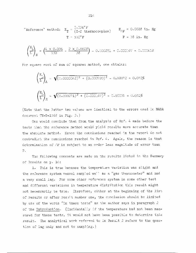
214
'Reference" method: Em =?;°^6^ , n EAp = 0.0028 in. HgT (I-C thermocouples) AP
T = 530°F P = 38 in. Hg
4 x 0.036 2 x 0.0028
530 + 38 )" 0.000271 + 0.000147 = 0.000418
For square root of sum of squares method, one obtains:
f=) = V(0.0000042)2 + (0.000720)2 = 0.00072 = 0.072$A
(yi) =V(0.000271)2+(0.000147 )2 = 0.00031 = 0.031$
(Note that the latter two values are identical to the errors used in NASA
document TN-D-1588 in Fig. 3.)
One would conclude then from the analysis of Ref. 4 made before the
tests that the reference method would yield results more accurate than
the absolute method. Hence the conclusions reached in the report do not
contradict the conclusions reached in Ref. 4. Again, the reason is that
determination of AP is subject to an order less magnitude of error than
P.
The following comments are made on the results listed in the Summary
of Results on p. 16:
1. This is true because the temperature variation was slight and
the reference system vessel sampled well as a "gas thermometer" and had
a very small lag. For some other reference system in some other test
and different variations in temperature distribution this result might
not necessarily be true. Therefore, either at the beginning of the list
of results or after result number one, the conclusion should be limited
by use of the words "in these tests" as the author says in paragraph 2
of the Introduction- (incidentally if the temperature had not been mea
sured for these tests, it would not have been possible to determine this
result. The analytical work referred to in Result 2 refers to the ques
tion of lag only and not to sampling.)

215
2. The comparison is of limited value because comparable precision
was not used in measuring pressure and pressure differences. Thus, the
experimental substantiation is questionable.
3. The reference system error analysis has a term for error due to
determining pressure difference while the absolute system error analyses
has a term for error due to determining absolute pressure of the contain
ment instead. If the latter had the same precision as the former, in
stead of an order of magnitude less, the contributions to the total error
would be the same. The difference in the error analysis is that if one
assumes no lag and no sampling error, the temperature error terms in the
reference system analysis cancel each other out and an error due to de
termining temperature appears only in the absolute system analysis. The
analysis of the lag problem found in NASA document TN-D-1731 indicates
a possible error of 0.02°F due to lag in the 2-in. system. If neglected,
this gives an error term about as large as the one in the absolute sys
tem analysis for thermocouples, but larger than the one in the absolute
system analysis using the nickel wire. The statement should have the
qualifying words "in these particular tests" added. All the error analy
sis really does is show that the poorer precision in determining absolute
pressure makes the reference method more accurate in these tests.
4. Again, the smaller scatter is due to the order of magnitude
higher precision in measuring pressure difference than in measuring total
pressure.
5 and 6. Not enough emphasis is placed on the feasibility and accu
racy of the nickel wire resistance thermometer. A detailed analysis of
sampling error will show that the sampling error using this instrument
is essentially zero and at least smaller than the instrument precision.
In a cylindrical building, a wire stretched from top to bottom on the
axis has zero error for extreme changes in shape of the axial tempera
ture distribution. The results obtained with this instrument serve again
to show that scatter is a result of lack of precision in determining the
pressure and not the temperature.
In conclusion, the summary of results shown on p. 18 of NASA docu
ment TN-D-1731, prepared by the same author, along with results 5, 6,
and 7 of NASA document TN-D-1588, (pp. 16-17), plus a statement to the

216
effect that "had the precision of determining containment pressure been
the same as the precision of measuring the pressure difference, the scat
ter of results would have been the same in both methods" would make an
agreeable, true, and unambiguous set of conclusions which others could
use in selecting their test procedures.
217
Appendix F
COMPARISON OF METHODS OF DETERMINING CONTAINMENT LEAKAGE
RATES AND MAXIMUM POSSIBLE ERROR ANALYSES
R. 0. Brittan*
Introduction
For nearly ten years a heated dispute has been under way in which
proponents of the so-called "reference" method of determining containment
leakage rates contend that the method is superior to the so-called "abso
lute" method. As a matter of fact, both are closely related methods of
observing pressure decay. The reference method is considerably more com
plex in preparation and execution. The same measurements must be made in
both methods, plus additional measurements on the reference system itself
to assure adequate temperature compensation or allow correction for thermal
lag, to assure leaktightness or correct for leakage, and to assure proper
hygrometry or correct for condensation. In addition, the reference system
must be constructed, installed, and tested.
Historically, the reference method was conceived to eliminate the
necessity of making temperature corrections by virtue of assuming equal
temperatures in the leaking containment and in the nonleaking reference
volume, which are coupled by a manometer. If temperatures and hygrometry
(i.e., temperatures above the dewpoint and no liquid water present in
itially) are identical, the leakage rate of the containment is just the
difference in the pressure difference between the two systems at two points
in time divided by the containment test pressure. This first reference
method was attempted in VBWR, which had an allowable leakage rate of the
order of Vf0/2k-hr day. In practice, it was found that a considerable lag
existed between the temperature of the air in the reference volume and the
temperature of the air in the surrounding containment volume, which was
varying diurnally.
Since then, considerable effort has been concentrated on attempting
to reduce this lag to zero and have the reference volume distributed in a
*Argonne National Laboratory.

218
more representative way throughout the containment volume. At the same
time, the reference method (both methods, in fact) has been employed in
testing containment systems for which the leaktightness requirements have
become more and more stringent, approaching allowable leakage rates of a
few hundredths of a percent. For the accuracy employed in practice in
reading temperatures, manometer legs, and barometers, the possible error
(and even the probable error) in determining leakage rates is often much
greater than the leakage rate itself. The error entailed in assuming tem
perature compensation alone is greater than the leakage rate. For very
low leakage rates, the true rate cannot usually be proved by either method,
and any small advantage which one method has over the other is lost. For
either method, where leakage rates are less than 0.001/2U hr, the leak
testing must become a sophisticated experiment to be adequate.
To allow an unbiased comparison of the two methods, it seems important
to set on record the "exact" expressions for leakage rate which are obtained
without assumptions regarding behavior of the state variables or the systems
and then the expressions for the errors in leakage-rate determination which
may accrue.
There are two types of error analysis available to those conducting
leakage-rate tests. One deals with possible error, the other with probable
error. The former is required in planning the tests and as a proof of mini
mum detectable leakage rate. The latter is used in assessing the credence
of the test after it is performed.
The possible error analysis sets the limitation on leakage-rate deter
mination imposed by possible errors in reading instruments or by limits of
accuracy of the instrumentation. It is assumed in this analysis that every
reading error or lack of builtin accuracy is in such a direction (+ or -)
that the total possible error is maximum (+ or -). Comparison of this
maximum with the expected or required magnitude of the quantity to be de
termined (leakage rate) allows determination of the precision of instru
mentation needed to make the possible error a desired fraction of the leak
age rate (e.g., l/3 or l/2).
It may be shown after a test that probability laws yield much lower
errors with high confidence (e.g., 3% or 3%) under favorable conditions.
This analysis may also take into account increased accuracy available

219
through multiple observations of a single variable. Thus, the probable
leakage rate calculated may be proclaimed (with low error) with high con
fidence. It does not absolutely preclude the possibility of the particu
lar test having the maximum possible error.
Herein only the possible error analysis is considered. The expres
sions required for determining the leakage rates and errors are developed
from the basic equations governing gases for the two pressure decay meth
ods (absolute and reference) of leakage-rate determination during pneu
matic tests. Possible errors are compared for the two methods. An assess
ment of importance of changes in volume and in weight of water vapor, and
errors in determining them, is made.
Initially only tests on containment structures under gage test pres
sures of the order of 1 atm or higher are considered. In tests where
the gage test pressures are of the order of 1 lb/in.2, different pres
sure measurements are usually taken (specifically, atmospheric pressure,
difference between containment pressure and atmospheric, and difference
between reference vessel pressure and containment pressure). Such tests
are examined later, although results are found to be the same as for
the reference method.
Possible Error Analysis for Absolute Method
On considering all gases present as perfect gases it is assumed that
the constituents of the air, including water vapor, each and as a mixture,
obey the equation of state:
PV = NmRT . (l)
For purposes of this examination,
P = absolute pressure, psf,
V = container volume, ft ,
T = absolute temperature, °R,
m - molecular weight of gas,
N = number of molecular weights,
R = constant for the particular gas, ft/°R.

220
The product mR is assumed to be the same for all gases, and Nm = w is the
total weight of gas, vapor, or mixture in the container. Deviations from
these assumptions require correction of the measured values only if tem
perature conditions initially and finally vary markedly (e.g., the ratio
of the weights of air and water vapor remains constant above the dew-point
temperature but increases below that temperature, if no water is present.)
In general form, the equations relating the variables for air and
water vapor in the containment vessel are
p V = w R T , (la)^a a a
p V = w R T . (lb)v v v
(Note that partial pressures and weights are given in lower case letters,
and that the subscripts used herein signify the following:
a = air,
v = water vapor,
1 = initial point of measurement,
2 = final point of measurement).
Since p is not measured but P is, and since P = p + p , while w = w + w ,
the equation relating the variables measured is
P-^ = wR +wR =(w-w)R +wR =wR +wh-^--lRo, (lc)T aa vv v v a vv a v\R / a '
but R /R = m /m , and hencev' a a' v
so that
PV /m \= w + w — - 1 (id)
RaT V \mv /
PV /m
w = a-l w . (le)R T \ m / va \ v
Hence at two points in time, t and tg, separated by t — t± = At,

and
P1V!
a i
__L_±
Ra^
221
m1 w
1 w
Then the change in weight of material in the containment vessel is
Aw = w2 - Wl =I— - —-I - (w - w )(--!]\ a 2 ai/ s i \ v /
(If)
(Ig)
(2)
If now P = R + AP, V = V + AV, T0 = Tn + AT, and w = w + Aw [in21 '21 '21 ' v V V
2 1
general X + AX = x(l + Ax/x)] are substituted in (2), and it is noted that
T^ (l + AT/LL^ ) is approximately equal to 11/(1 - AT/LT^ ), since AT/lT^ « 1,it is found that
AwP1V! /o-(1 +p. a i \
However,
1 +
APN
AP
AVN AT>
rvK1-^
AV
V
AT
P!V1R Tna i
(m >
— - 1
/
AP AV _ ATP V Tl l l
(2£
if products of fractional changes (such as AP AV/'P1 V ) are neglected. With
this modification, Eq. (2a) becomes
PV/R\ /AP AV AT\ /m \(2b)
But R/R = m /m and tn = m p + m p /(p + p ), where p = density, and' a a' a a v v' v a Kv' ' r '
p /p = s = specific humidity, so
R
R
1 + s
m
1 +^ sma

222
Also w = P V /R^ . With these substitutions it is found that Eq. (2b)
can be written
(2C;
The fraction of material leaking out in the time interval At (in hr) can
be obtained by subtracting the fraction of water vapor which condenses (in
the containment) from both sides. Furthermore, by multiplying both sides
by 2U/At, this leakage rate can be extrapolated to that for 2k hr. If
these operations are performed, it is found that the 2^-hr leakage rate for
the absolute method is
2k Aw — At*
LA~AT wn
2k
At
1 + s /AP AV AT
mv \ Pn V % /1 + — si i !
ma
Aw / m \-^L _±_ i
w \ m /l v v
Aw,
o:
If the temperature stays above the dewpoint throughout the test,
Awy = 0 and Awy ~ Aw[s/(s + l)], and the 24-hr leakage rate becomes
2k
A At
(1 + s):
]_ +
/AP AV AT'
V 1
(3«
Note that the bracketed term in Eq. (3a) is always in the range 0.99
< [ ] < 1.00 and hence can be taken as approximately 1 with less than
1% error in L'. Thus
2k /AP AV _ ATA ^ AT Il\ V1 \ (3b;
It will be shown that AV/v is less than 0.0001, generally, and usually
may be deleted in determining the leakage rate.

223
To determine the effects of errors in reading instruments or of lack
of instrument precision it may be assumed that each measurement has an
error E of either sign associated with it. Thus the true values are:
T = T + E1 xi - V E
P'w = w ± E , etc,v v w '
If these expressions for the measured variables are substituted in Eq.
(3) for the differences AP, AT, etc.,
lLAjE~ At
1 + s /P2±Ep-Pi±Ep V2±Ev-Vi±Ev T2±ET-Ti±ETNm
1 +^sm
a
Pi Vi Ti
w±E-w±Ew±E— w±E/ \ v w v w
v w y w / m \ c v c v2 v i v [_§__-,] ^ c i c
wx \ v / w(3c)
or
(L ) ~2U^VE ~ At
1 + s /AP + 2E AV + 2E AT ± 2ErE + I _ ->-•
V \ P-,1 + S \ 1
ma
V
Aw ± 2E /v w / m
v | a
w.m
- 1 -
T,
Aw ± 2E
• (3d)
Then the maximum possible error in L is (L.) —L , with all errors addi-A ALA
tive:
\ ™(LA}E LA~ At/2E 2Em 2KA 2E' p T V \ w_
_ + +
P T Vill
2E'w
(0.6) (M
(Note that (m^nL, - l) = 0.608 and (l + s)/[l + (mv/ma)s] ~ 1.)It will be shown that fractional errors in determining hygrometry and
volume changes are small compared with fractional errors in determining
pressures and temperatures and may be ignored for values of LA > 0.0001.
Hence the significant error fraction can be written

224
2U /2E~ 2En
V^bf+T>- <*•>
Possible Error Analysis for Reference Method
In the reference method the same measurements should be taken as in the
absolute method, plus measurements of
6P = pressure difference between reference system and containmentvessel = P — P,
R
T_ = temperature of contents of reference system,R
P = pressure in reference system,R
T = wet bulb temperature of reference system, or
r = relative humidity of reference system.R
(From the T„ and T^ or T and r , w can be computed.)R \ R R v
The governing equations for the containment and reference systems are
1. containment
p V = w R Ta a a
p V = w R T (1)V V V
PV = wRT
2. reference
% VR = WR RaTRa a
% VR = \ RvTR (5)V V
PRVR = WRRTR
The fractional weight change in the containment is still as given by
Eq. (2c). It is only necessary to replace AP with a term containing the
measured values. This is done by noting that
P = P^ - 6P
so that

and
Then
AP
225
Pi =\ ~ 6Pi
P„ = P„ - 6P .2 R2 2
=P2-P1=(PR -PR)-(6P2-6PJ ' (6)'2 1
If P is replaced by w T R/VD and P-d by WD Tr, r/vd as given in•R R^, Rg Rg R1 RL Rx Rx
2
Eq. (5), and if
wR = w (1 + AwR/wR ) ,
\ cV1 +ATr/\and
\ =\ (1 +AVvRi )« v /(i - avr/Vri ) ,
then
W / Awr\ / atr\/ avr\ wr\r
\ RTR /AWR ATR AVR1 ' +,— -,—I. (7)V \ w T V
neglecting products of fractional changes. If this is substituted into
Eq. (6) and then divided by P ,
AP \ /A-R ATR AVR\ (6Fa - 6P, )^'~{\ \'\) ^ ' ^
Noting that
\ /Px +6P^ ^ 6P1 +
pi V pi / V Pi

226
and again neglecting products of fractional changes, Eq. (8) becomes
A5p - 6PAP
P
'AW_R+ATR AVRw TR R1 l
V
\,
If Eq. (8) is substituted into Eq. (3), the leakage rate per 2k hr is ob
tained directly for the reference method:
T _2k\h. ~ At
1 + s
\ in
< m
AT„ AT\ /AV0 AV)K 1 / i\
\ Tl \ Vl
6P2 ~ 5P1 +^RPl +\
Aw / mv / a
- 1w, \ m
1 \ v
Aw
(9)
Again, if both T and T^ stay above the dewpoint and the reference system
does not leak (AwR = 0, Awy = 0), and since Awv = Aw [s/(s + l)],
4* - At(1 + sfm \ / m
ma A \ --.
AT„ AT\ /AV„ AV^R \ I K
\ Ti \ \'6P2 -8P,,
Then, since 0.99 < [f(s)l < 1.00 for the bracketed term in s,
// _ 2kLR - At
fAT_ AT)K
T T\ 1
AV0 AV> '6P2 " 6P!v.. V
(9b)
The following comments are now pertinent:
1. Only now can the effect of the assumption that TRl = Tx and
TR = T2 be assessed. If this were true, AT /^ would cancel ATi/Tx andthe apparent leakage would not include either term. However, TR must bemeasured to prove this, and hence an error can be introduced. In general,
such an assumption is not true because of a real thermal lag between refer
ence and containment system.
2. If the temperatures of the reference and containment systems
always stay above the dewpoint, Awp = Awv = 0, and the last two frac-vc c
tional change terms drop out.

227
3. The above points serve to show where other possible error analy
ses may go wrong.
To determine the maximum possible error in ]A due to reading errors
and lack of instrument precision, the same procedure is adopted as used
to obtain the error in L . Expressions like T ± E are substituted in£\ J. -L
Eq. (9) to yield (ivJ-p- Then ET is obtained by subtracting L_ from
(Ve " LR " At1 + s
1 + — sm
a
2E 2E E +E 2E
TR L P bP_J± + + — + —m \ T T P V_
v \ R 1 1 R
X2E.
V
1
2ETT \ 2E /mM , Wv 8
w^ / w \ mR / 1 \ v
V
2ET
(10)
Again, letting (l + s)/[l + (m /m )s] - 1 and m /m -1=0,v a a v
that usually E = E„
R
, and noting
2k
\ (LR}E \ "At
UET 2E 2E 2Ey 2E+ + fl + +
_ T VR
V w.R
2E 3ET,
(0.6) +
"1 -1
(10a)
Since errors in determining AV, AVR, wR, Awv, and AwVc will be shown to be
small compared with errors in determining AT and 5P, and since a double
error (2Ey) is made in reading manometer leg heights to obtain &P, so that
Eg = 2(uE^), where u converts heights to units of P,
2k Mr . Uet'LR At y p
(10b)
(Note, in previous analyses it was not recognized that in determining
6P a double error can be made because each leg of the manometer must be
read. If another single-reading type of pressure differential measuring
device is used, the coefficient of the first error component can be re
duced from k to 2.)

228
Possible Error Analysis for Low-Pressure Reference Method
If low test overpressures are employed (of the order of 1 psi) a dif
ferent set of measurements is sometimes taken. For pressure, the measure
ments are
1. outside atmospheric pressure,
2. pressure difference between containment and outside,
3. pressure difference between reference system and containment.
Measurements 2 and 3 are usually made with two-legged manometers (two read
ings each per measurement), and 1 is made with a mercury barometer. For
temperature, the measurements are
1. outside temperature,
containment temperature,
reference system temperature,
wet-bulb temperature in containment, or relative humidity,
wet-bulb temperature in reference system, or relative humidity.
Measurement 5 should be taken but sometimes is not. It is necessary to take
measurements k and 5 either to show that the temperature is above the dew-
point or to determine the required correction for change in weight of water
vapor. Measurement 1 must be taken at least to correct the barometer read
ing.
If P-g = outside air barometer reading, H„ and HT are the high and low
manometer leg heights, respectively, and u. converts manometer heights to
pressure in same units as P, using the perfect gas law assumptions, the
equations for this system become
wRTP =PB + li(HH-HL) =V
WRRTR
ML MLR
(11)
The expression for the fractional weight loss in the containment ves
sel is the same as for the other reference method, with
V (Hp - H* ) • (12)\-\

229
The quantity P does not enter into the determination of changes in pres
sure, and hence measurements required for P do not introduce errors in
L_. The leakage rate per 2k hr for this low-pressure reference method can
therefore be written by substituting Eqs. (ll) and (12) in Eq. (9):
AT) 'AV, AV'
V~
V \ \2 2 1
\ +»(\~\)Awr
X
V
Aw /mv / a
m- 1
Aw
(13)
If both T and T stay above the dewpoint and the reference system does notR
leak (Aw = 0, Aw = 0), Eq. (l3) can be reduced to an expression analogousK V
to Eq. (9b): °
T" - 2l+LRT -At
J_J
fAT.R
AV)
v~
P- (?\ ' ^J(13a)
uAH.1 —1
The possible error analysis can be made analogous to the reference method
error analysis if errors in determining volume change and water vapor
change are neglected:
if
2E„ Ve.
T Pr, + pAH1 B '^ 1
E.
«RP-n + uAH
BL
= E,n
(1U)

230
The complete error fraction, if condensation occurs, can be written
,,/% Veh eav eavr Eawr EAwE' =^t[ + + + -+ -+ -1 • (lUa)At \ T P V V„ w„ w ' K J
then
\ At\Tl ^ V! VR \.1 J J- •*-L
Hygrometry Corrections
In order to examine the importance of errors in hygrometry, it is
necessary to get an estimate of the quantities E. /w„ and EA /w inJ to AwR ' R Aw ' l
Kv vterms of errors in reading the wet and dry bulb temperatures. To do this,
it is first noted that a relation between P and T, exists in the normalv d
temperature range which is (noting that this is only for the case of satu
rated or subcooled conditions; i.e., below the dewpoint temperature)
log Py =a + b(Td - i+59-69) •
If Td is in °R and lies in the range 500°R < T < 540°R, and if P is ininches of mercury, a = 0.345, b = 0.0347, and
dP,0.0347 dT,
P dv
5
p =p +Ap = p (l+Ap/p ) = p (l+ 0.0347 AT.*V V V V v V' V V c
2 1 1 11
Since, in general,w R T,v v d
P„ =v V
it follows that
from which
w R T, w R I,v v d v v d
2 2 1 l (1 + 0.0347 ATJ ,V V d'
w — w Aw T V0v v v d 2
-V^- = w- = tTT" (1 + °-03U7 AV - 1Vl Vl d2 X
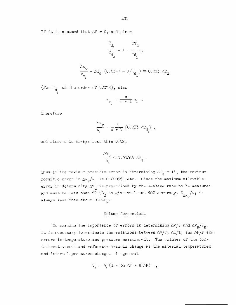
231
If it is assumed that AV = 0, and since
1U AT,&L d
t7~ =1~ t7~
Awvw -ATd (0.0347 - 1/Td )^0.033 ATd
vi
(for Tn of the order of 500°R), alsod1
sw = ——t- wnV s + 1 1
Therefore
Aw
— =~T (°-°53 AT, ) ,w s + 1 d '1 1
and since s is always less than 0.02,
Aw
—- < 0.00066 AT., .w d1
Thus if the maximum possible error in determining AT = 1°, the maximum
possible error in Aw /w is 0.00066, etc. Since the maximum allowable
error in determining AT, is prescribed by the leakage rate to be measured
and must be less than 62. 5L„ to give a,t least 50$ accuracy, E /wi isK AW
always less than about 0.04l_.
Volume Corrections
To examine the importance of errors in determining AV/V and AV /V ,
it is necessary to estimate the relations between AV/V, AT/T, and AP/P and
errors in temperature and pressure measurement. The volumes of the con
tainment vessel and reference vessels change as the material temperatures
and internal pressures change. In general
V = V (l + 3a AT + p AP) ,21

232
where a is the linear temperature coefficient of expansion of the vessel
material and B is the pressure coefficient of expansion. For spherical
vessels,3r
2e hs
where
r = sphere radius,— s
h = wall thickness,
e = elastic modulus of sphere material,s
For tubes or cylinders
5r^
where
c2e h
c
r = cylinder or tube radius,
e - elastic modulus of tube or cylinder material.
Since
and
^ =3a AT +3APl
I—J =3a(AT +2ET) +P(AP +2EAp) ,
EAV /AV\ /AVV^ =6QET +2PEAP =(-) "VV"i \i/E i
where E = error. For steel, a ~ 10~5/CF and e ~ 3 X 10⁷ psi; for copper,
a ~ 10"5/°F and e ~ 1.6 X 10⁷ psi.
If, typically, rs/h ~ 1000 and £c/h ~ 25, and the containment is of
steel and the reference system is of copper,
E<-6 X 10"5 E + 10 X 10 5 E
V T P

233
and
EAv—— = 6 X 10"5 Em + 0.8 X 10 5 EVR TR PR
E is constrained to be less than approximately 60L and E is less
than UaL to insure that ET is less than L/2. Hence E.,,/V will alwaysLR AV i
be less than 0.004L for 1 atm overpressure (a = 2). Similarly ET mustR
always be less than 30L and E less than 2a,L. Hence EAV/V1 will alwaysbe less than 0.002L for 1 atm overpressure (a = 2).
The magnitude of AV/V itself is small. It can be seen that for this
example
— = 6 X 10~5 AT + 10 X 10"5 AP .
Hence AV/V will always be less than L/2 if AT < U000L (°R) and AP < 2500L
(in. Hg). Hence for L = 0.001, if AT < k°R and AP < 2.5 in. Hg, AV/V will
be less than 0.0005. Thus an error in determining AV/V is certainly
negligible.
Required Precision
It was noted earlier that the magnitudes of possible errors can be
used to determine the precision required in measuring the temperature and
pressure before the test. This information can then be used to select
adequate instrumentation for the test. Equations (Ua) and (lOb) for the
possible errors can be utilized to obtain the maximum sizes of errors in
measurement which can be tolerated without having the error in leakage-
rate determination be greater than a desired fraction of the expected
leakage rate itself.
Let
, _ Fractional error in leakage rate due to pressure errors / v^ ~ Maximum allowable fractional leakage rate
or, fromEqs. (ka) and (10b),
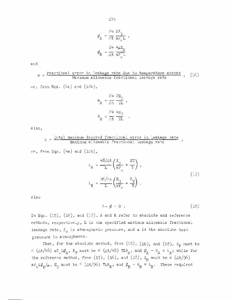
and
234
2k 2EP
A At aPQL '
2k VEHR " At aP L
o
Fractional error in leakage rate due to temperature errors /-.,-<Maximum allowable fractional leakage rate '
or, from Eqs. (ka) and (10b),
2k 2E„
6A =
Also,
At
T
TL
2k UetAt TL
Total maximum desired fractional error in leakage rate
Maximum allowable fractional leakage rate
or, from Eqs. (ka) and (10b),
XA48/At /E ET
-£- + —vaP Tx 0
h96/At /EH ET
\aF" +T,
(17)
Also
x= 0 + e . (18)
In Eqs. (15), (l6), and (17), A and R refer to absolute and reference
methods, respectively, L is the specified maximum allowable fractional
leakage rate, PQ is atmospheric pressure, and a is the absolute test
pressure in atmospheres.
Then, for the absolute method, from (15), (16), and (18), Ep must be< (At/U8) aP L0 , E must be ^ (At/U8) TL9 , and 0 + 9 < X ; while for
the reference method, from (15), (l6), and (l8), E„ must be £ (At/96)
aP L0 /p., E must be ^ (At/96) TL6 , and 0 + 9 ^ X . These required

235
precisions can be evaluated for a = 2, P0 =30 in. Hg, T = 530°R, p = l/l3-6.
0=9= 0.25, X = 0.50, and At = 2k hr, for various values of L. The re
sulting minimum precisions required in reading pressure and temperature
measuring devices are listed in Table F.l.
Table F.l. Minimum Precision Required in Leakage-Rate Tests
L, Maximum AllowableFractional Leakage
Rate in 2k hr
E, Minimum Precision Required
Absolute Method Reference Method
(in. Hg) (°R) (in. H20) :°r;
0.05 0.38 3.3 2.6 1.7
0.01 0.075 0.67 0.51 0.33
0.005 0.038 0.33 0.26 0.17
0.001 0.0075 0.067 0.051 0.033
0.0005 0.0038 0.033 0.026 0.017
0.0001 0.00075 0.0067 0.005 0.0033
These precisions would insure that the possible error in determining
leakage rate is less than 50$. For other values of a, T, p, 0, 9, or At,
the values In the table above must be multiplied by a/2, T/530, l/l3-6p,
U0, kQ, or At/2U, respectively. If these minimum precisions are realized,
errors due to determining the change in weight of water vapor and the
change in volume may always be neglected. Error due to the former is al
ways less than O.O^L and to the latter always less than 0.01L.
Summary
The leakage rates have been determined in terms of the measured
variables for the cases of I, absolute method; II, reference method; and
III, low overpressure reference method. All of these methods are based
on pressure decay and determine the fractional loss of weight of the air
and water vapor mixtures by leakage from the system. The differences lie
in the methods of measuring the equation-of-state variables (pressure,
temperature, and volume) for assumed application of the perfect gas laws.

236
The exact expressions for these 2U-hr leakage rates are (with products of
fractional changes neglected)
Aw
I.
II.
III
L -^LA " At
\2k
At
1
1 +
+ s /AP AV AT\ Awv /n"m" I P"~ +V~ _ T~/ _ w V
V X 1 ! 1 ' 1X
1+s
1 -
AwT
1 + X
2kAt
1 +m
Aw,.
X
Aw m
mv
Aw
p(AH-R2
ahRi
pA^
i \ AwAw /m \ v_Z -^-1 c-w \ m / w
l v v ' i
V
(3)
(9)
(13)
It has been shown that errors in determining Aw and AV are negligible,
as is AV/V itself, in determining the leakage for fractional leakages
greater than 0.0001. It is noted that the expressions for L^ and LR areLi
identical, since
and
JP -6P1 = ptAhL^ -AFL )^
PB +p(AHi)l
In fact, the pressure measurements are the same for 6P and AIL, although
an additional set of measurements is required to obtain P in III.
It is noted that the temperature terms in II and III cancel only if
the reference system and containment system temperatures are exactly equal.
This is not true in general because of thermal lag. Hence it is necessary
to measure reference vessel air temperatures. This is usually not done
and the temperature terms are dropped. If AT /T is different from AT/TX

237
by At/2^L, a 100$ error is introduced immediately by assuming equal tem
peratures. If the readings are taken 2^4 hr apart and the leakage fraction
is 0.001, the temperature differences must agree to within approximately
0.5°F to keep the error below 100$.
If the low-density liquid manometers can be read to the same linear pre
cision as the mercury barometer, the accuracy in pressure difference measure
ment in the reference method is l/2 p„/p times greater than in the absolute' B' m
method (pR is density of barometer fluid and p is density of manometer
fluid). For a mercury barometer and a water manometer this factor would
be approximately 6.8.
For all methods, if the temperatures are kept above the dewpoint, no
correction is necessary for hygrometry in the three methods, since no con
densation occurs and the values of s = p /p is a constant throughout thev a
test if additional water is not available for evaporation. If the tempera
tures fall below the dewpoint, the quantity of water vapor leaking out
with air or condensing must be accounted for continuously throughout the
test, since s is not constant. The same is true if liquid water is present
and available for evaporation.
With these expressions for leakage rate it is shown that the maximum
possible fractional errors, ET, in determining these leakage rates, due tob
reading errors or lack of instrument precision, are given by the following:
II,
III
E -§it/2E
\ p
2Il +2Il)T V '
2E 2E,
(0.6)+-w _
2e nw
v
e -Si-VEr, ^Eq
H2E-'Vr 2E.
V2EwR 2E,
(0.6) +V.
RT V
Only the first two error terms are important in I, II, or III. By introduc
ing a = P /Pg = pressure in container in atmospheres and assuming T = 520°?.,
these two expressions can be rewritten and the maximum possible percent
error in the 2U-hr fractional leakage rate (assuming At = 2k hr) can be
displayed graphically. Here it will be assumed that pE = (l/l3-6) E
(i.e., the same precision in linear measurement). ThusP

238
and
where
«< I00 T,% error in L. - —.— ETA LA LA
0.39 + 6.7
Of • T 100 T? I,7. , |Ed \ |ETl1°erroT inLR "%= \c-7' F3*)^ '
ETT = inches of water error for each leg of manometer,n
E = inches of mercury error,p
ET = degrees Rankine error,
L = fractional leakage rate.
The percent errors in L for At = 2k hr and E /L = 1 for both the
methods are displayed in Fig. 1.* To obtain percent error for other values
of At and E /L, values from the curve must be multiplied by 2k/At and E /L.
It can be noted that for the same precision of linear measurements, the
reference method gives smaller percent error in L for values of E /aE >ir 1
0.067 and larger percent error for values of E /aE < 0.067-
As an example, suppose that the leakage rate is 0.001 for 2k hr, and-
that At is 12 hr. Then If E and EP
E = 0.1°R, and a = 2,
E.H
aE,,
and
H
E
_^aET
0.1 in. of Hg and H 0, respectively,
0.5
100
Then the absolute method yields 3-71+ X 100 X 2 = 7^8$ error in L and the
reference method yields 1.27 X 100 X 2 = 25^$ error in L.
If the precision of measuring Ex and E were increased to 0.01 In.6p P
ETT/aEm = E /aE„ = 0.05. For this case, the absolute method yieldsn' 1 pi
0.73 X 100 X 2 = 1^5$ error, whereas the reference method yields 0.82 X
100 X 2 - l6kj0 error.
*See Fig. 3-3, in Chapter 3

239
Appendix G
CVTR IN-PLANT TEST PROGRAM
An in-plant testing program to be conducted on the Carolinas-Virginia
Tube Reactor (CVTR) was proposed to the AEC and initiated by Phillips
Petroleum Company (Plant Applications and Engineering Tests Branch),
with participation by Carolinas-Virginia Nuclear Power Associates, Inc.,
the operators of the reactor. The program, almost all of which is perti
nent to containment systems testing, is divided into two phases. The
first phase was conducted as part of CVTR's power demonstration program
during the course of normal reactor operation. The second phase, involv
ing special high-risk tests, will be carried out after final shutdown of
the reactor.
1. Phase I — Preliminary Testing Program
Two of the three tasks under phase I are pertinent to containment
systems testing: (l) evaluation of existing operating data and (2) pre
liminary continuous leakage-rate tests.88* Both tasks have now been com
pleted by CVTR, and the data compilations and test results are being
evaluated. These tasks are described below.
1.1 Evaluation of Existing Operating Data
1.1.1 Purpose
The purpose of this task was to determine the usefulness of CVTR's
standard operating information in evaluating the performance and reli
ability of engineered safety systems. Considerable test, inspection, and
operating history data were taken primarily to assure operability of the
various systems and components and to provide reference for their proper
maintenance. These data are considered to be reasonably typical of the
type of information normally recorded by power reactor operators. The
information obtained from review and evaluation of these data will be
related to the Reliability Monitoring Program Study being conducted by
*See Reference Section at end of text.

240
Holmes & Narver, Inc., -under subcontract to Phillips, and will aid in
the development of this program. The data review will also be useful in
determining what other information should be routinely recorded by power
reactor operators in support of safety evaluations and whether differences
exist between the designed and actual operation of engineered safety fea
tures.
1.1.2 Procedure
A review was made of existing data on engineered safety systems and
components, including those related to the containment system, such as
the vapor container, ventilation system, isolation valves, etc. These
data are available in the form of operating and maintenance log books,
work orders, daily records of instrument-electrical activities, equipment
card files, check sheets from scheduled tests, and unusual incident re
ports. This information will be examined for data concerning the frequency
and type of component and system failures and their causes and effects;
the number of times a safety system has been tested or required to operate,
why it operated, and the results; any difference between the design per
formance and the actual operation of an engineered safety system; and the
causes and effects of any unusual incidents and/or emergency situations.
In addition, any information on these incidents will be examined for per
tinence in evaluating engineered safety systems.
The data review was initiated in May 1967. Holmes &. Narver, Inc.,
is under subcontract to Phillips for this task and for relating the data
to the Reliability Monitoring Program Study. The review will cover the
entire CVTR operating history from prestartup checks to final shutdown.
1.2 Preliminary Continuous Leakage-Rate Tests
Due to an unscheduled power shutdown of the CVTR because of fuel
failure, only limited continuous leakage-rate testing was performed. The
additional pressure and humidity instrumentation originally planned for
use in phase I (mentioned below) will not be installed until equipment
is readied for the phase II integrated leakage-rate tests.
1.2.1 Purpose
The purpose of this task is to obtain data to help determine the
accuracy and sensitivity of the continuous leakage-rate measurement

241
system employed at CVTR. The effects of environmental conditions on the
leakage-rate measurement system were also Investigated, as well as the
system s response to a known leakage rate.
1.2.2 Procedure
Performance of the preliminary continuous leakage-rate evaluation
program was an extension of the present leakage-rate tests with additional
and more accurate instrumentation and detectors.
Continuous leakage-rate tests are conducted at the CVTR during reac
tor operation. The leakage rate is measured by the reference-vessel
method at a vapor container overpressure of approximately 2 psig. Mea
sured quantities of makeup air maintain the 2-psig overpressure and pro
vide an additional check on the leakage rate. The relative sensitivity
of the continuous leakage-rate measurement system was determined by using
an adjustable known-leakage-rate device installed in a suitable contain
ment penetration line to superimpose a known leakage rate for a given
period of time.
1.3 Additional Instrumentation
A brief description is given below of the additional instrumentation
and experimental apparatus installed or to be installed in CVTR for this
task and/or tasks in phase II.
1.3.1 Air Temperature Measurements
Calibrated thermocouples were Installed in the vapor container, with
the number of thermocouples in a given horizontal segment proportional to
the relative free air volume in that part of the container. Approximately
2500 ft of bare nickel wire was similarly distributed for use as resistance
thermometers. Also, a few highly accurate (0.02°F) temperature-measuring
devices were installed.
1.3.2 Humidity Measurements
An additional humidity-measuring system will be installed in the va
por container to more accurately determine changes In moisture content of
the containment air. It will have five different sampling locations so
that a representative sample of the containment atmosphere will be ob
tained.

242
1.3.3 Pressure Measurement
Instrumentation will be installed to measure reference-vessel pres
sure, barometric pressure, containment-vessel pressure, and the differ
ential pressure that develops between the containment vessel and the ref
erence vessel.
1.3.4 Reference-Vessel System
The existing reference-vessel systems are used, but double valving
was installed in the containment reference system isolation line to help
prevent leakage from the reference system during the test period.
1.3.5 Superimposed Leakage Rate
The known-leakage-rate apparatus will consist of a tap from the va
por container, a pressure regulator, a calibrated gas meter, and a tap to
the stack.
The limited phase I tests were performed, with the reactor shutdown,
beginning March 11, 1967 and ending on April 2, 1967.
2. Phase II
Phase II will begin about two months after final CVTR reactor shut
down and continue for at least six months. Programmatic changes in phase
II tasks resulted in the elimination of plans for further continuous leak
age-rate testing at the CVTR.
2.1 Objectives
A leakage-rate testing program has been carried out at CVTR in com
pliance with the technical specifications.39>40>89 The second phase of
the in-plant test program will (l) determine the sensitivity and adequacy
of present leakage-rate measurement techniques; (2) obtain experimental
information on the containment vessel and penetration assemblies that can
be used to extrapolate leakage-rate test data from ambient temperature to
design-basis-accident (DBA) conditions; and (3) perform containment sys
tem tests under simulated DBA conditions, first with hot air and then
with steam, to determine the effect of these conditions on the leakage
rate, penetrations, vessel strain, equipment, and safety system operation.

243
2.2 Plans
2.2.1 Integrated Leakage-Rate Tests
Integrated leakage-rate tests similar to those conducted to assure
compliance with the technical specifications will be performed by pres
surizing the vapor container and allowing the pressure to decay over a
period of time. The leakage rate will be determined both by the refer
ence-chamber method and by the absolute-pressure measurement method. At
the end of the decay time, the vapor container pressure will be returned
to its original value and the amount of makeup air will be measured to
provide a third independent check on the total leakage.
Tests will be run at 6, 13, and 21 psig in ascending and descending
order to evaluate the relationship between the leakage rate at low and
high test pressures. At 13 psig, two additional tests will be run, one
with containment air at normal atmospheric humidity (~50$) and one with
containment air at a very low humidity (<5%). These tests will be made
to investigate the effect of containment atmosphere humidity on the leak
age rate and leakage-rate measurements. The existing equipment used for
the integrated leakage-rate tests required by the CVTR technical specifi
cations will be utilized for these parametric studies, along with addi
tional instrumentation, including humidity-indicating equipment and tem
perature-measuring devices.
2.2.2 Penetration Leakage-Rate Tests
Leakage-rate testing of representative penetration assemblies in the
vapor container will be conducted under various environmental conditions.
These test conditions will be accomplished by enclosing individual pene
tration assemblies within a special apparatus supplied with steam. Par
ticular attention will be given to tests on electrical penetration assem
blies because of their susceptibility to aging and deterioration. Experi
mental data for the extrapolation of ambient-temperature leakage-rate data
to determine the leakage rate expected at DBA conditions will be obtained.
Potential methods for carrying out integrated leakage-rate tests at DBA
conditions will also be evaluated on a small scale by using the special
apparatus for an environmental test chamber.

244
2.2.3 Containment DBA Tests
An extensive series of simulated tests under design-basis-accident
conditions is proposed to determine the effects of DBA conditions on a
typical containment system. The following four DBA-type tests are pro
posed.90^!
2.2.3.1 Hot Air Test. To evaluate the effect of temperature, the
initial DBA-type test will be conducted with hot air. The containment
vessel will be pressurized to 21 psig, and high-capacity heaters will be
used to raise the atmosphere at constant pressure (21 psig) to approxi
mately 215°F. The heaters will then be programmed so that the heat input
balances the heat loss and steady-state conditions are established. The
following measurements will be made during this test.
Containment vessel leakage rate. Integrated leakage-rate measure
ments similar to those made at ambient temperature will be made at 21
psig and 215°F. The leakage rate at these conditions will be compared
with the previous ambient temperature leakage rate so that the added
effect of temperature can be determined.
Containment vessel strain. Prior to starting the high-temperature
integrated leakage-rate testing, the containment vessel steel liner will
be instrumented with strain gages. Base-point strain measurements will
be made at ambient temperature and various pressures up to and including
21 psig during the initial pressurization in preparation for the high-
temperature leakage-rate testing. Additionally, strain measurements will
be obtained at several intermediate temperatures during heating and at
the maximum temperature during the hot-air leakage-rate testing. By tak
ing strain measurements at several conditions, a good basis for compari
son will be established.
The CVTR strain measurements will provide valuable data that will be
directly applicable to current and planned power reactor systems. The
CVTR containment vessel (steel-lined concrete) is typical of several cur
rent power reactor containment vessels, particularly those for Palisades,
Turkey Point, H. B. Robinson, and Connecticut Yankee reactors.
Equipment effects and safety system operation demonstration tests.
The ability of safety systems and key safety equipment components, such
as valves, switches, pumps, instrument sensors and readout, etc., to

245
function properly during a design-basis accident and/or in a DBA environ
ment is essential to the safety of a power reactor. In particular, fol
lowing an accident an accurate knowledge of the reactor condition is re
quired before proper action can be taken. Therefore, this portion of the
proposed program will be directed toward quickly checking the operational
status of safety systems and key safety equipment under DBA conditions to
determine whether they work properly and give a correct indication of the
existing reactor and plant conditions. The equipment items to be checked
will include control-rod drives and associated instrumentation; nuclear
instrumentation channels; and primary coolant flow-, temperature-, and
pressure-indicating instrumentation. Since much of this equipment was
originally designed to operate under DBA conditions, this test will also
be a proof test of the equipment design.
Three safety systems will be placed in operation — the emergency in
jection system, the emergency cooling system, and the air-recirculation
system. Each system will be operated long enough to insure that the indi
vidual components (pumps, motors, valves) are functioning properly and
that the system as a whole is operating correctly. The safety systems
operational tests are not intended to obtain reliability information, but
to answer one question — will a safety system installed to limit an acci
dent operate in an accident environment? In developing detailed test
plans for these tests, the CVTR emergency procedures will be reviewed
and used as guidelines in the selection of the specific Instrumentation,
controls, and safety systems to be tested.
Additional information. During the hot-air leakage-rate tests, in
formation will be obtained on the thermal properties of the CVTR contain
ment system, and the heat capacity and steady-state heat transfer data,
such as heat losses, temperature profiles, etc., will be determined.
This information will be useful for comparison with calculated values
and can be used as input to containment-response computer codes.
2.2.3.2 Steam Test — Natural Decay. The initial, simulated DBA
steam test will be performed by rapidly bringing the containment atmo
sphere to DBA pressure conditions (21 psig) with steam, shutting off the
steam flow, and allowing the containment atmosphere to return to ambient
conditions by natural decay. Steam for this test can be supplied from

246
South Carolina Electric & Gas Company's Parr Steam Plant. CVNPA presently
supplies steam produced at CVTR to the 400-psi 725°F header at the Parr
Steam Plant through a 10-in. steam line. With suitable minor modifica
tions, steam can be supplied in a reverse direction through this line from
the Parr plant header to the CVTR containment system. The boiler capacity
at the Parr plant for this header is 400,000 lb/hr (~1. 5 X 10⁵ Btu/sec),which, if supplied to the CVTR containment vessel, can produce simulated
DBA conditions in approximately 100 sec. A 100-sec rise time to contain
ment DBA conditions is representative of a severe loss-of-coolant acci
dent. Additionally, if the steam flow is allowed to proceed for 175 sec,
the energy added to the CVTR containment system will be approximately
equivalent (based on Btu per cubic foot of containment volume) to theDBA energies postulated for release into the Connecticut Yankee and
H. B. Robinson PWR containment vessels. Performance of this latter
175-sec test would be contingent on the ability of CVTR's containment
structure to withstand the resultant pressure and temperature buildup
associated with the additional energy input.
A primary objective of this test is the accurate measurement of the
pressure-temperature-time history of the containment atmosphere. The
data will be compared with predictions calculated by the CONTEMPT code92and other such computer codes, if available. An evaluation will then be
made of the ability of the computer code(s) to predict the containment
atmosphere response to the simulated DBA. In addition, while the system
conditions are decaying to ambient conditions, the tests that were per
formed during the hot-air test (discussed in a previous section) will be
repeated, including leakage-rate, vessel strain, equipment effects and
safety system operation, and thermodynamic measurements, so that the
added effects of a steam atmosphere can be determined.
2.2.3.3 Steam Test - Containment Spray. A second simulated DBA
steam test will be performed to determine the containment response to,
and the effectiveness of, a typical containment-pressure-reduction spray
system. This test will be performed by using steam to bring the contain
ment atmosphere to DBA conditions. The spray system will be actuated in
Lhe normal manner and measurements made of the pressure-temperature-time

247
history of the containment atmosphere. Containment-vessel strain measure
ments will also be made, provided the strain gages remain intact after
the initial steam test. The experimental pressure-temperature-time data
will be used to compare with and evaluate the calculated containment re
sponse from computer codes.
An additional and important objective of the spray system test will
be to demonstrate the effectiveness of such a system and thereby estab
lish a design basis for this engineered safety system. Examinations of
safety analysis reports indicate that containment spray systems being
installed in current PVR and BWR plants vary considerably in design and
purpose. For example, of four systems examined, flow rates varied from
500 to 4000 gpm. Generally, the basic purpose of the spray system is
pressure reduction; however, an additional function for some systems is
cleanup of fission products in the containment atmosphere following the
DBA. Consideration will be given to the use of additives, such as basic
acid and sodium thiosulphate, to evaluate system corrosion and possible
nozzle-clogging effects.
Because of the similarity between the CVTR containment structure
and that of the Connecticut Yankee reactor, the spray system to be in
stalled in CVTR will be patterned after the Connecticut Yankee system.
The Connecticut Yankee spray system is designed with a relatively high
flow rate-to-contalnment volume (up to ~1.6 X 10"3 gpm/ft3); therefore
additional testing with the CVTR system could be performed to simulate
pressure-suppression spray systems with lower flow rate-to-containment
volume ratios, such as that of the H. B. Robinson power reactor system
(~4X 10~4 gpm/ft3). Based on the Connecticut Yankee system and scaled
on a flow rate-to-containment volume ratio, the CVTR pressure-suppression
spray would require a flow of about 400 gpm.
To thoroughly check out the CONTEMPT code, it may be necessary to
perform spray tests at two different flow rates and vary the nozzles to
produce at least two different ranges of droplet size.
2.2.3.4 Steam Test - Core Decay Heat. The final, simulated DBA
test will be a steam test similar to the previous two tests with the addi
tion of a heat source to simulate the fission-product decay heat of a

248
power reactor core. For this test, the containment system will be rap
idly brought to DBA conditions with steam and immediately subjected to
a programmed heat source produced by continuing the steam flow at an ever-
decreasing predetermined rate and/or by using electrical heat.
Preliminary analysis shows that such a test can be performed with
steam, since the steam supply is more than adequate to simulate large
power reactor core-decay heating scaled to CVTR's containment vessel on
the basis of Btu's per cubic foot of containment volume. The sequence
of this test will require further analysis to determine (l) the size of
the simulated heat source and at what point it should be removed and
(2) when the pressure-suppression spray should be activated. During
this test, as in previous tests, the pressure-temperature-time history
of the containment system will be measured, and the data will be used to
evaluate analytical predictions of the containment response.
Consideration will be given to measuring the steam condensation
rates on the inner surface of the containment vessel wall and on a num
ber of representative surfaces of the major heat sinks in the contain
ment system. Also, the feasibility of performing steam-distribution,
quality, and convection-velocity measurements during and subsequent to
the initial steam injection will be investigated.

249
Appendix H
CONTAINMENT SYSTEMS EXPERIMENT
The Containment Systems Experiment (CSE) will be used to examine the
course of a range of simulated loss-of-coolant accidents in water-cooled
reactor containment systems. In the experiments, tests will be made of
the transport behavior of fission products in a containment system, the
rate of loss of coolant from the primary system, the consequent mechani
cal loadings produced on various reactor and containment system compo
nents, the efficiency of engineered safety features (such as recircula
tion filters, sprays, and pool suppression) in reducing containment sys
tem pressure and fission-product mobility, and leakage characteristics
of typical containment structures. As may be seen, the CSE program em
phasizes areas other than developing methods of testing containment sys
tems.
The basic objective of the leakage-rate tests planned for the CSE is
to relate the leakage of fission-product activity from a containment sys
tem to the leakage rate measured with air by the customary techniques. The
leakage-rate tests will begin with room-temperature air-leakage tests at
several pressures and levels of leakage rate, and the sensitivity and mag
nitude of errors involved in such tests as usually performed will be in
vestigated. Following the tests with ambient air, experiments will be run
at elevated temperatures. These hot-air tests will be performed at several
pressures representative of steam-air mixtures at the same pressures.
Steam-air tests will follow to explore the effect of representative acci
dent temperatures, pressures, and atmospheres on leakage rates. Finally,
the leakage of fission-product aerosols at representative containment ves
sel leak points will be measured during the fission-product transport tests.
Equipment for the CSE consists essentially of a large containment
vessel and a model reactor vessel. The model (reactor primary) vessel
is 42 in. ID, 17 ft high, has a volume of 150 ft3, and is designed for a
maximum pressure of 2500 psig at 600°F. Dummy cores and other internals
can be installed in the model vessel. The containment shell is 25 ft ID,
66 ft high, has a volume of 30,000 ft3, and is designed for an internal

250
pressure of 75 psig. Provisions can be made for using fission products
and simulants for testing engineered safety features. The construction
of the CSE facility is essentially complete. Preliminary leak tests were
concluded, and detailed studies of leakage began in December 1966. Initial
aerosol transport and blowdown tests began in the spring of 1967.
The completed and planned leakage-rate tests consist of the follow
ing tests designated series L-l through L-6.
Series L-l. The tests in series L-l consisted of the initial shake
down leakage-rate tests of the containment vessel as a whole, including
the dry well and the wet wells. The tests supported the specific objec
tives listed under items 1 and 2 in Section 4.1 and were performed with
the vessel in the "as-is" condition; that is, without extensive leak lo
cation and repair efforts. However, major leaks were repaired, and the
resulting leakage rate was between 1 and 10$ of contained weight per day
at 70 psig. These tests were carried out with incomplete penetrations;
that is, not all containment valves had been installed and the final elec
trical and instrument wiring penetrations had not been completed.
Series L-l involved tests at six pressures between 5 and 70 psig
with ambient-temperature air. The measurements made and the data taken
were basically pressure, temperature, humidity, and flow rate as required
for integrated leakage-rate measurements by the absolute and reference-
vessel techniques and for leakage-rate measurements for individual leak
points. These measurements are common to series L-l, L-2, and L-3.
Shakedown tests with normal air continued intermittently until late
April 1966. During this period, installation of heating devices, aerosol-
sampling devices, typical penetrations, etc., was completed in preparation
for subseqiient test series. Leakage tests were interspersed with the con
struction activities to develop experience in operational techniques.
This series was completed.
Series L-2. Series L-2 tests were similar to those of series L-l in
objectives, test conditions, and measurements, but all penetrations had
been installed. The objective was to determine ability to make meaningful
and accurate leakage-rate measurements as a function of pressure and the
level of leakage rate. Tests were performed at a minimum of three pres
sure levels and at three levels of leakage at each pressure. Pressures

251
were 10, 30, and 60 psig and nominal leakage rates were 0.1, 0.5, and 1.0%.
Increases in scatter of data at lower leakage rates will be examined fur
ther as indications of the feasibility of measuring and verifying very low
leakage rates. The leakage rates were varied by varying the degree of
tightness in the various penetrations. Normal air was used, and leakage
was measured at individual penetrations for comparison with data from
later steam-air tests. This series of tests was completed, and data
analysis is in progress.
Series L-3. The tests of series L-3 were an extension of series L-2
tests with operational penetrations complete. In these tests the trend of
air leakage as a function of pressure was examined further. At a level
of leakage determined from the preceding series (0.1$/day at 60 psig),
several new pressure levels were tested to examine extrapolation from
low-pressure tests, presence of critical flow phenomena affecting ex
trapolation, and comparison of individual leakage at typical penetra
tions with total leakage. The tests were run with normal air and traces
of xenon to form as large a body of statistical data as possible (in
conjunction with preceding series) on the leakage rates of penetrations
and the basis for comparison with later tests with steam-air mixtures
and fission-product aerosols. Tests were performed at pressures of 60,
45, 30, 15, 10, 5, and 1 psig. The tests of this series were completed,
and data analysis is in progress.
Series L-4. The series L-4 tests have the objective of investi
gating extrapolation of leakage-rate data from tests with low-tempera
ture air to postaccident (loss-of-coolant) conditions of steam plus air.
The planned test pressures will cover three values for which air-leakage
rate data will be taken for the individual penetrations just prior to
the start of series L-4; tentatively, the pressures will be about 10,
20, and 30 psig.
These tests will involve only direct collection and measurement of
leakage at individual leaks. Integrated leakage-rate measurements based
on the perfect gas law are not feasible, so the total leakage rate must
be taken as the sum of the individual leaks.

252
Series L-5. Series L-5 is included with the objective of determining
the effect of air temperature alone on leakage rate. The tests will cover
three combinations of pressure and temperature of an air atmosphere to
correspond to the pressure and temperature levels of series L-4 with a
steam-air atmosphere. Direct measurement of leakage rates at the indi
vidual penetrations will be made. Integrated leakage-rate measurements
with the gas-law methods will be attempted, but because of the large tem
perature gradients and temperature changes expected with time, the re
sults may be subject to large uncertainty. The containment air will be
heated with steam space heaters located in the containment vessel and
remotely controlled to provide the required air temperature.
Series L-6. Series L-6 includes tests to investigate the leakage of
fission-product aerosol through representative containment leakage paths.
Experimentally, these tests will be performed during the course of runs
primarily for investigating fission-product aerosol transport. During
these tests, periodic samples of the containment atmosphere will monitor
the aerosol concentration near the entrance to a leak path previously
characterized as to leakage rate as a function of pressure and atmosphere.
Leakage of the steam-air-aerosol mixture will be collected in samplers,
and from these data the decontamination, if any, in the leak path can be
determined.

253
Appendix I
LOSS-OF-FLUID TEST
The LOFT test program, which involves modeling a loss-of-coolant
accident in a 50-Mw(th) nuclear plant, is intended to increase knowledge
of the possible consequences of the accident (see Refs. 84 through 87 at
end of text). The objectives of LOFT are to provide information (l) to
assist in establishing criteria for the design of plant equipment vital
to safety and engineered safety systems, (2) to assist in determining
the relative importance of the phenomena that occur during the accident
sequence, (3) to establish the reliability in extrapolating results from
laboratory and small-scale experiments, and (4) to assess the validity of
analytical models developed to describe all or portions of the accident.
The overall LOFT test program consists of the following five phases:
(l) containment leak tests, (2) blowdown tests, (3) reactor tests and op
eration, (4) loss-of-coolant tests, and (5) postaccident examinations.
In addition to phase 1, some parts of phases 2 and 4 are pertinent to
containment systems testing.
1. Facility Description
The reactor is installed within a dry containment vessel 70 ft in
diameter and 97 ft high, with a volume of 302,000 ft3. After considera
tion of the design-basis accident (DBA) for LOFT, which hypothesizes a
complete blowdown of the primary and secondary systems, plus energy con
tributions from reactor decay heat and from 100% metal-water reaction,
the containment design pressure was established at 40 psig.
To ascertain containment integrity before each test, to establish
leakage rates as a function of pressure and temperature, and to allow
remote decontamination of the containment vessel interior following a
planned fission-product release, several special provisions are to be
incorporated in the LOFT building. Features pertinent to containment
systems testing are an internal concrete missile shield, pressure-reduc
tion sprays, leakage-rate measuring equipment, and monitored penetrations.

254
The facility provides for the removal of the entire reactor system
from the containment vessel through a large door equipped with a pressur
ized double seal. In fact, the general philosophy of design of all access
doors has been to preclude leakage by employing double seals with the
capability of annulus pressurization to twice the containment system de
sign pressure.
All other penetrations have double seals, such as double-potted con
nectors in electrical cable penetrations and double isolation valves in
piping connections. With this arrangement, the fission-product leakage
through each penetration can be collected, the penetrations can be pres
sure and leak tested independently of the containment vessel, and the
gross leakage through penetrations can be measured when the containment
vessel is pressurized with either dry air or a steam-air mixture.
The capacity of the original containment spray system was increased
substantially at the suggestion of ACRS to provide for more rapid pres
sure reduction in the containment system. As a result, a conservative
analysis indicates that the containment pressure can be reduced from the
accident peak to 2 psig within 1 hr and to 1 psig in 1.3 hr. Spray de
livery rate and secondary coolant flow rate are both set at 1000 gpm.
2. Phase 1 — Containment Vessel Pressure and Leak Tests
Phase 1 of the experimental program is designed for investigating
the containment pressure and leak characteristics. A series of tests
will be performed to insure that the air leakage rate from the contain
ment vessel meets the design specifications and to determine the leakage
rate as a function of pressure. These tests are expected to provide a
high degree of assurance that the containment vessel will withstand the
pressure associated with primary coolant blowdown, as well as information
on the leakage rate as a function of pressure. This information is needed
for a correlation of the data on air leakage rates with the data on leak
age rates of fission products in air-steam atmospheres to be obtained in
phase 2 for a final assessment of the radiological hazard that may pre
vail during the loss-of-coolant tests (pha.se 4) and for interpretation
of the final results of the loss-of-coolant tests (phase 5).

255
The first series of leak tests, which are normally considered as
acceptance tests, will be performed by the construction contractor to in
vestigate the pressure capabilities of the containment vessel and its
leakage rate. The second series of tests will be performed as part of
the experimental program to determine the leakage characteristics of the
containment vessel. These tests will include (l) determining the total
leakage rate from the containment vessel as a function of pressure, (2) de
termining the leakage rate through containment vessel penetrations as a
function of pressure, (3) calibrating and adjusting controlled leaks,
(4) determining the ability of the operational and test instrumentation
to function properly under pressure conditions, and (5) evaluating exist
ing techniques, as well as techniques that may be developed in the future,
for measuring containment leakage.
Consideration is being given to carrying out several of the leak
tests with radioactive tracers to gain early information on fission-prod
uct leakage and the filtration effect of the penetrations. All leak tests
in this series will employ dry air at ambient temperature. Leakage-rate
measurements will be made with both the absolute and the reference-chamber
methods.
2.1 Tests Performed by the Construction Contractor
The containment vessel will be pressure tested to 46 psig (115$ of
design pressure) at the conclusion of vessel erection, with the railroad
door in place and the penetrations capped, but prior to installation of
internal facilities and experimental apparatus. The total leakage is not
to exceed 0.2 wt $ of the vessel free volume in 24 hr at the design pres
sure of 40 psig at this stage of construction. At the conclusion of con
struction, with all piping and electrical penetrations completed, the
vessel will again be pressure tested to 46 psig. (During these pressure
tests, containment vessel strain will also be measured.) Leakage from
the completed containment vessel is not to exceed 0.2 wt $ of the build
ing free volume in 24 hr at an internal pressure of 24 psig.
The 0.2$ leakage criterion is sufficient to preclude excessive doses
at the boundaries of the National Reactor Testing Station. If further
reduction of leakage through the penetrations is desired, the plenum

256
between the double seals of the penetrations can be pressurized to above
the pressure existing in the containment vessel.
2.2 Tests Performed as Part of the Test Program
2.2.1 Leak Tests at Several Pressures. This portion of the phase 1
leak tests consists of determining the total gas leakage from the contain
ment vessel at the pressure expected during the loss-of-coolant test and
at several lesser pressures. This information is needed to predict with
some assurance the fission-product leakage to the surrounding environment
and the subsequent radiological hazards that may prevail during conduct
of phase 4 of the program. It will also provide some information on the
reliability with which the leakage rate at high pressures can be predicted
from measurements made at low pressures.
The containment vessel will also have a controlled leak of known
size located near the coupling sta.tion. The gas leakage rate through
this controlled leak will be determined as a function of pressure. The
fission-product leakage through this controlled leak will be captured by
filters and analyses made to provide information on fission-product leak
age through an orifice of known geometry, size, and air leakage rates.
Since this orifice will offer a minimum of resistance to fission-product
leakage, information can be obtained to estimate the minimum filtration or
fractionation of fission products that can be expected in passing through
a leak path. Other techniques for measuring containment leakage will also
be evaluated.
2.2.2 Pressure and Leak Tests Involving Radioactive Tracers. Trace
quantities of 130i and 85Kr will be released to the containment vessel
during a pressure test in an attempt to determine the filtering effect
of the controlled and monitored leak paths for radioiodine and to deter
mine the general location of uncontrolled leak paths. In addition, these
tests are expected to provide some early data on iodine-retention qualities
of the containment vessel walls and equipment surfaces.
The filtering effects of the leak paths will be determined by mea
suring the radioiodine concentration inside the containment vessel and
in the penetration filters. The internal air will be continuously

257
circulated throughout the test to provide a homogeneous distribution of
the radioactive tracers.
2.2.3 Leak Tests During Other Phases of the Experimental Program.
A leak test at 24 psig will be performed prior to each coolant blowdown
test not involving a release of radioactive materials. Prior to the tests
involving a release of radioactive materials, the controlled leak will be
calibrated and adjusted to give a total leakage rate, through controlled
plus uncontrolled leaks, of 0.2$ of the free volume per day.
3. Phase 2 — Loss of Coolant Test with a Dummy Core
Phase 2 of the experimental program consists of a series of prelimi
nary coolant blowdown tests to (l) investigate the effects of rupture size,
rupture location, coolant temperature, and coolant pressure on the response
of a nuclear plant, (2) determine the effects of rupture size and location
on the transport of fission products to the containment building, and
(3) evaluate the reliability and effectiveness of the containment vessel
to retain fission products and the spray system to reduce the pressure
and, thus, to terminate the fission-product leakage from the containment
vessel.
3.1 Nonradioactive Blowdown Tests
Coolant blowdown through 4-, 10-, and 18-in.-ID openings will be in
vestigated as a function of primary coolant temperature (450 to 600°F)
and pressure (1200 to 2500 psig). Ruptures will be simulated in both
inlet and outlet pipes as near as practical to the reactor vessel.
This phase of the program will be performed on the complete nuclear
system, except for the core. A dummy core will be installed to provide
the same flow restrictions that will prevail during the actual core melt
down test. Data to be obtained during blowdown tests will include
(l) pressure and temperature of the containment environment as a function
of time, (2) strain on the containment vessel and the temperature gradient
through the vessel walls, and (3) containment vessel leakage rate as a
function of time. The leakage-rate information is needed to determine
the rate that can be expected during the phase 4 loss-of-coolant tests.

258
By comparing these data with those obtained during tests with air, the
effects of elevated temperature and an air-steam atmosphere on contain
ment leakage can be established.
Following at least one of the blowdown tests, the containment spray
system will be activated, and the time required to reduce the containment
vessel pressure to atmospheric pressure will be determined. During this
time, flow rate and temperature of the spray water will also be measured.
The purpose of this experiment is to verify that the spray system meets
the design requirements. However, the data obtained will be useful in
evaluating the effectiveness of engineered safety features of this type
for reducing containment pressure.
3.2 Fission-Product Transport Studies
The series of nonnuclear blowdowns will be concluded with tests ac
companied by the release of trace quantities of -L30i and 85Kr.
The purpose of these tests is to (l) determine the rupture location
that provides the maximum transport of fission products into the contain
ment vessel, (2) determine the space-time history for the transport of
iodine and krypton to the containment vessel, and (3) determine the plate-
out behavior of iodine in the reactor vessel, primary coolant system, and
containment vessel.
In addition to pertinent measurements previously mentioned, the io
dine plate out on the containment vessel walls, the iodine and krypton
concentrations in the containment atmosphere and outside the containment
vessel, and the iodine concentration in the water collection sump will be
determined as a function of time. At least one test of this series will
again involve operation of the containment spray system.
4. Phase 4 — Loss-of-Coolant Tests with Radioactive Core
Phase 4 of the program is undergoing extensive review at this time.
From the standpoint of containment systems testing, it is to be expected
that the scope of the tests, measurements, and techniques will parallel
quite closely the fission-product transport studies to be made in phase 2.