building esearc note - krc.cbri.res.in:8080
TRANSCRIPT

CENTRAL BUILDING RESEARCH INSTITUTE ROORKEE-247667 (INDIA)
BUILDING ESEARC NOTE
BRN33
NOISE AND ITS CONTROL
Introduction
The notab le growtl1 in engineering scie nces the development of new sources of power tile uses of mechan ica l equipmen ts and the increasing degree of automation and mechanism have increased the noise problems in ve ry sphere of li fe Noise is a by-product of Civilization Industrial progress has brought in its wake Jl oiser macll ines and economy in bu ildings construct ion has given ri se to ligl l te r walls and part itions Wit ll conseq uent loss in insu lation aga inst no ise Noise is produced in almost all rnectlanical and industri al operat ions A part of tile mect1a llical energy app lied in these operations is consumed as Ileat and a small port ion is radiated as noise Tile transmiss ion of sOllnd from its sOLl rce to the recepient may take place in a Il umber a ways depend ing upon wh ether it is air borne In the former it is tra nsmitted fro m one pa rt of the building to the another by direct air path eg through windows and doors etc in the latte r it is transmitted by means of energy carried by th e structu res eg impact no ise thro ugh floors etc in Fig 1
Fig 1 Air-borne and structure-borne noise transmiss ion tilroug ll a pan ition
This Research Note deals basically with household noise traffi c noise and industrial noise
Properties of Noise
Noise may be broadly as unwanted sound It may be intelligible or un- intell igible depending upon wh ether it is described as speech or sound of a maclline The annoyance caused by noise is purely a subjective ptlenomenon Sometimes even a low noise is a matter of great conce rn because the overall sound press ure levels do not give a true indicat ion of the annoyance and hence one must determine the frequency composit ion of the no ise No ise composed of low frequency so unds may be as annoying as the wlline due to tl ig h freq uen cy sounds Narrow band no ise is more disturbing th an broadband noise of equal loudness as for instance the so und of an automobile horn in the midst of con tinuous broadband traffic noise on the ro ad Most of the noise produc d in industrial operations is ull-inte lligible but becau e of its large sound pressure levels and complex frequ ency content it becomes a cause of much annoya nce and fat igue On the other land inte ll igible sounds cause interference in conversat ion and 1he speaker Ilas to 1alk in a ra ised or loud vo ice
Measureme nt of noise
Noise is usually measu ed and expressed in terms of sound pressure level (SPL) If P is the pressure of the ound wave its SPL is expressed In decibels as
SPL= 20 log 10 ppr dB
Where pr ( 2 x 10middot~ Pascal) is the reference pressure and also lowest sound pressure that an average human ear call perct ive DeciiJe l is a convenient un it for e~pressing the SPL and the noise reduction achieved by sound
absorbing materials at various frequencies may be represented in Ihe form of a graph between SPL and freque ncy Th is is called spectrog ram gives the distribution of so un d ene rgy among the va riolls frequen cies compris ing noise Noise can also be analysed in half or third octave bands in order 10 obta in greater deta ils of energy distribution A sound leve l meter is used to measure overall sound pressure leve ls It is used in environments where noise is steady or where Ihe fluctuat ions in leve ls are not very large Altern atively noise can be recorded on magnet ic
tape for subsequent analysis in tile laboratory
Origin and Types of Noise
Most of the no ise produced in urba n residential areas in is ai rborn e such as rad io T V schools rail and aircraft no ise etc Th is noise interacts with the performance of human beings and causes discom fo rt and distractio n Wh ere the noise is intelligible and in terferes with co nversat ion speech interference levels become important paramete rs to be seen Wideband noise in the frequency ra nge
TA BLE
Speech in te rfere nce levels (i n dB) wh ich bare ly permit re li able conversatio n at th e distance and voice leve ls indicated
Distance between ta lker and listener (meter)
0 1 5
030
060
090
12
15
1 8
36
Voice level (decibels above 00002 micro-bar)
Normal Raised Very Loud Shouting
71 77 83 89
65 71 77 83 59 65 71 77
55 61 67 73
53 59 65 71
51 57 63 69
49 55 61 67
43 49 55 61
600-4800Hz mas s speech freque ncies and thus reduces speecll intelligibi lity Table I shows speecll interference levels wh ich bare ly pe rmit re liable conversalion at the distances and vo ice leve ls indicated
Depending upon the type of activity maximum permissib le background no ise leve ls are recommended as no ise criteria loads Table II slwws NC levels for varioLi s act ivit ies Table III shows maximum permissible octave band leve ls for backgro und no ise for differe nt activities given in Table II It becomes necessa ry therefore 10 measure the overall noise leve ls existing in a place and then compare it with the appropriate NC curve to know the
amount of acoustica l insulat ion needed fo r a part icular act ivi ty Typical pa rtit ions and their insu lation va lues are given in Appendices A amp B
One of the most common problems in build ings is the impact noise It is caused by an object stri king or slid ing on a wall or fl oor tructllre such as fo otsteps dropped toys or cooki ng pans moving furniture door siammmg etc In all the se cases th e fl oor is set into vibra tio n by direct impact or by mechanica l co ntact and sound is radiated from both the sides of floor
The tech nique of constra ined layer damping is generally applied for isolat ion of impact noises
TABLE II
Types of acti vities and U)e criteria for backgro und Noise (NC)
NC 20-30 Broadcast studios large conference rooms hospitals libraries houses (sleeping areas)
apartments and hote l rooms
NC 30-40 School rooms music rooms assembly tl a lls qu iet office small conference rooms
NC 40-50 Large engineering and drafting rooms rest aurants NC 50-60 Bus in ess Machine rooms
TABLE III Maximum permissible octave band leve ls of backg round noise for different activit ies
shown in Table II
Sound pressure level in decibels re 00002 micro-bar
Frequency Band It)
It)
0 It)
0 0 M
6
0 0 ltD 6
0 0 N ~ 0
0 0 v N 6 0
0 0 co v 6 0
0 0 ltD m 6 0
M l)
l) 0
M 0 ltD
N v N
co v
NC-25 57 49 39 32 28 25 22 21
NC-35 63 55 47 41 37 35 33 32
NC-45 69 62 56 50 47 45 43 42
NC-55 76 69 64 59 57 55 53 52
tal
ClJ04IH ________ eONCII(fE
6em T~IC
WIIU MUH
Fig 2 VISCOELASTIC OR SANDWICHED CONSTRUCTION BETVVEEN THE VIBRATING STRUCTURE amp LOWER STRUCTURAL SLAB
Basica lly this technique provides for dissipation mechanical energy in the form of Ileat generated by physica l distort ion of a layer of viscoe lastic material sandwicll ed between the vibrating structure and the lower structura l slab as shown in fig 2 Various res il ient materials such as Bartex Kurlon Fiberg lass etc have been tested and the ir re lative performance is given in Table - IV An Impact Noise Rating of zero means sat isfactory
performan ce of a res ilient floor A rating of plus or minus sig n indicates better or worse perfo rmance of a floor respect ively Quite different class of noise is produced by machines and processes associated with the production and handling of goods in industries In case whe re the process itself is quiet noise from common equipmellts sLlch as fans blowers furnaces etc may be ~ u ite high When
Table IV Impact Noise rat ing of sandwiched res ilient materials
Mate rial Thickness cm
Impact Noise Rati ng (I NR) According to Indian Standard
Laboratory Field
Bare Concrete Bartex Kurlon Fibreglass Fibreglass Spintex Therrnocole Linoleu m Hollow-pan un its Asbestos Mineral woo l
200 400 127 5 00 250 2 50 042 600 127 2 50
- 16 - 1 +12 +5 +1 1 +7 - 5 - 7
+510+15 +10
- 13 +3
- 8
Thickness of fibreg lass in the field test was 40 em (un loaded) The variation in rating of asbestos is due to the different quali ties tested
115
110
105
100
90
85
JU NCTION OF THE TWO SHADED AREAS IND ICATE S MEAN LEVEL amp THE FI GUR ES IN THE BRACKETS GIVE THE LOUDN ESS OF THE NOISE
I ~ ~ ~ ] ~
~ ~ u e ~ U ~ l F Ci5 l ~ shy~ ~ a~ cmiddot Q t
~ e E
1 bull Fig 3 RANGE OF NOISE LEVELS OF WORK AREAS OF SOME INDUSTRIES
I RANGE OF PEAK LEVELS OF IMPAC T NOISES WITH THEIR DECAY CONS TAIfT~
NOI SE LEVELS AS INDI CATE D BY A SOUND LEV EL METER~
150 teshy
~
I ~
~ 140 middotr ~
euro middotr ~
I I
~ ~ J
c~
130
co middotr2 ~ g
~ II
IJ 120l ~
~ I ~
~ ~ I
~ amp u
-J 110E ~ ~C l ~ ~ ~
100 ~ ~ ~ 90
~ II II
i ~LtJ f l il a i J 11 Ji
Ii tI
0
ai ~ e d III s i
~j t Q l a ~- a J ~ ~ u t -t ~
Fig 4 NOISE LEVELS IN EXCESSIVELY NOISY INDUSTRIAL PROCESSES
Located close to a residential area noise due to processes like riveting and forging or from a service equipments like compressor and exhaust fans can be a major source of nu isance to residents Noise levels in production areas of some major industries are shown in Fig 3
Fig 4 depicts noise levels measured workers ear during various operations
Factory noises are either continuous transient Cont inuous noises may again be steady or fluctuating A transient noises may consist of a sharp burst of sound quickly dying off or a number impulsive sounds repeCitedat short intervals of time
Continuous and steady noise in factories are genera lly produced by (i) machines rotating at constant speeds like motors compressors etc (ii) reciprocating and vibrating machines like shake out and found ries and sieves in coke batching
and (i ii) escaping gases like exhaust from pneumatic tools or hissing noise from spray guns fans etc Machines usually produce low and middle frequency noises corresponding to the ir rp m and harmonics whereas exhaust gases give rise to high freq uency noise with both level and freque ncy increasing rapid ly with escape velocity
Continuous but fluctuating noise is commonly found in machine shops and metal fabrication and material handling areas In such areas miscellaneous noise due to cutting hammering or metal parts hitting against one another are heard above the steady back gro und noise produced by motors fumace etc Steady noise in these areas generally consist of low frequency sounds while the superimposed noise often contains middle and high frequ encies
Secondal) effect of such noise are also seen Jhen the impact of noise is transmitted without much attenuation
along the factory floor to distant parts of the building or shock absorbing devices like steel springs or other throwing windows and loose ly fitted tin roofs into vibration proprietary mou nt ings
Methods of Noise Control
Noise sho uld be taken as an importan t consideration at every stage of a building design While planning noise control measures in advance enta ils only small increase in construction cost correct ive measures are often very expensive Foll9wing measures sliould be taken
a) Careful locat ion ofthe site b) Choosing appropriate insulation c) Reducing the noise at source d) En closing the source of noise e) Use ofsoLJnd absorbing materia l
Location of bui lding should be chosen very judicioLlSly with reference to the su rrounding environment fo r example an auditorium close to a noisy th oroughfare or a rotary press above or close to the editorial room should be avo ided Similarly an industrial set LIp should not be planned in a residential co lony Within the building itself placement of noisy and quiet areas must be done with great care and wherever possible the type of act ivity ant iCipated in a part icular area must be clearly laid down in the beg inn ing itse If
Once ant iCipated Of measured ambient noise levels are known in an area adequate exercise must be done to ach ieve re commended acoust ica l cond itions with in the space by properly choosing sound insulati ng partition or wall Cho ice of a sou nd insulating partit ion should be made from a knowledge of the characteristics of the prevai ling no ise and th e desired degree of quietness on the other side of the partition Criteria for quietness fo r different activities are given in Table amp II I
Reducing noise at or near the source is obviollsly the most effective and eCo nomica l method of noise contro l Since tile level of noise produced by a source is directly proportional 10 its amplitude of vibration si zeable reduct ion in noise can be effected by using the minimum power necessary to drive the source It shoLlld be seen that th e maintenance of machinery is regularly done at appropriate interval of time Reduction of structure borne noise and vibration can be achieved by interrupting th e rigid path between the source and the other parts of the middot structure by resi lient materia Is like felt glass wool or rubber
Low frequency noise and its transmission to other areas in multistoryed factories can be reduced by ant i vibration devices The machine may also be mounted on a heavy concrete base fl oating on resili ent mounts and iso lated from the rest of til e floor by a cork or loose sand fill ed gap around th e perimeter It is important that the resilient material used is not loaded beyond its elastic limit
Most common way of con tro lling the noise is to completely enclose the source by a hig hly insulating structure Dimensions of the enclosure depend on the size of the source work progress invo lved and materia l handling req uirements etc In choosing a partit ion for an enclosure its average so und transmission loss which is the average insu lation in the frequency range 125-4000 Hz s tlOuld be taken as gu ide (see Append ic s A amp B) Acoustica l absorbe rs are poor sound insulators and hence should be used only for lining the inside of enclosure to increase its efficiency All joints shou ld be carefully sea led to avoid direct air leakage path In some cases instead of enclosing the whole mach ine only covering its noisy part has been found to be sufficient Where it is not possible to cover a mach ine part ial enclosures and non-porous barriers lin ed with sound Insulating material on the noisy side can be used Noise in higilly reverberant areas (such as large halls etc) can be contro lled by the use of sound absorbing mat ria ls appli ed on walls ce iling of the building or by employing functiona l sound absorbers Fun cti ona l abso rbers are most effective in shops where machines are closely spaced Appendix C gives a few sO Li nd absorbing materia ls w ith the ir sO Li nd absorption coefficlen ts
Prolonged exposure to very high noise levels may result in permanent and incurab le hearing loss and lead to what is known as industria I dea fness Even brief exposure to noise levels of 90 to 95 dB is known to cause temporary loss of hearing It is genera lly agreed to that where an individual is exposed to cont inuous no ise of 90 dB for 8 hours the risk of damage to hearing exists For eve ry 5 dB increase in the level the exposure time shou ld be halved to avoid hearing loss In case of very high noise levels lise of ea r plugs or the other protective measures must be made Exposure to sounds of 135 dB and above even fo r a few seconds has bee n known to cause instantan eous ru pture ofill e eardrum
APPEND IX A
Specificat ion for Wa lls
SOUND TRANSMISSION LOSS VALUES IN dB
Sr No
Name of the Material will1 designed Specification
Total thickness
(cm)
Mass dens ity Kg m~
STL in DB
1 Sing le leaf wa lls or partitions we igh ing more than 390 kgm Bri ck wall With modular bricks -- 00-shyDense concrete -shy 00-shy
228 3048
35 254 38
488 590 707 634 927
50 53 53 52 55
2 Cavity wall each leaf we igh ing approx 95 kg m Two 11 4 em brick leaves wit) Scm Cavity ( wire ties) Double 10 cm clinker block with Scm cavity th in wire ties 1 25em plaster on both sides
278
27 5
488
312
SO-53
50
3 Single leaf masonry wa ll we ighting more than 176 kgm 11 4 cm bri ck wa ll with 125 cm plaster on both sides
139 2684 45
4 Cavity walls eactl leaf we ighing approx 75 kgm or more a) Dou ble 5crn clinker block with 5 crn cavity
tll in wire ties 125cm plaster on bottl sides 175 185 47
b) Double 7 6 crn clinker block with Scm cavity th in wi re ties 125 cm plaster on both sides
227 244 49
5 Staggered Stud Walls Gypsum wall board 125 cm on opposite sides of staggered 5 x 10 cm wood studs 406 cm DC Wood fiber blanket 228 cm thick Stapled 10 studs in one set
10 67 45
6 Single leaf masonry of weight at least 11 0 kgm~ a) 7S em clinke r block 125 em with plaster
on both sides 10 120 30-41
b) 10 cm clinker block 125 cm wittl plaste r on both sides
125 165 38-43
c) 20cm hollow clinker block 125 cm with plaster on both sides
225 35-42
7 Cavity wall w ith each leaf weigh ing at least 50 Kgm Double S cm wood wool slab with S cm cavity thin wire ties 125 em plaster on both sides
175 97 6 42
1
8 76 cm Hollow clay block with 125 cm plaster on both sides or 76 em clinker wit111 25 em plaster 75-10 108-122 36-39 on one sIde or 5 cm clinker block with 125 cm plaster on both sides
9 3 mm sing le glass panes 03 8 28
10 Double wall glass pane 3 mm each with 085 16 34 25 cm air gap
11 Coconut Husk slab 25 10 23
12 Plibastos Bu ildings Boards 04 238
13 Wood wool Boards 375 15middot20 20
14 Isobar Glass double layers 31 30-40 35
15 a) Mica based steropole Panel 2 5 cm 3 192 20 thick w ith 3 mm plywood on both sides
b) Mica based steropole Pane l 25 cm thick 27 488 22 with 2 mm alumin ium on both sides
16 Polyurethene foamed pan el 38 15 28
17 a) Bison PanelCemenl Bonded Wood 16 20 38 Part icle Board
b) Bison PanelCement Bonded Wood 12 156 35 Particle Board
18 Expanded Polystyrene Composite Door 25 245 shutter without frame
19 Red mud po lymer Hallow Core Door Pla ne 40 40 33 surface witl10ut frame
20 Top line ceil ing tile 12 84 27
21 a) PVC Integral Sheet 14 23
b) PVC Integral Foam Sheet 19 256
22 AAC Blocks (Aerated Au toclaved Co ncrete) a) Without plaster 10 62 5 38 b) With 15 mm plaster on both sides 13 67 44 c) Without plaster 20 125 42 d) With 15 mm plaster on both sides 23 130 47
23 a) Fibre reinforced plast ic panel 25 32 5 b) Fibre reinforced plastic pane l with lead sheet 25 34 5
on one side and wire mesh on other side ~
24 228 cm C-Brick with 125 cm plaster on both sides 253 470
25 Double I af C-Brick wal l 25 cm air gap 278 52 0
7
26 a) b)
Particle Board Particle Board
12 25
8 4 17
Lr 0 3 1 -
27 a) b)
Gypsum Board Gypsum Board
5 10
45 90
310 350
28 Heavy Wo oden Door (Rubber gasket arou nd sides) 6 62 95
29 Conventional Door 37 40 266
30
31
Double door (10 cm gap)
Poly Carbonate twin wa ll Sheet
17 4
6
80
1 33
3 17
1139
32 Acrylic Sheet 3 318 11 04
33 Po ly Carbonate Transparent Sheet 3 361 1916
34 Coloured Glass Sheet 4 788 25 94
35 Coloured Glass Textured Sheet 3 7 93 27 99
36 Plain Glass wit h Black Film 3 864 28 74
37 Heat Refl ecting Glass Sheet 5 12 56 3207
38 Hea t Refl ecting Glass Sheet 6 1345 32 07
39 Plain Glass Sheet 6 1353 30 62
40 Heat Reflecting Glass Sheet 6 1536 33 73
41 Rein fo rced GI3ss Sheet 6 1606 411
I bull
APPENDIX B
Air borne sound insulation of windows
Situation where used Type of window Transmission
loss
(decibles)
1 Bed ro oms or lecture theatres facing
arte ri al roads major roads Witll heavy
traffiC side roads with in 18 to 45 m of
heavy tra ffic
2 Marg inal for the above situation and
and living rooms class rooms fac ing
thoroughfare
3 Bed rooms class rooms facing resshy
idential roads with local traffic or minor
roads living rooms facing heavy traffic
4 Lecture theatres and bed rooms facing
qu iet areas living rooms facing res ideshy
nt ial road traffic
General offices facing heavy traffic or executive offices faCing minor traffic
o r liVing rooms)
Double window of 730 gm or 900 gm
glass spacing 203 em tightly sealed
with absorbent in reveals (better insshy
ulat ion aga inst low frequency rumble if
125 em plates are used)
Sa me as (I) but spa cing 10 crn
Sing le 05 cm plate glass window all
edges sealed
Single 730 or 900 gm glass window all
edges sealed
Some as (4) in wood or metal framesshy
openable
40
35
3Q
25 shy
20
1
Append ix C Sound Absorbing materials with the ir Noise Reduction Coefficient
Sr No Materials Manufacturers Thickness Density NRC mm Kg mJ Ran2e
1 Twiga Fibreglass Mis UP Twiga Fibreglass 50 32 Ltd Sikandrabad Bulandshahr UP
2 Spintex (Resin Bonded) Mis Punj amp Sons Pvt Ltd 50 65 090 to 098 New Delhi
3 Fibreg lass Crown 200 RB-3 MIs Fibre glass Pilk ington Ltd 50 32 Mumbai
4 Fibrosil MIs Ind ian Rockwool Co Ltd 50 De lhi - 6
5 Twiga Fibreglass as above 50 24 080 to 089 6 Spintex as above 50 65 7 Fibreg lass Crown 150 (RB-2) as above SO 8 Twiga Fibreglass as above SO 24 9 Miheral fibre resin bonded MIs Lloyd Insulation (I) Ltd SO 25
New Delh i 070 to 079 10 Fibrosil as above 25 11 Spintex as above 25 49 12 Fibreg lass Crown 100 (RB) as above 50
13 Fibreg lass Crosn RB-2 amp RB-3 as above 25 24 14 Fibreg lass rigid board as above 25 060 to 069 15 Supercera Ceramic Fibre MIs LLoyd Insulation (I) Ltd 40
New Delh i 16 Minwool Insulation Board 15-9-495 Mahaboobganj 50 120
Hyderabad
17 UniformlyRandomly perforated MIs Gurind Sa les 13 300 Jolly Board 60 Janpath N Delhi
18 Fibreg lass Crown 100 (RB-1) as above 25 16 19 Wood woo l insulation board Fibrecrete Woodwool lnsulation Board 25 350 050 to 059
Pahargan h New Delhi 20 Duratex woodool board MIs BK Industries 25 400
Netaji Subhash Marg New Delh i 21 Cerool blanket MIs Orien t Carwool Ltd 30 128
Nehru Place New Delhi
22 Thermotex MIs Vijay Udyog Industrial Area 25 375 Bulandshahr Road Ghaziabad
23 Armstrong Ceiling Tiles MIs Inarco Ltd 15 250 040 to 049 East Pate l Nagar New Delhi
24 E-glass needle mat MIs Maharaja Exhaust Product Pvt Ltd 15 160 Rani JhansiMarg New Delhi
Prepared by RK Srivastava RL Dhabal Published by Central BUilding Research Institute AnujSalnl Roorkee - 247667
Revised in April 2004 E-mail dlrector3cbrimailcom Website wwwcbrlorg
bull Edited by Dr Atul Kumar Agarwal amp Shrl Dlnesh Scientists Printed at Paramount Offset PrImers 7 Avas Vlkas Roorkee Ph 261l ~8 2641 7
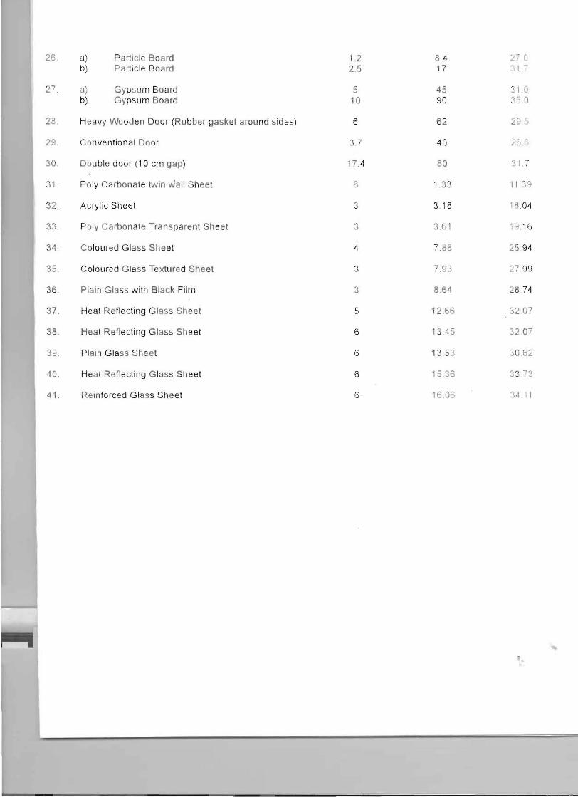