certification of the h-pt. and backset measuring equipment and … · this activity makes for every...
TRANSCRIPT

VDA - Spezifikation November 2009
Empfehlung für eine Vorschrift zur
Standardisierung und Kalibrierung von H-Punkt- und Kopfstützenmessgeräten
VDA xxx
Seite 1 von 15
VERBAND DER AUTOMOBILINDUSTRIE E. V. (VDA) Westendstraße 61 60325 Frankfurt
Certification of the H-Pt. and Backset measuring equipment and its calibration

Seite 2 VDA xxx VDA - Spezifikation November 2009
VERBAND DER AUTOMOBILINDUSTRIE E. V. (VDA) Westendstraße 61 60325 Frankfurt
Contents
1. ..........Introduction .............................................................................................................3 1.1. Background.............................................................................................................3 2. ..........Objective .................................................................................................................4 2.1. Application...............................................................................................................4 3. ..........Standard of measuring Equipment..........................................................................5 3.1. CAD-Data................................................................................................................5 3.2. Dimension Sheet HPM I..........................................................................................5 3.3. Dimension Sheet Structure .....................................................................................8 3.4. Dimension Sheet HRMD .......................................................................................10 4. ..........Calibration.............................................................................................................12 4.1. Description ............................................................................................................12 4.2. Dimension Sheet HPM I........................................................................................12 4.3. Dimension Sheet HRMD .......................................................................................13 5. ..........Perspective ...........................................................................................................13 6. ..........Annex....................................................................................................................14 6.1. Terminology ..........................................................................................................14

Seite 3 VDA xxx VDA - Spezifikation November 2009
VERBAND DER AUTOMOBILINDUSTRIE E. V. (VDA) Westendstraße 61 60325 Frankfurt
1. Introduction
1.1. Background
The Hip point or H-Pt. is an important value for the design of car interior and its seats. In many different specifications, regulations and legislations, eg. FMVSS202a, EuroNCAP, ECE R17, etc. the H-Pt. has to be measured. For this measurement is a so called Hip-Point-Manikin, HPM is necessary. This manikin developed in the 50’s by the US Army was adopted as US SAE standard SAE J826 in November 1962 for H-Pt. measurements. The manikin shells were defined with sec-tional cuts and the structure using a few dimensions and weights incorperating huge toler-ances. Later on came a new development the ASPECT dummy, also called HPM II. Result-ing in defining the old as HPM I. Since its development the the HPM I was copied and manufactured by several companies. The moulds were always handmade according to the Reference templates. The production stopped after 300 HPM’s as there were no more required and the moulds were subse-quently scrapped. A remakes of the HPM’s was simply solved with cast negative forms from the existing shells. Over the years came several revisions of the SAEJ826 including further information about weight, measures and tolerances culminating in the the actual production. At the moment there are most probably 1000 HPM I in use worldwide. However because of the above mentioned production history, they all differ in dimensions, forms and weight. As IIWPG started with the evaluation of headrests regarding whiplash, RONA developed the HRMD as adaption for the HPM during the 90’s. There to with the additional demands of FMVSS202a and EuroNCAP the H-Pt. and Backset gained increasingly more importance. Unfortunately checks using the HRMD’s also showing some very illogical deviations. This being highlighted by measuring comparisons made on the same seats using different HRMD’s which producing very different results, subsequently recognised the big differ-ences in manikins as the cause. Thereapon Thatcham introduced the GLORIA. As GLORIA is only based on the former tolerances and not the contours of the shells, the VDA seat safety committee decided to define exactly the HPM I and HRMD in contours, measure-ments and tolerances based on todays technical standard.

Seite 4 VDA xxx VDA - Spezifikation November 2009
VERBAND DER AUTOMOBILINDUSTRIE E. V. (VDA) Westendstraße 61 60325 Frankfurt
2. Objective
The VDA letter of recommendation XXXX comes in two steps. First step is the precise definition of the HPM I and the HRMD in its dimensions, shape, po-sitioning, weight and tolerances with special onus to the SAEJ826 NOV2008 to reduce the tolerances caused by the equipment to a minimum. HPM I and HRMD have been defined independently to ensure their interchangeability. Second step the calibration is the regular check of the functional dimensions of the equip-ment to keep and abide to the reached standard. The data of shape, position, dimensions, weight and tolerances should be available for every user to give him the possibility to update the measuring device and to keep and abide to the standard. This activity makes for every Manufacturer and Institute precise measuring of H-Pt. and Backset possible without incurring big tolerances. This resulting in large cost reduction, sav-ing extensive series of measurements and comparisons incorperating expensive changes and eliminating retests. For Common practice and patency it would be appreciated if Eu-roNCAP Whiplash protocol, ECE R17 and/or IIWPG protocol would accnowledge and inte-grate the recommendation.
2.1. Application
The letter of recommendation applys to all HPM I and HRMD irrelevant of which manufac-turer or year of manufacture used to measure H-Pt. and/or Backset of car seats or car pack-age. Focus concentrated on and with regard to the measurements of FMVSS202a, IIWPG and EuroNCAP Whiplash.

Seite 5 VDA xxx VDA - Spezifikation November 2009
VERBAND DER AUTOMOBILINDUSTRIE E. V. (VDA) Westendstraße 61 60325 Frankfurt
3. Standard of measuring Equipment
3.1. CAD-Data
The official shell data is a CAD file of IGES format From: XX.XX.XX: XXXX……………………………..XXXXX Data available on request per mail, provider: GO-Design Engineering GmbH [email protected] www.go-design.info The position of the shell forms are defined within two offset surfaces of +- 0.7 mm similar to the form and position tolerances of the ISO 1101.
3.2. Dimension Sheet HPM I
Shell dimensions and position related to the H-Point-Axis, (Values according to SAE NOV2008 have the SAE increments in The Brackets.) Reference ist the coordinate system as shown in the isometric view with the point of origin defined in the middle of the H-Pt. axis.

Seite 6 VDA xxx VDA - Spezifikation November 2009
VERBAND DER AUTOMOBILINDUSTRIE E. V. (VDA) Westendstraße 61 60325 Frankfurt
L R

Seite 7 VDA xxx VDA - Spezifikation November 2009
VERBAND DER AUTOMOBILINDUSTRIE E. V. (VDA) Westendstraße 61 60325 Frankfurt
Cushion Shell
h point distance (I) 379 mm, ± 1 mm
distance H-Pt. to backside (E) 134,1 mm ± 0,5 mm
distance femoral bottom (F) 72,6 mm ± 1 mm
max. width (A) 410/2 mm = 205 mm ± 0,5 mm
max. width (A, total) 410 mm ± 1 mm
distance H-Point to bottom (G) 97,6 mm ± 1mm
Back Shell
max. width symmetry (D) 194 mm ± 0,5 mm
max. width (D, total) 388 mm ± 1 mm
position upper edge (C) 548,6mm ± 2 mm
back shell displacement in –X direction (H) max. 0mm - 1 mm

Seite 8 VDA xxx VDA - Spezifikation November 2009
VERBAND DER AUTOMOBILINDUSTRIE E. V. (VDA) Westendstraße 61 60325 Frankfurt
3.3. Prüfmaße für die Blechstruktur
Weight Hangers
Z position left side (B) 356,4 mm ± 1,
Z position right side (B) 356,4 mm ± 1,
X axis position inner left side (J) to HRMD-Fl. 25 ± 0,3
X axis position outer left side (J) to HRMD-Fl. 25 ± 0,5
X axis position inner right side (J) to HRMD-Fl. 25 ± 0,3
X axis position outer right side (J) to HRMD-Fl. 25 ± 0,5
Torso Angle
torso angle on left and right wing (KL/KR) 90°± 0,5°
Head Room Probe
Torque of H-Pt. nut max. 3,4Nm
distance between H-Pt. and probe (at scale value 39 inch) 888,6 ± 1mm
HRP in X position 90°± 1°
HRP in Y position 90°± 1°
Legs
Legs Knee Position position at 10 %, 407,7 ± 1 mm, left hand
position 10 %, 407,7 ± 1 mm, right hand
position 50 %, 431,5 ± 1 mm, left hand
position 50 %, 431,5 ± 1 mm, right hand
position 95 %, 455,7 ± 1 mm, left hand
position 95 %, 455,7 ± 1 mm, right hand
Foot Axis X ( X) b(f), c(g), d(h)
position 10 %, 392,7 ± 1 mm, left hand
position 10 %, 392,7 ± 1 mm, right hand
position 50 %, 417,1 ± 1 mm, left hand
position 50 %, 417,1 ± 1 mm, right hand
position 95 %, 458,7 ± 1 mm, left hand
position 95 %, 458,7 ± 1 mm, right hand

Seite 9 VDA xxx VDA - Spezifikation November 2009
VERBAND DER AUTOMOBILINDUSTRIE E. V. (VDA) Westendstraße 61 60325 Frankfurt
Legs
Knee Angle
knee angel scale outer left (90° ±0,5)
knee angle scale inner left (90° ±0,5)
knee angle scale left hand (50° ±0,5)
knee angle scale left hand (60° ±0,5)
knee angle scale left hand (70°±0,5)
knee angle scale left hand (80° ±0,5)
knee angle scale left hand (100° ±0,5)
knee angle scale left hand (110° ±0,5)
knee angle scale left hand (120° ±0,5)
knee angle scale left hand (130° ±0,5)
knee angle scale left hand (140° ±0,5)
knee angle scale left hand (150° ±0,5)
knee angle scale left hand (160° ±0,5)
knee angle scale left hand (170° ±0,5)
knee angle scale left hand (180° ±0,5)
knee angle scale left hand (90° ±0,5)
knee angle scale inner right hand (90° ±0,5)
knee angle scale right hand (50° ±0,5)
knee angle scale right (60° ±0,5)
knee angle scale right (70° ±0,5)
knee angle scale right (80° ±0,5)
knee angle scale right (100° ±0,5)
knee angle scale right (110° ±0,5)
knee angle scale right (120° ±0,5)
knee angle scale right (130° ±0,5)
knee angle scale right (140° ±0,5)
knee angle scale right (150° ±0,5)
knee angle scale right (160° ±0,5)
knee angle scale right (170° ±0,5)
knee angle scale right (180° ±0,5)

Seite 10 VDA xxx VDA - Spezifikation November 2009
VERBAND DER AUTOMOBILINDUSTRIE E. V. (VDA) Westendstraße 61 60325 Frankfurt
HPM Weights
HPM (without weights, legs, with HRP) 19700g ±300g
HPM (without weights, legs, without HRP) 17400g ±300g
HPM weight 1 (3920g ±10g)
HPM weight 2 (3920g ±10g)
HPM weight 3 (3920g ±10g)
HPM weight 4 (3920g ±10g)
HPM weight 5 (3920g ±10g)
HPM weight 6 (3920g ±10g)
HPM weight 7 (3920g ±10g)
HPM weight 8 (3920g ±10g)
HPM weight 9 (3920g ±10g)
HPM weight 10 (3920g ±10g)
HPM femoral weight 1 (3420g ±10g)
HPM femoral weight 2 (3420g ±10g)
HPM legs, without lower 2x 4400g = 8800g
HPM lower legs weight 1 (1230g ±10g)
HPM lower legs weight 2 (1230g ±10g)
total weight (77000g ± 300g) with HRP
total weight (74700g ± 300g) without HRP
3.4. Dimension Sheet HRMD
Reference are the dimensions defined by RONA/ICBC with measurmentes and addition-tional tight tolerances necessary to reduce variations in the device.
HRMD
L) distance between weight hangers and Z probe (441mm ±0,5)
M) distance between weight hangers and backset probe (48mm ±0,3)
N) distance between weight hangers and HRMD axis in Z (148mm ±0,5)
O) distance between weight hangers and HRMD axis in X (23mm ±0,3)
P) distance between weight hangers and contact surface 25 mm ± 0,3
Check and adjust level

Seite 11 VDA xxx VDA - Spezifikation November 2009
VERBAND DER AUTOMOBILINDUSTRIE E. V. (VDA) Westendstraße 61 60325 Frankfurt
HRMD together with HPM
backset probe scale value 80 mm ± 0,5 mm
height of Z probe 796,6 mm ± 0,5 mm
L
M
O N
P
HRMD Weights
HRMD weight together with probes (8300g ±50g)
ballast weight 1 (4800g ±10g)
ballast weight 2 (4800g ±10g)
Seite 12 VDA xxx VDA - Spezifikation November 2009
VERBAND DER AUTOMOBILINDUSTRIE E. V. (VDA) Westendstraße 61 60325 Frankfurt
4. Calibration
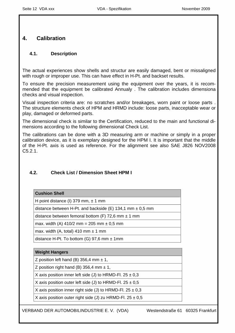
4.1. Description
The actual experiences show shells and structur are easily damaged, bent or missaligned with rough or improper use. This can have effect in H-Pt. and backset results. To ensure the precision measurement using the equipment over the years, it is recom-mended that the equipment be calibrated Annualy . The calibration includes dimensiona checks and visual inspection. Visual inspection criteria are: no scratches and/or breakages, worn paint or loose parts . The structure elements check of HPM and HRMD include: loose parts, inacceptable wear or play, damaged or deformed parts. The dimensional check is similar to the Certification, reduced to the main and functional di-mensions according to the following dimensional Check List. The calibrations can be done with a 3D measuring arm or machine or simply in a proper calibration device, as it is exemplary designed for the HPM I. It is important that the middle of the H-Pt. axis is used as reference. For the alignment see also SAE J826 NOV2008 C5.2.1.
4.2. Check List / Dimension Sheet HPM I
Weight Hangers
Z position left hand (B) 356,4 mm ± 1,
Z position right hand (B) 356,4 mm ± 1,
X axis position inner left side (J) to HRMD-Fl. 25 ± 0,3
X axis position outer left side (J) to HRMD-Fl. 25 ± 0,5
X axis position inner right side (J) to HRMD-Fl. 25 ± 0,3
X axis position outer right side (J) zu HRMD-Fl. 25 ± 0,5
Cushion Shell
H point distance (I) 379 mm, ± 1 mm
distance between H-Pt. and backside (E) 134,1 mm ± 0,5 mm
distance between femoral bottom (F) 72,6 mm ± 1 mm
max. width (A) 410/2 mm = 205 mm ± 0,5 mm
max. width (A, total) 410 mm ± 1 mm
distance H-Pt. To bottom (G) 97,6 mm ± 1mm

Seite 13 VDA xxx VDA - Spezifikation November 2009
VERBAND DER AUTOMOBILINDUSTRIE E. V. (VDA) Westendstraße 61 60325 Frankfurt
Torso Angle
torso angle at left wing (KL/KR) 90°± 0,5°
4.3. Dimension Sheet HRMD
HRMD
L) distance between weight hangers and Z probe (441mm ±0,5)
M) distance between weight hangers and backset probe (48mm ±0,3)
N) distance between weight hangers and HRMD axis in Z (148mm ±0,5)
O) distance between weight hangers and HRMD axis in X (23mm ±0,3)
P) distance between weight hangers and contact surface 25 mm ± 0,3
check and adjust level
HRMD together with HPM
backset probe scale value 80 mm ± 0,5 mm
height of Z probe 796,6 mm ± 0,5 mm
5. Perspective
A higher standard of measuring equipment will be ensured using the described activities . Several measurement comparisons have shown that the procedure SAEJ826 allows a big range of variation and interpretation. The variations will increase with less intensively trained Technicians. It is Crucial that the procedure be described in detail. Training and certification of the operators is absolutely necessary, this Process is already partially integrated.

Seite 14 VDA xxx VDA - Spezifikation November 2009
VERBAND DER AUTOMOBILINDUSTRIE E. V. (VDA) Westendstraße 61 60325 Frankfurt
6. Annex
6.1. Terminology
ASPECT-Dummy: also called HPM II dummy, initiated by the SAE HADD committee and developed by the US automotive industry to replace the HPM I. Backset: distance between headrest and head in car seats CAD: Computer Aided Design ECE: Economic Commission for Europe ECE R17: ECE’s technical regulation about seats and headrests in vehicles EuroNCAP: European New Car Assessment Program, European consumer organisation for cars FMVSS: Federal Motor Vehicle Safety Standard, safety standard of the United States for vehicles in responsibility of the NHTSA (National Highway Traffic Safety Administration) similar to ECE in Europe FMVSS202a: US safety standard about headrests in vehicles GLORIA: device to calibrate the HPM I and developed by members of the IIWPG HPM I: Hip Point Manikin of first generation also called the „Oscar“ H-Point: Hip Points are theoretical points on both sides of the pelvis that represent the axis of rotation between torso and pelvis, which refers to the axis of rotation between cushion and back of the HPM. HRP: Head Room Probe, adjustable in length and angle, mounted on the H-Pt. axis to measure head room distance and clearance between headrest and ceiling ICBC: Insurance Corporation of British Columbia, Canada IGES: Initial Graphics Exchange Specification, data standard format for CAD data exchange IIWPG: International Insurance Whiplash Prevention Group HRMD: Head Restraint Measuring Device, used together with the HPM I to measure the horizontal and vertical distance between head and headrest RONA: RONA Kinetics & Associates Ltd., Vancouver, Kanada, research and testing insti-tute for biomechanics SAE: Society of Automotive Engineers, institute of the US for standardization of vehicles and traffic technology SAEJ826 NOV2008: SAE standard, released in November 2008, describes the HPM I and the measuring procedure Thatcham: English insurance institute for vehicles Weight Hangers WH: horizontal shafts on the structure of the back of the HPM I to add torso weights and to fix the HRMD

Seite 15 VDA xxx VDA - Spezifikation November 2009
VERBAND DER AUTOMOBILINDUSTRIE E. V. (VDA) Westendstraße 61 60325 Frankfurt
Whiplash: displacement of the head together with deformation of the upper spine during a rear impact at low speed