cell selection and reselection in release 5 - dt...
TRANSCRIPT

SharpSky Focuser Construction
1st December 2012 © Dave Trewren
1
SharpSky Focuser
Construction Document
V0.12
SharpSky Focuser Construction
1st December 2012 © Dave Trewren
2
Contents
1 General .......................................................................................................................... 3
1.1 Change Record ....................................................................................................... 3
1.2 References ............................................................................................................. 3
2 Introduction .................................................................................................................... 5
3 SharpSky driver installation ............................................................................................ 5
4 List of parts included in the kit ........................................................................................ 6
5 Suggestions & fitting order for PCB ............................................................................... 7
5.1 Soldering iron & solder type .................................................................................... 7
5.2 Construction ........................................................................................................... 7
5.3 PCB build order ...................................................................................................... 7
5.4 PCB LED connections for PCB V1 .......................................................................... 8
5.5 PCB headers for PCB V1.1 ..................................................................................... 8
6 Images of the completed board & motor test connection ............................................... 9
7 Initial board test ........................................................................................................... 10
8 The main enclosure ..................................................................................................... 11
8.1 Recommended tools ............................................................................................. 11
8.2 Main enclosure holes ............................................................................................ 11
8.3 Motor enclosure holes ........................................................................................... 11
8.4 Manual control holes ............................................................................................. 12
9 LED connection ........................................................................................................... 12
10 Manual control connection ........................................................................................ 12
11 Temperature probe connection ................................................................................ 13
12 Motor & temperature probe connection .................................................................... 14

SharpSky Focuser Construction
1st December 2012 © Dave Trewren
3
1 General
1.1 Change Record
Date Version Author Reason For Change Issue
23rd
March 2012 V0.1 D.Trewren Initial version
11th April 2012 V0.2 D.Trewren Updates following user feedback
Clarified wiring section 4.4
Changed hole size section 6.4
18th April 2012 V0.3 D.Trewren Added section 3 on driver installation
20th May 2012 V0.4 D. Trewren Added section detailing headers for board
revision V1.1. Section 5.4 & 5.5
28th May 2012 V0.5 D.Trewren Updated motor header direction section 5.5
24th June 2012 V0.6 D.Trewren Added board images section 6
1st July 2012 V0.7 D.Trewren Added photo showing motor connection for initial
test section 6
30th July 2012 V0.8 D. Trewren Added details of the pre-made manual control
lead section 10
15th Sept 2012 V0.9 D. Trewren Added second set of manual control colour coding
section 10
15th Sept 2012 V0.10 D. Trewren Correct table typo in section 11
25th Nov 2012 V0.11 D. Trewren Replaced 220R resisters with 470R parts
1st Dec 2012 V0.12 D. Trewren Added colour coding for 35BYJ motor
1.2 References
Ref: Document Title Version
[1] MicroChip PIC 18F2550 datasheet

SharpSky Focuser Construction
1st December 2012 © Dave Trewren
4

SharpSky Focuser Construction
1st December 2012 © Dave Trewren
5
2 Introduction
The Purpose of this document is to give detailed instructions and suggestion regarding the construction of the SharpSky focuser kit. The kit contains all of the components required to build a stepper motor based digital focuser.
The project consists of the following hardware component parts :
- Main control box containing all the electronics including the PIC microprocessor
- The motor housing (contained the motor & optional temperature sensor)
- The manual controller
- The temperature sensor & connector
The project consists of the following software/firmware components :
- PIC microprocessor resident bootloader
- PIC microprocessor resident firmware
- PC resident ASCOM driver
- PC resident client
- PC resident bootloader client
3 SharpSky driver installation
I am discussing this topic before the build detail just so it doesn’t get missed at the end. Correct driver installation is critical to the correct operation of the focuser under PC control.
Driver installation is as follows :
- Ensure you have the latest ASCOM 6SP1 platform installed. This is especially important if your PC is running a 64bit operating system.
- Before installing the driver ensure all ASCOM clients (Maxim DL, ImagesPlus etc ..) applications are closed. This is especially important if you are installing a driver update with a previous version already installed.
- Execute the SharpSky driver installer but double clicking on ‘SharpSky Setup.exe’ once downloaded from the website.

SharpSky Focuser Construction
1st December 2012 © Dave Trewren
6
4 List of parts included in the kit
Component No Component No
SharpSky custom PCB 1 PIC18F2550 microcontroller 1
28pin turned pin IC socket 1 SharpSky firmware 1
16pin turned pin IC socket 1 SharpSky bootloader 1
4MHz crystal 1 ULN2003A Darlington driver 1
USB-B socket 1 78L05 voltage regulator 1
Mini DIN 3 pin socket 1 10uF electrolytic capacitor 2
Mini DIN 4 pin socket 1 220nF capacitor 2
Mini DIN 3 pin plug 1 22pF capacitor 2
Mini DIN 4 pin plug 1 1N4001 diode 1
D-type male 9 pin 1 Bright red LED 5
D-type female 9 pin * 1 1k resistor 1
D-type 9 pin male to female cable * 1 10k resistor 1
Power socket/plug (5mm x 2.1mm) 1 470R resistor 1
Stepper motor * 1 10k common mode resistor pack 1
Digital temperature sensor 1 470R isolated mode resistor pack 1
Beam coupler * 1
Rotary encoder 1
Main enclosure 1
Manual enclosure + 4 core cable 1
Motor enclosure * 1
Manual control knob 1
(*) component not present in controller only kit

SharpSky Focuser Construction
1st December 2012 © Dave Trewren
7
5 Suggestions & fitting order for PCB
5.1 Soldering iron & solder type
I suggest a medium power soldering iron 20-25W with a relatively small bit fitted. The solder used is very important and makes all the difference in terms of ease of soldering and joint quality. Use a medium thickness solder 1-2mm thickness with a pre fluxed core.
5.2 Construction
1. The 28 & 16 pin IC sockets will tend to absorb solder, it will collect on the socket side of the board eventually bridging to the adjacent pin. Only use a small amount of solder, not more than 1cm per pin.
2. Some connections have unrelated through board via holes in close proximity. Avoid solder bridges between connections and via points.
3. Care should be taken when inserting the PIC and Darlington driver IC’s into their respective sockets. Bend the IC pins together on a flat surface so that they align with the socket holes. Make sure all pins are aligned with the socket hole centres before inserting – do not force, as this may result in a misaligned pin buckling rather than being inserted.
4. When soldering PCB mounted connectors apply only enough solder to the mounting pins to fill the mounting hole. There is a gap around the pin but the holes are through hole plated and the solder will readily bridge the gap.
5.3 PCB build order
IMPORTANT - all components marked with a ‘*’ must be fitted with the correct polarity or orientation. This generally applies to semiconductors, electrolytic capacitors & diodes, for SharpSky also apply to common mode resister pack R4.
28 pin PIC IC socket
16 pin Darlington driver socket
78L05 voltage regulator (note 1) *
D1 reverse polarity protection diode *
Capacitors C1 & C2 (10uF) *
Capacitors C3 & C6 (220nF)
Capacitors C4 & C5 (22pF)
Resistors R1, R2 & R3 (1k, 10k & 470R)
Resistor pack R6 board marking ‘LED limit’ (470R)
Resistor pack R4 board marking ‘Pull Up’ (10k) *
(the pack is orientated such that the end marker dot is towards the
board centre, closest to the adjacent R6 pack)
D2 heart beat LED (long leg is +, see board marking) *
SharpSky Focuser Construction
1st December 2012 © Dave Trewren
8
X1 4MHz crystal
USB connector
Mini DIN 3-pin
Mini DIN 4-pin
Power socket
D-type connector (screw into place before soldering)
Insert PIC microprocessor, pin 1 facing the PCB ‘PIC’ label. Insert the
Darlington driver, pin 1 facing the PCB ‘Driver’ label.
Note 1 : The 78L05 pin pitch is very tight. I suggest soldering the centre pin first and then the two pins either side to minimise the chance of creating a solder bridge.
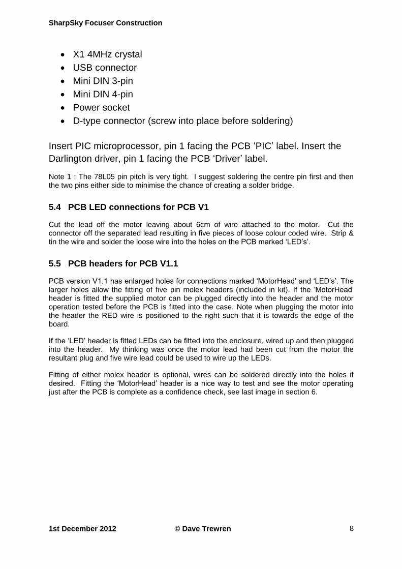
5.4 PCB LED connections for PCB V1
Cut the lead off the motor leaving about 6cm of wire attached to the motor. Cut the connector off the separated lead resulting in five pieces of loose colour coded wire. Strip & tin the wire and solder the loose wire into the holes on the PCB marked ‘LED’s’.
5.5 PCB headers for PCB V1.1
PCB version V1.1 has enlarged holes for connections marked ‘MotorHead’ and ‘LED’s’. The larger holes allow the fitting of five pin molex headers (included in kit). If the ‘MotorHead’ header is fitted the supplied motor can be plugged directly into the header and the motor operation tested before the PCB is fitted into the case. Note when plugging the motor into the header the RED wire is positioned to the right such that it is towards the edge of the board.
If the ‘LED’ header is fitted LEDs can be fitted into the enclosure, wired up and then plugged into the header. My thinking was once the motor lead had been cut from the motor the resultant plug and five wire lead could be used to wire up the LEDs.
Fitting of either molex header is optional, wires can be soldered directly into the holes if desired. Fitting the ‘MotorHead’ header is a nice way to test and see the motor operating just after the PCB is complete as a confidence check, see last image in section 6.

SharpSky Focuser Construction
1st December 2012 © Dave Trewren
9
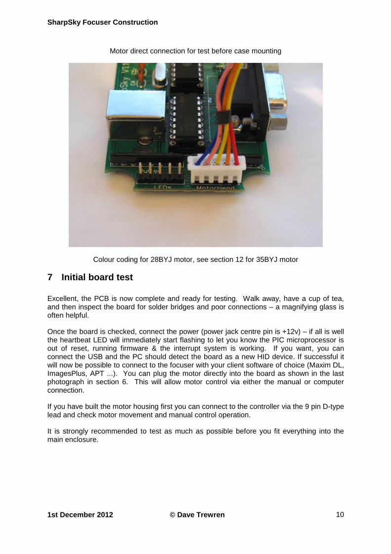
6 Images of the completed board & motor test connection
Top component layer 1 of PCB
Bottom track layer 2 of PCB
SharpSky Focuser Construction
1st December 2012 © Dave Trewren
10
Motor direct connection for test before case mounting
Colour coding for 28BYJ motor, see section 12 for 35BYJ motor
7 Initial board test
Excellent, the PCB is now complete and ready for testing. Walk away, have a cup of tea, and then inspect the board for solder bridges and poor connections – a magnifying glass is often helpful.
Once the board is checked, connect the power (power jack centre pin is +12v) – if all is well the heartbeat LED will immediately start flashing to let you know the PIC microprocessor is out of reset, running firmware & the interrupt system is working. If you want, you can connect the USB and the PC should detect the board as a new HID device. If successful it will now be possible to connect to the focuser with your client software of choice (Maxim DL, ImagesPlus, APT ...). You can plug the motor directly into the board as shown in the last photograph in section 6. This will allow motor control via either the manual or computer connection.
If you have built the motor housing first you can connect to the controller via the 9 pin D-type lead and check motor movement and manual control operation.
It is strongly recommended to test as much as possible before you fit everything into the main enclosure.

SharpSky Focuser Construction
1st December 2012 © Dave Trewren
11
8 The main enclosure
The main case has been marked but not drilled out. I would suggest the following procedures and tools.
8.1 Recommended tools
1. Several different size holes are required. For drilling soft plastic cases I generally use a tapered drill bit. These are available on eBay for less than ten pounds and are really useful for any type of plastic or aluminium enclosure work.
2. A set of needle files is also really useful and can also be bought on-line very cheaply.
3. A small pair of nose pliers is very useful for fiddly bits such as holding wire while soldering (it gets hot very quickly)
8.2 Main enclosure holes
1. For the mini DIN connectors drill 12.5mm holes.
2. For the power socket drill an 8mm hole.
3. For the USB connector drill a centre hole and then use needle files to create the square profile.
4. For the D-type drill three holes in a line and then use needle files to create the rectangular profile.
Once you are happy with the PCB operation, fit the board into the main enclosure. Push the PCB down onto the mounting posts until the post ends are level with the surface of the PCB. Check all the connectors line up with their respective enclosure holes. Once happy screw the 3mm CSK screws into the mounting posts to secure the PCB. Do not over tighten the CSK screws as they may start to mark the rear of the enclosure.
NOTE : fit the PCB into the main enclosure ‘before’ inserting the LED’s
4. For the LED’s drill 4.5mm holes. Insert the LED housings from the case outside and hold in position with your finger. Insert the LED from the case inside, holding the part with nose pliers and inserting into the housing until the LED clicks into position.
8.3 Motor enclosure holes
1. For the motor drive shaft drill a 10mm hole.
2. For the motor mounting drill 4mm holes.
3. For the D-type drill three holes in a line and the use needle files to create the rectangular profile.
Note : The position of the D-type is arbitrary and a suitable position should be chosen to suit your particular scope setup such that the connector and lead do not foul the mount or scope.

SharpSky Focuser Construction
1st December 2012 © Dave Trewren
12
8.4 Manual control holes
1. For the rotary encoder remove the location tab and drill an 6mm hole.
2. For the manual control cable drill a 4mm hole.
9 LED connection
There are four case mounted LED’s. The ‘long leg’ of all the LED’s is wired together and forms the common. This results in five connections to the PCB. You have already fitted the five coloured wires to the PCB and so can now wire up the LED’s fitted to the enclosure.
Looking at the PCB with LED connection strip facing down (see below) you can see the five LED connection holes with LED’s written below the line of holes.
1 2 3 4 5
LED’s 1. USB status
2. Manual control
3. Direction +
4. Direction –
5. Common (long LED legs)
10 Manual control connection
Referencing the rear of the rotary encoder and the rear solder side of the 4 pin mini DIN. The mini DIN plastic sleeve may require a drop of epoxy to prevent the sleeve slipping off when the plug is removed.
Rotary Encoder 4 pin mini DIN
1 2 3 1 2
4 5 3 4
LOC PIN
SharpSky Focuser Construction
1st December 2012 © Dave Trewren
13
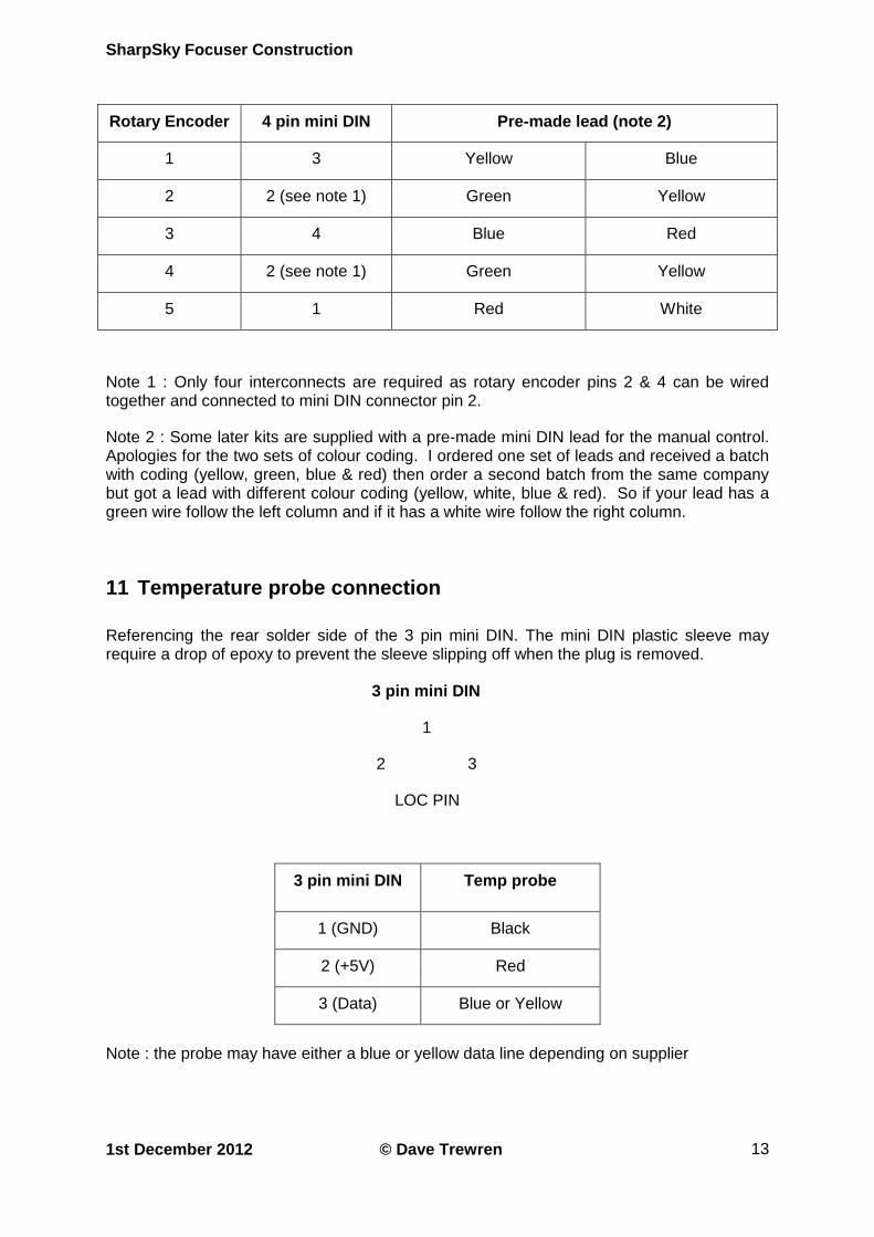
Rotary Encoder 4 pin mini DIN Pre-made lead (note 2)
1 3 Yellow Blue
2 2 (see note 1) Green Yellow
3 4 Blue Red
4 2 (see note 1) Green Yellow
5 1 Red White
Note 1 : Only four interconnects are required as rotary encoder pins 2 & 4 can be wired together and connected to mini DIN connector pin 2.
Note 2 : Some later kits are supplied with a pre-made mini DIN lead for the manual control. Apologies for the two sets of colour coding. I ordered one set of leads and received a batch with coding (yellow, green, blue & red) then order a second batch from the same company but got a lead with different colour coding (yellow, white, blue & red). So if your lead has a green wire follow the left column and if it has a white wire follow the right column.
11 Temperature probe connection
Referencing the rear solder side of the 3 pin mini DIN. The mini DIN plastic sleeve may require a drop of epoxy to prevent the sleeve slipping off when the plug is removed.
3 pin mini DIN
1
2 3
LOC PIN
3 pin mini DIN Temp probe
1 (GND) Black
2 (+5V) Red
3 (Data) Blue or Yellow
Note : the probe may have either a blue or yellow data line depending on supplier
SharpSky Focuser Construction
1st December 2012 © Dave Trewren
14
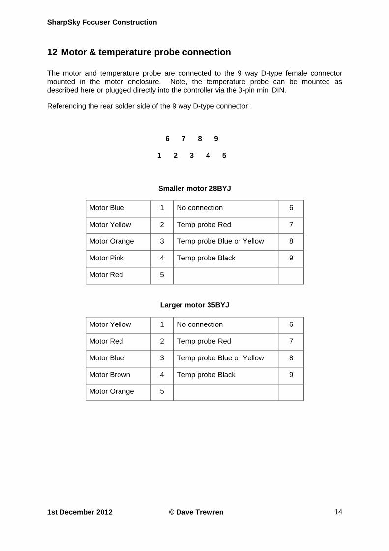
12 Motor & temperature probe connection
The motor and temperature probe are connected to the 9 way D-type female connector mounted in the motor enclosure. Note, the temperature probe can be mounted as described here or plugged directly into the controller via the 3-pin mini DIN.
Referencing the rear solder side of the 9 way D-type connector :
6 7 8 9
1 2 3 4 5
Smaller motor 28BYJ
Motor Blue 1 No connection 6
Motor Yellow 2 Temp probe Red 7
Motor Orange 3 Temp probe Blue or Yellow 8
Motor Pink 4 Temp probe Black 9
Motor Red 5
Larger motor 35BYJ
Motor Yellow 1 No connection 6
Motor Red 2 Temp probe Red 7
Motor Blue 3 Temp probe Blue or Yellow 8
Motor Brown 4 Temp probe Black 9
Motor Orange 5