ce6311 survey practical i lab manual
TRANSCRIPT

SHREENIVASA ENGINEERING COLLEGE
Approved by AICTE and Affiliated to Anna University B.Pallipatti, Bommidi, Pappireddipatti (TK), Dharmapuri – 635 301
DEPARTMENT OF CIVIL ENGINEERING
CE6311 – SURVEY PRACTICAL I
LAB MANUAL
Prepared by G.Kumareshan/Lect/Civil
www.Vidyarthiplus.com
www.Vidyarthiplus.com

CE6311 – SURVEY PRACTICAL I
LIST OF EXPERIMENTS
1. Study of chains and its accessories.
2. Aligning, Ranging and Chaining.
3. Chain Traversing.
4. Compass Traversing.
5. Plane Table Surveying: Radiation.
6. Plane Table Surveying: Intersection.
7. Plane Table Surveying: Traversing.
8. Plane Table Surveying: Resection – Three point
problem.
9. Plane Table Surveying: Resection – Two point
problem.
10. Study of levels and leveling staff.
11. Fly leveling using Dumpy level.
12. Fly leveling using tilting level.
13. Check leveling.
14. LS and CS.
15. Contouring.
16. Study of Theodolite.
www.Vidyarthiplus.com
www.Vidyarthiplus.com

INDEX
Ex.No
Date
Name of the Experiment
Marks
Signature
of Staff
CHAIN SURVEY
1 Study of Chains and Its accessories 2 Aligning, Ranging and Chaining of a
line
3 (a) Chain Traversing – Determination of the area of the given boundary with respect to a point
3 (b) Chain Traversing – Determination of the area of the given boundary with respect to base line
COMPASS SURVEY
4 Compass Traversing – Closed Traversing
PLANE TABLE SURVEY 5 Plane Table Survey – Radiation
Method
6 Plane Table Survey – Intersection Method
7 Plane Table Survey – Closed Traversing Method
8 Plane Table Survey – Resection: Three Point Problem
9 Plane Table Survey – Resection: Two Point Problem
LEVELLING
10 Study of Levels and Leveling Staff 11 Fly leveling Using Dumpy Level
12 Check leveling using Dumpy level 13 Longitudinal and Cross sectional
leveling along a road
THEODOLITE SURVEY
14 Study of Theodolite
www.Vidyarthiplus.com
www.Vidyarthiplus.com

2 ALIGNING, RANGING AND CHAINING OF A LINE
Aim
To measure the distance between two points on a level ground by
aligning, ranging and chaining.
Instrument Required
1. Chain
2. Ranging Rod
3. Arrows
4. Cross staff
5. Pegs
Procedure
1. Fix the ranging rods at the given two points, where pegs are already
driven on the ground.
2. The follower stands behind station A and direct the leader with
ranging rod to come in line with AB.
3. By signals of ranging, when the ranging rod comes in the line of AB the
follower direct the leader to fix ranging rod.
4. Let the intermediate point C which should be less than 30 m. Now, the
leader takes another rod and stand between A and B about 2/3
distance from A.
5. The follower directs the leader to come line of AB by using signals of
ranging, as and when the follower direct to fix the ranging rod
position.
6. Let another intermediate point D, which is less than 30 m from B. Now
A, B, C and D are in one line. Now the leader and follower measure the
distance.
Result
The distance between A and B =
www.Vidyarthiplus.com
www.Vidyarthiplus.com
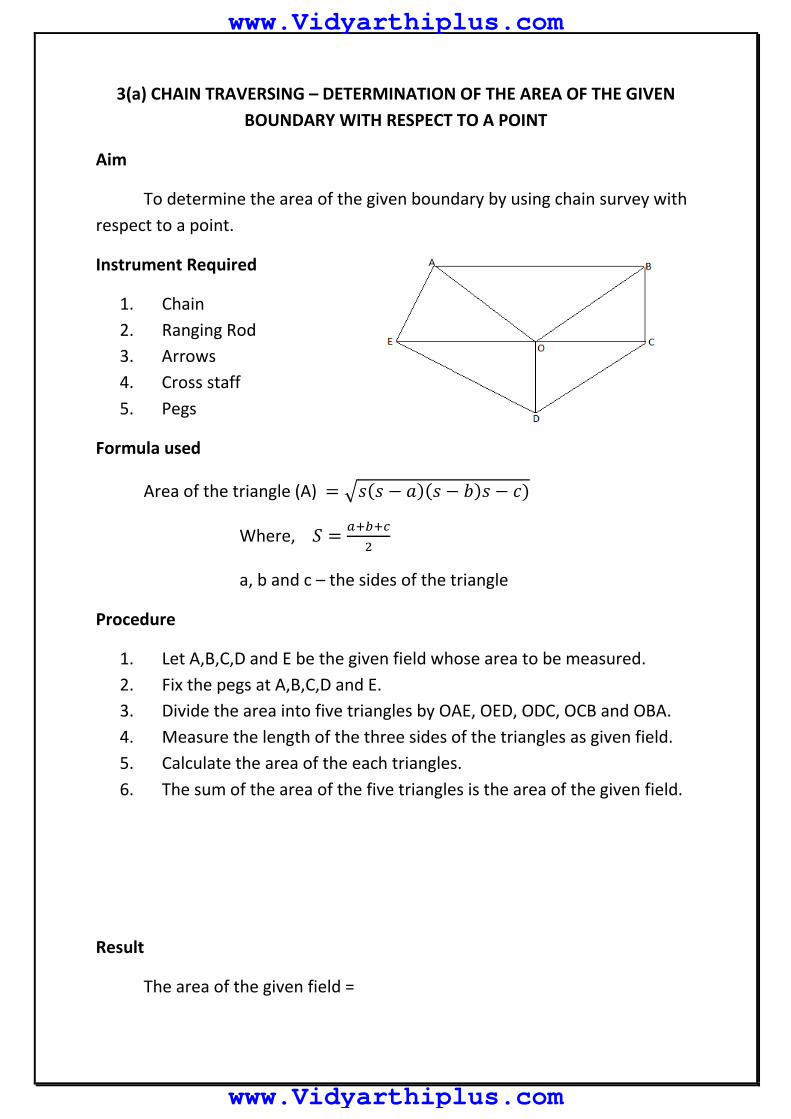
3(a) CHAIN TRAVERSING – DETERMINATION OF THE AREA OF THE GIVEN
BOUNDARY WITH RESPECT TO A POINT
Aim
To determine the area of the given boundary by using chain survey with
respect to a point.
Instrument Required
1. Chain
2. Ranging Rod
3. Arrows
4. Cross staff
5. Pegs
Formula used
Area of the triangle (A) = √𝑠(𝑠 − 𝑎)(𝑠 − 𝑏)𝑠 − 𝑐)
Where, 𝑆 =𝑎+𝑏+𝑐
2
a, b and c – the sides of the triangle
Procedure
1. Let A,B,C,D and E be the given field whose area to be measured.
2. Fix the pegs at A,B,C,D and E.
3. Divide the area into five triangles by OAE, OED, ODC, OCB and OBA.
4. Measure the length of the three sides of the triangles as given field.
5. Calculate the area of the each triangles.
6. The sum of the area of the five triangles is the area of the given field.
Result
The area of the given field =
www.Vidyarthiplus.com
www.Vidyarthiplus.com

3(b) CHAIN TRAVERSING – DETERMINATION OF THE AREA OF THE GIVEN
BOUNDARY WITH RESPECT TO A BASE LINE
Aim
To determine the area of the given boundary by using chain survey with
respect to a base line.
Instrument Required
1. Chain
2. Ranging Rod
3. Arrows
4. Cross staff
5. Pegs
Formula used
Area of the triangle (A) =1
2𝑏ℎ
Area of the trapezoidal (A) =1
2(𝑎 + 𝑏)ℎ
Procedure
1. Let A,B,C,D,E and F be the given field whose area to be measured.
2. Fix the pegs at the A,B,C,D,E and F.
3. To select the base line which is visible.
4. To locate the perpendicular offset by using cross staff at required
stations.
5. To split the given area into number of triangles and trapezoids.
6. Measure the length of the sides of the triangles and trapezoids.
7. Calculate the area of the each triangles and trapezoids.
8. The sum of the area of all the triangles and trapezoids gives the area
of the given field.
Result
The area of the given field =
www.Vidyarthiplus.com
www.Vidyarthiplus.com

4 COMPASS TRAVERSING – CLOSED TRAVERSING
Aim
To conduct compass survey along the closed traverse.
Instrument Required
1. Prismatic compass
2. Chain or Tape
3. Ranging rods
4. Pegs or arrows
Formula used
Included angle = Back bearing of previous line – Fore bearing of next line
Check
The sum of the included angles should be equals to (2n-4)900
Where, n – number of sides of the traverse
Procedure
1. Fix the closed traverse A B C D E.
2. Setup the compass at the station A.
3. Perform the temporary adjustment.
4. View the object at B and note down the fore bearing (FB) of the line
AB and measure the distance.
5. View the object at E and note down the back bearing (BB) of the line
EA.
6. Shift the instrument to station ‘B’ performs all the temporary
adjustments.
7. Sight the object at ‘A’ and take the ‘BB’ of ‘AB’.
8. Take ‘FB’ of ‘BC’ and measure the length of ‘BC’.
9. Check whether the difference of ‘FB’ and ‘BB’ is 180º or not, at all
stations.
10. Continue the same process all at other stations.
www.Vidyarthiplus.com
www.Vidyarthiplus.com

Observations & Table
S.No STATION LINE LENGTH (m) ANGLE
1 A AB AE
2 B BA
BC 3 C CB
CD 4 D DC
DE 5 E ED
EA
Result
The amount of closing error =
www.Vidyarthiplus.com
www.Vidyarthiplus.com

5 PLANE TABLE SURVEYING – RADIATION METHOD
Aim
Setting up the plane table and plotting a few object by radiation method.
Instrument Required
1. Plane table
2. Tripod
3. Alidade
4. Plumb bob with fork
5. Trough compass
6. Sprit level
Formula used
Area of the triangle (A) = √𝑠(𝑠 − 𝑎)(𝑠 − 𝑏)𝑠 − 𝑐)
Where, 𝑆 =𝑎+𝑏+𝑐
2
a, b and c – the sides of the triangle
Procedure
1. Select a point “O “so that all points to be located are visible from it.
2. Set up the table at “O”, level it, and do centring.
3. Select a point “O” on the sheet so that it is exactly over station “O” on
the ground.
4. Mark the direction of the magnetic meridian.
5. Centring the alidade on “O” bisect the objects of traverse A, B, C, D
and E.
6. Measure the distances OA, OB, OC, OD and OE plotted to convenient
scale to locate a, b, c, d and e respectively
7. Join the points a, b, c, d and e on the paper.
Result
The outside of the profile is plotted.
The boundary area =
www.Vidyarthiplus.com
www.Vidyarthiplus.com

6 PLANE TABLE SURVEYING – INTERSECTION METHOD
Aim
To plot different field objects by using intersection method.
Instrument Required
1. Plane table
2. Tripod
3. Alidade
4. Plumb bob with fork
5. Trough compass
6. Sprit level
7. Ranging rods
8. Pegs or arrows
Procedure
1. Set the table at A, level it and transfer the point A on the sheet by way of plumbing fork. Clamp the table.
2. With the help of the trough compass, mark the north direction on the sheet.
3. Pivoting the alidade about a, sight it to B. Measure AB and plot it along the ray to get b. The base line ab is thus drawn.
4. Pivoting the alidade at a, sight the details C, D, E, F, G and draw corresponding rays.
5. Shift the table at B and set it there. Orient the table roughly by compass and finally by back sighting A.
6. Pivoting the alidade about b, sight the details C, D, E etc. and draw the corresponding rays along the edge of the alidade to intersect with the previously drawn rays in c, d, e etc.
7. The positions of the points are thus mapped by way of intersection.
Result
The outside of the profile is plotted.
www.Vidyarthiplus.com
www.Vidyarthiplus.com

7 PLANE TABLE SURVEYING – CLOSED TRAVERSING
Aim
To run survey lines between various field object by closed traversing
with using plane table surveying.
Instrument Required
1. Plane table
2. Tripod
3. Alidade
4. Plumb bob with fork
5. Trough compass & Sprit level
6. Tape
7. Ranging rods
8. Pegs or arrows
Formula used
Area of the triangle (A) = √𝑠(𝑠 − 𝑎)(𝑠 − 𝑏)𝑠 − 𝑐)
Where, 𝑆 =𝑎+𝑏+𝑐
2
a, b and c – the sides of the triangle
Procedure
1. Set the table at A. Use plumbing fork for transferring A on to the sheet. Draw the direction of magnetic meridian with the help of trough compass.
2. With the alidade pivoted about a, sight it to B and draw the ray. Measure AB and scale off ab to some scale. Similarly draw a ray towards E, measure AE and plot e.
3. Shift the table to B and set it. Orient the table accurately by back sighting A. Clamp the table.
4. Pivoting the alidade about b, sight to C. Measure BC and plot it on the drawn ray to the same scale. Similarly, the table can be set at other stations and the traverse is completed.
Result
The outline of the profile is plotted and the boundary area is =
www.Vidyarthiplus.com
www.Vidyarthiplus.com

8 PLANE TABLE SURVEYING – RESECTION: THREE POINT PROBLEM
Aim
Determine the instrument station by three point problem method using
graphical method.
Instrument Required
1. Plane table
2. Tripod
3. Alidade
4. Plumb bob with fork
5. Trough compass
6. Sprit level
7. Tape
8. Ranging rods
9. Pegs
10. Arrows
Procedure
1. Let A, B, C be the known points and a, b, c be their plotted positions. Let P be the position of the instrument station to be located on the map.
2. Set the table on P. Orient the table approximately with eye so that ‘ab’ is parallel to AB.
3. Draw a line ‘ae’ perpendicular to ‘ab’ at a. Keep the alidade along ‘ea’ and rotate the plane table till A is bisected. Clamp the table. With b as centre, direct the alidade to sight B and draw the ray ‘be’ to cut ‘ae’ in e.
4. Similarly, draw ‘cf’ perpendicular to ‘bc’ at c. Keep the alidade along ‘fc’ and rotate the plane table till C is bisected. Clamp the table. With b as centre, direct the alidade to sight B and draw the ray ‘bf’ to cut ‘cf’ in f.
5. Join e and f. Using set square, draw ‘bp’ perpendiculat to ‘ef’. Then p represents on the plan the position P of the table on the ground.
6. To orient the table, keep the alidade along ‘pb’ and rotate the plane table till B is bisected. To check the orientation draw rays aA, cC both of which should pass through p.
www.Vidyarthiplus.com
www.Vidyarthiplus.com

Result
The instrument station P is plotted in the sheet has p using plane table
three point problem method (Graphical method)
www.Vidyarthiplus.com
www.Vidyarthiplus.com

9 PLANE TABLE SURVEYING – RESECTION: THREE POINT PROBLEM
Aim
Determine the instrument station by three point problem method using
graphical method.
Instrument Required
1. Plane table
2. Tripod
3. Alidade
4. Plumb bob with fork
5. Trough compass
6. Sprit level
7. Tape
8. Ranging rods
9. Pegs
10. Arrows
Procedure
1. Let us take two points A and B, the plotted positions of which are known. Let C be the point to be plotted. The whole problem is to orient the table at C.
2. Choose an auxiliary point D near C, to assist the orientation at C. Set the table at D in such a way that ‘ab’ is approximately parallel to ‘AB’ (either by compass or by eye judgement). Clamp the table.
3. Keep the alidade at ‘a’ and sight A. Draw the resector. Similarly, draw a resector from b and B to intersect the previous one in d. The position of d is thus got, the degree of accuracy of which depends upon the approximation that has been made in keeping ‘ab, parallel to AB. Transfer the point d to the ground and drive a peg.
4. Keep the alidade at d and sight C. Draw the ray. Mark a point c1 on the ray by estimation to represent the distance DC.
5. Shift the table to C, orient it (tentatively) by taking back sight to D and centre it with reference to c1. The orientation is thus, the same as it was at D.
6. Keep the alidade pivoted at ‘a’ and sight it to A. Draw the ray to intersect with previously drawn ray from D in c. Thus, c is the point
www.Vidyarthiplus.com
www.Vidyarthiplus.com

representing the station C, with reference to the approximate orientation made at D.
7. Pivoting the alidade about c, sight B. Draw the ray to intersect with the ray drawn from D to B in b’. Thus b’ is the approximate representation if B with respect to the orientation made at D.
8. The angle between ab and ab’ may coincide (or may become parallel) keep a pole P in line with ab’ and at a great distance. Keeping the alidade along ab, rotate the table till P is bisected. Clamp the table. The table is thus correctly oriented.
9. After having oriented the table as above, draw a resector from a to A and another from b to B, the intersection of which will give the position C occupied by the table.
Result
The instrument station C is plotted in the sheet has ‘c’ using plane table
two point problem method.
www.Vidyarthiplus.com
www.Vidyarthiplus.com

11 FLY LEVELING USING DUMPY LEVEL
Aim
To determine the elevations and level difference between the given
points.
Instrument Required
1. Dumpy level
2. Leveling staff
3. Plumb bob
4. Arrows
Procedure
1. To set up the instrument at a convenient point and do all the initial adjustments.
2. To direct the telescope towards the first point (Bench Mark) and enter the reading as back sight (BS).
3. To enter the reading of the last visible point from the instrument stations as fore sight (FS) and of all the other points as intermediate stations (IS).
4. Similarly do the same procedure for other three change points.
www.Vidyarthiplus.com
www.Vidyarthiplus.com

Observations & Table
(I) Height of collimation method HI = RL + BS
STATION BS IS FS HI RL REMARKS 1
2 3
4
5 6
7 8
9 10
11
12 13
Calculations
Last RL – First RL = ∑BS - ∑FS
www.Vidyarthiplus.com
www.Vidyarthiplus.com

(II) Rise and Fall method
STATION BS IS FS RISE FALL RL REMARKS 1
2 3
4
5 6
7 8
9 10
11
12 13
Calculations
Last RL – First RL = ∑BS - ∑FS = ∑RISE - ∑FALL
Result
The level difference between consecutive points are calculated.
www.Vidyarthiplus.com
www.Vidyarthiplus.com

12 CHECK LEVELING USING DUMPY LEVEL
Aim
To determine the elevations and level difference between the given
points.
Instrument Required
1. Dumpy level
2. Leveling staff
3. Plumb bob
4. Arrows
Procedure
1. To set up the instrument at a convenient point and do all the initial adjustments.
2. To direct the telescope towards the first point (Bench Mark) and enter the reading as back sight (BS).
3. To enter the reading of the last visible point from the instrument stations as fore sight (FS) and of all the other points as intermediate stations (IS).
4. Similarly do the same procedure for other three change points.
www.Vidyarthiplus.com
www.Vidyarthiplus.com

Observations & Table
(I) Height of collimation method HI = RL + BS
STATION BS IS FS HI RL REMARKS 1
2 3
4
5 6
7 8
9 10
11
12 13
14 15
16
17 18
19 20
21 22
23
24
Calculations
Last RL – First RL = ∑BS - ∑FS
www.Vidyarthiplus.com
www.Vidyarthiplus.com

(II) Rise and Fall method
STATION BS IS FS RISE FALL RL REMARKS 1
2 3
4
5 6
7 8
9 10
11
12 13
14 15
16
17 18
19 20
21 22
23
24
Calculations
Last RL – First RL = ∑BS - ∑FS = ∑RISE - ∑FALL
Result
The level difference between consecutive points are calculated.
www.Vidyarthiplus.com
www.Vidyarthiplus.com

13 LONGITUDINAL AND CROSS SECTIONAL LEVELING ALONG A ROAD
Aim
To plot the longitudinal section and cross section of the given road using
the method of fly leveling.
Instrument Required
1. Leveling staff
2. Leveling instrument (Dumpy level)
3. Ranging rods
4. Cross staff
5. Chain
6. Tape
7. Pegs
8. Arrows
Longitudinal section
The operation of taking level along the center lines if any augments at
regular intervals is known as longitudinal leveling. Back sight, intermediate
sight and fore sight are taken at regular intervals at every setup of the
instrument to the nature of the ground surface.
Cross section
The operation of taking level along the transverse direction of the
longitudinal leveling. The cross sectional leveling is taken at regular interval
along the augment.
Procedure
1. The instrument was setup along the side of the road and the necessary adjustments were made.
2. Then the bench mark is fixed by sighting the instrument on any permanent structures.
3. The width of the road is measured and the staff is held at the midway of proposed road.
4. The central hair reading is noted down, then the staff is shifted to the right and the left side and the reading is recorded.
www.Vidyarthiplus.com
www.Vidyarthiplus.com

5. Similarly the same procedure is carried out by keeping the staff at regular intervals.
6. Then the reduce levels of the offsets were calculated and the profile is shown in the graph.
www.Vidyarthiplus.com
www.Vidyarthiplus.com

Observations & Table
Height of collimation method HI = RL + BS
STATION BS IS FS HI RL REMARKS 1
2 3
4
5 6
7 8
9 10
11
12 13
14 15
16
17 18
19 20
21 22
23
24 25
26
27
28
29 30
31 32
34 35
36
www.Vidyarthiplus.com
www.Vidyarthiplus.com

STATION BS IS FS HI RL REMARKS
37 38
39 40
41 42
43
44 45
46 47
48
49 50
51 52
53 54
55
Calculations
Last RL – First RL = ∑BS - ∑FS
Result
The reduced level of various points along the cross section and
longitudinal section are determined and the graph is plotted to the scale.
www.Vidyarthiplus.com
www.Vidyarthiplus.com