ce-100 section rolls
TRANSCRIPT
0
USE AND MAINTENANCE INSTRUCTIONMANUAL
( Rev.0.0 15/05/02)
CCEE 110000
WARNING !!Any use of the machine that does not conform with what is expressly written in
this document immediately frees the MANUFACTURER from anyresponsibility or warranty obligation.
NOTES: Carefully read this instruction manual before installing andstarting the machine.
DIRECTIVE 98/37/EC
“MACHINE DIRECTIVE”
Presidential Decree. 459/96
Directive 98/37/EC – published on theEuropean community Official Journalnr. L 207 of July 23, 1998.
Presidential decree 459/96 – publishedon the Official Journal nr. 209 ofSeptember 06, 1996
CML International S.p.A. Instruction Manual
1
INDEX
CE 100 ROLLER BENDER DESCRIPTION ....................................................................................................................4Main components identification.......................................................................................................4
WARRANTY .....................................................................................................................................................................5Warranty conditions and restrictions: ..............................................................................................5
MACHINE TRANSPORTATION .....................................................................................................................................6Lifting from bottom with packing....................................................................................................6Lifting from bottom without packing...............................................................................................6Packing methods ..............................................................................................................................6Lifting from top................................................................................................................................7Machine vertical/horizontal positioning...........................................................................................7Transportation on road using authorized mean ................................................................................7
SAFETY NORMS ..............................................................................................................................................................8Overview ..........................................................................................................................................8Active safety.....................................................................................................................................8
Command system .........................................................................................................................8Passive safety ...................................................................................................................................8
Prescriptions........................................................................................................................................................................9Machine equipment...........................................................................................................................................................11
Standard equipment:.......................................................................................................................11Optional accessories.......................................................................................................................11
BENDING CAPACITY....................................................................................................................................................12Bending suggestions .........................................................................................................................................................13
Overview ........................................................................................................................................13Main parameters that may influence bending: ...............................................................................13Standard multipurpose rolls ...........................................................................................................13
ROLLS ARRANGEMENT ..............................................................................................................................................14“RECTANGULAR SOLID HARD WAY” Bending ....................................................................14“SQUARE SOLID” Bending .........................................................................................................14“SQUARE TUBE” Bending ..........................................................................................................15“RECTANGULAR TUBE EASY WAY” Bending.......................................................................15“RECTANGULAR TUBE HARD WAY” ....................................................................................15“ANGLE LEG OUT”.....................................................................................................................16Solution for distortion problem when bending profiles .................................................................16“ANGLE LEG OUT”:....................................................................................................................16“ANGLE LEG IN” Bending ..........................................................................................................17Solution for distortion problem when bending profiles .................................................................17“ANGLE LEG IN”.........................................................................................................................17Operations needed to avoid distortion:...........................................................................................17“T LEG OUT”/...............................................................................................................................17“T LEG IN”....................................................................................................................................17
“ ANGLE LEG IN “ RING ROLLING ............................................................................................................................18“T LEG UP” Bending ....................................................................................................................22“C LEG OUT” Bending .................................................................................................................22“C LEG IN” Bending .....................................................................................................................22“BEAM HARD WAY” Bending ...................................................................................................23 “ROUND TUBES” Bending.........................................................................................................23“ROUND SOLID” Bending...........................................................................................................23
Side rolls adjustment.........................................................................................................................................................24Adjustment Operations...................................................................................................................24
Machine Preparation .........................................................................................................................................................25
CML International S.p.A. Instruction Manual
2
Electrical connection ..................................................................................................................... 25Electrical panel .......................................................................................................................... 25
Electrical panel topographical diagram ......................................................................................... 26Connection................................................................................................................................. 26
Hydraulic power unit ..................................................................................................................... 26Troubleshooting ............................................................................................................................................................... 27
Overview........................................................................................................................................ 27Maintenance ..................................................................................................................................................................... 29
Lubrication..................................................................................................................................... 29Bearings ..................................................................................................................................... 29
Hydraulic power unit ..................................................................................................................... 30Checking oil level ...................................................................................................................... 30Refilling ..................................................................................................................................... 30Discharges.................................................................................................................................. 30Changing oil............................................................................................................................... 31
Gear motors...................................................................................................................................................................... 32Cleaning ........................................................................................................................................................................... 32
Overview........................................................................................................................................ 32Machine cleaning........................................................................................................................... 32
Risk prevention solutions ................................................................................................................................................. 33Machine stop operations ................................................................................................................ 33Risks due to fall or projection of bent part .................................................................................... 33Operator’s Position ........................................................................................................................ 35Left to right bending ...................................................................................................................... 35
Tags / Plates ..................................................................................................................................................................... 36Safety signals ................................................................................................................................. 36Identification Plate CE marking .................................................................................................... 36
Working speed ................................................................................................................................................................. 37Scraps disposal ................................................................................................................................................................. 38
Machine demolition ....................................................................................................................... 38Ecological information .................................................................................................................. 38Indications for correct waste disposal............................................................................................ 38
Technical tables................................................................................................................................................................ 39Technical data tables...................................................................................................................... 39Dimensions Table .......................................................................................................................... 39Weights Table................................................................................................................................ 39Environmental Table ..................................................................................................................... 40List of lifting equipment ................................................................................................................ 40Suggested greases .......................................................................................................................... 40Suggested Lubricants..................................................................................................................... 40Command devices functions and colours association table........................................................... 41Millimetres to inches conversion table .......................................................................................... 42
CORRECTING ROLL GROUP ...................................................................................................................................... 43SHOULDER GROUP ...................................................................................................................................................... 44AXIS GROUP.................................................................................................................................................................. 45SLIDER GROUP ............................................................................................................................................................. 46MOTOR-GEAR SYSTEM GROUP ................................................................................................................................ 47Hydraulic system scheme................................................................................................................................................. 49Electrical wiring diagrams................................................................................................................................................ 50PROGRAMMING THE CARD....................................................................................................................................... 55
Overview........................................................................................................................................ 55Machine movements/command devices association table ............................................................................................... 56USER INTEFACE DISPLAY OF THE SOFTWARE PROGRAMMING SYSTEM .......................................................... 57FUNCTIONAL MANAGEMENT OF STOPPING COMMANDS ............................................................................... 57MACHINE SETTING...................................................................................................................................................... 58

CML International S.p.A. Instruction Manual
3
Programme choice......................................................................................................................58Reference settings ......................................................................................................................58“reference point” ( fig. 2 ): ........................................................................................................58“working area”: ..........................................................................................................................58
PROGRAMMING IN R0...............................................................................................................59Programming procedure:............................................................................................................59
Rolling command sequence using R0 programme:........................................................................60Part extraction: ...........................................................................................................................60
R1…………..R7 PROGRAMMES................................................................................................61Programming procedure:............................................................................................................61
“ROLLING” PHASE .....................................................................................................................63

CML International S.p.A. Instruction Manual
4
CE 100 ROLLER BENDER DESCRIPTION
The Ercolina Roller Bender is designed to bend profiles/pipes.The main machine components are:
Stable, resistant and well-finished base; Steel shoulder of superlative mechanical characteristics; Reinforced steel shafts supported by tapered roller bearings of high reliability and endurance;
Main curving devices: 2 fixed lower rolls with only rotation regulated by relevant gear motor groups; 1 upper roll besides rotation, has a translatory motion that allows bending, regulated by a
hydraulic system; 2 shoulder rolls that have a double role:
1. Eliminate distortion phenomena;2. Straighten profile.
The podium where operating and emergency commands are installed.
Main components identification
1 Podium 8 Base2 Pedal 9 Forklift insertion guides3 Mushroom head emergency button 10 Electrical panel4 Control Panel 11 Protection case5 Shoulder 12 Centre rolls6 Hydraulic piston 13 Lifting rings7 Slider 14 Supporting feet for overturning
CML International S.p.A. Instruction Manual
5
WARRANTY
Every machine is carefully controlled and tested before shipment. Machineinstallation is under customer’s responsibility, if qualified personnel is required forassistance and training, the cost of the operation will be charged.
Warranty conditions and restrictions:
1. Each ERCOLINA roller bender has a 24 month warranty effective from deliverydate, against any component’s defect. The company reserves the right to request acopy of the sale invoice.
2. Defects must be notified to us within 2 months from the date the defect has beenfound.
3. Defects are checked on our premises, so every ERCOLINA roller bender must besent, FREIGHT PREPAID, to our address or to authorized service centres. ANYFREIGHT COLLECT DELIVERY WILL BE REJECTED. If checking atcustomer’s premises is required, a cost for checking on site will be charged.
4. Warranty includes the defective component’s substitution or repair excludinglabour cost.
5. Electrical parts are not included in the warranty in case of incompatibility withpower supply ( caused by overvoltage and / or atmospheric events ).
6. Operations performed under warranty may not extend warranty terms.7. Warranty does not respond to damages caused by wear.8. The warranty does not apply if damages are a result of incorrect handling or of a
use that does not conform with specifications described in this manual.9. The warranty does not apply if the machine has been modified or tampered with.10. The warranty certificate IS INVALID if dealer stamp with sales date is not
included at the bottom of the document and in the attached coupon. Furthermore,the part to be sent to us must be mailed within the 8 days following the invoicedate.
11. The whole warranty falls into decline if:- The machine has been repaired or maintained by personnel that has not been
authorized by CML International S.p.A.- Not original parts have been used- Damages or errors are due to connections not performed according to the
using instructions- Errors due to the machine wear
12.In no case the buyer can apply for compensation of damages.13. The warranty does not include replacement even temporarily of the machine.

CML International S.p.A. Instruction Manual
6
MACHINE TRANSPORTATION
Before proceeding, respect the lifting equipment use norms,also verify :
Machine weight indicated in the Technical Characteristics table; Check if lifting rings are tightly screwed; Make sure cables used are suitable and in excellent conditions. Always check wear conditions of cables and hooks used; Make sure load is securely fastened and balanced; Warn handling start; Make sure machine and installed equipment to be lifted does not exceed the lifting mean’s
maximum capacity;Do not abandon control place leaving suspended load unattended..
Lifting from bottom with packingBefore proceeding verify:
Machine weight indicated in the Technical Characteristics table That the lifting mean used is suitable to lift the weight of machine
and installed equipment; Indicated zones of the pallet where grabs should be inserted;
Lifting from bottom without packingBefore proceeding verify:
Machine weight indicated in the technical tables section; Make sure the lifting mean used is suitable to lift the weight of
machine and installed equipment; Points where grabs should be inserted.
Packing methodsAll machines, because of stress caused by transportation andparticularly severe climatic conditions (see technical tablessection), are carefully packed using appropriate materials toguarantee a total chemical and mechanical protection, in thefollowing sequence:
PHASE 1. CellophanePHASE 2. Packed in carton
PHASE 1 PHASE 2
CML International S.p.A. Instruction Manual
7
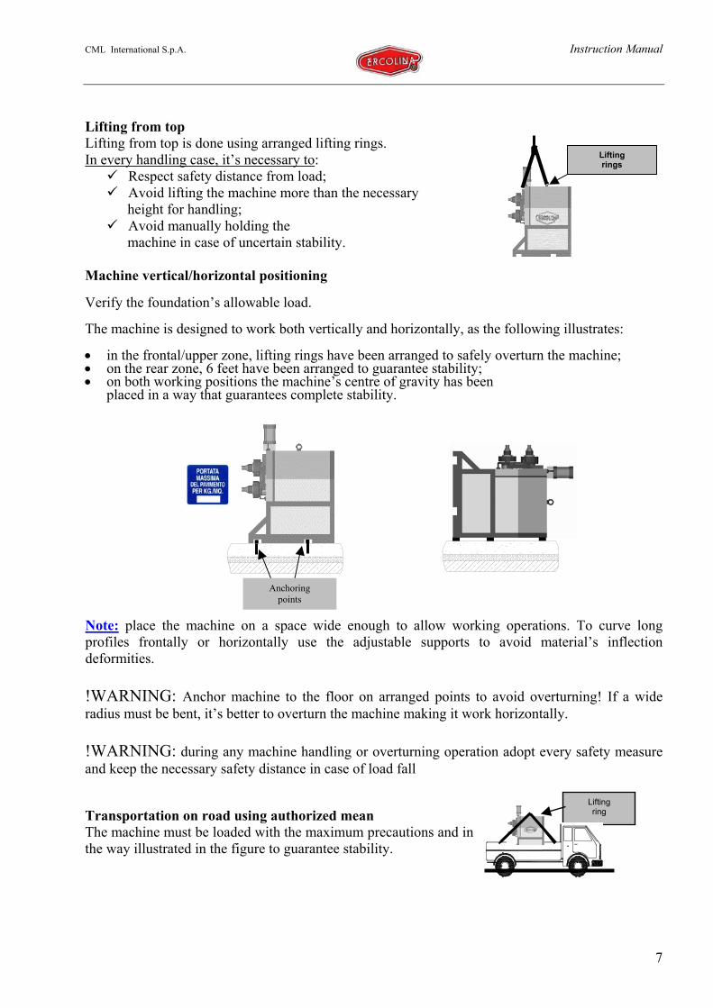
Liftingrings
Lifting from topLifting from top is done using arranged lifting rings.In every handling case, it’s necessary to:
Respect safety distance from load; Avoid lifting the machine more than the necessary
height for handling; Avoid manually holding the
machine in case of uncertain stability.
Machine vertical/horizontal positioning
Verify the foundation’s allowable load.
The machine is designed to work both vertically and horizontally, as the following illustrates:
• in the frontal/upper zone, lifting rings have been arranged to safely overturn the machine;• on the rear zone, 6 feet have been arranged to guarantee stability;• on both working positions the machine’s centre of gravity has been
placed in a way that guarantees complete stability.
Note: place the machine on a space wide enough to allow working operations. To curve longprofiles frontally or horizontally use the adjustable supports to avoid material’s inflectiondeformities.
!WARNING: Anchor machine to the floor on arranged points to avoid overturning! If a wideradius must be bent, it’s better to overturn the machine making it work horizontally.
!WARNING: during any machine handling or overturning operation adopt every safety measureand keep the necessary safety distance in case of load fall
Transportation on road using authorized meanThe machine must be loaded with the maximum precautions and inthe way illustrated in the figure to guarantee stability.
Liftingring
Anchoringpoints
CML International S.p.A. Instruction Manual
8
SAFETY NORMSOverviewActive safetyAccording to the machine technical and operating characteristics and to the variety of products towork, applying fixed or removable protections on bending rolls would obstruct the use of thismachine.
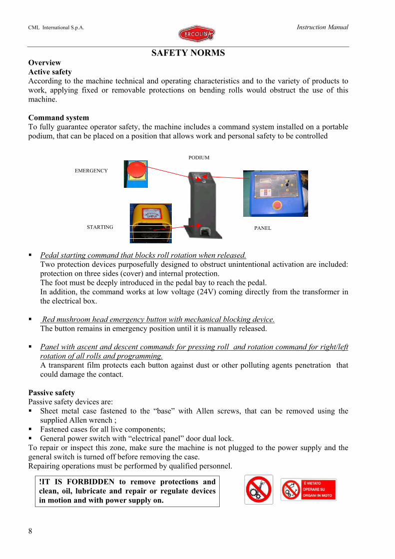
Command systemTo fully guarantee operator safety, the machine includes a command system installed on a portablepodium, that can be placed on a position that allows work and personal safety to be controlled
Pedal starting command that blocks roll rotation when released.Two protection devices purposefully designed to obstruct unintentional activation are included:protection on three sides (cover) and internal protection.The foot must be deeply introduced in the pedal bay to reach the pedal.In addition, the command works at low voltage (24V) coming directly from the transformer inthe electrical box.
Red mushroom head emergency button with mechanical blocking device.The button remains in emergency position until it is manually released.
Panel with ascent and descent commands for pressing roll and rotation command for right/leftrotation of all rolls and programming.A transparent film protects each button against dust or other polluting agents penetration thatcould damage the contact.
Passive safetyPassive safety devices are: Sheet metal case fastened to the “base” with Allen screws, that can be removed using the
supplied Allen wrench ; Fastened cases for all live components; General power switch with “electrical panel” door dual lock.
To repair or inspect this zone, make sure the machine is not plugged to the power supply and thegeneral switch is turned off before removing the case.Repairing operations must be performed by qualified personnel.
PANELSTARTING
EMERGENCY
PODIUM
!IT IS FORBIDDEN to remove protections andclean, oil, lubricate and repair or regulate devicesin motion and with power supply on.
CML International S.p.A. Instruction Manual
9
Prescriptions
Connect and use the machine without carefully consulting the Use and Maintenance
Manual;
Remove motor protections;
Assemble or remove equipment with the general switch on or with the rolls in motion;
Operate on the electrical system without switching off power supply;
Move the machine using inadequate lifting equipment;
Try to manually hold an unsteady load;
Modify the electrical system;
Modify the machine’s rolling speed or the work pressure;
Be distracted when bending or assembling equipment;
Lay hands on material while it moves forward;
Have more than one person working on the same machine;
Have a limited working area compared with the length of the profiles to be worked;
Use the machine beyond the indicated maximum capacity;
Use the machine for other than bending;
Perform maintenance or repairing by unqualified personnel;
Assemble rolls or equipment incompatible with those supplied by CML International
S.p.A.;
Clean machine parts without previously switching off power supply;
Use hands to lift the profile when bending more than 360°;
Stand over or under the profile entering or exiting the machine;
Operate rotation with hands laid on the profile entering between the rolls;
Leave the machine unattended with power on.
FORBIDDEN
CML International S.p.A. Instruction Manual
10
ADEQUATELY TRAIN PERSONNEL ASSIGNED TO MACHINE USE
! Use protective gloves to manage the material;
! Use protective helmet when profiles are suspended or directed upwards;
! Use protective shoes, useful in case of heavy loads fall;
! Use protective lens to defend eyes from filings that can be dropped from the profile
when bending;
! Keep the emergency button installed on the command podium within reach;
! The person who operates machine movements must also introduce and extract the
profile to be worked;
! Keep adequate space in front of the machine and in the operator’s working area;
! Pay attention to the part exiting the roll’s grooves;
! Carefully read plates and warning signals placed on the machine;
! Always stand to the side of the entering and exiting profile at a safety distance from the
machine;
! Confine the bending operation working area using barriers and/or chains.
!!WARNING: further protection devices can be made by the operatoror by the person responsible for machine use. Our project departmentis available to give opportune advice or to satisfy any request.
MANDATORY

CML International S.p.A. Instruction Manual
11
Machine equipment
The machine’s equipment is able to bend most commercial profiles and special accessories can beassembled to bend profiles of particular geometries and dimensions.
Standard equipment:
Standard rolls
Shoulder rolls with special rectifier to bend leg in/leg out profiles
Lifting rings for overturning/lifting
Use and Maintenance manual
Programming Manual
Safety Manual
Service wrenches
Optional accessories
To perform non standard bending, the machine can be equipped with the following accessories:
Bending rolls for special profiles and tubes;
Tie bar to increase shaft rigidity
Arch meter
Protection barriers
Service hoist

CML International S.p.A. Instruction Manual
12
BENDING CAPACITY
We recommend not to use themachine beyond the indicatedmaximum capacity to prevent
permanently deforming some machine devices.Legend:RS: Set of three standard rollsRT: Set of three rolls for solid profilesSR: Set of three special rollsTI: tie bar to increase shaft rigidityRA: Anti-twist device angle leg-in
Note: The machine was designed to bend the biggest profiles included in the tables, since they offer the highestresistance module. Minimal radius refer to material with a resistance of 45 Kg/mm² and obtained with one or more passes.Note.: for some profiles such as tubes or other pipes, prescribed minimal radius do not depend on themachine’s maximum capacity, but on the plastic deformation limit on which marked ovaling/protrusion isavoided.If marked ovaling/protrusion conditions are accepted, profiles can be bent with a minimal radius, considerablyunder values indicated on the table.
We recommend to not exceed the prescribed maximum capacities so as to not cause permanent deformations ofsome components of the machine.
Profile Dimensions(mm)/(“)
Radiusmin
(mm)/(“)
Rolls(type)
30X5/1,18X0,20
120X20/4,72X0,79
250/10
500/20RSRS
50 x 10 / 1,97 x 0,39
200 x 40 / 7,87 x 1,57
250 / 10
500 / 20RS
SR – TI
30 x 30 x 5 / 1,18 x 1,18 x 0,197
80 x 80 x 12 / 3,15 x 3,15 x 0,472
100 x 100 x12/3,94 x3,94 x 0,472
250 / 10
500 / 20
600 / 24
RSRSRS
30 x 30 x 5 / 1,18 x 1,18 x 0,197
80 x 80 x 12 / 3,15 x 3,15 x 0.472
100x100x12 / 3,94 x 3,94 x 0,472
250 / 10
500 / 20
800 / 31
RSRSRS
30 x 30 x 5/1,18 x 1,18 x 0,197
100x100x12 / 3,94 x 3,94 x 0,472
200 / 8
500 / 20RS
RS – TI
30 x 30 x 5/1,18 x 1,18 x 0,197
100x100x12 / 3,94 x 3,94 x 0,472
250 / 10
500 / 20RS
RS – TI
U 40 x 35 / 1,57 x 1,38
UPN 180X70 / 7,09X2,75
UPN260X90/10,24X3,54
250 /10
400 /16
600 / 24
SRSR – TISR – TI
U 40 x 35 / U 1,57 x 1,38
UPN180X70/7,09”X2,75”
UPN260X90/10,24X3,54
250 / 10
400 / 16
600 / 24
SRSR – TISR – TI
IPN-IPE 80 ( 3,15”)
IPN-IPE 180 (7,09”)
IPN-IPE 240 (9,45”)
500 / 20
500 / 20
600 / 24
SRSR – TISR – TI
HE 100 B / 3,94
HE 140 A / 5,51
1000 / 39
1200 / 47SR - TISR – TI
Profile Dimensions(mm)/(“)
Radiusmin
(mm)/(“)
Rolls(type)
4“ x 4,50 / 4” x 0,180
4” x 5,4 / 4”x 0,21
5” x Sch40 / 5” x 0,258
600 / 24
800 / 31
1000 / 39
RTRT
RT+TI
30 x 2 / 1,18 x 0,08
150 x 4 / 5,9 x 0,157
250 / 10
1000 / 39
RTRT
30 x 30 x 2/ 1,18 x 1,18x0,079
120x120x4/4,7 2x4,72x 0,157
250 / 10
1300 / 51SR
SR – TI
30 x 15 x2/1,18 x 0,59 x 0,079
120 x 60 x 5/4,72x 2,.36x0,197
300 / 12
1500 / 59SR
SR – TI
30 x 15 x 2 / 1,18x0,59x0,079
140 x 60 x 5/5,51 x2,36x0,197
300 / 12
1500 / 59SR
SR – TI
30 x 15 x 1,5/1,18x0,59x0,059
100 x 50 x 3/3,94 x1,97x0,118
300 / 12
1000 / 39SR
SR – TI
30 x 15 x 1,5/1,18x0,59x0,059
120 x 60 x 3 / 4,72x2,36x0,120
300 / 12
1500 / 59SR
SR – TI
12 / 0,47
70 / 2,75
200 / 8
300 / 12RTRT
12/ 0,47
60 / 2,36
300 / 12
300 / 12RSRS
12 / 0,47
50 / 1,97
200 / 8
400 / 16SRSR
CML International S.p.A. Instruction Manual
13
Bending suggestions
Overview
All materials can be bent with our machines, bending results depend on material’s quality.
Main parameters that may influence bending:
• Elastic characteristics of material;• Section’s heterogeneity;• Material temperature;• Profile distortion;• Inflection of extremely long bars.
Standard multipurpose rolls
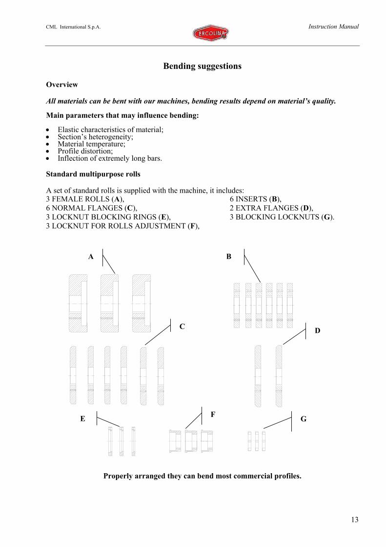
A set of standard rolls is supplied with the machine, it includes:3 FEMALE ROLLS (A), 6 INSERTS (B),6 NORMAL FLANGES (C), 2 EXTRA FLANGES (D),3 LOCKNUT BLOCKING RINGS (E), 3 BLOCKING LOCKNUTS (G).3 LOCKNUT FOR ROLLS ADJUSTMENT (F),
Properly arranged they can bend most commercial profiles.
A B
C D
E F G

CML International S.p.A. Instruction Manual
14
ROLLS ARRANGEMENT
Rolls must be correctly placed and well aligned according to the profile type to bend. This willavoid excessive machine strain and useless profile distortion.Rolls opening must be regulated to contain the profile and allow it to slide without excessivefriction.In most profiles, when bending, a remarkable swelling will be noticed in the centre ring, due tonatural compression: tightening rolls is advisable to avoid excessive deformation.
For a correct machine use and to avoid excessive strain and useless distortion, in the followingpages we include some assembling illustrations for different bending positions.
To solve profile bending problems under non standard conditions, please contact our projectdepartment.
“RECTANGULAR SOLID HARD WAY” BendingBeam dimensions that allow the illustrated assembly are normally workedwith rolls included in standard equipment.
Note: if filings are formed during working cycle, we suggest properadjustment of rolls tightness; furthermore it’s preferable to grease profilesurfaces to reduce friction.
“SQUARE SOLID” Bending
It’s worked with normal rolls included in standard equipment.If work is continuous , the machine should be equipped with rollshaving a groove as wide and deep as the material to bend.The upper roll housing groove must be regulated 0.5 mm wider thanthe material’s thickness
Note: if filings are formed during working cycle, we suggest properadjustment of rolls tightness; furthermore it’s preferable to greaseprofile surfaces to reduce friction.
A
BC
ABC
C
CML International S.p.A. Instruction Manual
15
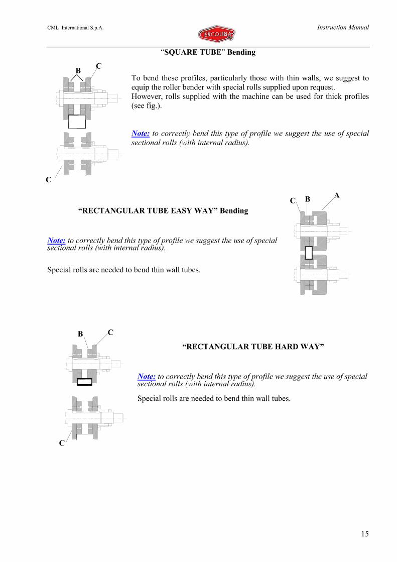
“SQUARE TUBE” Bending
To bend these profiles, particularly those with thin walls, we suggest toequip the roller bender with special rolls supplied upon request.However, rolls supplied with the machine can be used for thick profiles(see fig.).
Note: to correctly bend this type of profile we suggest the use of specialsectional rolls (with internal radius).
“RECTANGULAR TUBE EASY WAY” Bending
Note: to correctly bend this type of profile we suggest the use of specialsectional rolls (with internal radius).
Special rolls are needed to bend thin wall tubes.
“RECTANGULAR TUBE HARD WAY”
Note: to correctly bend this type of profile we suggest the use of specialsectional rolls (with internal radius).
Special rolls are needed to bend thin wall tubes.
C B A
B
C
C
CB
C

CML International S.p.A. Instruction Manual
16
“ANGLE LEG OUT”
Distortion is a great problem when bending these profiles: caused byunbalanced stresses due to the section’s geometric asymmetry.Consequently, the machine has been equipped with the necessary tools toeliminate this problem. (SEE FOLLOWING IMAGES)
Solution for distortion problem when bending profiles“ANGLE LEG OUT”:
Assemble equipment included in standard supply:
• Extra flanges that laterally support profiles;• Conical washer on shoulder roll.
Bending from left to right: Left rectifier must be aligned with material; to avoid distortion rightrectifier must be positioned in a way that allows conical washer to work.
D
BCA

CML International S.p.A. Instruction Manual
17
“ANGLE LEG IN” Bending
Distortion is a great problem when bending these profiles: caused byunbalanced stresses due to the section’s geometric asymmetry.Consequently, the machine has been equipped with the necessarytools to eliminate this problem.
Solution for distortion problem when bending profiles“ANGLE LEG IN”.
Assemble equipment included in standard supply:• Extra flanges that laterally support profiles;• Cylindrical washer on shoulder roll.Bending from left to right: Left rectifier must be aligned withmaterial; to avoid distortion right rectifier must be positioned in away that allows conical washer to work.
Operations needed to avoid distortion:
1. Move washer touching angle’s internal side;2. Lay roll on angle beam;
“T LEG OUT”/“T LEG IN”
If a rigorous orthogonality between the legbended hard way and the bending surface isrequired, assembling a tie bar at shaftextremities is necessary to increase theirrigidity and avoid shaft’s flexion as much aspossible. These tie bars can be supplied uponrequest.
Washer
Roll
AC
B
B
DA
C

CML International S.p.A. Instruction Manual
18
INTEGRATIVE NOTE OF CE100 USE AND MAINTENANCE INSTRUCTION MANUAL
“ ANGLE LEG IN “ RING ROLLING
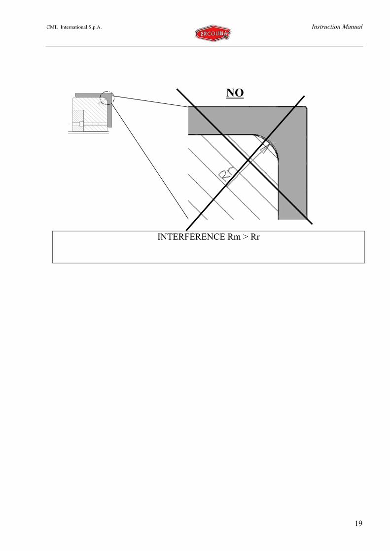
!!!!WARNING
SET CORRECTLY THE RING ROLLS
Before rolling the following represented profile, check that:
I. CASE: the radius of the roll ( Rr ) is not bigger than at least 1 ÷ 2 mm the
radius of the angle bar ( Rra ). In such case it is not possible to start rolling,
since the roll would tend to deform the profile surface.
II. CASE: the radius of the roll ( Rr ) is shorther than at least 1 ÷ 2 mm the
radius of the angle bar ( Rra ), in such case it is possible to start rolling,
since the roll will not penetrate the profile surface.
To understand better the above, make reference to the following pictures.
CML International S.p.A. Instruction Manual
19
INTERFERENCE Rm > Rr
NO

CML International S.p.A. Instruction Manual
20
YES
CML International S.p.A. Instruction Manual
21
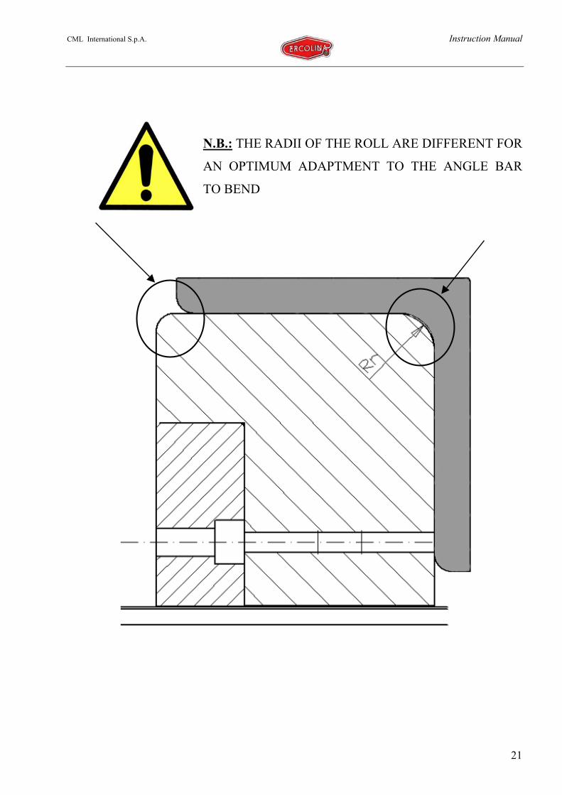
N.B.: THE RADII OF THE ROLL ARE DIFFERENT FOR
AN OPTIMUM ADAPTMENT TO THE ANGLE BAR
TO BEND

CML International S.p.A. Instruction Manual
22
“T LEG UP” Bending “C LEG OUT” Bending
“C LEG IN” Bending
For profiles of small dimensions rolls supplied with machine can be used.For biggest profiles we suggest to equip the roller bender with special rolls supplied uponrequest. Using tie bars is in any case advisable to avoid excessive inflection of shafts.
BAC
ABC
CB
C
CML International S.p.A. Instruction Manual
23
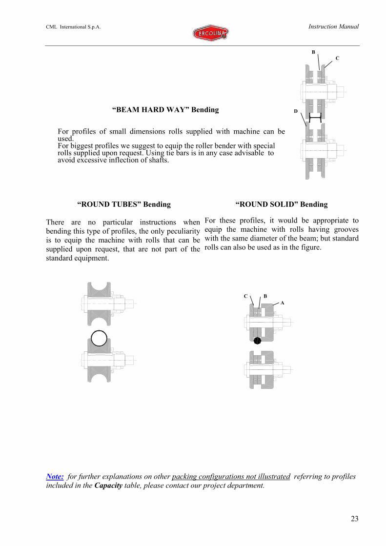
“BEAM HARD WAY” Bending
For profiles of small dimensions rolls supplied with machine can beused.For biggest profiles we suggest to equip the roller bender with specialrolls supplied upon request. Using tie bars is in any case advisable toavoid excessive inflection of shafts.
“ROUND TUBES” Bending
There are no particular instructions whenbending this type of profiles, the only peculiarityis to equip the machine with rolls that can besupplied upon request, that are not part of thestandard equipment.
“ROUND SOLID” Bending
For these profiles, it would be appropriate toequip the machine with rolls having grooveswith the same diameter of the beam; but standardrolls can also be used as in the figure.
Note: for further explanations on other packing configurations not illustrated referring to profilesincluded in the Capacity table, please contact our project department.
CB
D
ABC
CML International S.p.A. Instruction Manual
24
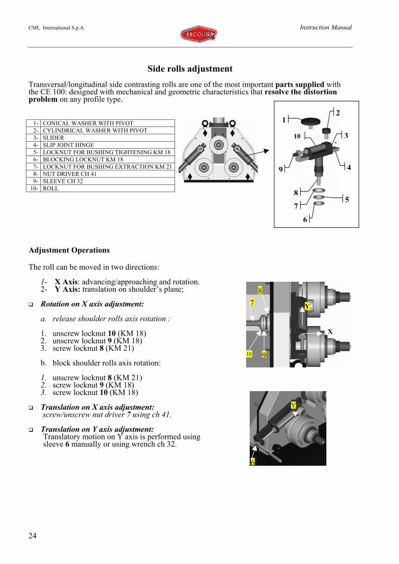
Side rolls adjustmentTransversal/longitudinal side contrasting rolls are one of the most important parts supplied withthe CE 100: designed with mechanical and geometric characteristics that resolve the distortionproblem on any profile type.
Adjustment Operations
The roll can be moved in two directions:
1- X Axis: advancing/approaching and rotation.2- Y Axis: translation on shoulder’s plane;
Rotation on X axis adjustment:
a. release shoulder rolls axis rotation :
1. unscrew locknut 10 (KM 18)2. unscrew locknut 9 (KM 18)3. screw locknut 8 (KM 21)
b. block shoulder rolls axis rotation:
1. unscrew locknut 8 (KM 21)2. screw locknut 9 (KM 18)3. screw locknut 10 (KM 18)
Translation on X axis adjustment: screw/unscrew nut driver 7 using ch 41.
Translation on Y axis adjustment:Translatory motion on Y axis is performed usingsleeve 6 manually or using wrench ch 32.
1- CONICAL WASHER WITH PIVOT2- CYLINDRICAL WASHER WITH PIVOT3- SLIDER4- SLIP JOINT HINGE5- LOCKNUT FOR BUSHING TIGHTENING KM 186- BLOCKING LOCKNUT KM 187- LOCKNUT FOR BUSHING EXTRACTION KM 218- NUT DRIVER CH 419- SLEEVE CH 32
10- ROLL
1
7
8
9
3
4
2
5
6
10
10 9
78
Y
X
6
Y
CML International S.p.A. Instruction Manual
25
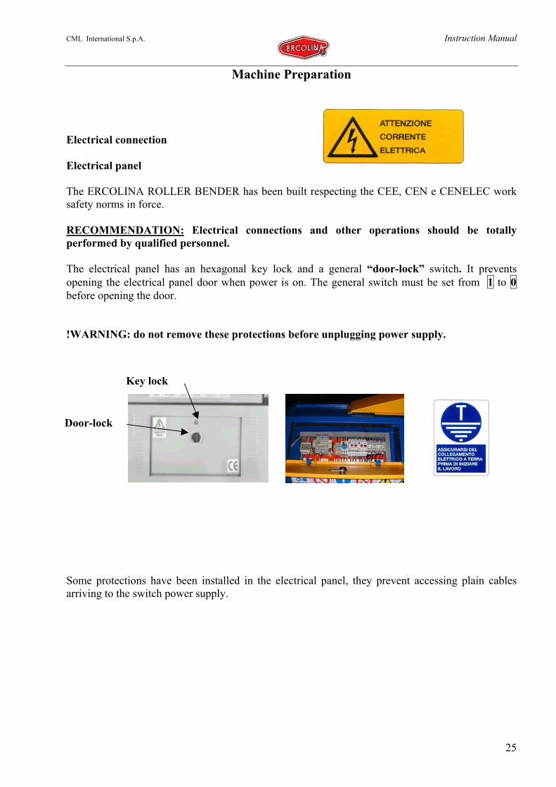
Machine Preparation
Electrical connection
Electrical panel
The ERCOLINA ROLLER BENDER has been built respecting the CEE, CEN e CENELEC worksafety norms in force.
RECOMMENDATION: Electrical connections and other operations should be totallyperformed by qualified personnel.
The electrical panel has an hexagonal key lock and a general “door-lock” switch. It preventsopening the electrical panel door when power is on. The general switch must be set from 1 to 0before opening the door.
!WARNING: do not remove these protections before unplugging power supply.
Some protections have been installed in the electrical panel, they prevent accessing plain cablesarriving to the switch power supply.
Door-lock
Key lock
CML International S.p.A. Instruction Manual
26
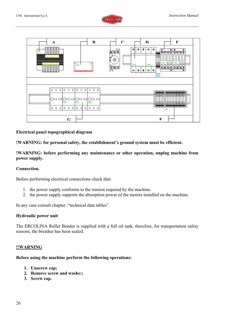
Electrical panel topographical diagram
!WARNING: for personal safety, the establishment’s ground system must be efficient.
!WARNING: before performing any maintenance or other operation, unplug machine frompower supply.
Connection.
Before performing electrical connections check that:
1. the power supply conforms to the tension required by the machine.2. the power supply supports the absorption power of the motors installed on the machine.
In any case consult chapter :“technical data tables”.
Hydraulic power unit
The ERCOLINA Roller Bender is supplied with a full oil tank, therefore, for transportation safetyreasons, the breather has been sealed.
!!WARNING
Before using the machine perform the following operations:
1. Unscrew cap;2. Remove screw and washer;3. Screw cap.
A B C D E
FG

CML International S.p.A. Instruction Manual
27
Troubleshooting
OverviewThis paragraph helps determining and possiblyresolving, some anomalies that may occur during thelife of the ERCOLINA ROLLER BENDER.
The table does not include damages or failures caused by misuse or by a use beyond the machine’scapacity, where it’s not possible to foresee which components could be exposed to strain or broken.The technical service centre can help you by phone, fax or email to identify the failure if enoughinformation is supplied:
1. Type of anomaly found;2. Detailed description of operations with anomaly found;3. Description of movements and diagnostic control lights during anomaly;4. Anomaly recurrence;5. Working environment conditions.
In any case, before calling we suggest to check if you can find a reference to the machine failure inthe following table.
Anomalies Diagnosis Solution
The machine turns on, but thepiston doesn’t work.
An input phase of the powerunit is inverted.
Remove plug and invertphase wires in the plug.
The control panel display remainsoff.
The pedal unit is not connectedto the power supply
Connect pedal unit topower supply using theplug located in themachine body.
Rolls don’t rotate when pedal ispressed.
Thermomagnetic protection isdisactivated.
Check that switches onpanel are turned on (I).
Pressing roll is not kept in position,it jumps when bending.
Air has been developed onhydraulic system.
Discharge system (consultMAINTENANCE section).
Pressing roll is not kept in position,it looses quota when bending.
An oil loss on hydraulic systemor on lock valve or on piston’sgaskets.
Substitute the lock valveor remove the piston andsubstitute gaskets.
The roll is not kept in position, itslowly looses quota when materialpasses between rolls.
An oil loss on hydraulic systemor on lock valve by thehydraulic piston or on piston’sgaskets.
Substitute the lock valveor remove the piston andsubstitute gaskets.
The upper roll sometimes doesn’tpull the profile enough.
Friction slides because offriction pads wearing.
Friction must be tightened(see friction adjustment).

CML International S.p.A. Instruction Manual
28
Anomaly Diagnosis Solution
Bending rolls rotation is toonoisy.
Power supply might notconform to machine needs orthe three phases are notpresent.
Check Power supply andmachine requirements (seeidentification plate) andcheck that the three phasesare included in the powersupply. Control fuses oneach phase.Adapt Power supply to fitmachine requirements orcall the nearest servicecentre.Restore the missing phaseor substitute fuse.
The machine is excessivelystrained and is too noisy.
Bushes might be blockedbecause of lack of oil.
Bushes must be substitutedby qualified personnel.Check that lubrication oilcomes out from nozzlesnear bushes and from theother parts to belubricated.
During centre roll’s ascent ordescent the panel does not showdisplaced millimetres.
Encoder not connected ordamaged.
Substitute encoder or verifyits integrity.
Machine turns on but the pistondoesn’t work. Emergency button pressed. Remove emergency.The piston seems not to have theright driving force. Lack of oil on hydraulic circuit. Add hydraulic oil on unit.

CML International S.p.A. Instruction Manual
29
Maintenance
The machine requires very little maintenance because of its solidity and technical design, but in anycase it must be performed regularly.
!WARNING: all maintenance activities must be safely performed by qualified personnel.
For a long working life it’s advisable to perform some periodical check ups at regular intervals.(Monthly maintenance)
LubricationDifferent machine devices must be lubricated: The shoulder correcting rolls, assembled in a particular steel support must be lubricated every
1.000 h.
BearingsThe machine includes bearings on rotating parts.Motion shafts have tapered roller bearings, that perform a double function:
Axial and radial play holding; Possibility to be regulated to eliminate play.
They do not need lubrication since they’re sealed and permanently lubricated.They can be occasionally regulated, if shaft play is excessive.
Bearings regulation:1. Remove inspection panel after unplugging power supply (including the one coming directly
from electrical panel);2. Locate driving shafts. Shafts are blocked by two locknuts the rear one is self-locking;3. Loosen the clamp screw using the spanner;4. Screw the blocking locknut (front): we suggest screwing the locknut until the shaft can be
manually rotated.5. Tighten the self-locking clamp screw;6. Close machine’s inspection panel.
RECOMMENDATION: qualified personnel should perform these adjustments since this work isimportant for machine’s operation and working life.
!WARNINGThese operations cannot be performed with machine turned off.Remove bending rolls before performing these operations to avoidcollision between rolls. Do not lay hands on shafts or devices inmotion to avoid crushing.

CML International S.p.A. Instruction Manual
30
Hydraulic power unit
The machine includes a hydraulic power unit that drives the piston.It is a closed circuit hydraulic system, this means that the same oil used to fill the piston’s chamberis automatically re-introduced in the tank when emptying.During the first working hours it is necessary to check the tank’s fluid level to control if there areleakage points.After the first 100 working hours check filters cleanliness and calibrations.Every 3000 working hours substitute liquid and filtering elements.
Checking oil level
At regular intervals (every month) it is necessary to check tank’s oil level.To perform this, make sure general switch is off and power supply is unplugged, then loosenfastening screws to remove panel. Unscrew the fill cap and visually check the oil level that must beslightly under the cap level. It’s better to perform this operation with the machine in verticalposition.
Refilling
The oil level in the power unit must be restored at least every 1000 working hours.Before refilling make sure general switch is off and power supply unplugged. Unscrew the powerunit’s tank cap and use a funnel to restore the oil level (see technical tables: suggested lubricants).Screw cap and restore power supply to the machine.
Discharges
When the power unit is not able to take in oil because of low oil level or for other hydraulic systemreasons, air bubbles that cause several machine anomalies are formed; in these cases the roll doesn’tkeep its position and “jumps” when profile is inserted and when bending: the air cushion formed,since it can be compressed, allows piston oscillation. To perform the air discharge, the hydraulicpiston has two screws.
CML International S.p.A. Instruction Manual
31
Changing oil
Every 10.000 working hours the hydraulic oil in the power unit must be substituted.The following procedure explains how to perform the operation:
1. Completely pull down the hydraulic piston;2. Make sure general switch is off;3. Remove the lower-right panel: loosening screws;4. Remove solenoid valve and motor from electrical connections;5. Remove hydraulic tubes connected to the piston;6. Loosen fastening screws on base power unit;7. Extract power unit from base;8. Unscrew drain cap and completely empty the tank;9. Screw drain cap adding teflon on the thread to avoid loss, pay attention not to introduce filings
in the power unit. Fill the tank with appropriate hydraulic oil, using adequate filtering means tokeep impurities and dirt from getting into the power unit, since they could provoke a machinefunction failure;
10. Re-assemble everything reversing the previously described operations.
!!WARNING: when performing those operations, be extremely careful not to introduceimpurities that could seriously damage the machine’s hydraulic components.
For grease and oil type consult technical tables
!!WARNING: depleted oil must not be dispersed in the environment, it should be disposedfollowing the norms in force.
CML International S.p.A. Instruction Manual
32
Gear motors
After a 200 hours working period, perform a gear system oil change and wash the inside with liquiddetergent.
Oil change operations: verify diagrams and specifications in the attached gear system manual.
The following oil changes must be performed every 2000 working hours.For the oil type consult the lubricant table.
Cleaning
Overview
When bending ferrous materials, abundant filings dropped from the material’s surface cover themachine.If these filings get into the machine’s sliding guides they could block it causing semi-irreparabledamage, since the repairing cost is very high.The machine becomes more vulnerable if it works in a horizontal position (at vertical axes).For this reason the machine is equipped with a sliding door designed to keep scraps out of themachine avoiding damages to its components.
Machine cleaning
We suggest you regularly clean the machine from filings, according to the quantity of filingsdropped on the machine, particularly if work requires a continuous bending roll adjustment.To perform this cleaning avoid blowing compressed air, since filings could be blown into themachine causing the difficulties indicated above.
Use a brush to eliminate the bigger filings, trying to throw them away from the machine and awayfrom the mobile mechanic parts.Once surface filings are completely eliminated, compressed air can be used to eliminate dust tracesin the guides.
Note:
In the event of a temporary disuse, (less than two months) it’s not necessary to follow particularprecautions.
In the event of a prolonged disuse, (more than two months), we suggest turning the machine onfor some minutes at regular intervals, approximately every two months, without pressure toguarantee internal lubrication of components.
Precautions: when performing these operations the flooraround the machine should also be cleaned to remove oiltraces and avoid slippery surfaces.Use non slip shoes.
CML International S.p.A. Instruction Manual
33
Risk prevention solutions
Machine stop operations
By the operator (voluntarily and involuntarily): pressing the emergency button at any point andwith any angle. It is so sensitive that a minimal impulse is enough to interrupt roll motion;
By a third person: operating directly on the general switch or the emergency button.
If an improbable permanent blocking and /or crushing accident occurs, it’s necessary to carefullyevaluate the most suitable operation to perform:
1. Invert the advancing direction of the upper roll;2. Rotate rolls to facilitate extraction;3. Loosen the tightening locknut
!WARNING: in both conditions the reaction of material inserted between rolls should beevaluated. Before performing the operation, foresee the logical reaction movement of thematerial and behave consequently.
Risks due to fall or projection of bent part
While the machine works there is no risk of working parts, filings, shavings or fragmentsprojection.
dangerous situations that may arise are:
1. The part, once bending is completed, might fall from the rolls. This situation can bedangerous if the part was bent at a wide radius, since the falling part could harm theoperator.
2. The part can remain caught between the rolls in motion, and be dragged in the rotation notheld by the three rolls;
3. When bending, the material could remain blocked between the roll grooves and stop theirrotation: carefully evaluate the tightening locknut regulation; it’s a good rule to leave asmall play to admit swelling.
!!MANDATORY: USE PROTECTIVE SHOES (D. p. i.)
CML International S.p.A. Instruction Manual
34
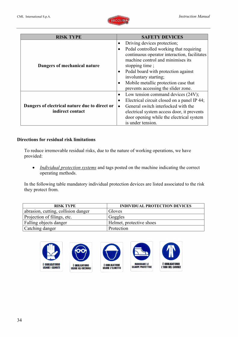
RISK TYPE SAFETY DEVICES
Dangers of mechanical nature
• Driving devices protection;• Pedal controlled working that requiring
continuous operator interaction, facilitatesmachine control and minimises itsstopping time ;
• Pedal board with protection againstinvoluntary starting;
• Mobile metallic protection case thatprevents accessing the slider zone.
Dangers of electrical nature due to direct orindirect contact
• Low tension command devices (24V);• Electrical circuit closed on a panel IP 44;• General switch interlocked with the
electrical system access door, it preventsdoor opening while the electrical systemis under tension.
Directions for residual risk limitations
To reduce irremovable residual risks, due to the nature of working operations, we haveprovided:
• Individual protection systems and tags posted on the machine indicating the correctoperating methods.
In the following table mandatory individual protection devices are listed associated to the riskthey protect from.
RISK TYPE INDIVIDUAL PROTECTION DEVICESabrasion, cutting, collision danger GlovesProjection of filings, etc. GogglesFalling objects danger Helmet, protective shoesCatching danger Protection
CML International S.p.A. Instruction Manual
35
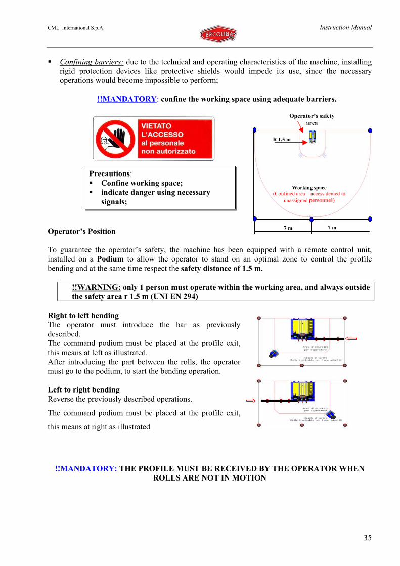
Precautions: Confine working space; indicate danger using necessary
signals;
Confining barriers: due to the technical and operating characteristics of the machine, installingrigid protection devices like protective shields would impede its use, since the necessaryoperations would become impossible to perform;
!!MANDATORY: confine the working space using adequate barriers.
Operator’s Position
To guarantee the operator’s safety, the machine has been equipped with a remote control unit,installed on a Podium to allow the operator to stand on an optimal zone to control the profilebending and at the same time respect the safety distance of 1.5 m.
!!WARNING: only 1 person must operate within the working area, and always outsidethe safety area r 1.5 m (UNI EN 294)
Right to left bendingThe operator must introduce the bar as previouslydescribed.The command podium must be placed at the profile exit,this means at left as illustrated.After introducing the part between the rolls, the operatormust go to the podium, to start the bending operation.
Left to right bendingReverse the previously described operations.
The command podium must be placed at the profile exit,
this means at right as illustrated
!!MANDATORY: THE PROFILE MUST BE RECEIVED BY THE OPERATOR WHENROLLS ARE NOT IN MOTION
7 m 7 m
Working space(Confined area – access denied to
unassigned personnel)
Operator’s safetyarea
R 1,5 m
CML International S.p.A. Instruction Manual
36
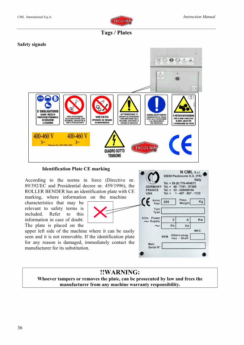
Tags / Plates
Safety signals
Identification Plate CE marking
According to the norms in force (Directive nr.89/392/EC and Presidential decree nr. 459/1996), theROLLER BENDER has an identification plate with CEmarking, where information on the machinecharacteristics that may berelevant to safety terms isincluded. Refer to thisinformation in case of doubt.The plate is placed on theupper left side of the machine where it can be easilyseen and it is not removable. If the identification platefor any reason is damaged, immediately contact themanufacturer for its substitution.
!!WARNING:Whoever tampers or removes the plate, can be prosecuted by law and frees the
manufacturer from any machine warranty responsibility.
CML International S.p.A. Instruction Manual
37
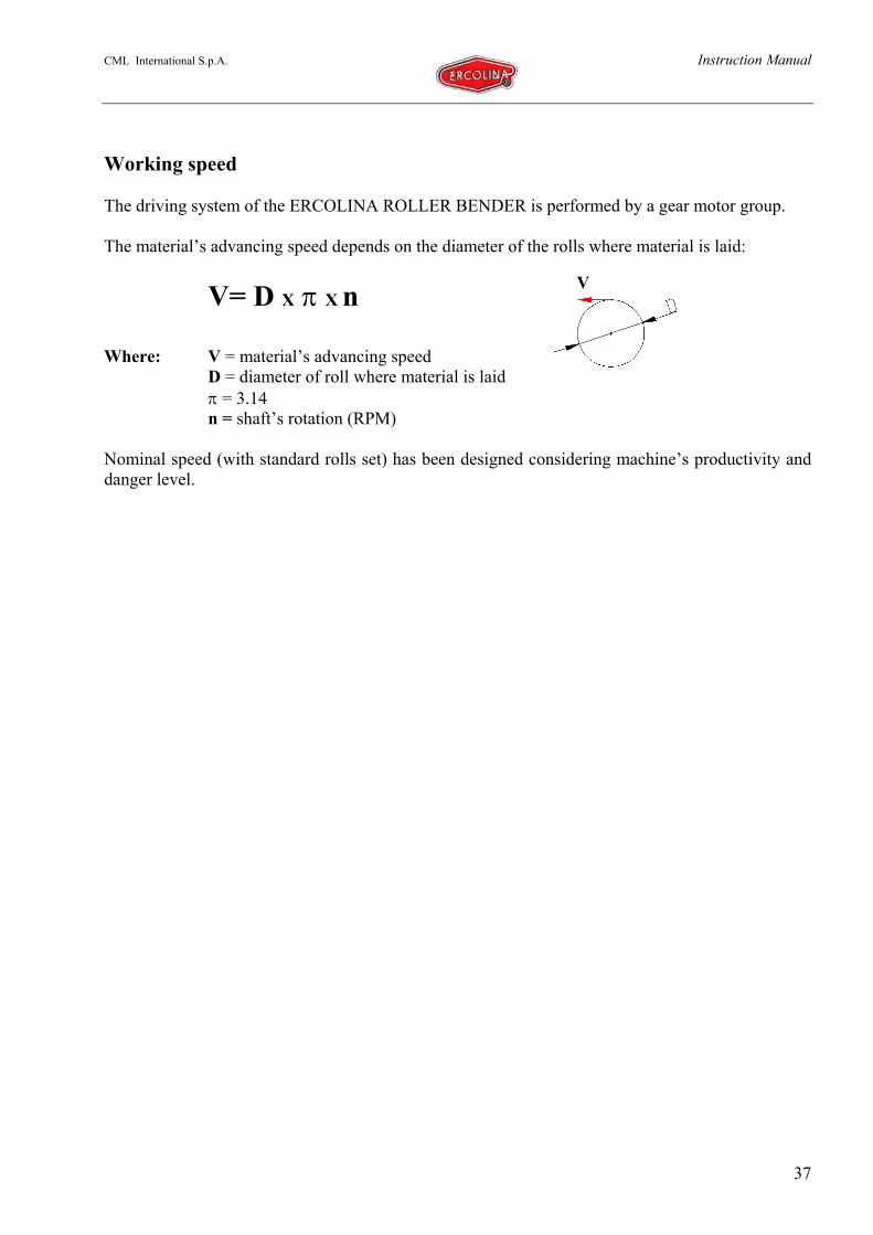
Working speed
The driving system of the ERCOLINA ROLLER BENDER is performed by a gear motor group.
The material’s advancing speed depends on the diameter of the rolls where material is laid:
V= D X π X n
Where: V = material’s advancing speedD = diameter of roll where material is laidπ = 3.14n = shaft’s rotation (RPM)
Nominal speed (with standard rolls set) has been designed considering machine’s productivity anddanger level.
V

CML International S.p.A. Instruction Manual
38
Scraps disposal
Machine demolition
We recommend deactivating the machine, before proceeding to its demolition:
Disassembling its components; Removing the motor
Before performing these operations completely empty hydraulic system and gear system from oils.
Ecological information
The disposal of the ROLLER BENDER packing materials, substituted parts, lubricants,components or of the machine itself, must be performed respecting the environment, avoidingground, water and air pollution.It’s the duty of the machine owner to perform this operation conforming to norms in force in thecountry where the machine is used.
Indications for correct waste disposal
Ferrous materials, aluminium, copper: are recyclable materials that must be taken to theproper authorized collecting centre;
Plastic and rubber materials: must be taken to a refuse disposal site or to the properrecycling centre;
Depleted oils: deliver to the proper authorized collecting centre (in Italy: ConsorzioObbligatorio Olii Esausti).

CML International S.p.A. Instruction Manual
39
Technical tables
Technical data tables
Technical characteristics Measure unit Mod. CE 100
SHAFT DIAMETERS (On Rollsand Bearings) mm 100
Standard Rolls Diameter mm 310Shafts speed RPM 6Standard Shafts working length Mm 200Upper Roll motor( 230 V,Y 400 V) KW 1,8Lower Roll Motor( 230 V,Y 400 V) KW 2 x 1,5Hydraulic Power UnitMotor(.∆..230 V,Y 400 V) KW 2.2
Piston thrust Ton 36Thrust Roll Max. Stroke Mm 200Nr. Of Driving Rolls 3/smoothMachine’s Working Surface horiz.-vert.Centre Roll Regulation HydCentre Roll Reading Digital progr.Base YESTridimentional Contrasting SideRolls YES
Bt Electrical Foot Pedal YESSteel Machine Body C 40Noise Rating dB <70
Dimensions TableDescription Measure Unit Mod. CE 100
Overall Dimensions (base xlength x height) Cm 145 x 190 x 150
Packed dimensions cm. 150 x 200 x 160
Weights TableDescription Measure Unit Mod.CE 100
Net machine weight Kg 2100
Machine weight with standardequipment Kg 2200
Packing weight Kg 15

CML International S.p.A. Instruction Manual
40
Environmental Table
List of lifting equipment
Suggested greases
Suggested Lubricants
Brand DIN 51524 Specifications DIN 51524 Specifications
HLP 32 HLP 46AGIP OSO 32 OSO 46BP ENERGOL HLP 32 ENERGOL HLP 46CASTROL HYSPIN AWS 32 HYSPIN AWS 46ELF ELFOLNA 32 ELFOLNA 46ESSO NUTO H 32 NUTO H 32FINA HYDRAN 32 HYDRAN 46IP HYDRUS 32 HYDRUS 46MOBIL DTE 24 DTE 25Q8 HAYDIN 32 HAYDIN 46SHELL TELLUS 32 TELLUS 46TEXANO RANDO HD 32 RANDO HD 46TOTAL AZOLLA ZS 32 AZOLLA ZS 46
Description Measure Unit Mod. CE 100Working Temperature °C 0-40Relative humidity 90%maxEnvironment Non explosive
Description Measure Unit CapacityTRANSPORT PALLET(with EC certification) Kg 3000
Description Brand EquivalentLubricant grease AGIP GR MU EP/0 SHELL ALVANIA
Sliding Grease AMECO, OPTIMOL VISCOGEN 4TYPE
Bearings Grease AGIP GRMUEP 2
CML International S.p.A. Instruction Manual
41
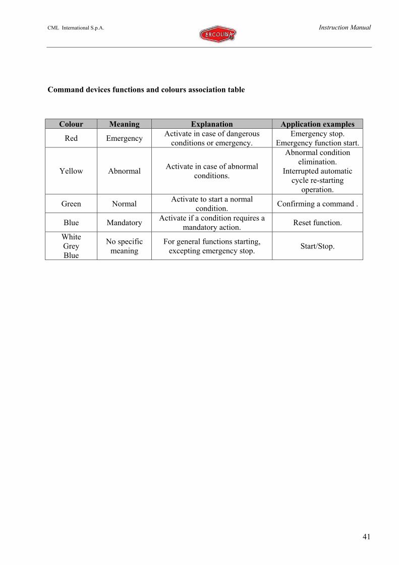
Command devices functions and colours association table
Colour Meaning Explanation Application examples
Red Emergency Activate in case of dangerousconditions or emergency.
Emergency stop.Emergency function start.
Yellow Abnormal Activate in case of abnormalconditions.
Abnormal conditionelimination.
Interrupted automaticcycle re-starting
operation.
Green Normal Activate to start a normalcondition. Confirming a command .
Blue Mandatory Activate if a condition requires amandatory action. Reset function.
WhiteGreyBlue
No specificmeaning
For general functions starting,excepting emergency stop. Start/Stop.

CML International S.p.A. Instruction Manual
42
Millimetres to inches conversion table
Inches 0" 1" 2" 3" 4" 5"mm Mm mm mm mm mm
0" — 25,400. 50,8 76.200 101,8 127.0001/64" 0,397 25,797 51,197 76.597 101.997 127.3971/32" 0,794 26,194 51,594 76,994 102.394 127,7943/64" 1,191 26,591 51,991 77.391 102,791 128.1911/16" 1,588 26,988 52.388 77,788 103,188 128,5885/64" 1.984 27,384 52,784 78,184 103584 128,9843/32" 2,381 27,781 53,181 78.581 103,981 129,3817/64" 2.778 28,178 53,578 78.978 104,378 129,7781/8" 3,175 28,575 53,975 79,375 104,775 130.175
9/64" 3.572 28.972 54.372 79.772 105.172 130.5725/32" 3.969 29.369 54,769 80,169 105,569 130.96911/64" 4,366 29,766 55,166 80,566 105,966 131,3663/16" 4,762 30,162 55,562 80,962 106,362 131,76213/64" 5,159 30,559 55,959 81.359 106.759 132.1597/32" 5.556 30,956 56,356 81,756 107,156 132,55615/64" 5,953 31,353 56,753 82.153 107.553 132,953
1/4" 6.350 31 .750 57,15 82.550 107.950 133.35017/64" 6,747 32,147 57,547 82,947 108,347 133,7479/32" 7,144 32544 57,944 83,344 108,744 134,14419/64" 7,541 32,941 58,341 83,741 109.141 134,5415/16" 7,938 33,338 58,738 84,138 109,538 134,93821/64" 8.334 33,734 59,134 84,534 109.934 135,33411/32" 8,731 34.131 59,531 84,931 110,331 135,73123/64" 9,129 34.528 59,928 85.328 110,728 136,128
3/8" 9,525 34,925 60,325 85.725 111,125 136,52525/64" 9,922 35,322 60.722 86,122 111,522 136,92213/32" 10,319 35,719 61,119 86,519 111,919 137,31927/64" 10,716 36,116 61,516 86,916 112,316 137,7167/16" 11,112 36,512 61.912 87.312 112,712 138,11229/64" 11,509 36,909 62,309 87,709 113,109 138,50915/32" 11,906 37,306 62,706 88.106 113.506 138,90631/64" 12,303 37.703 63.103 38,503 113.903. 139.303
1/2" 12,7 38,1 63,5 88.900 114,3 139,733/64" 13,097 38,497 63,897 89.297 114,697 140,09717/32" 13,494 38,894 64,294 89.694 115,094 140,49435/64" 13,891 39,291 64,691 90,091 115,491 140,8919/16" 14.288 39,688 65,088 90,488 115,888 141,28837/64" 14.684 40,084 65,484 90,884 116.284 141,68419/32" 15,081 40,481 65,881 91,281 116,681 142,08139/64" 15.478 40,878 66,278 91.678 117,078 142,478
5/8" 15,875 41,275 66,675 92,075 117,475 142,87541/64" 16,272 41,672 67,072 92,472 117,872 143,27221/32" 16,669 42.069 67,469 92.869 118,269 143,66943/64" 17,066 42.466 67,866 93.266 118,666 144,06611/16" 17.462 42,862 68,262 93,662 119,062 144,46245/64" 17,859 43,259 68,659 94,059 119,459 144,85923/32" 18,256 43,656 69,056 94,456 119,856 145,25647/64" 18,653 44,053 69,453 94,853 120,253 145,653
3/4" 19,05 44,45 69,85 95.250 120,65 146,0549/64" 19,447 44,847 70,247 95,647 121,047 146,44725/32" 19,844 45,244 70,644 96,044 121,444 146,84451/64" 20,241 45,641 71,041 96,441 121,841 147,24113/16" 20,638 46,038 71,438 96,838 122,238 147,63853/64" 21,034 46,434 71,834 97,234 122,634 148,03427/32" 21,431 46,831 72,231 97,631 123,031 148,43155/64" 21,828 47,228 72.628 98,028 123,428 148,828
7/8" 22,225 47,625 73.025 98.425 123,825 149,22557/64" 22,622 48,022 73,422 98,822 124,222 149,62229/32" 23,019 48,419 73,819 99.219 124,619 150,01959/64" 23,416 48,816 74,216 99,616 125,016 150,41615/16" 23,812 49,212 74,612 100,012 125,412 150,81261/64" 24,209 49,609 75.009 100,409 125,809 151,20931/32" 24.606 50,006 75,406 100.806 126,206 151,60663/64" 25,003 50,403 75,803 101,203 126,603 152,003
CML International S.p.A. Instruction Manual
43
CORRECTING ROLL GROUP
R1 Locknut type KM18 SKFR2 SpacerR3 Locknut type KM21 SKFR4 Pressure bushing type AHX 319 SKFR5 Seeger Ring UNI 7435 - 50R6 Shim ringR7 QuillR8 Nut DriverR9 Tang A 10x8x40 UNI 6604-69R10 Sleeve for wrenchR11 Snap ring 8x32 UNI 6873-71R12 BushingR13 Shim washerR14 Slip-joint hingeR15 Millimetric ruler 250 mm lengthR16 Slider screwR17 Roll axisR18 SliderR19 Shim washerR20 BushingR21 RollR22 Roll blocking pivotR23 Screw UNI 5923 M10x20R24 Washer pivotR25 Bearing type 61909 SKFR26 WasherR27 SpacerR28 WasherR29 Screw UNI 5933 M6x20 8.8R30 Seeger Ring UNI 7437 - 68R31 Conical washer pivot spacerR32 Tapered roller bearings internal spacerR33 Tapered roller bearings external spacerR34 Conical washer pivotR35 Conical washer

CML International S.p.A. Instruction Manual
44
SHOULDER GROUP
S1 Screw UNI 5931 M12x40 - 8.8S2 Shoulder roll hubS3 Screw UNI 5931 M8x25 - 8.8S4 Rear tracksS5 Lifting rings M30 UNI 2947S6 ShoulderS7 Screw UNI 5931 M14x130 - 8.8S8 Screw UNI 5931 M14x150 - 8.8S9 Nut UNI 5588 M14 4DS10 Nipple A6 M8x1,25 - 5.8S11 Front tracksS12 Optical encoderS13 Washer UNI 1751 B6

CML International S.p.A. Instruction Manual
45
AXIS GROUP
A1 Locknut type KM16 SKFA2 WasherA3 Bearing type 32017x SKFA4 ShaftA5 Tang A 22x14x160 UNI 6604-69A6 Oil seal type A DIN 3760 CORCOSA7 Oil seal holding capA8 Screw UNI 5931 M6x30 - 8.8A9 Normal flange 305 mm diameter
A10 Bending roll 305 mm diameterA11 InsertA12 Screw UNI 5931 M8x40 - 8.8A13 Rolls regulation locknutA14 Rolls regulation locknut supportA15 Locking clamp screwA16 Shaft’s extremity protection hoodA17 Screw UNI 5931 M14x30 - 8.8A18 Larger flange 325 mm diameter

CML International S.p.A. Instruction Manual
46
SLIDER GROUP
C1 SliderC2 Screw UNI 5931 M18x110 - 12.9C3 Washer UNI 1751 B18C4 Hydraulic piston 160-70-200 AERREC5 Slider front plate
C6 Nipple for under pressure greasing 10 mmdiameter
C7 Screw UNI 5931 M16x70 - 12.9C8 Cylinder fastening pinC9 Cylinder fastening pin holding plateC10 Screw UNI 5931 M6x20 - 8.8C11 Bracket for encoder rackC12 Encoder rackC13 Rivets UNI 9200 A 4x8 Al/FeC14 Screw UNI 5931 M6x10 - 8.8
CML International S.p.A. Instruction Manual
47
MOTOR-GEAR SYSTEM GROUP
LOWER axis configuration UPPER axis configuration
MR1 Electrical motor 1,5 Kw 4 pole GAMARMR2 Electrical motor 2 Kw 4 pole GAMAR
MR3 Epicyclic gear system ET3020/FET/00BREVINI
MR4 Washer UNI 1751 B12

CML International S.p.A. Instruction Manual
48
SUPPORTING FRAME
A Supporting structureB Upper casingC Upper right casingD Lower right casingE Upper left casingF Lower left casing
B
E
A
C
D
F

CML International S.p.A. Instruction Manual
49
Hydraulic system scheme

CML International S.p.A. Instruction Manual
50
Electrical wiring diagramsDRAWING Nr.1

CML International S.p.A. Instruction Manual
51
DRAWING Nr.2
CML International S.p.A. Instruction Manual
52
DRAWING Nr. 3

CML International S.p.A. Instruction Manual
53
DRAWING Nr. 4
CML International S.p.A. Instruction Manual
54
DRAWING Nr. 5
CML International S.p.A. Instruction Manual
55
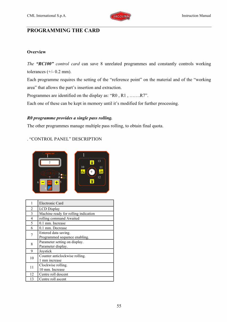
PROGRAMMING THE CARD
Overview
The “RC100” control card can save 8 unrelated programmes and constantly controls working
tolerances (+/- 0.2 mm).
Each programme requires the setting of the “reference point” on the material and of the “working
area” that allows the part’s insertion and extraction.
Programmes are identified on the display as: “R0 , R1 , …….R7”.
Each one of these can be kept in memory until it’s modified for further processing.
R0 programme provides a single pass rolling.
The other programmes manage multiple pass rolling, to obtain final quota.
. “CONTROL PANEL” DESCRIPTION
1 Electronic Card2 LCD Display3 Machine ready for rolling indication4 rolling command Awaited5 0.1 mm. Increase6 0.1 mm. Decrease
7 Entered data saving.Programmed sequence enabling.
8 Parameter setting on display.Parameter display.
9 Joystick
10 Counter anticlockwise rolling.1 mm increase
11 Clockwise rolling.10 mm. Increase
12 Centre roll descent13 Centre roll ascent
3
2
456
7
8
910 11
12
131 1
CML International S.p.A. Instruction Manual
56
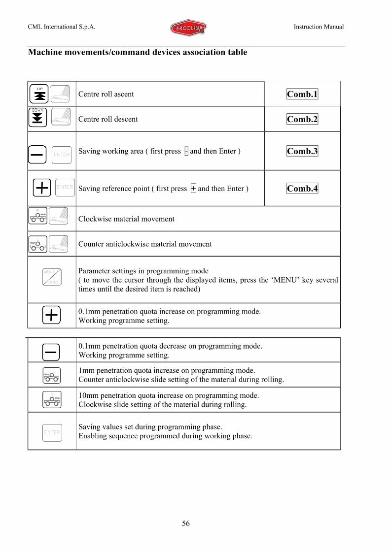
Machine movements/command devices association table
0.1mm penetration quota decrease on programming mode.Working programme setting.
1mm penetration quota increase on programming mode.Counter anticlockwise slide setting of the material during rolling.
10mm penetration quota increase on programming mode.Clockwise slide setting of the material during rolling.
Saving values set during programming phase.Enabling sequence programmed during working phase.
Centre roll ascent Comb.1
Centre roll descent Comb.2
Saving working area ( first press - and then Enter ) Comb.3
Saving reference point ( first press + and then Enter ) Comb.4
Clockwise material movement
Counter anticlockwise material movement
Parameter settings in programming mode( to move the cursor through the displayed items, press the ‘MENU’ key severaltimes until the desired item is reached)
0.1mm penetration quota increase on programming mode.Working programme setting.

CML International S.p.A. Instruction Manual
57
USER INTEFACE DISPLAY OF THE SOFTWARE PROGRAMMING SYSTEM
FUNCTIONAL MANAGEMENT OF STOPPING COMMANDS
1 Programme set (R0…R7)
2 Maximum increase quota (compared toreference point)
3 Centre roll sliding direction4 Material movement direction
5 Programmed increase per pass (not validfor R0 programme) 2 3 4 51
commandCENTRE ROLL
ASCENT
comandPEDAL
CENTRE ROLLASCENT&
commandCONTRAST ROLLS
CLOCKWISEROTATION
commandPEDAL
CONTRAST ROLLSCLOCKWISEROTATION&
commandCONTRAST ROLLS
COUNTER-CLOCKWISEROTATION
commandPEDAL
CONTRAST ROLLSCOUNTER-
CLOCKWISEROTATION
&
commandCENTRE ROLL
DESCENT
commandPEDAL
CENTRE ROLLDESCENT&
CML International S.p.A. Instruction Manual
58
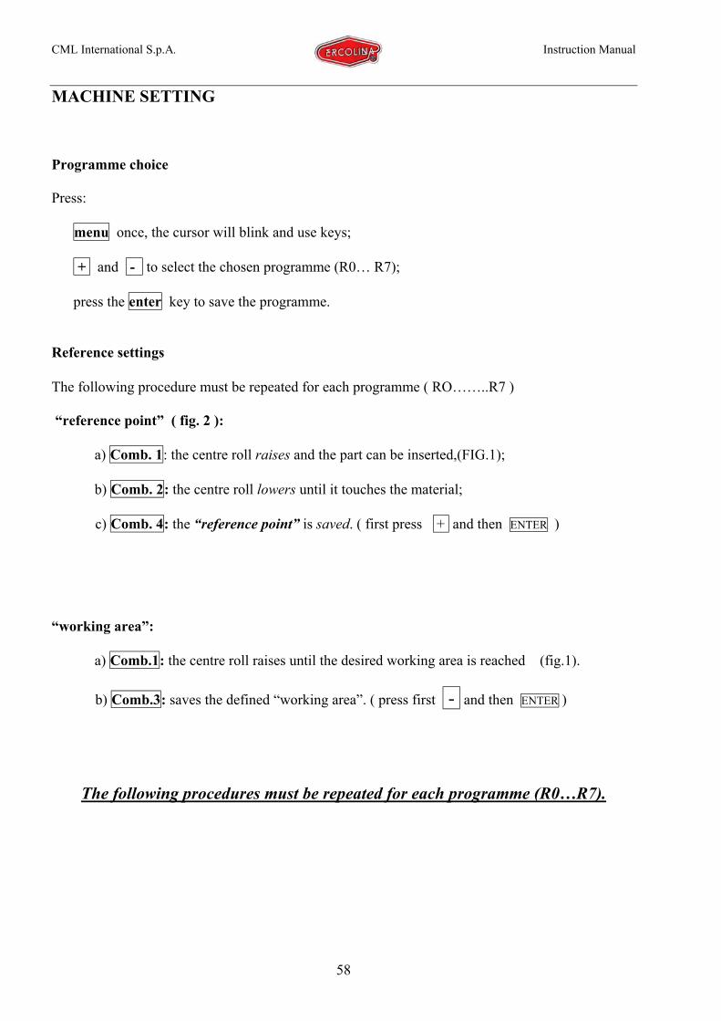
MACHINE SETTING
Programme choice
Press:
menu once, the cursor will blink and use keys;
+ and - to select the chosen programme (R0… R7);
press the enter key to save the programme.
Reference settings
The following procedure must be repeated for each programme ( RO……..R7 )
“reference point” ( fig. 2 ):
a) Comb. 1: the centre roll raises and the part can be inserted,(FIG.1);
b) Comb. 2: the centre roll lowers until it touches the material;
c) Comb. 4: the “reference point” is saved. ( first press + and then ENTER )
“working area”:
a) Comb.1: the centre roll raises until the desired working area is reached (fig.1).
b) Comb.3: saves the defined “working area”. ( press first - and then ENTER )
The following procedures must be repeated for each programme (R0…R7).
CML International S.p.A. Instruction Manual
59
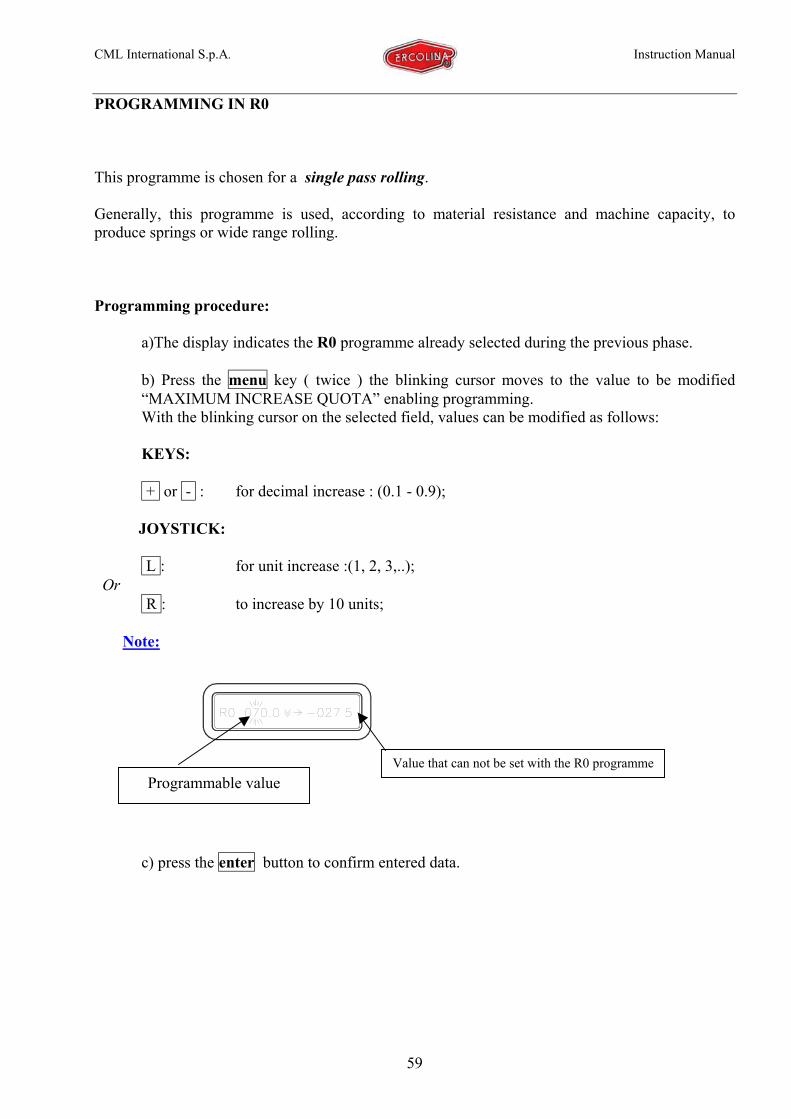
PROGRAMMING IN R0
This programme is chosen for a single pass rolling.
Generally, this programme is used, according to material resistance and machine capacity, toproduce springs or wide range rolling.
Programming procedure:
a)The display indicates the R0 programme already selected during the previous phase.
b) Press the menu key ( twice ) the blinking cursor moves to the value to be modified“MAXIMUM INCREASE QUOTA” enabling programming.With the blinking cursor on the selected field, values can be modified as follows:
KEYS:
+ or - : for decimal increase : (0.1 - 0.9);
JOYSTICK:
L : for unit increase :(1, 2, 3,..); Or
R : to increase by 10 units;
Note:
c) press the enter button to confirm entered data.
Value that can not be set with the R0 programmeProgrammable value
CML International S.p.A. Instruction Manual
60
«
Rolling command sequence using R0 programme:
a) move centre roll to the working area using Comb. 1(green light indicator on: in position);
b) Insert material between rolls;
c) Select the material’s sliding direction using the R and L buttons;
d) Using Comb.2: the centre roll descent is enabled ( the display will show the “ ”indication) and it moves on the material at a “zero quota”;
e) Use the enter key : to confirm the increase value previously programmed;
f) Press the pedal the centre roll penetrates the material according to the value set, (withoutrolling);
g) Remove foot from pedal: orange light indicator on (rolling mode);
a) Press the pedal for the necessary time to perform rolling: when operation is completedrelease pedal..
Note: use the menu key: to further modify the achieved passing quota without removing thecentre roll for a new machine setting.
Ex.:
Part extraction:
a) Use the Comb.1 button: to enable the centre roll ascent (the display will show theindication:“ “) it will reach the maximum working area quota programmed during therelevant phase ( fig. 2 );
b) The part can be removed and the machine is ready for the next rolling operation.
!!WARNING: IN THIS PHASE THE PART IS NOT HELD BY THE ROLLS AND IT CAN FALL. TAKE ALLNECESSARY PRECAUTIONS TO AVOID ANY DANGER.
Modifiable passing quota
CML International S.p.A. Instruction Manual
61
R1…………..R7 PROGRAMMES
These programmes are normally used for rolling requiring high precision and repetition; for thisreason they can bend with programmed increases at multiple passes.To activate these programmes, repeat the previous “ machine setting” procedures
Programming procedure:
a) Press the menu key ( twice ) the blinking cursor moves to the “MAXIMUM INCREASEQUOTA” value, enabling programming (·)
Ex.:
b) Press the enter button to confirm the entered value variation;
c) Press the menu button ( 3 times ) the blinking cursor moves to the “programmable pass
increase”. (·)
d) c) press the enter button to confirm.
Programming is completed.
(·) Note: With the blinking cursor on the selected field, values can be modified as follows:
KEYS:
+ or - for decimal increase (0.1- 0.9) :
JOYSTICK:
L : for unit increase:(1, 2, 3,..):
R : to increase by 10 units:
Programmable passincremental value
Max increase quota. On specific casepress R 3 times
CML International S.p.A. INSTRUCTION MANUAL
63
WORKING AREA
REFERENCE POINT
PART DEFORMATION
Bending RadiusT: distance between lowerrolls/material contact points;F: penetration depth
Comb.1
Comb.2
Comb.3
Comb.4
8xFT
2FR
2
+=
“ROLLING” PHASE
a) Move centre roll to the working area;
b) Insert material between rolls: (fig.1);
c) Select the rolls’ sliding direction using the R and L buttons;
d) Use Comb. 2, to enable the centre roll descent ( ); press the “pedal” until the centre roll reaches the material at a “zero” quota;
e) Remove foot from pedal ;
f) Use the enter key, to confirm the programmed increase value per pass;
g) Press the pedal : material’s rolling on the set direction starts simultaneously to the centre roll descent (press the pedal for the necessary time to performrolling). when operation is completed release pedal;
h) Invert the material’s sliding direction using the R or L buttons;
i) Repeat the “f, g, h” operations sequence until the maximum bow established during programming phase is reached to obtain the desired bending radius;
Note: when work is completed the “display”, will show that the “increase quota of programmed passes” equals the “maximum increase” quota.Ex.:
Note: the “maximum increase quota” value can be corrected or raised without changing the “incremental quota per pass”. To obtain this variation, repeat the“programming procedure”.
Part extraction:
a) Use the Comb. button. 1 : to enable the centre roll ascent (the display will show the “ “ indication ) it will reach the maximum working areaquota programmed during the relevant phase ( fig. 2 );
b) The part can be removed and the machine is ready for the next rolling operation.
!!WARNING: IN THIS PHASE THE PART IS NOT HELD BY THE ROLLS AND IT CAN FALL. TAKE ALL NECESSARY PRECAUTIONS TO AVOID ANY DANGER.
Programmed max.increase quota Programmed pass incremental
quota
