cdma access channel parameters
TRANSCRIPT

Access Channel Parameters

Access Channel ParametersAccess Channel Parameters
Access Channel ?Overview
Access Channel is a Reverse CDMA Channel used by mobile stations for communicating to the base station.
The Access Channel is used by the mobile station to initiate communicat- ion with the base station and to respond to Paging Channel messages.
In additioanlly, the Access Channel may be used to transmit user’s short messages.
The messages transmitted on the Access Channel can be classified into two types, the Request Messages and the Response Messages.
Example of Request Messages:
Origination Message, Registration Message, Order Message, etc.
Example of Response Messages:
Response Message, Order Message, etc.
Access Channel ParametersAccess Channel Parameters
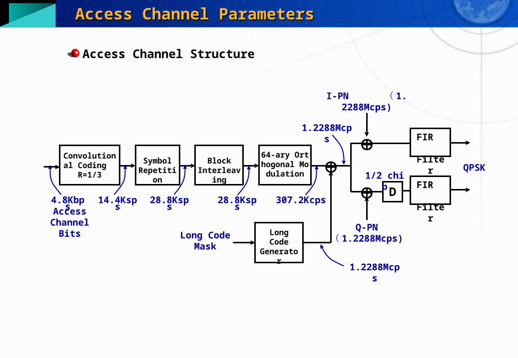
Access Channel Structure
1.2288Mcps
4.8KbpsAccess
Channel Bits
14.4Ksps
Long Code
Generator
Long Code Mask
1.2288Mcps
28.8Ksps 28.8Ksps
64-ary Orthogonal Modul
ation
Convolutional Coding
R=1/3
Symbol Repetition
Block Interleaving
307.2Kcps
D
1/2 chip
FIR Filter
QPSK
I-PN ( 1.2288Mcps)
Q-PN ( 1.2288Mcps)
FIR Filter

Access Channel ParametersAccess Channel Parameters
FeaturesThe mobile station transmits on the Access Channel using a Random Access procedure.
64-ary orthogonal modulation
Spreading and channelizing with Long PN code
Fixed data rate: 4800bps
Frame length: 20ms
Maximum 32 Access Channels shall be supported per Paging Channel
The mobile station supports only one Access Channel.
Long code mask
41 33
32 28 27 25 24 9 8 0
110001111 ACN PCN BASE_ID PILOT_PN
ACN : Access Channel Number (0~31)
PCN : Paging Channel Number (1~7)
BASE_DI : Base Station ID (0~65535)
PILOT_PN : Pilot PN offset index

Access Channel ParametersAccess Channel Parameters
Access Channel Frame Structure
ACH Frame
Access Channel Slot
0.02x[(1+PAM_SZ)+(3+MAX_CAP_SZ)] sec, 96x[(1+PAM_SZ)+(3+MAX_CAP_SZ)] bits
20ms, 96bits
Access Channel Message Capsule
Access Channel Message
MSG_LENGTH
Padding
Message Body CRC
88 x Nf bits
8 x MSG_LENGTH
8bits 2 - 842bits 30bits
. . . . . .
Access Channel Preamble ACH Frame Body T ACH Frame Body T. . .
1+PAM_SZ Frames, 96x(1+PAM_SZ) bits
Nf Frames, 96xNf bits (Not exceeding 3+MAX_CAP_SZ Frames)
Nf: Number of Access Channel frames needed for message transmission
T: Encoder Tail Bits (8bits)
ACH Frame ACH Frame ACH FrameACH Frame
T T

Access Channel ParametersAccess Channel Parameters
Random Access ProcedureOverview
In the CDMA system, the mobile stations use the random access proced-ure to make a low probability of collision among the probes sent by each mobile station.
The mobile station shall begin the access probe transmission at the timing posterior to the start of an access channel slot by a random PN chips.
System Time
Access Channel Slot Access Channel Slot
The actual start of transmission is deferred from the beging of the access channel slot for PN chips.

Access Channel ParametersAccess Channel Parameters
Access Attempt
System Time
Access Probe Sequence 1 Seq 2 Seq 3
Seq MAX_REQ_SEQ (15 max)
Access Attempt
RS RS PD
Request message ready for transmission
Request Attempt
PD PD
PD : Persistence Delay
RS : Random Sequence backoff delay
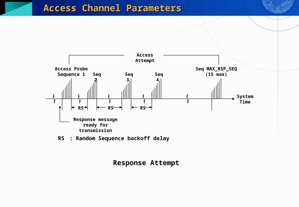
Access Channel ParametersAccess Channel Parameters
System Time
Access Probe Sequence 1 Seq 2 Seq 3 Seq 4
Seq MAX_RSP_SEQ (15 max)
Access Attempt
RS RS RS
Response message ready for transmission
Response Attempt
RS : Random Sequence backoff delay

Access Channel ParametersAccess Channel Parameters
System Time
IP (Initial Power)
Access Probe 1 + NUM_STEP
(16 max)
Access Probe Sequence
TA RT
PI
Select Access Channel (RA), initialize transmit power
Access Probe Sequence
RT
Access Probe 3
Access Probe 2
Access Probe 1
TA TA
PI
PI : Power Increment
TA : Acknowlogment response timeout
RT : Probe backoff
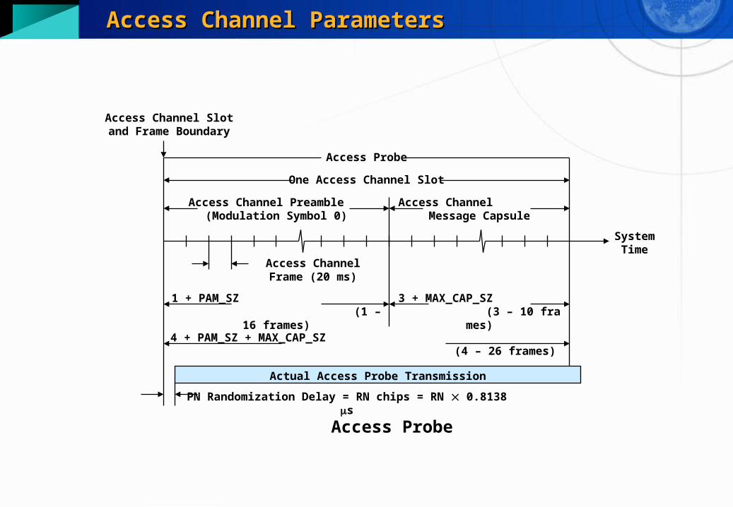
Access Channel ParametersAccess Channel Parameters
System Time
Access Channel Slot and Frame Boundary
Access Probe
PN Randomization Delay = RN chips = RN 0.8138 s
Access Probe
One Access Channel Slot
Access Channel Preamble (Modulation Symbol 0)
Access Channel Message Capsule
Access Channel Frame (20 ms)
1 + PAM_SZ (1 – 16 frames)
3 + MAX_CAP_SZ (3 – 10 frames)
4 + PAM_SZ + MAX_CAP_SZ (4 – 26 frames)
Actual Access Probe Transmission

Access Channel ParametersAccess Channel Parameters
Vari-able
Name Generation Range Units
IP Initial Open-loop PowerIP = – mean input power (dBm) + offset power + NOM_PWR – 16×NOM_PWR_EXT + INIT_PWR + interference correction
dBm
PD Persistence DelayDelay continues slot-by-slot until persistence
test (run every slot) passes.- slots
PI Power IncrementPI = PWR_STEPs + change in mean input power + change in interference correction
dB
RA Access Channel NumberRandom between 0 and ACC_CHANs; generated before every access probe sequence or every access probe.
0~31 -
RN PN Randomization DelayHash using ESN between 0 and 2PROBE_PN_RAN – 1; generated once at the beginning of each access sub-attempt.
0~511 chips
RS Sequence BackoffRandom between 0 and 1 + BKOFF; generated before every sequence (except the first sequence).
0~16 slots
RT Probe BackoffRandom between 0 and 1 + PROBE_BKOFF; generated before subsequent probes.
0~16 slots
TA Ack Response TimeoutTA = 80 (2 + ACC_TMO); timeout from end of slot
160~1360 ms

Access Channel ParametersAccess Channel Parameters
Parametersmax_req_seq
Maximum number of access probe sequences for a request.
Range: 1~15 Default: 2
backoff
Backoff range between access probe sequences.
Range: 0~15 Default: 5
max_rsp_seq
Maximum number of access probe sequences for a response.
Range: 1~15 Default: 2
nominal_pwr
Nominal transmit power offset.
Range: - 8 ~ +7dB
Access Channel ParametersAccess Channel Parameters
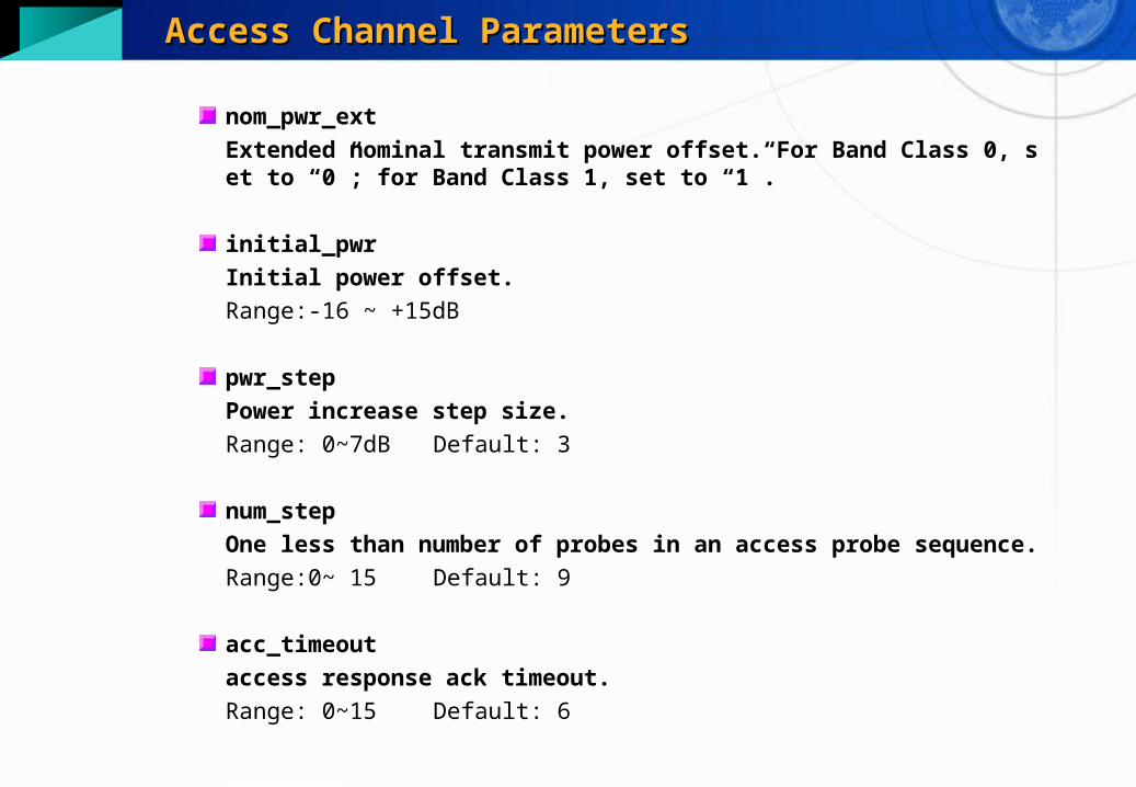
nom_pwr_ext
Extended nominal transmit power offset. For Band Class 0, set to “0”; for Band Class 1, set to “1”.
initial_pwr
Initial power offset.
Range:-16 ~ +15dB
pwr_step
Power increase step size.
Range: 0~7dB Default: 3
num_step
One less than number of probes in an access probe sequence.
Range:0~ 15 Default: 9
acc_timeout
access response ack timeout.
Range: 0~15 Default: 6
Access Channel ParametersAccess Channel Parameters
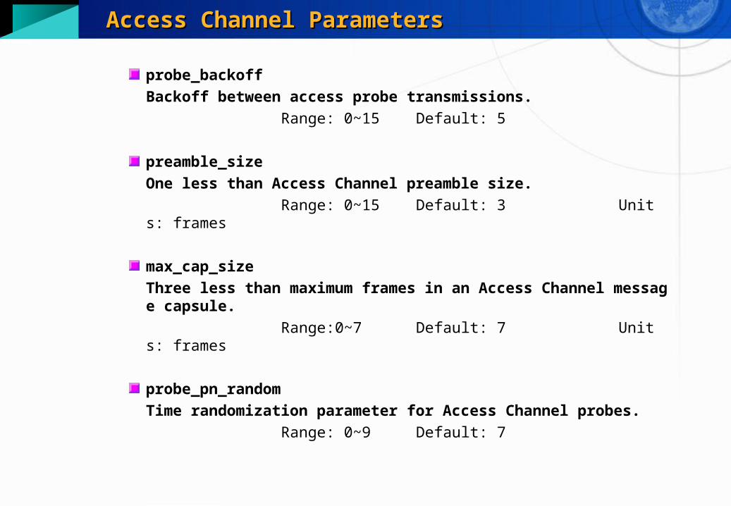
probe_backoff
Backoff between access probe transmissions.
Range: 0~15 Default: 5
preamble_size
One less than Access Channel preamble size.
Range: 0~15 Default: 3 Units: frames
max_cap_size
Three less than maximum frames in an Access Channel message capsule.
Range:0~7 Default: 7 Units: frames
probe_pn_random
Time randomization parameter for Access Channel probes.
Range: 0~9 Default: 7
Access Channel ParametersAccess Channel Parameters
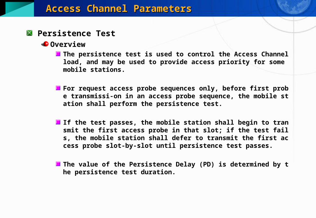
Persistence TestOverview
The persistence test is used to control the Access Channel load, and may be used to provide access priority for some mobile stations.
For request access probe sequences only, before first probe transmissi-on in an access probe sequence, the mobile station shall perform the persistence test.
If the test passes, the mobile station shall begin to transmit the first access probe in that slot; if the test fails, the mobile station shall defer to transmit the first access probe slot-by-slot until persistence test passes.
The value of the Persistence Delay (PD) is determined by the persistence test duration.
Access Channel ParametersAccess Channel Parameters
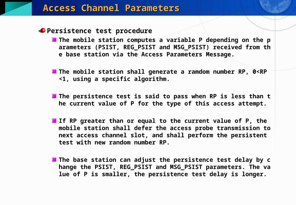
Persistence test procedureThe mobile station computes a variable P depending on the parameters (PSIST, REG_PSIST and MSG_PSIST) received from the base station via the Access Parameters Message.
The mobile station shall generate a ramdom number RP, 0<RP<1, using a specific algorithm.
The persistence test is said to pass when RP is less than the current value of P for the type of this access attempt.
If RP greater than or equal to the current value of P, the mobile station shall defer the access probe transmission to next access channel slot, and shall perform the persistent test with new random number RP.
The base station can adjust the persistence test delay by change the PSIST, REG_PSIST and MSG_PSIST parameters. The value of P is smaller, the persistence test delay is longer.

Access Channel ParametersAccess Channel Parameters
Variable P calculationIf the Access Channel request is a registration, P shall be computed by
If the Access Channel request is a message transmission, P shall be computed by

Access Channel ParametersAccess Channel Parameters
If the Access Channel request is other than a registration or a message transmission, P shall be computed by
where ACCOLCp (0~15) is access overload class indicator.
The access overload class 0 ~ 9 are assigned to commercial mobile stations, the access overload class 10 is assigned to test mobile station, the access overload class 11 is assigned to emergency mobile station, and the access overload class 12~15 are reserved.
Access Channel ParametersAccess Channel Parameters
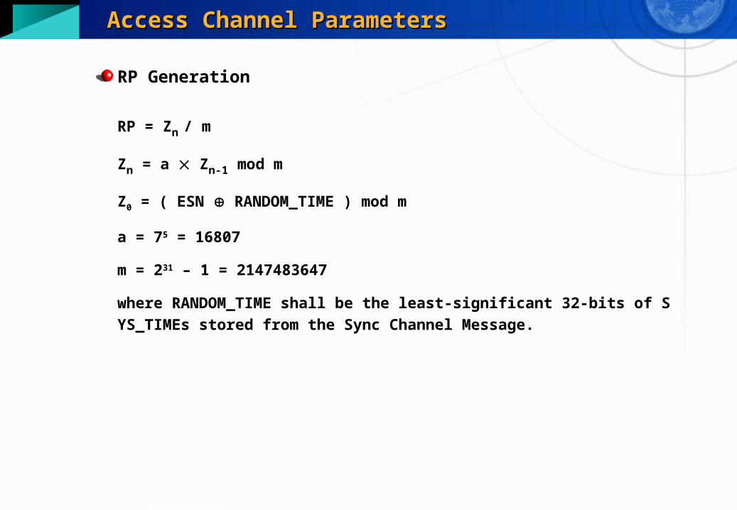
RP Generation
RP = Zn / m
Zn = a Zn-1 mod m
Z0 = ( ESN RANDOM_TIME ) mod m
a = 75 = 16807
m = 231 – 1 = 2147483647
where RANDOM_TIME shall be the least-significant 32-bits of SYS_TIMEs stor
ed from the Sync Channel Message.

Access Channel ParametersAccess Channel Parameters
Parameterspsist_0_9
Persistence for overload classes 0~9.
Range: 0~63 Default: 0
psist_10
Persistence for overload class 10 (test mobile stations).
Range: 0~7 Default: 0
psist_11
Persistence for overload class 10 (emergency mobile stations).
Range: 0~7 Default: 0
psist_12 ~ 15
Persistence for overload class 12~15 (Reversed).
Range: 0~7 Default: 0
Access Channel ParametersAccess Channel Parameters
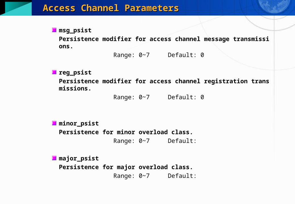
msg_psist
Persistence modifier for access channel message transmissions.
Range: 0~7 Default: 0
reg_psist
Persistence modifier for access channel registration transmissions.
Range: 0~7 Default: 0
minor_psist
Persistence for minor overload class.
Range: 0~7 Default:
major_psist
Persistence for major overload class.
Range: 0~7 Default:

Access Channel ParametersAccess Channel Parameters
critical_psist
Persistence for critical overload class.
Range: 0~7 Default: