ccr rule 40cfr §257.60 – 64 location …...1100 s. mccaslin blvd, suite 150 superior, colorado...
TRANSCRIPT

CCR RULE 40CFR §257.60 – 64
LOCATION RESTRICTIONS CRITERIA
CERTIFICATION REPORT
ASH DISPOSAL FACILITY
COMANCHE STATION
PUEBLO, COLORADO
Prepared For:
Public Service Company of Colorado (PSCo)
Prepared by:
Tetra Tech
1100 S. McCaslin Blvd, Suite 150
Superior, Colorado 80027
Submitted: September 8, 2017
LOCATION RESTRICTION CERT RPT FINAL 090817.DOCXTETRA TECH
Comanche Station i
TABLE OF CONTENTS
List of Abbreviations and Acronyms .......................................................................................... ii
Professional Engineer Certification ........................................................................................... iii
1.0 Introduction .......................................................................................................................... 1
1.1 GENERAL INFORMATION.............................................................................................. 1
1.2 Type of Facility ............................................................................................................ 1
2.0 Location Restrictions ........................................................................................................... 2
2.1 Placement Above The Uppermost Aquifer 40 CFR §257.60................................... 2
2.2 Wetlands 40 CFR §257.61 .......................................................................................... 3
2.3 Fault Areas 40 CFR §257.62 ...................................................................................... 4
2.4 Seismic Impact Zones 40 CFR §257.63 ..................................................................... 5
2.5 Unstable Areas 40 CFR §257.64 ................................................................................ 5
3.0 Summary ............................................................................................................................... 7
4.0 References ............................................................................................................................. 8
LIST OF FIGURESFigure 1-1. Comanche Site Map
Figure 2-1. Geotechnical Boring Location Map
Figure 2-2. Monitoring Well Location Map
Figure 2-3. Surface Water Features Within 2-Mile Radius

LOCATION RESTRICTION CERT RPT FINAL 090817.DOCXTETRA TECH
Comanche Station ii
LIST OF ABBREVIATIONS AND ACRONYMS
ADF Ash Disposal Facility
AMSL Above Mean Sea Level
CCR Coal Combustion Residuals
CFR Code of Federal Regulations
CLOMR Conditional Letter of Map Revision
Corp U.S. Army Corps of Engineers
EPA U.S. Environmental Protection Agency
FEMA Federal Emergency Management Agency
FIRM Flood Insurance Rate Map
FM Formation
MW Megawatts
NFIP National Flood Insurance Program
RCRA Resource Conservation and Recovery Act
PSCo Public Service Company of Colorado
SFHA Special Flood Hazard Area


LOCATION RESTRICTION CERT RPT FINAL 090817.DOCX TETRA TECHComanche Station 1
1.0 INTRODUCTION
This Location Restriction Certification report has been prepared for the Ash Disposal
Facility (ADF) located at Public Service Company of Colorado’s (PSCo’s) Comanche Station
(the Site). This report conforms to 40 Code of Federal Regulations (CFR) Part 257. This report
was prepared to address the new federal coal combustion residual (CCR) regulations for disposal
of ash under subtitle D of the Resource Conservation and Recovery Act (RCRA). The final rule
was published in the Federal Register, Volume 80 Number 74 on April 17, 2015, and became
effective on October 19, 2015.
1.1 GENERAL INFORMATION
Comanche Station is located west of Lime Road approximately 3 miles south of Colorado
Highway 50 in Pueblo County, Colorado (Figure 1-1). The facility is located in the west half of
Section 20, Township 21 South, Range 64 West of the 6th Principal Meridian, Pueblo County,
Colorado. The land-surface elevations range from approximately 4,830 feet above mean sea
level (amsl) in the southwest and northwest corners of the Site to approximately 4,800 feet amsl
in the southeast corner of the Site. The Site, including the Ash Disposal Facility (ADF), was
annexed by the City of Pueblo in 2005. The facility is located in an area zoned I-3 (Heavy
Industrial) by the City of Pueblo Zoning Department. Ordinances with the City of Pueblo allow
solid waste disposal in an industrial zone within city limits subject to review and issuance of a
Special Use Permit. The Comanche ADF operates under an approved Special Use Permit (ZBA
Case # 058-2005).
Comanche Station is a coal-fired plant that consists of three units (Units 1, 2 and 3) that
burn Powder River Basin coal. Unit 1 was built in 1973 and is rated at 350 megawatts (MW),
Unit 2 was built in 1975 and is rated at 350 MW, and Unit 3 was built in 2010 and is rated at 750
MW. The primary Site features are shown on Figure 1-1.
1.2 TYPE OF FACILITY
The ADF is an approximately 280 acre engineered ash monofill consisting of eight
permitted disposal cells. Cell 1 was constructed in 2005 prior to the promulgation of the federal
CCR regulations. Cell 2 East is planned for construction in 2017. Approximately 38.7 acres of
the ADF will be used for surface water control structures, access roads, and borrow area. The
wastes accepted at the ADF consist of coal ash, water treatment sludge, process water pond
sediment, coal impurities, and excavation soils.

LOCATION RESTRICTION CERT RPT FINAL 090817.DOCX TETRA TECHComanche Station 2
2.0 LOCATION RESTRICTIONS
2.1 PLACEMENT ABOVE THE UPPERMOST AQUIFER 40 CFR §257.60
The 40 CFR §257.60 places restrictions on locating the base of a CCR landfill or surface
impoundment within 5 feet of the uppermost aquifer. It states the following:
“New CCR landfills, existing and new CCR surface impoundments, and all lateral expansions of CCR units must be constructed with a base that is located no less than 1.52 meters (five feet) above the upper limit of the uppermost aquifer, or must demonstrate that there will not be an intermittent, recurring, or sustained hydraulic connection between any portion of the base of the CCR unit and the uppermost aquifer due to normal fluctuations in groundwater elevations (including the seasonal high water table).”
Compliance with Uppermost Aquifer Restriction
The base of the ADF will be significantly greater than 5 feet above the uppermost aquifer beneath the Site. The Dakota Sandstone is the uppermost aquifer, which is at a depth of greater than 1,450 feet beneath the ADF.
A discussion of the local hydrogeology and uppermost aquifer is provided below.
Local Hydrogeology
The hydrogeologic setting beneath this Site is naturally protective of the groundwater and
surface water features. The hydrogeologic conceptual model for the Site is discussed below.
The Comanche Station is underlain by up to 30 feet of unconsolidated colluvium
consisting of stiff clays and silts (D&O Plan, 2005). Underlying the colluvium is 1,450 feet of
low-permeability shale deposits. The low-permeability shale deposits consist of primarily
bentonitic shales, with some minor chalk and limestone deposits interbedded within the shale.
Underlying the 1,450 feet of shale deposits is the Dakota Sandstone Formation (Fm), which is
the uppermost aquifer in this area.
Low-permeability shale deposits beneath the Site form an effective barrier to mitigate
vertical migration of infiltration water. The approximately 1,450 feet of low-permeability shale
deposits consist of the following (Scott, 1969): 1) 230 feet of shale comprising the lower portion
of the Pierre Shale Fm; 2) 740 feet of chalk and shale deposits of the Niobrara Fm; 3) 230 feet of
Carlile Shale; 4) 150 feet of shale and limestone comprising the Greenhorn Fm; and 5) 100 feet
of Graneros Shale.
LOCATION RESTRICTION CERT RPT FINAL 090817.DOCX TETRA TECHComanche Station 3
Uppermost Aquifer
The first regional potentiometric surface is in the Dakota Sandstone, which is isolated
from the ADF by 1,450 feet of shales of the Pierre and Niobrara formations. The alluvial
aquifers associated with the Arkansas River, the St. Charles River, and Salt Creek do not extend
beneath the facility, and a laterally extensive shallow groundwater system is not present in the
colluvium deposits beneath the Site. Poor quality perched water has been encountered in the
Pierre Shale at a depth of approximately 35 feet beneath the Site. In addition, the long-term
historical operation of surface water impoundments at the Site may have resulted in some
localized perched water in the immediate vicinity of the impoundments; however, this perched
water appears to be laterally discontinuous.
The southwestern portion of the ADF (Cell 3) is underlain by a sand and gravel layer
located at a depth of 30 to 40 feet below ground surface. Perched groundwater, which is not
considered an aquifer, was found at a depth of 35 feet in this layer. The base of Cell 3 will be
approximately 20 feet above the perched water in this layer (D&O Plan, 2005).
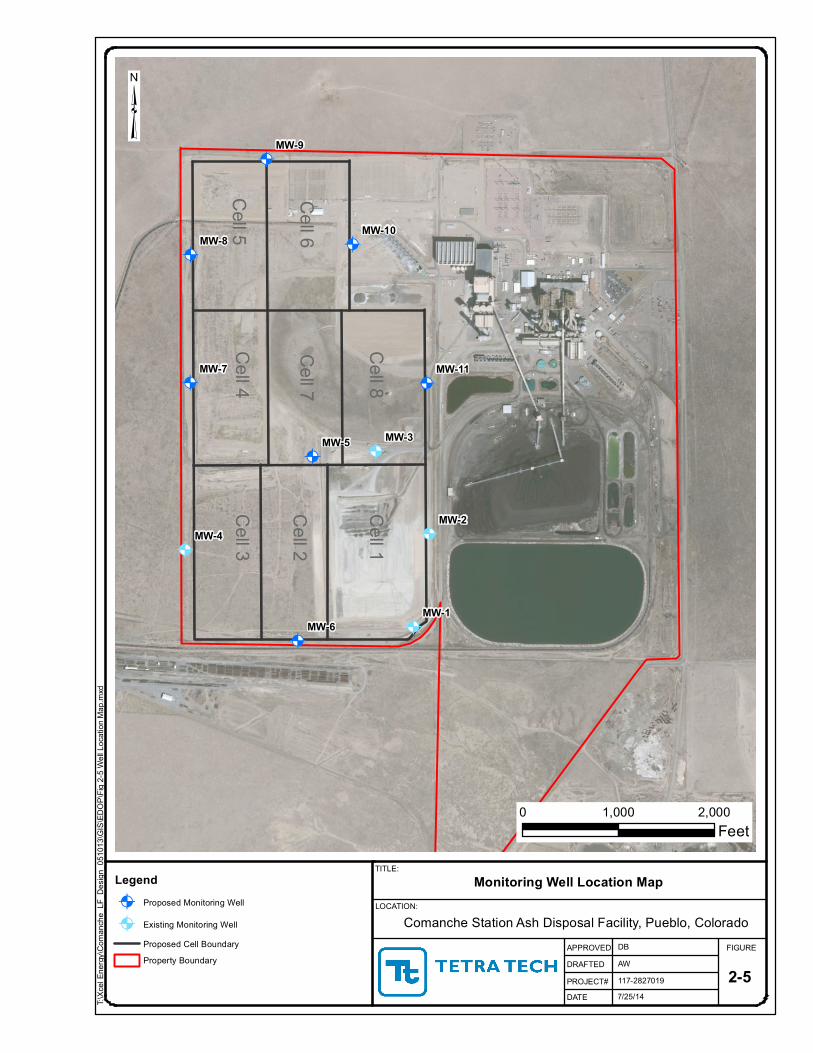
Four groundwater monitoring wells were installed in 1987 in the shallow colluvium
deposits around the ADF to monitor for perched groundwater conditions (Figure 2-2).
Monitoring wells MW-1 through MW-3 encountered bedrock at a depth of approximately 7 to 10
feet, whereas MW-4 encountered bedrock at a depth of approximately 27 feet. Over the
approximately 30 years of monitoring, only one of the four wells periodically has contained
water (MW-3); the remaining three wells have been essentially dry over this same time period.
Monitoring well MW-3 is located on the northern end of Cell 1 in a topographic surface
depression that periodically ponds runoff water during precipitation events. The sporadic
appearance of approximately 1 to 2.5 feet of water in MW-3 is likely due to infiltration of
surface water runoff during high precipitation events.
2.2 WETLANDS 40 CFR §257.61
The 40 CFR §257.61 places restrictions on locating CCR landfills and surface impoundment in areas designated as wetlands. It states the following:
“New CCR landfills, existing and new CCR surface impoundments, and all lateral expansions of CCR units must not be located in wetlands, as defined in § 232.2 of this chapter, unless the owner or operator demonstrates by the dates specified in paragraph (c) of this section that the CCR unit meets the requirements of paragraphs (a)(1) through (5) of this section.”
Compliance with Wetlands Restriction
Based on Site reconnaissance, the ADF is not located within or proximate to any
wetlands.

LOCATION RESTRICTION CERT RPT FINAL 090817.DOCX TETRA TECHComanche Station 4
Wetlands Definition
The definition of wetlands as used by the U.S. Army Corps of Engineers (Corps) and the
U.S. Environmental Protection Agency (EPA) since the 1970s for regulatory purposes is the
following (http://www.usace.army.mil/Portals/2/docs/civilworks/regulatory/rw_bro.pdf):
"Wetlands are areas that are inundated or saturated by surface or ground water at a
frequency and duration sufficient to support, and that under normal circumstances do
support, a prevalence of vegetation typically adapted for life in saturated soil conditions.
Wetlands generally include swamps, marshes, bogs, and similar areas."
Local Hydrology
The ADF sits on a high point between the St. Charles River and Salt Creek drainages
(Figure 2-3). The facility is not within the flood plain of either drainage; however, an unnamed
depression is present within the footprint of the ADF. This area collects precipitation from the
upland area between the St. Charles River and Salt Creek. The depression is designated a
Special Flood Hazard Area (SFHA) by the Federal Emergency Management Agency (FEMA).
A SFHA is an area that will be inundated by a storm having a 1-percent chance of being equaled
or exceeded in any given year. Based on the Conditional Letter of Map Revision (CLOMR)
permit application submitted by Xcel Energy on May 23, 2006, the 100-year flood volume
draining to the SFHA is 57.3 acre-ft. The storage capacity of the SFHA will be replaced by
perimeter ponds when ADF construction intercepts and displaces the SFHA.
The December 7, 2006, FEMA response (U.S. Department of Homeland Security, 2006)
to the CLORM application stated that the proposed ADF project meets the minimum floodplain
management criteria of Part 65 of the National Flood Insurance Program (NFIP). The FEMA
response also stated that as a result of the project, the City of Pueblo Flood Insurance Rate Map
(FIRM) will be revised to remove the existing unnamed ponding area and storm water Pond 1
will be shown as containing the SFHA.
2.3 FAULT AREAS 40 CFR §257.62
The 40 CFR §257.62 places restrictions on locating CCR landfills and surface impoundment in close proximity to active fault areas. It states the following:
“New CCR landfills, existing and new CCR surface impoundments, and all lateral expansions of CCR units must not be located within 60 meters (200 feet) of the outermost damage zone of a fault that has had displacement in Holocene time unless the owner or operator demonstrates by the dates specified in paragraph (c) of this section that an alternative setback distance of less than 60 meters (200 feet) will prevent damage to the structural integrity of the CCR unit.”

LOCATION RESTRICTION CERT RPT FINAL 090817.DOCX TETRA TECHComanche Station 5
Compliance with Fault Areas Restriction
There are no known Holocene faults present on the site or within 200 feet of the Site
(Morgan et al., 2012).
2.4 SEISMIC IMPACT ZONES 40 CFR §257.63
The 40 CFR §257.63 places restrictions on locating CCR landfills and surface impoundment in seismic impact zones. It states the following:
“New CCR landfills, existing and new CCR surface impoundments, and all lateral expansions of CCR units must not be located in seismic impact zones unless the owner or operator demonstrates by the dates specified in paragraph (c) of this section that all structural components including liners, leachate collection and removal systems, and surface water control systems, are designed to resist the maximum horizontal acceleration in lithified earth material for the site.”
The Federal Register Volume 80 No. 74 defines a seismic impact zone as the following:
“A Seismic impact zone means an area having a 2% or greater probability that the maximum expected horizontal acceleration, expressed as a percentage of the earth’s gravitational pull (g), will exceed 0.10 g in 50 years.”
Compliance with Seismic Impact Zones Restriction
The ADF and Pueblo areas are not considered to be in active seismic zones (U.S.
Geological Survey, 2014), as defined as an area having a 2 percent or greater probability
that the peak ground acceleration will exceed 10 percent of standard gravity in 50 years.
2.5 UNSTABLE AREAS 40 CFR §257.64
The 40 CFR §257.64 places restrictions on locating CCR landfills and surface impoundment in unstable areas. It states the following:
“An existing or new CCR landfill, existing or new CCR surface impoundment, or any lateral expansion of a CCR unit must not be located in an unstable area unless the owner or operator demonstrates by the dates specified in paragraph (d) of this section that recognized and generally accepted good engineering practices have been incorporated into the design of the CCR unit to ensure that the integrity of the structural components of the CCR unit will not be disrupted. The owner or operator must consider all of the following factors, at a minimum, when determining whether an area is unstable (1) On-site or local soil conditions that may result in significant differential settling; (2) On-site or local geologic or geomorphologic features; and (3) On-site or local human-made features or events (both surface and subsurface).”

LOCATION RESTRICTION CERT RPT FINAL 090817.DOCX TETRA TECHComanche Station 6
Compliance with Unstable Areas Restriction
Based on Site reconnaissance and the geotechnical investigations (Figure 2-1), there
is no evidence of unstable conditions that may result in differential settling resulting from
geologic/geomorphologic features and/or man-made features at the Site.
The ADF is located on relative flat ground not subject to mass wasting. Swelling soils
are widespread in Colorado, and are potentially present at the Site and must be addressed in
design and construction of on-Site facilities. However, these conditions are not considered
widespread or problematic.
LOCATION RESTRICTION CERT RPT FINAL 090817.DOCX TETRA TECHComanche Station 7
3.0 SUMMARY
The Xcel Energy/PSCo Comanche ADF meets and/or exceeds all location restriction
requirements detailed in 40 CFR Part 257:
40 CFR §257.60 -- Uppermost Aquifer: The base of the ADF will be greater than 5 feet
above the uppermost aquifer beneath the Site;
40 CFR §257.61 – Wetlands: The ADF is not located within or proximate to any
jurisdictional wetland;
40 CFR §257.62 -- Fault Areas: There are no known Holocene faults present on the
site or within 200 feet of the Site;
40 CFR §257.63 -- Seismic Impact Zones: The ADF and Pueblo areas are not considered to be
in active seismic zones; and
40 CFR §257.64 -- Unstable Areas: There is no evidence of unstable areas due to local
soil conditions that may result in differential settling
due to geologic/geomorphologic features and/or
man-made features at the Site.

LOCATION RESTRICTION CERT RPT FINAL 090817.DOCX TETRA TECHComanche Station 8
4.0 REFERENCES
Morgan, M. L., Matthews, V., and Heerschap, L., 2012. Colorado Earthquake Map Server:
http://dnrwebcomapg.state.co.us/CGSOnline/, accessed on 24 Dec. 2014.
Scott, G.R., 1969. General and engineering geology of the northern part of Pueblo, Colorado.
United States Geological Survey Bulletin 1262, 131p. 1969.
U.S. Department of Homeland Security, 2006. Federal Emergency Management Agency
(FEMA). Letter to Pueblo City Council in Response to Case No.: 06-08-B503R.
7 Dec. 2006.
U.S. Geologic Survey, 2014. National Seismic Hazard Map: Two-percent probability of
exceedance in 50 years map of peak ground acceleration. 2014.
Xcel Energy, 2005. Comanche Station Coal Ash Disposal Facility Design and Operations Plan.
24 Aug. 2005.
Xcel Energy, 2006. Re: XCEL Comanche Plant – CLOMR Permit Application. 23 May. 2006.

LOCATION RESTRICTION CERT RPT FINAL 090817.DOCXTETRA TECH
Comanche Station
FIGURES

Raw Water
Storage Pond
Stormwater Pond
Polishing
Pond
Settling
Pond East
Bottom
Ash Pond
Unit 3 Treated
Water
Pond
Unit 1 & 2 Treated
Water
Pond
Process
Water Pond
Ash Disposal
Facility
Stormwater Pond
Coal Pile
River Discharge
Diversion Pond
S
t
.
C
h
a
r
l
e
s
R
i
v
e
r
Settling
Pond West
Comanche Site Map
Pueblo, Colorado
N
COLORADO
DENVER
SITE
Approximate PSCo
Property Boundary
Explanation:
Ash Disposal Facility
Boundary

8/8/14
HF117-2827019
DB
Comanche Station Ash Disposal Facility, Pueblo, Colorado
Geotechnical Boring Location Map
Boring 2
Boring 1
Boring 3
Boring 9
Boring 8
Boring 5
Boring 7
Boring 6
Boring 4
Boring 11
Boring 10
Boring 13
Boring 12
TITLE:
LOCATION:
APPROVEDDRAFTEDPROJECT#DATE
FIGURE
Legend2013 Geotechnical Boring Location2014 Geotechnical Boring LocationProposed Cell BoundaryProperty Boundary
0 500 1,000Feet
³T:\
Xcel
Energ
y\Com
anch
e_LF
_Des
ign_0
5101
3\GIS\
EDOP
\Fig 2
-3 Ge
otech
Borin
g Map
.mxd
Cell 5
Cell 6
Cell 4
Cell 7
Cell 8
Cell 3
Cell 2
Cell 1
2-3
7/25/14
AW117-2827019
DB
Comanche Station Ash Disposal Facility, Pueblo, Colorado
Monitoring Well Location Map
@A
@A
@A
@A
@A
@A
@A
@A
@A
@A
@A
MW-4
MW-3
MW-2
MW-1
MW-9
MW-8
MW-7
MW-6
MW-5
MW-11
MW-10
TITLE:
LOCATION:
APPROVEDDRAFTEDPROJECT#DATE
FIGURE
Legend@A Proposed Monitoring Well
@A Existing Monitoring WellProposed Cell BoundaryProperty Boundary
0 1,000 2,000Feet
³T:\
Xcel
Energ
y\Com
anch
e_LF
_Des
ign_0
5101
3\GIS\
EDOP
\Fig 2
-5 We
ll Loc
ation
Map
.mxd
Cell 5
Cell 6
Cell 4
Cell 7
Cell 8
Cell 3
Cell 2
Cell 1
2-5

7/29/14
AW117-2827019
DB
Comanche Station Ash Disposal Facility, Pueblo, Colorado
Surface Water Features Within 2-Mile Radius
St.Charles River
Salt C
reek
TITLE:
LOCATION:
APPROVEDDRAFTEDPROJECT#DATE
FIGURE
0 2,500 5,000Feet
³T:\
Xcel
Energ
y\Com
anch
e_LF
_Des
ign_0
5101
3\GIS\
EDOP
\Fig 2
-4 Su
rface
Wate
r Fea
tures
with
in 2 m
iles.m
xd
LegendAsh Disposal Facility BoundaryProperty Boundary
2-4