cat.no. b04-18-j kj91 92 intrinsically safe pressure...
TRANSCRIPT

Cat.No. B04-18-J
KJ91
KJ92
*25.4mm conversion fitting supplied as option.
Features of sensor
Compact size and light-weight with the same appearance and operability as non-intrinsically safe GC51 and GC52.Adjustable indication and output scaling are available. Breakthrough readability with LED-backlit LCDBecause the insulated safety barrier is used, Type A intrinsic safety ground work is unnecessary.
They are two types of 2-wire intrinsically safe pressure and differential transmitter, the GC51 based product utilizing SS sensor and GC52 based product utilizing SC sensor. Make sure to use with insulated safety barrier. It can be used in (ZONE 0) place where potentially explosive gas always exists. It conforms to IEC based intrinsically safe specification. (Explosion class: Exia ⅡC T4)In combination with non-intrinsically safe GC51/GC52, it can be used in a wide range of industrial process measurements (Low pressure to high pressure).
KJ91 Pressure Transmitter KJ92 Differential Pressure Transmitter
Silicon diaphragm
Upper glass plate
Lower glass plate
Electrodes
SC Sensor
Actualsize
DiaphragmSUS316L
Silicone oil
SUS316
Semiconductor Evaporated type (SS) Sensor
The semiconductor evaporated type (SS) sensor, which ability has been proven in various industrial fields, has an integral construction from the semiconductor strain gauge part and sensing part to pressure connection part, and no adhesives or corrosive materials are used. It helps for superior durability and stability.
Silicon Capacitance (SC) Sensor
Since the sensor section contains a sealed-in silicon capacitance (SC) sensor formed by micromachining and the wetted parts consist of a stainless steel diaphragm, it handles a wide range of medium and can measure fine differential pressure with high reliability and high sensitivity.
[KJ92][KJ91]
*25.4mm conversion fitting supplied as option.
SS Sensor
Order separately for recommended safety barrier.If using a barrier other than recommended barrier, strictly observe the "Safety Maintenance Rating".
KJ91・92Intrinsically Safe Pressure & Differential Pressure Transmitter
KJ91 is availablefor hydrogenapplication.
Features
Overview

Standard KJ91 Pressure Transmitter
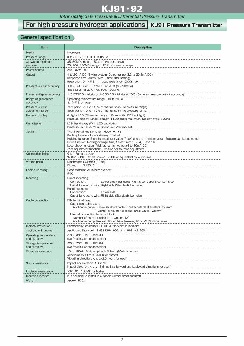
General specification
Item DescriptionGas or Liquid (Compatible with wetted parts) For hydrogen application requiring 35MPa or higher, please consider “High pressure hydrogen application.”-0.1 to 0.1, 0.2, 0.3, 0.5, 1MPa0 to 0.3, 0.5, 1, 2, 3.5, 5, 10, 20, 35, 50, 70, 100, 120MPa200% of pressure range(150% for 35 and 50MPa range 120% for 70, 100 and 120MPa)24V DC±10%4 to 20mA DC (2 wire system, Output range: 3.2 to 20.8mA DC)Response time: 30ms (With 1 time filter setting)Resolution: 0.1%F.S. Load resistance: 500Ω max.±0.25%F.S. or ±0.5%F.S. at 23 (0.5 to 50MPa)±0.5%F.S. at 23 (0.3MPa or lower) (70MPa or higher)
Operating temperature range (-10 to 60)±1%F.S. or lowerZero point: -10 to 110% of the full span (To pressure range)Span point: -10 to 110% of the full span (To pressure range)
±(0.25%F.S.+1digit) or ±(0.5%F.S.+1digit) at 23 (Same as pressure output accuracy)
6 digits LCD (Character height: 10mm, with LED backlight)Pressure display, Linear display: 4 LCD digits maximum, Display cycle 500msLCD bar display (With LED backlight)Pressure unit: kPa, MPa, Linear unit: Arbitrary setWith internal key switches (Mode, , )Scaling function: Linear display / outputHolding function: Both the maximum value (Peak) and the minimum value (Bottom) can be indicatedFilter function: Moving average time, Select from 1, 2, 4, 8 and 16Loop check function: Arbitrary setting output (4 to 20mA DC)Zero adjustment function: Pressure sensor zero adjustmentRc1/4 (50MPa or lower, standard) Rc1/2 (With Rc1/4+FJ10-973, option) G3/8B (With Rc1/4+FJ12-373, option) G1/2B (With Rc1/4+FJ12-473, option)G1/4 Female screw (Option)Diaphragm: SUS630 (17-4PH) High corrosion resistant use (Co-Ni alloy)Fitting: SUS316Casing material: Aluminum die castIP65 10MPa or higherEquivalent to IP65 5MPa or lower With vent holeDirect mounting Connection: Lower side (Standard), Right side, Upper side, Left side Outlet for electric wire: Right side (Standard), Left sidePanel mounting Connection: Lower side Outlet for electric wire: Right side (Standard), Left sideDIN terminal type: Outlet port cable gland Applicable cable: 2 wire shielded cable Sheath outside diameter 6 to 9mm (Center conductor sectional area: 0.5 to 1.25mm2) Internal connection terminal block Number of poles: 4 poles (+, -, Ground, NC) Applicable crimp terminal: Round bare terminal, R1.25-3 (Nominal size)Connector type: TC1108-12A10-7F (Water proof type) (Made by Tajimi Electronics Co., Ltd.)
-10 to 60, 35 to 85%RH(No freezing or condensation)
Applicable Standard EN61326/1997, A1/1998, A2/2001Permanently stored by EEP-ROM (Nonvolatile memory)
-20 to 70, 35 to 85%RH(No freezing or condensation)
Approx. 520g (Direct mounting: DIN terminal type)Approx. 660g (Direct mounting: Connector type)
10 to 150Hz, Multi-amplitude 0.7mm (60Hz or lower)Acceleration: 50m/s2 (60Hz or higher)Vibrating direction: x, y, z (2.5 hours for each)Impact acceleration: 100m/s2Impact direction: x, y, z (3 times into forward and backward directions for each)50V DC 100MΩ or higherIt is possible to install in outdoors (Avoid direct sunlight)
This product is certified by type approval of NK (Nippon Kaiji Kyokai).(Type Approval No. 08T602)
Media
Pressure range
Allowable maximumpressurePower sourceOutput
Pressure output accuracy
Pressure display accuracyRange of guaranteedaccuracyPressure outputadjustment rangeNumeric display
Unit display
Setting
Connection fitting
Wetted parts
Enclosure rating
Mounting
Cable connection
Memory protection
Operating temperatureand humidity
Applicable Standard
Storage temperatureand humidityVibration resistance
Shock resistance
Insulation resistanceMounting locationWeight
KJ91・92Intrinsically Safe Pressure & Differential Pressure Transmitter
2
For high pressure hydrogen applications KJ91 Pressure Transmitter
Item Description
KJ91・92Intrinsically Safe Pressure & Differential Pressure Transmitter
Hydrogen0 to 35, 50, 70, 100, 120MPa35, 50MPa range: 150% of pressure range70, 100, 120MPa range: 120% of pressure range24V DC±10%4 to 20mA DC (2 wire system, Output range: 3.2 to 20.8mA DC)Response time: 30ms (With 1 time filter setting)Resolution: 0.1%F.S. Load resistance: 500Ω max.±0.25%F.S. or ±0.5%F.S. at 23 (35, 50MPa)±0.5%F.S. at 23 (70, 100, 120MPa)
Operating temperature range (-10 to 60)±1%F.S. or lowerZero point: -10 to 110% of the full span (To pressure range)Span point: -10 to 110% of the full span (To pressure range)
±(0.25%F.S.+1digit) or ±(0.5%F.S.+1digit) at 23 (Same as pressure output accuracy)
6 digits LCD (Character height: 10mm, with LED backlight)Pressure display, Linear display: 4 LCD digits maximum, Display cycle 500msLCD bar display (With LED backlight)Pressure unit: kPa, MPa, Linear unit: Arbitrary setWith internal key switches (Mode, , )Scaling function: Linear display / outputHolding function: Both the maximum value (Peak) and the minimum value (Bottom) can be indicatedFilter function: Moving average time, Select from 1, 2, 4, 8 and 16Loop check function: Arbitrary setting output (4 to 20mA DC)Zero adjustment function: Pressure sensor zero adjustmentG1/4 Female screw9/16-18UNF Female screw: F250C or equivalent by AutoclaveDiaphragm: SUH660 (A286)Fitting: SUS316LCase material: Aluminum die castIP65Direct mounting Connection: Lower side (Standard), Right side, Upper side, Left side Outlet for electric wire: Right side (Standard), Left sidePanel mounting Connection: Lower side Outlet for electric wire: Right side (Standard), Left sideDIN terminal type: Outlet port cable gland Applicable cable: 2 wire shielded cable Sheath outside diameter 6 to 9mm (Center conductor sectional area: 0.5 to 1.25mm2) Internal connection terminal block Number of poles: 4 poles (+, -, Ground, NC) Applicable crimp terminal: Round bare terminal, R1.25-3 (Nominal size)
-10 to 60, 35 to 85%RH(No freezing or condensation)
Applicable Standard EN61326/1997, A1/1998, A2/2001Permanently stored by EEP-ROM (Nonvolatile memory)
-20 to 70, 35 to 85%RH(No freezing or condensation)
Approx. 520g
10 to 150Hz, Multi-amplitude 0.7mm (60Hz or lower)Acceleration: 50m/s2 (60Hz or higher)Vibrating direction: x, y, z (2.5 hours for each)Impact acceleration: 100m/s2Impact direction: x, y, z (3 times into forward and backward directions for each)50V DC 100MΩ or higherIt is possible to install in outdoors (Avoid direct sunlight)
MediaPressure rangeAllowable maximumpressurePower sourceOutput
Pressure output accuracy
Pressure display accuracyRange of guaranteedaccuracyPressure outputadjustment rangeNumeric display
Unit display
Setting
Connection fitting
Wetted parts
Enclosure rating
Mounting
Cable connection
Memory protection
Operating temperatureand humidity
Applicable Standard
Storage temperatureand humidityVibration resistance
Shock resistance
Insulation resistanceMounting locationWeight
General specification
3

KJ91 Pressure Transmitter
Hazardous area
Item DescriptionTechnology Institution of Industrial Safety Intrinsically safe approved product
Safety barrier (Safety area)
The specifications of the recommended safety barrier (insulated barrier) which is combined with the KJ91 pressure transmitter areshown in the table below.
Item Description
Type approval number
Exia ⅡC T4 Temperature class Gas group Technological standard intrinsically safe explosion-proof construction
Intrinsic safety type
Allowable voltage of intrinsically safe circuit (Ui): 28VAllowable current of intrinsically safe circuit (Ii): 93mAAllowable power of intrinsically safe circuit (Pi): 651mWInternal inductance of intrinsically safe circuit (Li): 0.47mHInternal capacitance of intrinsically safe circuit (Ci): 0.067μFAmbient temperature: 60
Safety maintenance rating
Allowable inductance: 2mHAllowable capacitance: 0.015μF
External transmission cable
500V AC, 1min.Withstand voltage
Matched to IP20 (With cover open)The setting switches can be operated by opening the cover
Container protection class
・Pepperl + Fuchs K.K. KFD2-STC4-Ex1 No. TC16232 Exia ⅡC
・Cooper Industries Japan K.K. MTL5541 No. TC19435 Exia ⅡC
Type approval number
No. TC17267
No. TC17346
No. TC17347
Pressure range (MPa)
0 to 70, 100, 120
0 to 5, 10, 20, 35, 50
-0.1 to 0.1, 0.2, 0.3, 0.5, 10 to 0.3, 0.5, 1, 2, 3.5
*The safety barrier can be selected by the customer.
*Type A intrinsic safety ground work is unnecessary
ManufacturerTypeType approval numberIntrinsic safety explosion-proof construction type
KJ91・92Intrinsically Safe Pressure & Differential Pressure Transmitter
Specification of intrinsically safe construction
Combination of conditions related to safety rating
Safety maintenance rating of KJ91 Combination condition Safety maintenance rating of safety barrier
Allowable voltage of intrinsically safe circuit (Ui) ≧
≧
≧
Maximum voltage of intrinsically safe circuit (Uo)
Allowable current of intrinsically safe circuit (Ii) Maximum current of intrinsically safe circuit (Io)
Allowable power of intrinsically safe circuit (Pi) Maximum power of intrinsically safe circuit (Po)
Combination of conditions on parameters
Parameters of KJ91 and wiring Combination condition Parameters of safety barrier
Input inductance of KJ91 (Li) + Inductance of the wiring (Lw) ≦
≦
Allowable inductance intrinsically safe circuit (Lo)
Input capacitance of KJ91 (Ci) + Capacitance of the wiring (Cw) Allowable capacitance intrinsically safe circuit (Co)
4
一般仕様1
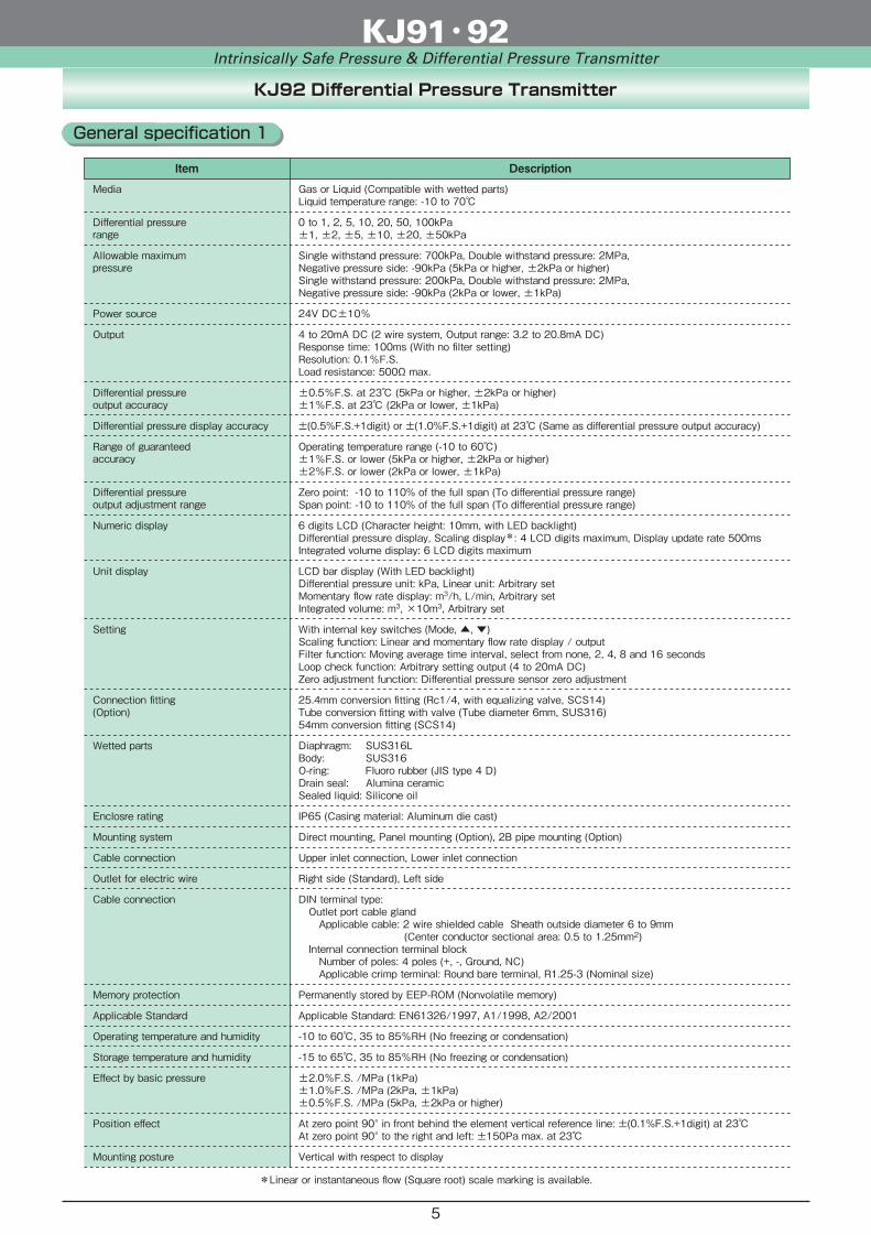
Item Description
Gas or Liquid (Compatible with wetted parts)Liquid temperature range: -10 to 70
0 to 1, 2, 5, 10, 20, 50, 100kPa±1, ±2, ±5, ±10, ±20, ±50kPa
Single withstand pressure: 700kPa, Double withstand pressure: 2MPa,Negative pressure side: -90kPa (5kPa or higher, ±2kPa or higher)Single withstand pressure: 200kPa, Double withstand pressure: 2MPa,Negative pressure side: -90kPa (2kPa or lower, ±1kPa)
24V DC±10%
4 to 20mA DC (2 wire system, Output range: 3.2 to 20.8mA DC)Response time: 100ms (With no filter setting)Resolution: 0.1%F.S. Load resistance: 500Ω max.
±0.5%F.S. at 23 (5kPa or higher, ±2kPa or higher)±1%F.S. at 23 (2kPa or lower, ±1kPa)
Operating temperature range (-10 to 60)±1%F.S. or lower (5kPa or higher, ±2kPa or higher)±2%F.S. or lower (2kPa or lower, ±1kPa)
Zero point: -10 to 110% of the full span (To differential pressure range)Span point: -10 to 110% of the full span (To differential pressure range)
±(0.5%F.S.+1digit) or ±(1.0%F.S.+1digit) at 23 (Same as differential pressure output accuracy)
6 digits LCD (Character height: 10mm, with LED backlight)Differential pressure display, Scaling display*: 4 LCD digits maximum, Display update rate 500msIntegrated volume display: 6 LCD digits maximum
LCD bar display (With LED backlight)Differential pressure unit: kPa, Linear unit: Arbitrary setMomentary flow rate display: m3/h, L/min, Arbitrary setIntegrated volume: m3, ×10m3, Arbitrary set
With internal key switches (Mode, , )Scaling function: Linear and momentary flow rate display / outputFilter function: Moving average time interval, select from none, 2, 4, 8 and 16 secondsLoop check function: Arbitrary setting output (4 to 20mA DC)Zero adjustment function: Differential pressure sensor zero adjustment
25.4mm conversion fitting (Rc1/4, with equalizing valve, SCS14)Tube conversion fitting with valve (Tube diameter 6mm, SUS316)54mm conversion fitting (SCS14)
Diaphragm: SUS316LBody: SUS316O-ring: Fluoro rubber (JIS type 4 D)Drain seal: Alumina ceramicSealed liquid: Silicone oil
IP65 (Casing material: Aluminum die cast)
Direct mounting, Panel mounting (Option), 2B pipe mounting (Option)
Upper inlet connection, Lower inlet connection
Right side (Standard), Left side
DIN terminal type: Outlet port cable gland Applicable cable: 2 wire shielded cable Sheath outside diameter 6 to 9mm (Center conductor sectional area: 0.5 to 1.25mm2) Internal connection terminal block Number of poles: 4 poles (+, -, Ground, NC) Applicable crimp terminal: Round bare terminal, R1.25-3 (Nominal size)
Permanently stored by EEP-ROM (Nonvolatile memory)
Applicable Standard: EN61326/1997, A1/1998, A2/2001
-10 to 60, 35 to 85%RH (No freezing or condensation)
-15 to 65, 35 to 85%RH (No freezing or condensation)
±2.0%F.S. /MPa (1kPa)±1.0%F.S. /MPa (2kPa, ±1kPa)±0.5%F.S. /MPa (5kPa, ±2kPa or higher)
At zero point 90° in front behind the element vertical reference line: ±(0.1%F.S.+1digit) at 23At zero point 90° to the right and left: ±150Pa max. at 23
Vertical with respect to display
KJ92 Differential Pressure Transmitter
*Linear or instantaneous flow (Square root) scale marking is available.
Media
Differential pressurerange
Allowable maximumpressure
Power source
Output
Differential pressureoutput accuracy
Differential pressure display accuracy
Range of guaranteedaccuracy
Differential pressureoutput adjustment range
Numeric display
Unit display
Setting
Connection fitting(Option)
Wetted parts
Enclosre rating
Mounting system
Cable connection
Outlet for electric wire
Cable connection
Memory protection
Applicable Standard
Operating temperature and humidity
Storage temperature and humidity
Effect by basic pressure
Position effect
Mounting posture
KJ91・92Intrinsically Safe Pressure & Differential Pressure Transmitter
General specification 1
5
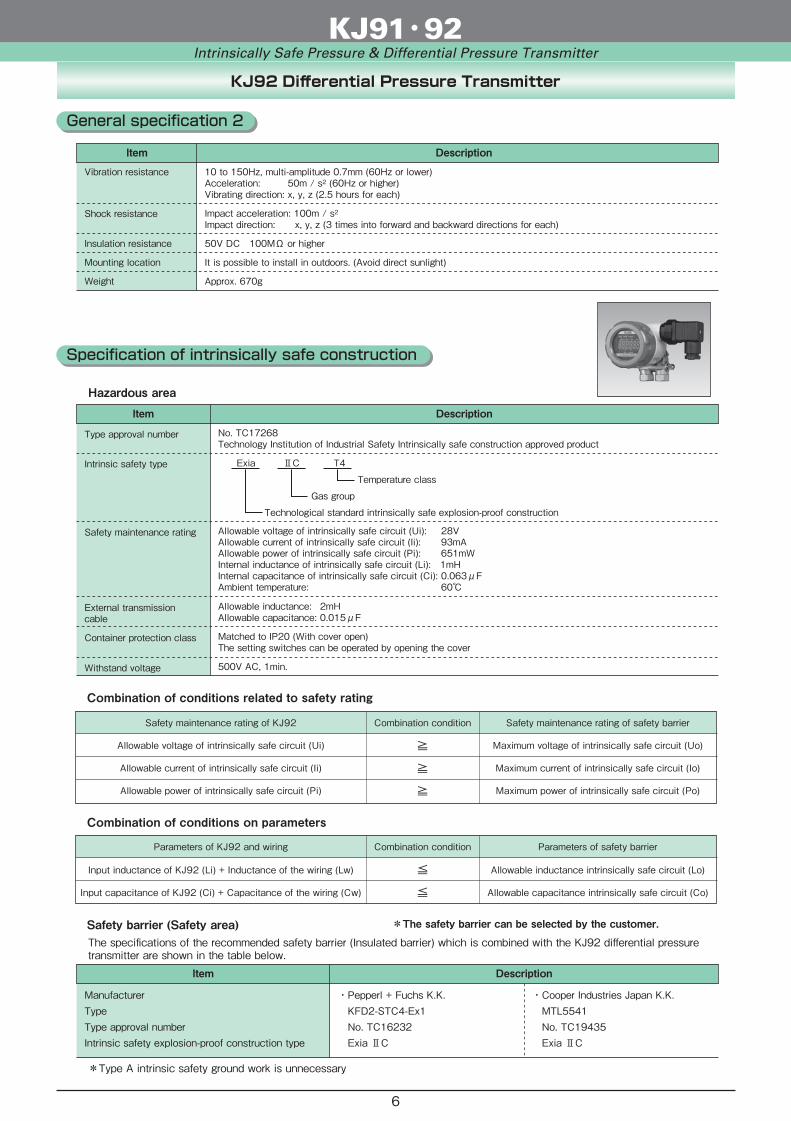
Hazardous area
Specification of intrinsically safe construction
Item Description
No. TC17268Technology Institution of Industrial Safety Intrinsically safe construction approved product
Type approval number
Exia ⅡC T4 Temperature class Gas group Technological standard intrinsically safe explosion-proof construction
Intrinsic safety type
Allowable voltage of intrinsically safe circuit (Ui): 28VAllowable current of intrinsically safe circuit (Ii): 93mAAllowable power of intrinsically safe circuit (Pi): 651mWInternal inductance of intrinsically safe circuit (Li): 1mHInternal capacitance of intrinsically safe circuit (Ci): 0.063μFAmbient temperature: 60
Safety maintenance rating
Allowable inductance: 2mHAllowable capacitance: 0.015μF
External transmission cable
Matched to IP20 (With cover open)The setting switches can be operated by opening the cover
Container protection class
500V AC, 1min.Withstand voltage
Item Description
Approx. 670g
10 to 150Hz, multi-amplitude 0.7mm (60Hz or lower)Acceleration: 50m / s2 (60Hz or higher)Vibrating direction: x, y, z (2.5 hours for each)
Impact acceleration: 100m / s2Impact direction: x, y, z (3 times into forward and backward directions for each)
50V DC 100MΩ or higher
It is possible to install in outdoors. (Avoid direct sunlight)
Safety barrier (Safety area)The specifications of the recommended safety barrier (Insulated barrier) which is combined with the KJ92 differential pressuretransmitter are shown in the table below.
Item Description
*The safety barrier can be selected by the customer.
*Type A intrinsic safety ground work is unnecessary
・Pepperl + Fuchs K.K. KFD2-STC4-Ex1 No. TC16232 Exia ⅡC
・Cooper Industries Japan K.K. MTL5541 No. TC19435 Exia ⅡC
Safety maintenance rating of KJ92 Combination condition Safety maintenance rating of safety barrier
Allowable voltage of intrinsically safe circuit (Ui) ≧
≧
≧
Maximum voltage of intrinsically safe circuit (Uo)
Allowable current of intrinsically safe circuit (Ii) Maximum current of intrinsically safe circuit (Io)
Allowable power of intrinsically safe circuit (Pi) Maximum power of intrinsically safe circuit (Po)
Parameters of KJ92 and wiring Combination condition Parameters of safety barrier
Input inductance of KJ92 (Li) + Inductance of the wiring (Lw) ≦
≦
Allowable inductance intrinsically safe circuit (Lo)
Input capacitance of KJ92 (Ci) + Capacitance of the wiring (Cw) Allowable capacitance intrinsically safe circuit (Co)
Combination of conditions related to safety rating
Combination of conditions on parameters
Vibration resistance
Shock resistance
Insulation resistance
Mounting location
Weight
ManufacturerTypeType approval numberIntrinsic safety explosion-proof construction type
KJ92 Differential Pressure Transmitter
KJ91・92Intrinsically Safe Pressure & Differential Pressure Transmitter
General specification 2
6

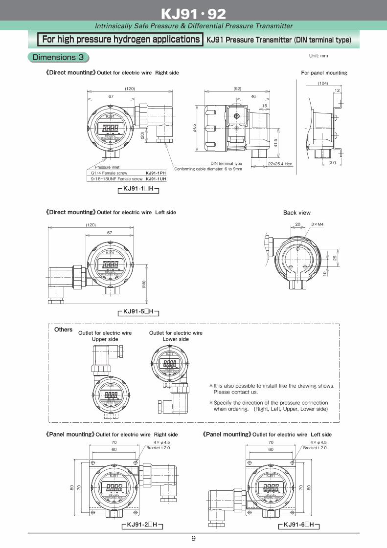
Standard KJ91 Pressure Transmitter (DIN terminal type)
Bracket t 2.0
80 70
60
70 4×φ4.5Bracket t 2.0
8070
60
70 4×φ4.5
Unit: mm
《Direct mounting》Outlet for electric wire Right side For panel mounting
《Direct mounting》Outlet for electric wire Left side
《Panel mounting》Outlet for electric wire Right side
Others
《Panel mounting》Outlet for electric wire Left side
KJ91-1
KJ91-5
KJ91-2 KJ91-6
KJ91-17KJ91-1P
(27)
(104)
12
3×M4
Air inlet port
Air inlet port
46
20
25
10
67
(20)
(120)
φ65
(92)
41.5
φ6
5
φ3
KJ91
kPaMPaNAGANO KEIKI0
KJ91
kPaMPaNAGANO KEIKI0
Detailed drawing of air inlet port(5MPa or lower)
Back view
15
Pressure inletRc1/4G1/4 Female screw Conforming cable diameter: 6 to 9mm
DIN terminal type
22x25.4 Hex.
KJ91
kPaMPaNAGANO KEIKI0
KJ91
kPaMPaNAGANO KEIKI0
*It is also possible to install like the drawing shows. Please contact us. Note) Upper side electrical wire outlet is only available for 10MPa or higher. *Specify the direction of the pressure connection when ordering. (Right, Left, Upper, Lower side)
Outlet for electric wireUpper side
Outlet for electric wireLower side
Air inlet port
(120)
(55)
67
KJ91
kPaMPaNAGANO KEIKI0
KJ91
kPaMPaNAGANO KEIKI0
(5MPa or lower)
(5MPa or lower)
(5MPa or lower)
KJ91・92Intrinsically Safe Pressure & Differential Pressure Transmitter
Dimensions 1
7

《Panel mounting》Outlet for electric wire Right side
KJ91-3
KJ91-4(27)
(104)
12
(92)
φ65
Air inlet port
41.5
Cable length 2m (Standard)
φ6.2, Shielded cable
Plug
Connector
Air inlet port
(125)
67
KJ91
kPaMPaNAGANO KEIKI0
Air inlet port
22x25.4 Hex.
KJ91
kPaMPaNAGANO KEIKI0
Bracket t 2.0
80 70
60
70 4×φ4.5
Connector, cable
With shielded cable (Standard)
Environmentaltemperature Cross-section area
(mm2)
Conductor
Construction(Quantity/mm)
Cable outer diameter(mm)
-20 to 60
-20 to 105
-40 to 80
0.2
0.3
0.3
7/0.18
12/0.18
12/0.18
φ6.2
φ6.2
φ6.0
With heat resistant cable
With cold resistant cable
Connector: TC1108-12A10-7F (Water proof type) (Made by Tajimi Electronics Co., Ltd.)
46
15
φ6
5
φ3
Detailed drawing of vent hole(5MPa or lower)
*Specify the direction of the pressure connection when ordering. (Right, Left, Upper, Lower side)
(5MPa or lower)
(5MPa or lower)
Standard KJ91 Pressure Transmitter (Connector Type)Unit: mm
《Direct mounting》Outlet for electric wire Right side
KJ91・92Intrinsically Safe Pressure & Differential Pressure Transmitter
Dimensions 2
8
Bracket t 2.0
80 70
60
70 4×φ4.5Bracket t 2.0
8070
60
70 4×φ4.5
Unit: mm
《Direct mounting》Outlet for electric wire Right side For panel mounting
《Direct mounting》Outlet for electric wire Left side
《Panel mounting》Outlet for electric wire Right side
Others
《Panel mounting》Outlet for electric wire Left side
KJ91-1H
KJ91-5H
KJ91-2H KJ91-6H
KJ91-1PHKJ91-1UH
(27)
(104)
12
3×M4
46
20
25
10
67
(20)
(120)
φ65
(92)
41.5
KJ91
kPaMPaNAGANO KEIKI0
KJ91
kPaMPaNAGANO KEIKI0
Back view
15
Pressure inletG1/4 Female screw 9/16-18UNF Female screw
Conforming cable diameter: 6 to 9mmDIN terminal type 22x25.4 Hex.
KJ91
kPaMPaNAGANO KEIKI0
KJ91
kPaMPaNAGANO KEIKI0
*It is also possible to install like the drawing shows. Please contact us. *Specify the direction of the pressure connection when ordering. (Right, Left, Upper, Lower side)
Outlet for electric wireUpper side
Outlet for electric wireLower side
(120)
(55)
67
KJ91
kPaMPaNAGANO KEIKI0
KJ91
kPaMPaNAGANO KEIKI0
For high pressure hydrogen applications KJ91 Pressure Transmitter (DIN terminal type)
KJ91・92Intrinsically Safe Pressure & Differential Pressure Transmitter
Dimensions 3
9
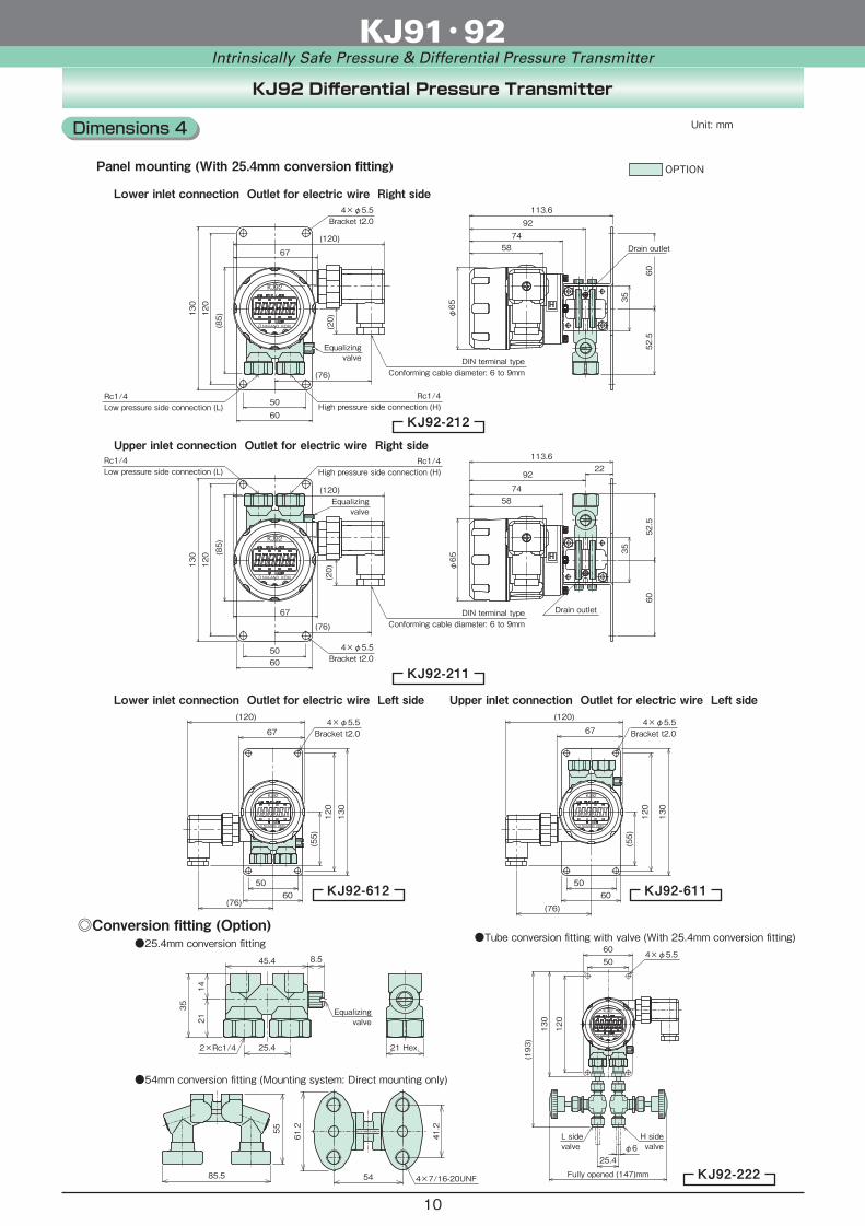
KJ92 Differential Pressure Transmitter
Conversion fitting (Option)Tube conversion fitting with valve (With 25.4mm conversion fitting)
φ6L sidevalve
H sidevalve
Fully opened (147)mm
50
130
25.4
(193)
60
120
4×φ5.5
54mm conversion fitting (Mounting system: Direct mounting only)
4×7/16-20UNF85.5
55
41.2
54
61.2
25.4mm conversion fitting8.545.4
25.4
35
1421
21 Hex.2×Rc1/4
Equalizingvalve
Bracket t2.0(85)
587492
φ65
35
113.6
6052.5
120
130
5060
Drain outlet
4×φ5.5
Panel mounting (With 25.4mm conversion fitting)
Lower inlet connection Outlet for electric wire Right side
Lower inlet connection Outlet for electric wire Left side Upper inlet connection Outlet for electric wire Left side
Equalizingvalve
Rc1/4High pressure side connection (H)
Rc1/4Low pressure side connection (L)
Bracket t2.0
5874
92
φ65
113.6
120
130
5060
4×φ5.552.5
60
22
35
Drain outlet
Upper inlet connection Outlet for electric wire Right side
Equalizingvalve
Rc1/4High pressure side connection (H)
Rc1/4Low pressure side connection (L)
OPTION
(85)
KJ92-212
KJ92-211
KJ92-612 KJ92-611
KJ92-222
67
(20)
(120)
(76)
0 NAGANO KEIKI
KJ92
0 NAGANO KEIKI
KJ92
Conforming cable diameter: 6 to 9mmDIN terminal type
67
(20)
(120)
(76)
0 NAGANO KEIKI
KJ92
Conforming cable diameter: 6 to 9mmDIN terminal type
4×φ5.5Bracket t2.0
(76)60
50
130
120
(55)
67
(120)
KJ92
NAGANO KEIKI0
4×φ5.5Bracket t2.0
(76)60
50
130
120
(55)
67
(120)
KJ92
NAGANO KEIKI0
KJ91・92Intrinsically Safe Pressure & Differential Pressure Transmitter
Unit: mmDimensions 4
10

Function
Panel display
①LCD display The bright and clear LED backlight ensures excellent visibility in a dark place and night time.②Scaling Pressure linearly converted to an arbitrary physical quantity and displayed/output.③Zero adjustment The zero point at 4 to 20mA DC can be adjusted by key operation.④Loop check Without applying pressure, 4 to 20 mA DC can be output arbitrarily. This makes maintenance easy.⑤Filter Pulsations and other pressure changes can be smoothened by moving averages to reduce display fluctuations.⑥Holding display Both the maximum value (Peak) and the minimum value (Bottom) can be indicated.
Unit of pressure
Pressure displayLinear scaling display
ScalingUnit of arbitrary
MODE-key DOWN-key UP-key
KJ91 Pressure Transmitter
Panel display
①LCD display The bright and clear LED backlight ensures excellent visibility in a dark place and night time.②Scaling Differential pressure linearly converted to an arbitrary physical quantity and displayed/output. The square root of the differential pressure is extracted and the instantaneous flow is displayed and output.③Zero adjustment The zero point at 4 to 20mA DC can be adjusted by key operation.④Loop check Without applying pressure, 4 to 20 mA DC can be output arbitrarily. This makes maintenance easy.⑤Filter Pulsations and other differential pressure changes can be smoothened by moving averages to reduce display fluctuations.⑥Integrated volume display The integrated volume is displayed form independently from or alternately with the scaling.
Momentary flow rateStandard unit
Unit of differential pressure
Integrated volumeStandard unit
Scaling display (Linear, Momentary flow rate),Integrated volume display
Differential pressure display,Scaling display (Linear, Momentary flow rate),Integrated volume display
KJ92 Differential Pressure Transmitter
MODE-key DOWN-key UP-key
Integrated volumeIntegrated volume display
CH+ CH-
kPaMPa
M
KJ91
NAGANO KEIKI
CH+ CH-
kPa m3/h L/min
×10m3m3
M
KJ92
NAGANO KEIKI
KJ91・92Intrinsically Safe Pressure & Differential Pressure Transmitter
11

Safety barrier (Insulated barrier)KJ91, 92
Device
1
3
1
2
8
7
14
15
Power supply20 to 35V DC
Receivergauge
KFD2-STC4-Ex1
+
+
++
-
-
-
Safety barrier (Insulated barrier)
2
1
12
11
14
13
MTL5541
+
+
+
-
-
--E
Safety areaHazardous area
+
-
+
-
3
2
1
Shield cable
Terminal blockPlug
Gasket
Terminal block Socket
ScrewBody (KJ91)
Cable gland
Wiring of DIN type terminal
1 Power source +
2 Power source -
3 N.C.
Earth (E)
KJ91・92Intrinsically Safe Pressure & Differential Pressure Transmitter
・Classification of applicable to hazardous area (Whole range) ・Ignition point of gas or steam which T4 can apply (Within bold-line rectangle)
Applicable temperature class
Higher than 450
Higher than 300
Higher than 200
Higher than 135
Higher than 100
Higher than 85
Ignition point of gas or steam
T1 T2 T3 T4 T5 T6
T2 T3 T4 T5 T6
T3 T4 T5 T6
T4 T5 T6
T5 T6
T6
Hazardous area Contents
Zone 0A place where hazardous atmosphere iscontinuously present or present for a longperiod under ordinary circumstances.
A place where hazardous atmosphere islikely to occur under ordinary circumstances.
A place where hazardous atmosphere islikely to occur under abnormal circumstances.
Zone 1
Zone 2
Reference data
・Example of gas or steam which can apply Exia ⅡC T4 (Within bold-line rectangle)
T1
ⅡA
ⅡB
ⅡC
T2 T3 T4 T5 T6Group
Temperatureclass
Acetone
Ammonia
Carbon monoxide
Ethane
Propane
Methanol
Methane
Ethanol
1-butanol
Butane
Ethylene
Ethylene oxide
Hexane
Gasoline
Oil naphtha
Coal tar naphtha
DME
Hydrogen
Water gas
Coal gas
Acetylene
Acetaldehyde
Ethyl ether
Ethyl methyl
Ether
Carbon bisulfide Nitric acid ethyl
Wiring
12

K J 9 1 1 11 0 0①Pressure Transmitter
(DIN terminal type)② ③ ④ ⑤ ⑥ ⑦ ⑧ ⑨ ⑩ ⑪ ⑫ ⑬ ⑭ ⑮
Product specificationsModel number Additional specifications (Optional)
*1 Standard is "Outlet for electric wire: right, Pressure Connection: lower"
*2 Please contact us for the 9/16-18UNF requirement.
*3 Conversion joint will be attached.
・Please contact us for high corrosion resistant material.
Standard KJ91 Pressure Transmitter (DIN terminal type)
KJ91・92Intrinsically Safe Pressure & Differential Pressure Transmitter
Model
Please specify the model number, each specs and the range for ordering.Model number configuration
1RightOutlet for electric wire
Mounting Pressure Connection
Direct mounting
Mounting system①
2 Panel mountingA Direct mountingB Direct mountingC
5Left
6GHJ Direct mounting
LowerLowerRightUpperLeft
7 Rc1/4 (Standard)Connectionfitting*2
②3 G3/8 (With Rc1/4+FJ12-373, option)*3
4 G1/2 (With Rc1/4+FJ12-473, option)*3
9 Rc1/2 (With Rc1/4+FJ10-973, option)*3
P G1/4 Female screw (Option)36
Diaphragm: SUS630 (17-4PH) Fitting: SUS316Wetted parts③
Diaphragm: Co-Ni alloy (High corrosion resistant use) Fitting: SUS316
1Outlet for electricwire
⑧
0 Not requiredTreatment⑪
1 Use no oil2 Use no water3 Use no oil & water
Required (Documents available upon request) Datasheet (Drawing / Specifications) Instruction manual Calibration test report (One-part one sheet) Inspection / Traceability certificate
0 Not requiredDocuments⑮
1
DIN terminal type(Conforming electric wire diameter: 6 to 9mm)
0Cable type⑨ Not required
1Output⑦ 4 to 20mA DC (2 wire system)
1Supply voltage⑥ 24V DC ±10%
*1
50MPa or lowercan be selected
2 -0.1 to 0.2MPa
Pressure range(MPa)
④
3 -0.1 to 0.3MPa5 -0.1 to 0.5MPa
C 0 to 0.3MPaE 0 to 0.5MPaG 0 to 1MPa
Pressure range Maximumdisplay value
0.2001 -0.1 to 0.1MPa 0.100
0.3000.500
6 -0.1 to 1.0MPa 1.0000.3000.5001.000
J 0 to 2MPaK 0 to 3.5MPaL 0 to 5MPaN 0 to 10MPa
2.0003.505.0010.00
Q 0 to 20MPaR 0 to 35MPa
20.0035.0
STUV
0 to 50MPa 50.0
Available accuracy±0.25%F.S. at 23 ±0.5%F.S. at 23
-------
0 to 70MPa 70.00 to 100MPa 100.00 to 120MPa 120.04
Accuracy⑤ ±0.25%F.S. at 23
5 ±0.5%F.S. at 23
0 Not requiredAdditional spec.⑩
1 Diaphragm seal type(Please consult us)
0 Standard spec.Application⑫
*Specify code "X" to refer N/A
Please specify pressurerange and unit of measurealong with correspondingordering code.
Order separately for recommended safety barrier.If using a barrier other than recommended barrier,strictly observe the "Safety Maintenance Rating".
Treatment against wetted partsUse no oil Oil used in manufacturing the gauges had been flushed out & no oil residue remained inside its wetted parts. Use no water Water used in manufacturing the gauges had been flushed out & no water residue remained inside its wetted parts. Use no oil & water Oil/Water used in manufacturing the gauges had been flushed out & no oil/water residue remained inside its wetted parts.
13
*1 Standard is "Outlet for electric wire: right, Pressure Connection: lower"
*2 Please contact us for the 9/16-18UNF requirement.
*3 Conversion joint will be attached.
・Please contact us for high corrosion resistant material.
*Specify code "X" to refer N/A
Order separately for recommended safety barrier.If using a barrier other than recommended barrier,strictly observe the "Safety Maintenance Rating".
Treatment against wetted partsUse no oil Oil used in manufacturing the gauges had been flushed out & no oil residue remained inside its wetted parts. Use no water Water used in manufacturing the gauges had been flushed out & no water residue remained inside its wetted parts. Use no oil & water Oil/Water used in manufacturing the gauges had been flushed out & no oil/water residue remained inside its wetted parts.
K J 9 1 1 0 01①Pressure Transmitter
(Connector Type)② ③ ④ ⑤ ⑥ ⑦ ⑧ ⑨ ⑩ ⑪ ⑫ ⑬ ⑭ ⑮
Product specificationsModel number Additional specifications (Optional)
50MPa or lowercan be selected
Standard KJ91 Pressure Transmitter (Connector Type)
KJ91・92Intrinsically Safe Pressure & Differential Pressure Transmitter
Model
Please specify the model number, each specs and the range for ordering.Model number configuration
3RightOutlet for electric wire
Mounting Pressure Connection
Direct mounting
Mounting system①
4 Panel mountingD Direct mountingE Direct mountingF
7Left
8KLM Direct mounting
LowerLowerRightUpperLeft
7 Rc1/4 (Standard)Connectionfitting*2
②3 G3/8 (With Rc1/4+FJ12-373, option)*3
4 G1/2 (With Rc1/4+FJ12-473, option)*3
9 Rc1/2 (With Rc1/4+FJ10-973, option)*3
P G1/4 Female screw (Option)36
Diaphragm: SUS630 (17-4PH) Fitting: SUS316Wetted parts③
Diaphragm: Co-Ni alloy (High corrosion resistant use) Fitting: SUS316
0Outlet for electricwire
⑧
0 Not requiredTreatment⑪
1 Use no oil2 Use no water3 Use no oil & water
Not required
1Cable type⑨ With shielded cable 2m (Standard)
1Output⑦ 4 to 20mA DC (2 wire system)
1Supply voltage⑥ 24V DC ±10%
*1
2 -0.1 to 0.2MPa
Pressure range(MPa)
Please specify pressurerange and unit of measurealong with correspondingordering code.
④
3 -0.1 to 0.3MPa5 -0.1 to 0.5MPa
C 0 to 0.3MPaE 0 to 0.5MPaG 0 to 1MPa
Pressure range Maximumdisplay value
0.2001 -0.1 to 0.1MPa 0.100
0.3000.500
6 -0.1 to 1.0MPa 1.0000.3000.5001.000
J 0 to 2MPaK 0 to 3.5MPaL 0 to 5MPaN 0 to 10MPa
2.0003.505.0010.00
Q 0 to 20MPaR 0 to 35MPa
20.0035.0
STUV
0 to 50MPa 50.0
Available accuracy±0.25%F.S. at 23 ±0.5%F.S. at 23
-------
0 to 70MPa 70.00 to 100MPa 100.00 to 120MPa 120.04
Accuracy⑤ ±0.25%F.S. at 23
5 ±0.5%F.S. at 23
2 With heat resistant cable3 With cold resistant cable
0 Not requiredAdditional spec.⑩
1 Diaphragm seal type(Please consult us)
0 Standard spec.Application⑫
0 Not requiredDocuments⑮
1 Required (Documents available upon request) Datasheet (Drawing / Specifications) Instruction manual Calibration test report (One-part one sheet) Inspection / Traceability certificate
14

K J 9 1 1 11H 0 0 3①Pressure Transmitter
(DIN terminal type)② ③ ④ ⑤ ⑥ ⑦ ⑧ ⑨ ⑩ ⑪ ⑫ ⑬ ⑭ ⑮
Product specificationsModel number Additional specifications (Optional)
1RightOutlet for electric wire Mounting Pressure Connection
Direct mounting
Mounting system①
2 Panel mountingA Direct mountingB Direct mountingC
5Left
6GHJ Direct mounting
LowerLowerRightUpperLeft
P G1/4 Female screwConnection fitting②
U 9/16-18UNF Female screw F250C or equivalent by Autoclave
H Diaphragm: SUH660 (A286)Fitting: SUS316LWetted parts
③
1Outlet for electricwire
⑧
3 Use no oil & waterTreatment⑪
Required (Documents available upon request) Datasheet (Drawing / Specifications) Instruction manual Calibration test report (One-part one sheet) Inspection / Traceability certificate
0 Not requiredDocuments⑮
1
DIN terminal type(Conforming electric wire diameter: 6 to 9mm)
0Cable type⑨ Not required
1Output⑦ 4 to 20mA DC (2 wire system)
1Supply voltage⑥ 24V DC ±10%
*1 Standard is "Outlet for electric wire: right, Pressure Connection: lower"
*1
Pressure range(MPa)
④ Pressure rangePlease specify pressurerange and unit of measurealong with correspondingordering code.
Maximumdisplay value
R 0 to 35MPa 35.0STUV
0 to 50MPa 50.0
Available accuracy±0.25%F.S. at 23 ±0.5%F.S. at 23
---
0 to 70MPa 70.0 0 to 100MPa 100.0 0 to 120MPa 120.04
Accuracy⑤ ±0.25%F.S. at 23
5 ±0.5%F.S. at 23
0 Not requiredAdditional spec.⑩
7 【Standard】Air tightness test report (Helium leak test)Application
⑫
A Proof pressure, leak test report(Additional document)
*Specify code "X" to refer N/A
Order separately for recommended safety barrier.If using a barrier other than recommended barrier,strictly observe the "Safety Maintenance Rating".
Treatment against wetted partsUse no oil Oil used in manufacturing the gauges had been flushed out & no oil residue remained inside its wetted parts. Use no water Water used in manufacturing the gauges had been flushed out & no water residue remained inside its wetted parts. Use no oil & water Oil/Water used in manufacturing the gauges had been flushed out & no oil/water residue remained inside its wetted parts.
Model
Please specify the model number, each specs and the range for ordering.Model number configuration
KJ91・92Intrinsically Safe Pressure & Differential Pressure Transmitter
For high pressure hydrogen applications KJ91 Pressure Transmitter (DIN terminal type)
15

K J 9 2 1 1 1①Differential Pressure Transmitter ② ③ ④ ⑤ ⑥ ⑦ ⑧ ⑨ ⑩ ⑪ ⑫ ⑬ ⑭ ⑮
Product specificationsModel number Additional specifications (Optional)
1RightOutlet for electric wire
Direct mounting
Mounting system①
2 Panel mounting3
5Left
67 2B pipe mounting
0 Not requiredConversion fitting②
1 25.4mm conversion fitting (Rc1/4)(With equalizing valve, option)2 Tube conversion fitting with valve (Option)3 54mm conversion fitting (Option) Only direct mounting can be selected
1 Upper inlet connectionPressureConnection
③2 Lower inlet connection
R 0 to 1kPaDifferentialpressure range
④
S 0 to 2kPaT 0 to 5kPaU 0 to 10kPaV 0 to 20kPaW 0 to 50kPaX 0 to 100kPaF ± 1kPa
RangePlease specify differentialpressure range and unitof measure along withcorresponding ordering code.
Max. display value
G ± 2kPaH ± 5kPaJ ±10kPaK ±20kPaL ±50kPa
1.0002.005.0010.0020.050.0100.0±1.00±2.00±5.00±10.0±20.0±50.0
Accuracy (Standard)
±1.0%F.S. at 23
±0.5%F.S. at 23
±1.0%F.S. at 23
±0.5%F.S. at 23
5Accuracy⑤ ±0.5%F.S. at 23 (5kPa or higher, ±2kPa or higher)
7 ±1.0%F.S. at 23 (2kPa or lower, ±1kPa)
1Outlet for electricwire
⑧ DIN terminal type(Conforming electric wire diameter: 6 to 9mm)
1Output
Treatment against wetted partsUse no oil Oil used in manufacturing the gauges had been flushed out & no oil residue remained inside its wetted parts. Use no water Water used in manufacturing the gauges had been flushed out & no water residue remained inside its wetted parts. Use no oil & water Oil/Water used in manufacturing the gauges had been flushed out & no oil/water residue remained inside its wetted parts.
⑦ 4 to 20mA DC (2 wire system)
1Supply voltage⑥ 24V DC ±10%
*Specify code "X" to refer N/A
0 Not requiredTreatment⑩
1 Use no oil2 Use no water3 Use no oil & water0 Not required
Documents⑮
1 Required (Documents available upon request) Datasheet (Drawing / Specifications) Instruction manual Calibration test report (One-part one sheet) Inspection / Traceability certificate
Mounting*
* Specify a pressure Connection by ③
Order separately for recommended safety barrier.If using a barrier other than recommended barrier,strictly observe the "Safety Maintenance Rating".
KJ92 Differential Pressure Transmitter
KJ91・92Intrinsically Safe Pressure & Differential Pressure Transmitter
Model
Please specify the model, each requiring specification and differential pressure range to order.Model number configuration
16

Introduction of related products
GC51 Pressure Transmitter
GC51Pressure Transmitter(Explosion proof type KJ91)
NV80 Pitot Tube Type Digital Flow meter
GC52 Differential Pressure Transmitter
NV81/82/83 Orifice Type Digital Flow meter
Non-intrinsically safe type
Pressure range
Flow meter
GC52Differential Pressure Transmitter(Explosion proof type KJ92)
0 to 1kPa→ 0 to 100kPa-1 to 1kPa→ -50 to 50kPa
0 to 0.3MPa→ 0 to 120MPa-0.1 to 0.1MPa→ -0.1 to 1MPa
-0.1 0 0.1 1 10 100
(MPa)
120
-0.1 1
Gauge pressure
Compound
-100 -10 -1 0 1 10 100
100
-50 50 (kPa)
Differential pressure
Differential pressure(± Range)
KJ91・92Intrinsically Safe Pressure & Differential Pressure Transmitter
17