catalogue glass - nabertherm - glass, arts and crafts ... · pdf file glass furnaces and heat...
TRANSCRIPT
www.nabertherm.com
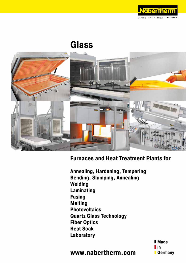
Glass
Furnaces and Heat Treatment Plants for
Annealing, Hardening, TemperingBending, Slumping, AnnealingWeldingLaminatingFusingMeltingPhotovoltaicsQuartz Glass TechnologyFiber OpticsHeat SoakLaboratory
MadeinGermany
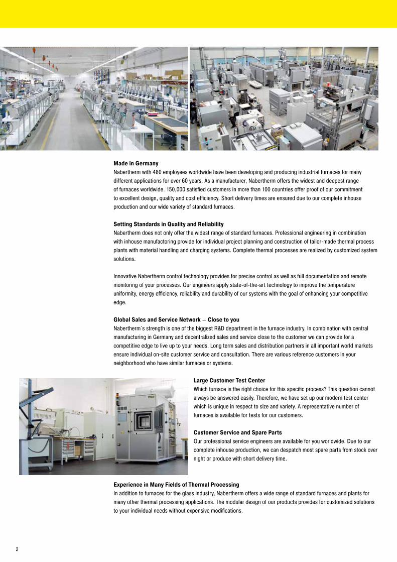
Made in GermanyNabertherm with 480 employees worldwide have been developing and producing industrial furnaces for many different applications for over 60 years. As a manufacturer, Nabertherm offers the widest and deepest range of furnaces worldwide. 150,000 satisfied customers in more than 100 countries offer proof of our commitment to excellent design, quality and cost efficiency. Short delivery times are ensured due to our complete inhouse production and our wide variety of standard furnaces.
Setting Standards in Quality and ReliabilityNabertherm does not only offer the widest range of standard furnaces. Professional engineering in combination with inhouse manufactoring provide for individual project planning and construction of tailor-made thermal process plants with material handling and charging systems. Complete thermal processes are realized by customized system solutions.
Innovative Nabertherm control technology provides for precise control as well as full documentation and remote monitoring of your processes. Our engineers apply state-of-the-art technology to improve the temperature uniformity, energy efficiency, reliability and durability of our systems with the goal of enhancing your competitive edge.
Global Sales and Service Network – Close to youNabertherm´s strength is one of the biggest R&D department in the furnace industry. In combination with central manufacturing in Germany and decentralized sales and service close to the customer we can provide for a competitive edge to live up to your needs. Long term sales and distribution partners in all important world markets ensure individual on-site customer service and consultation. There are various reference customers in your neighborhood who have similar furnaces or systems.
Large Customer Test CenterWhich furnace is the right choice for this specific process? This question cannot always be answered easily. Therefore, we have set up our modern test center which is unique in respect to size and variety. A representative number of furnaces is available for tests for our customers.
Customer Service and Spare PartsOur professional service engineers are available for you worldwide. Due to our complete inhouse production, we can despatch most spare parts from stock over night or produce with short delivery time.
Experience in Many Fields of Thermal ProcessingIn addition to furnaces for the glass industry, Nabertherm offers a wide range of standard furnaces and plants formany other thermal processing applications. The modular design of our products provides for customized solutionsto your individual needs without expensive modifications.
2
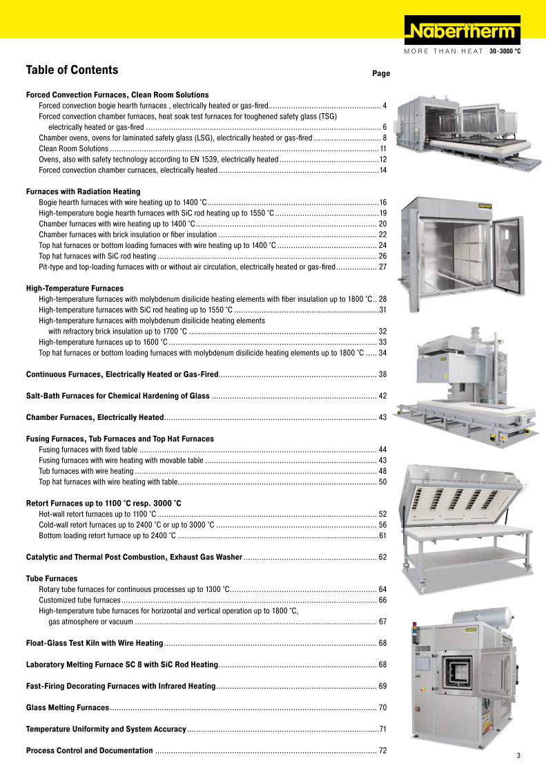
Table of Contents Page
Forced Convection Furnaces, Clean Room SolutionsForced convection bogie hearth furnaces , electrically heated or gas-fired.................................................. 4Forced convection chamber furnaces, heat soak test furnaces for toughened safety glass (TSG) electrically heated or gas-fired ........................................................................................................ 6Chamber ovens, ovens for laminated safety glass (LSG), electrically heated or gas-fired .............................. 8Clean Room Solutions .......................................................................................................................11Ovens, also with safety technology according to EN 1539, electrically heated ............................................12Forced convection chamber curnaces, electrically heated .......................................................................14
Furnaces with Radiation HeatingBogie hearth furnaces with wire heating up to 1400 °C ............................................................................16High-temperature bogie hearth furnaces with SiC rod heating up to 1550 °C ..............................................19Chamber furnaces with wire heating up to 1400 °C ................................................................................ 20Chamber furnaces with brick insulation or fiber insulation ...................................................................... 22Top hat furnaces or bottom loading furnaces with wire heating up to 1400 °C ............................................ 24Top hat furnaces with SiC rod heating ................................................................................................. 26Pit-type and top-loading furnaces with or without air circulation, electrically heated or gas-fired .................. 27
High-Temperature FurnacesHigh-temperature furnaces with molybdenum disilicide heating elements with fiber insulation up to 1800 °C .. 28High-temperature furnaces with SiC rod heating up to 1550 °C ................................................................31High-temperature furnaces with molybdenum disilicide heating elements with refractory brick insulation up to 1700 °C ................................................................................... 32High-temperature furnaces up to 1600 °C ............................................................................................ 33Top hat furnaces or bottom loading furnaces with molybdenum disilicide heating elements up to 1800 °C ..... 34
Continuous Furnaces, Electrically Heated or Gas-Fired...................................................................... 38
Salt-Bath Furnaces for Chemical Hardening of Glass ......................................................................... 42
Chamber Furnaces, Electrically Heated .............................................................................................. 43
Fusing Furnaces, Tub Furnaces and Top Hat FurnacesFusing furnaces with fixed table ......................................................................................................... 44Fusing furnaces with wire heating with movable table ............................................................................ 43Tub furnaces with wire heating ........................................................................................................... 48Top hat furnaces with wire heating with table ........................................................................................ 50
Retort Furnaces up to 1100 °C resp. 3000 °CHot-wall retort furnaces up to 1100 °C ................................................................................................. 52Cold-wall retort furnaces up to 2400 °C or up to 3000 °C ....................................................................... 56Bottom loading retort furnace up to 2400 °C .........................................................................................61
Catalytic and Thermal Post Combustion, Exhaust Gas Washer ........................................................... 62
Tube FurnacesRotary tube furnaces for continuous processes up to 1300 °C ................................................................. 64Customized tube furnaces ................................................................................................................. 66High-temperature tube furnaces for horizontal and vertical operation up to 1800 °C, gas atmosphere or vacuum ........................................................................................................... 67
Float-Glass Test Kiln with Wire Heating .............................................................................................. 68
Laboratory Melting Furnace SC 8 with SiC Rod Heating ...................................................................... 68
Fast-Firing Decorating Furnaces with Infrared Heating ....................................................................... 69
Glass Melting Furnaces ...................................................................................................................... 70
Temperature Uniformity and System Accuracy .....................................................................................71
Process Control and Documentation .................................................................................................. 723
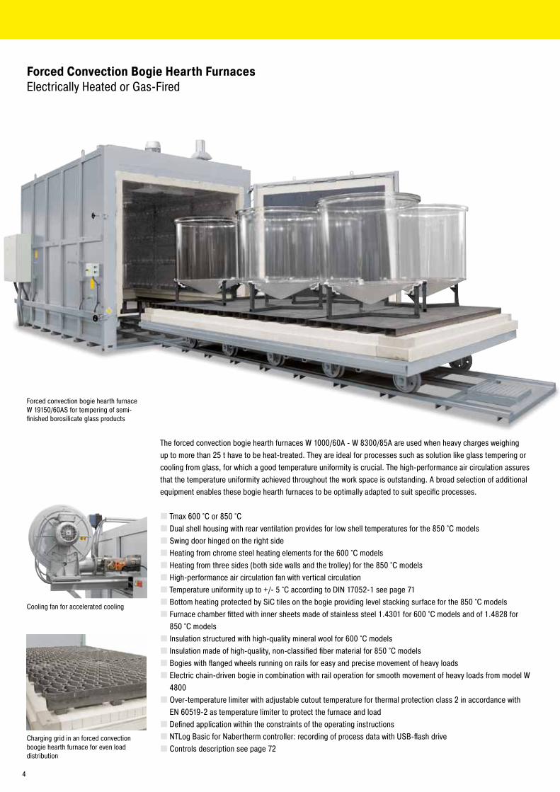
Forced convection bogie hearth furnace W 19150/60AS for tempering of semi-finished borosilicate glass products
Forced Convection Bogie Hearth Furnaces Electrically Heated or Gas-Fired
The forced convection bogie hearth furnaces W 1000/60A - W 8300/85A are used when heavy charges weighing up to more than 25 t have to be heat-treated. They are ideal for processes such as solution like glass tempering or cooling from glass, for which a good temperature uniformity is crucial. The high-performance air circulation assures that the temperature uniformity achieved throughout the work space is outstanding. A broad selection of additional equipment enables these bogie hearth furnaces to be optimally adapted to suit specific processes.
� Tmax 600 °C or 850 °C � Dual shell housing with rear ventilation provides for low shell temperatures for the 850 °C models � Swing door hinged on the right side � Heating from chrome steel heating elements for the 600 °C models � Heating from three sides (both side walls and the trolley) for the 850 °C models � High-performance air circulation fan with vertical circulation � Temperature uniformity up to +/- 5 °C according to DIN 17052-1 see page 71 � Bottom heating protected by SiC tiles on the bogie providing level stacking surface for the 850 °C models � Furnace chamber fitted with inner sheets made of stainless steel 1.4301 for 600 °C models and of 1.4828 for 850 °C models � Insulation structured with high-quality mineral wool for 600 °C models � Insulation made of high-quality, non-classified fiber material for 850 °C models � Bogies with flanged wheels running on rails for easy and precise movement of heavy loads � Electric chain-driven bogie in combination with rail operation for smooth movement of heavy loads from model W 4800 � Over-temperature limiter with adjustable cutout temperature for thermal protection class 2 in accordance with EN 60519-2 as temperature limiter to protect the furnace and load � Defined application within the constraints of the operating instructions � NTLog Basic for Nabertherm controller: recording of process data with USB-flash drive � Controls description see page 72
Cooling fan for accelerated cooling
Charging grid in an forced convection boogie hearth furnace for even load distribution
4

Forced convection bogie hearth furnace W 3300/85S with chain drive
Additional equipment � Direct gas heating or upon request with indirect gas heating with radiation tube � Electric chain-driven bogie in combination with rail operation for smooth movement of heavy loads up to Model W 4000 � Optimization of the temperature uniformity up +/- 3 °C according to DIN 17052-1 see page 71 � Bogie running on steel wheels with gear rack drive, no rails in front of the furnace necessary � Different possibilities for an extension to a bogie hearth furnace plant:
- Additional bogies - Bogie transfer system with parking rails to exchange bogies running on rails or to connect multiples furnaces - Motor-driven bogies and cross-traversal system - Fully automatic control of the bogie exchange
� Electro-hydraulic lift door � Motor-driven exhaust air flaps, adjustable via the program � Uncontrolled or controlled cooling system with frequency-controlled cooling fan and motor-driven exhaust air flap � Multi-zone control adapted to the particular furnace model provides for optimum temperature uniformity in the 850 °C models � Commissioning of the furnace with test firing and temperature uniformity measurement (also with load) for the purpose of process optimization � Designed for Tmax 950 °C, fan blade driven indirectly via a belt to protect the air recirculation motor against over-heating � Process control and documentation via VCD software package or Nabertherm Control Center (NCC) for monitoring, documentation and control see page 72
Model Tmax Inner dimensions in mm Volume Outer dimensions in mm Heating power Electrical°C w d h in l W D H in kW1 connection*
W 1000/.. A 800 1600 800 1000 1800 2390 2305 45 3-phaseW 1600/.. A 1000 1600 1000 1600 2000 2390 2535 45 3-phaseW 2200/.. A 1000 2250 1000 2200 2000 3040 2535 90 3-phaseW 3300/.. A 600 1200 2250 1200 3300 2200 3040 2745 90 3-phaseW 4000/.. A or 1500 2250 1200 4000 2500 3040 2780 110 3-phaseW 4800/.. A 850 1200 3300 1200 4800 2200 4090 2780 110 3-phaseW 6000/.. A 1500 3300 1200 6000 2500 4090 2900 140 3-phaseW 6600/.. A 1200 4600 1200 6600 2200 5390 2770 140 3-phaseW 7500/.. A 1400 3850 1400 7500 2400 4640 2980 140 3-phaseW 8300/.. A 1500 4600 1200 8300 2500 5390 2780 185 3-phase
1Depending on furnace design connected load might be higher *Please see page 73 for more information about supply voltage
Forced convection bogie hearth furnace W 10430/85AS
5
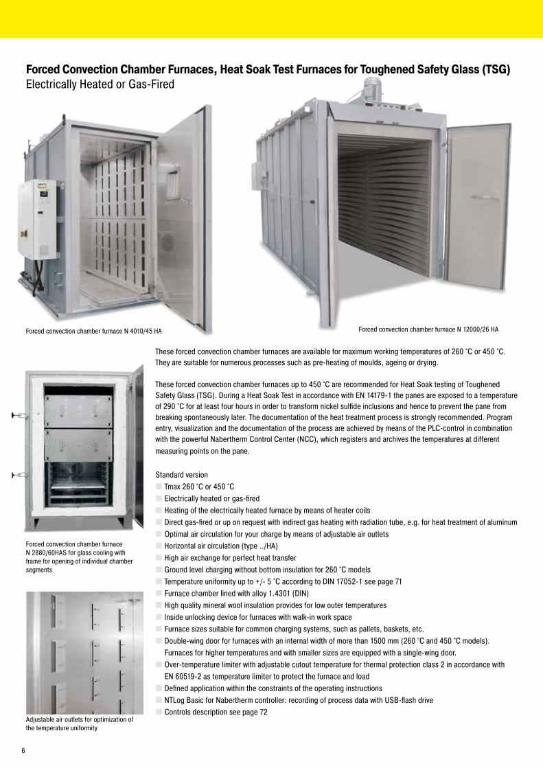
Forced Convection Chamber Furnaces, Heat Soak Test Furnaces for Toughened Safety Glass (TSG) Electrically Heated or Gas-Fired
Forced convection chamber furnace N 2880/60HAS for glass cooling with frame for opening of individual chamber segments
Adjustable air outlets for optimization of the temperature uniformity
These forced convection chamber furnaces are available for maximum working temperatures of 260 °C or 450 °C. They are suitable for numerous processes such as pre-heating of moulds, ageing or drying.
These forced convection chamber furnaces up to 450 °C are recommended for Heat Soak testing of Toughened Safety Glass (TSG). During a Heat Soak Test in accordance with EN 14179-1 the panes are exposed to a temperature of 290 °C for at least four hours in order to transform nickel sulfide inclusions and hence to prevent the pane from breaking spontaneously later. The documentation of the heat treatment process is strongly recommended. Program entry, visualization and the documentation of the process are achieved by means of the PLC-control in combination with the powerful Nabertherm Control Center (NCC), which registers and archives the temperatures at different measuring points on the pane.
Standard version � Tmax 260 °C or 450 °C � Electrically heated or gas-fired � Heating of the electrically heated furnace by means of heater coils � Direct gas-fired or up on request with indirect gas heating with radiation tube, e.g. for heat treatment of aluminum � Optimal air circulation for your charge by means of adjustable air outlets � Horizontal air circulation (type ../HA) � High air exchange for perfect heat transfer � Ground level charging without bottom insulation for 260 °C models � Temperature uniformity up to +/- 5 °C according to DIN 17052-1 see page 71 � Furnace chamber lined with alloy 1.4301 (DIN) � High quality mineral wool insulation provides for low outer temperatures � Inside unlocking device for furnaces with walk-in work space � Furnace sizes suitable for common charging systems, such as pallets, baskets, etc. � Double-wing door for furnaces with an internal width of more than 1500 mm (260 °C and 450 °C models). Furnaces for higher temperatures and with smaller sizes are equipped with a single-wing door. � Over-temperature limiter with adjustable cutout temperature for thermal protection class 2 in accordance with EN 60519-2 as temperature limiter to protect the furnace and load � Defined application within the constraints of the operating instructions � NTLog Basic for Nabertherm controller: recording of process data with USB-flash drive � Controls description see page 72
Forced convection chamber furnace N 4010/45 HA Forced convection chamber furnace N 12000/26 HA
6
Temperature recording in accordance with EN 14179-1
Loading rack for glass panes
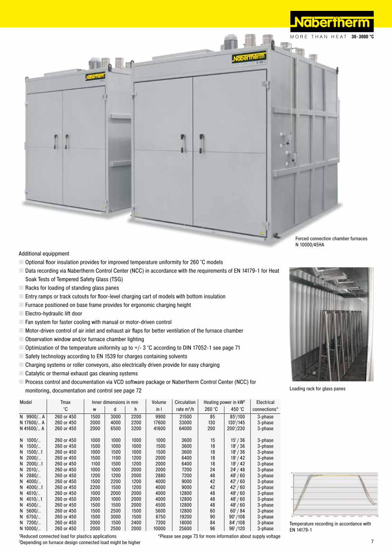
Model Tmax Inner dimensions in mm Volume Circulation Heating power in kW2 Electrical°C w d h in l rate m3/h 260 °C 450 °C connections*
N 9900/.. A 260 or 450 1500 3000 2200 9900 21500 85 851/100 3-phaseN 17600/.. A 260 or 450 2000 4000 2200 17600 33000 130 1301/145 3-phaseN 41600/.. A 260 or 450 2000 6500 3200 41600 64000 200 2001/230 3-phase
N 1000/.. 260 or 450 1000 1000 1000 1000 3600 15 151 / 36 3-phaseN 1500/.. 260 or 450 1500 1000 1000 1500 3600 18 181 / 36 3-phaseN 1500/..1 260 or 450 1000 1500 1000 1500 3600 18 181 / 36 3-phaseN 2000/.. 260 or 450 1500 1100 1200 2000 6400 18 181 / 42 3-phaseN 2000/..1 260 or 450 1100 1500 1200 2000 6400 18 181 / 42 3-phaseN 2010/.. 260 or 450 1000 1000 2000 2000 7200 24 241 / 48 3-phaseN 2880/.. 260 or 450 1200 1200 2000 2880 7200 48 481 / 60 3-phaseN 4000/.. 260 or 450 1500 2200 1200 4000 9000 42 421 / 60 3-phaseN 4000/..1 260 or 450 2200 1500 1200 4000 9000 42 421 / 60 3-phaseN 4010/.. 260 or 450 1000 2000 2000 4000 12800 48 481 / 60 3-phaseN 4010/..1 260 or 450 2000 1000 2000 4000 12800 48 481 / 60 3-phaseN 4500/.. 260 or 450 1500 1500 2000 4500 12800 48 481 / 60 3-phaseN 5600/.. 260 or 450 1500 2500 1500 5600 12800 60 601 / 84 3-phaseN 6750/.. 260 or 450 1500 3000 1500 6750 19200 90 901 /108 3-phaseN 7200/.. 260 or 450 2000 1500 2400 7200 18000 84 841 /108 3-phaseN 10000/.. 260 or 450 2000 2500 2000 10000 25600 96 961 /120 3-phase
1Reduced connected load for plastics applications *Please see page 73 for more information about supply voltage2Depending on furnace design connected load might be higher
Additional equippment � Optional floor insulation provides for improved temperature uniformity for 260 °C models � Data recording via Nabertherm Control Center (NCC) in accordance with the requirements of EN 14179-1 for Heat Soak Tests of Tempered Safety Glass (TSG) � Racks for loading of standing glass panes � Entry ramps or track cutouts for floor-level charging cart of models with bottom insulation � Furnace positioned on base frame provides for ergonomic charging height � Electro-hydraulic lift door � Fan system for faster cooling with manual or motor-driven control � Motor-driven control of air inlet and exhaust air flaps for better ventilation of the furnace chamber � Observation window and/or furnace chamber lighting � Optimization of the temperature uniformity up to +/- 3 °C according to DIN 17052-1 see page 71 � Safety technology according to EN 1539 for charges containing solvents � Charging systems or roller conveyors, also electrically driven provide for easy charging � Catalytic or thermal exhaust gas cleaning systems � Process control and documentation via VCD software package or Nabertherm Control Center (NCC) for monitoring, documentation and control see page 72
Forced convection chamber furnaces N 10000/45HA
7
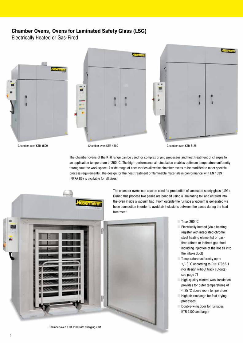
Chamber Ovens, Ovens for Laminated Safety Glass (LSG) Electrically Heated or Gas-Fired
The chamber ovens of the KTR range can be used for complex drying processes and heat treatment of charges to an application temperature of 260 °C. The high-performance air circulation enables optimum temperature uniformity throughout the work space. A wide range of accessories allow the chamber ovens to be modified to meet specific process requirements. The design for the heat treatment of flammable materials in conformance with EN 1539 (NFPA 86) is available for all sizes.
Chamber oven KTR 1500 with charging cart
The chamber ovens can also be used for production of laminated safety glass (LSG). During this process two panes are bonded using a laminating foil and entered into the oven inside a vacuum bag. From outside the furnace a vacuum is generated via hose connection in order to avoid air inclusions between the panes during the heat treatment.
� Tmax 260 °C � Electrically heated (via a heating register with integrated chrome steel heating elements) or gas-fired (direct or indirect gas-fired including injection of the hot air into the intake duct) � Temperature uniformity up to +/- 3 °C according to DIN 17052-1 (for design wihout track cutouts) see page 71 � High-quality mineral wool insulation provides for outer temperatures of < 25 °C above room temperature � High air exchange for fast drying processes � Double-wing door for furnaces KTR 3100 and larger
Chamber oven KTR 1500 Chamber oven KTR 4500 Chamber oven KTR 6125
8
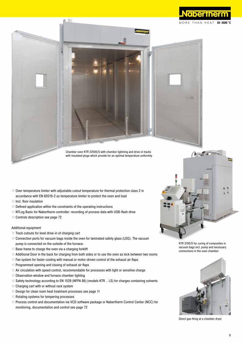
KTR 3100/S for curing of composites in vacuum bags incl. pump and necessary connections in the oven chamber
� Over-temperature limiter with adjustable cutout temperature for thermal protection class 2 in accordance with EN 60519-2 as temperature limiter to protect the oven and load � Incl. floor insulation � Defined application within the constraints of the operating instructions � NTLog Basic for Nabertherm controller: recording of process data with USB-flash drive � Controls description see page 72
Additional equipment � Track cutouts for level drive-in of charging cart � Connection ports for vacuum bags inside the oven for laminated safety glass (LSG). The vacuum pump is connected on the outside of the furnace. � Base frame to charge the oven via a charging forklift � Additional Door in the back for charging from both sides or to use the oven as lock between two rooms � Fan system for faster cooling with manual or motor-driven control of the exhaust air flaps � Programmed opening and closing of exhaust air flaps � Air circulation with speed control, recommendable for processes with light or sensitive charge � Observation window and furnace chamber lighting � Safety technology according to EN 1539 (NFPA 86) (models KTR .. LS) for charges containing solvents � Charging cart with or without rack system � Design for clean room heat treatment processes see page 11 � Rotating systems for tempering processes � Process control and documentation via VCD software package or Nabertherm Control Center (NCC) for monitoring, documentation and control see page 72
Chamber oven KTR 22500/S with chamber lightning and drive-in tracks with insulated plugs which provide for an optimal temperature uniformity
Direct gas-firing at a chamber dryer
9
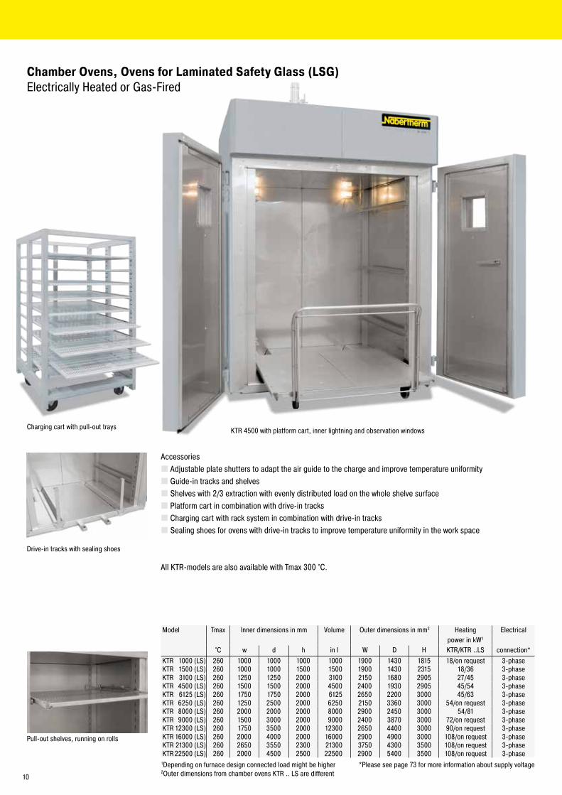
Charging cart with pull-out trays
Model Tmax Inner dimensions in mm Volume Outer dimensions in mm2 Heating Electricalpower in kW1
°C w d h in l W D H KTR/KTR ..LS connection*KTR 1000 (LS) 260 1000 1000 1000 1000 1900 1430 1815 18/on request 3-phaseKTR 1500 (LS) 260 1000 1000 1500 1500 1900 1430 2315 18/36 3-phaseKTR 3100 (LS) 260 1250 1250 2000 3100 2150 1680 2905 27/45 3-phaseKTR 4500 (LS) 260 1500 1500 2000 4500 2400 1930 2905 45/54 3-phaseKTR 6125 (LS) 260 1750 1750 2000 6125 2650 2200 3000 45/63 3-phaseKTR 6250 (LS) 260 1250 2500 2000 6250 2150 3360 3000 54/on request 3-phaseKTR 8000 (LS) 260 2000 2000 2000 8000 2900 2450 3000 54/81 3-phaseKTR 9000 (LS) 260 1500 3000 2000 9000 2400 3870 3000 72/on request 3-phaseKTR 12300 (LS) 260 1750 3500 2000 12300 2650 4400 3000 90/on request 3-phaseKTR 16000 (LS) 260 2000 4000 2000 16000 2900 4900 3000 108/on request 3-phaseKTR 21300 (LS) 260 2650 3550 2300 21300 3750 4300 3500 108/on request 3-phaseKTR 22500 (LS) 260 2000 4500 2500 22500 2900 5400 3500 108/on request 3-phase
1Depending on furnace design connected load might be higher *Please see page 73 for more information about supply voltage2Outer dimensions from chamber ovens KTR .. LS are different
KTR 4500 with platform cart, inner lightning and observation windows
Accessories � Adjustable plate shutters to adapt the air guide to the charge and improve temperature uniformity � Guide-in tracks and shelves � Shelves with 2/3 extraction with evenly distributed load on the whole shelve surface � Platform cart in combination with drive-in tracks � Charging cart with rack system in combination with drive-in tracks � Sealing shoes for ovens with drive-in tracks to improve temperature uniformity in the work space
All KTR-models are also available with Tmax 300 °C.
Pull-out shelves, running on rolls
Drive-in tracks with sealing shoes
Chamber Ovens, Ovens for Laminated Safety Glass (LSG) Electrically Heated or Gas-Fired
10
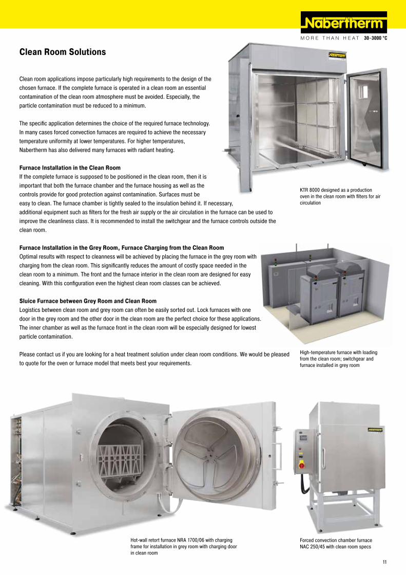
Clean room applications impose particularly high requirements to the design of the chosen furnace. If the complete furnace is operated in a clean room an essential contamination of the clean room atmosphere must be avoided. Especially, the particle contamination must be reduced to a minimum.
The specific application determines the choice of the required furnace technology. In many cases forced convection furnaces are required to achieve the necessary temperature uniformity at lower temperatures. For higher temperatures, Nabertherm has also delivered many furnaces with radiant heating.
Furnace Installation in the Clean RoomIf the complete furnace is supposed to be positioned in the clean room, then it is important that both the furnace chamber and the furnace housing as well as the controls provide for good protection against contamination. Surfaces must be easy to clean. The furnace chamber is tightly sealed to the insulation behind it. If necessary, additional equipment such as filters for the fresh air supply or the air circulation in the furnace can be used to improve the cleanliness class. It is recommended to install the switchgear and the furnace controls outside the clean room.
Furnace Installation in the Grey Room, Furnace Charging from the Clean RoomOptimal results with respect to cleanness will be achieved by placing the furnace in the grey room with charging from the clean room. This significantly reduces the amount of costly space needed in the clean room to a minimum. The front and the furnace interior in the clean room are designed for easy cleaning. With this configuration even the highest clean room classes can be achieved.
Sluice Furnace between Grey Room and Clean RoomLogistics between clean room and grey room can often be easily sorted out. Lock furnaces with one door in the grey room and the other door in the clean room are the perfect choice for these applications. The inner chamber as well as the furnace front in the clean room will be especially designed for lowest particle contamination.
Please contact us if you are looking for a heat treatment solution under clean room conditions. We would be pleased to quote for the oven or furnace model that meets best your requirements.
Clean Room Solutions
High-temperature furnace with loading from the clean room; switchgear and furnace installed in grey room
KTR 8000 designed as a production oven in the clean room with filters for air circulation
Hot-wall retort furnace NRA 1700/06 with charging frame for installation in grey room with charging door in clean room
Forced convection chamber furnace NAC 250/45 with clean room specs
11
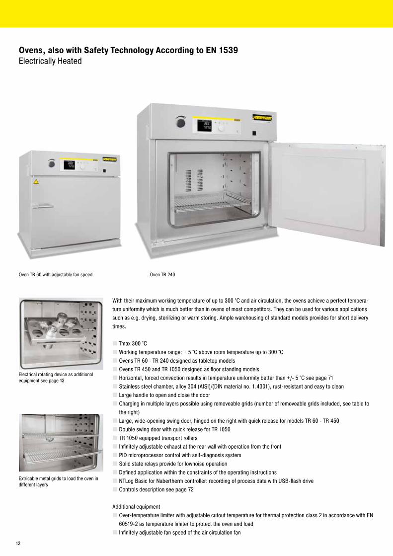
Ovens, also with Safety Technology According to EN 1539 Electrically Heated
With their maximum working temperature of up to 300 °C and air circulation, the ovens achieve a perfect tempera-ture uniformity which is much better than in ovens of most competitors. They can be used for various applications such as e.g. drying, sterilizing or warm storing. Ample warehousing of standard models provides for short delivery times.
� Tmax 300 °C �Working temperature range: + 5 °C above room temperature up to 300 °C � Ovens TR 60 - TR 240 designed as tabletop models � Ovens TR 450 and TR 1050 designed as floor standing models � Horizontal, forced convection results in temperature uniformity better than +/- 5 °C see page 71 � Stainless steel chamber, alloy 304 (AISI)/(DIN material no. 1.4301), rust-resistant and easy to clean � Large handle to open and close the door � Charging in multiple layers possible using removeable grids (number of removeable grids included, see table to the right) � Large, wide-opening swing door, hinged on the right with quick release for models TR 60 - TR 450 � Double swing door with quick release for TR 1050 � TR 1050 equipped transport rollers � Infinitely adjustable exhaust at the rear wall with operation from the front � PID microprocessor control with self-diagnosis system � Solid state relays provide for low noise operation � Defined application within the constraints of the operating instructions � NTLog Basic for Nabertherm controller: recording of process data with USB-flash drive � Controls description see page 72
Additional equipment � Over-temperature limiter with adjustable cutout temperature for thermal protection class 2 in accordance with EN 60519-2 as temperature limiter to protect the oven and load � Infinitely adjustable fan speed of the air circulation fan
Extricable metal grids to load the oven in different layers
Electrical rotating device as additional equipment see page 13
Oven TR 60 with adjustable fan speed Oven TR 240
12
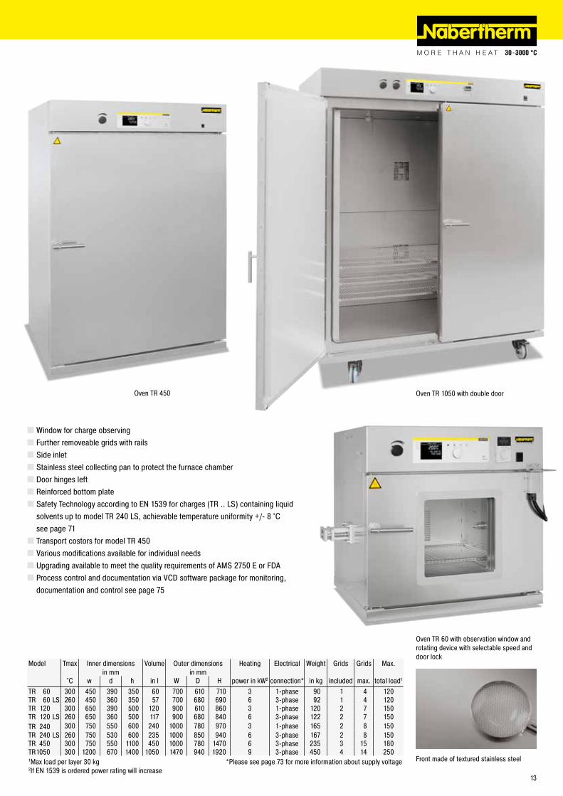
Oven TR 1050 with double door
�Window for charge observing � Further removeable grids with rails � Side inlet � Stainless steel collecting pan to protect the furnace chamber � Door hinges left � Reinforced bottom plate � Safety Technology according to EN 1539 for charges (TR .. LS) containing liquid solvents up to model TR 240 LS, achievable temperature uniformity +/- 8 °C see page 71 � Transport costors for model TR 450 � Various modifications available for individual needs � Upgrading available to meet the quality requirements of AMS 2750 E or FDA � Process control and documentation via VCD software package for monitoring, documentation and control see page 75
Model Tmax Inner dimensions in mm
Volume Outer dimensions in mm
Heating Electrical Weight Grids Grids Max.
°C w d h in l W D H power in kW2 connection* in kg included max. total load1
TR 60 300 450 390 350 60 700 610 710 3 1-phase 90 1 4 120TR 60 LS 260 450 360 350 57 700 680 690 6 3-phase 92 1 4 120TR 120 300 650 390 500 120 900 610 860 3 1-phase 120 2 7 150TR 120 LS 260 650 360 500 117 900 680 840 6 3-phase 122 2 7 150TR 240 300 750 550 600 240 1000 780 970 3 1-phase 165 2 8 150TR 240 LS 260 750 530 600 235 1000 850 940 6 3-phase 167 2 8 150TR 450 300 750 550 1100 450 1000 780 1470 6 3-phase 235 3 15 180TR 1050 300 1200 670 1400 1050 1470 940 1920 9 3-phase 450 4 14 2501Max load per layer 30 kg *Please see page 73 for more information about supply voltage2If EN 1539 is ordered power rating will increase
Oven TR 60 with observation window and rotating device with selectable speed and door lock
Front made of textured stainless steel
Oven TR 450
13
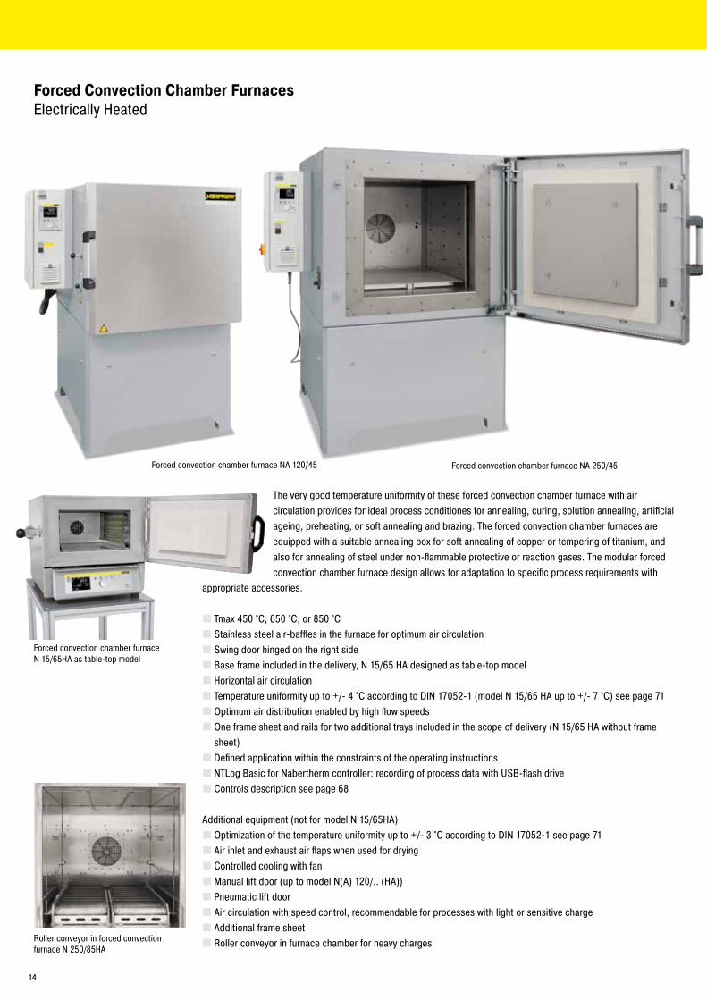
Forced Convection Chamber Furnaces Electrically Heated
The very good temperature uniformity of these forced convection chamber furnace with air circulation provides for ideal process conditiones for annealing, curing, solution annealing, artificial ageing, preheating, or soft annealing and brazing. The forced convection chamber furnaces are equipped with a suitable annealing box for soft annealing of copper or tempering of titanium, and also for annealing of steel under non-flammable protective or reaction gases. The modular forced convection chamber furnace design allows for adaptation to specific process requirements with
appropriate accessories.
� Tmax 450 °C, 650 °C, or 850 °C � Stainless steel air-baffles in the furnace for optimum air circulation � Swing door hinged on the right side � Base frame included in the delivery, N 15/65 HA designed as table-top model � Horizontal air circulation � Temperature uniformity up to +/- 4 °C according to DIN 17052-1 (model N 15/65 HA up to +/- 7 °C) see page 71 � Optimum air distribution enabled by high flow speeds � One frame sheet and rails for two additional trays included in the scope of delivery (N 15/65 HA without frame sheet) � Defined application within the constraints of the operating instructions � NTLog Basic for Nabertherm controller: recording of process data with USB-flash drive � Controls description see page 68
Additional equipment (not for model N 15/65HA) � Optimization of the temperature uniformity up to +/- 3 °C according to DIN 17052-1 see page 71 � Air inlet and exhaust air flaps when used for drying � Controlled cooling with fan � Manual lift door (up to model N(A) 120/.. (HA)) � Pneumatic lift door � Air circulation with speed control, recommendable for processes with light or sensitive charge � Additional frame sheet � Roller conveyor in furnace chamber for heavy charges
Forced convection chamber furnace N 15/65HA as table-top model
Roller conveyor in forced convection furnace N 250/85HA
Forced convection chamber furnace NA 120/45 Forced convection chamber furnace NA 250/45
14
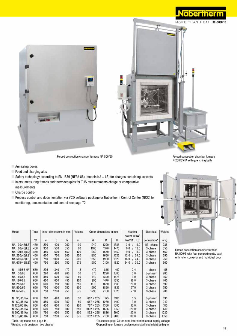
Model Tmax Inner dimensions in mm Volume Outer dimensions in mm Heating Electrical Weightpower in kW3
°C w d h in l W D H NA/NA .. LS connection* in kgNA 30/45(LS) 450 290 420 260 30 1040 1290 1385 3.0 / 9.0 1(3)-phase 285NA 60/45(LS) 450 350 500 350 60 1100 1370 1475 6.0 / 12.0 3-phase 350NA 120/45(LS) 450 450 600 450 120 1250 1550 1550 9.0 / 18.0 3-phase 460NA 250/45(LS) 450 600 750 600 250 1350 1650 1725 12.0 / 24.0 3-phase 590NA 500/45(LS) 450 750 1000 750 500 1550 1900 1820 18.0 / 24.0 3-phase 750NA 675/45(LS) 450 750 1200 750 675 1550 2100 1820 24.0 / 30.0 3-phase 900
N 15/65 HA1 650 295 340 170 15 470 845 460 2.4 1-phase 55NA 30/65 650 290 420 260 30 870 1290 1385 5.0 3-phase2 285N A 60/65 650 350 500 350 60 910 1390 1475 9.0 3-phase 350NA 120/65 650 450 600 450 120 990 1470 1550 12.0 3-phase 460NA 250/65 650 600 750 600 250 1170 1650 1680 20.0 3-phase 590NA 500/65 650 750 1000 750 500 1290 1890 1825 27.0 3-phase 750NA 675/65 650 750 1200 750 675 1290 2100 1825 27.0 3-phase 900
N 30/85 HA 850 290 420 260 30 607 + 255 1175 1315 5.5 3-phase2 195N 60/85 HA 850 350 500 350 60 667 + 255 1250 1400 9.0 3-phase 240N 120/85 HA 850 450 600 450 120 767 + 255 1350 1500 13.0 3-phase 310N 250/85 HA 850 600 750 600 250 1002 + 255 1636 1860 20.0 3-phase 610N 500/85 HA 850 750 1000 750 500 1152 + 255 1886 2010 30.0 3-phase 1030N 675/85 HA 850 750 1200 750 675 1152 + 255 2100 2010 30.0 3-phase 1350
1Table-top model see page 14 *Please see page 73 for more information about supply voltage2Heating only beetween two phases 3Depending on furnace design connected load might be higher
� Annealing boxes � Feed and charging aids � Safety technology according to EN 1539 (NFPA 86) (models NA .. LS) for charges containing solvents � Inlets, measuring frames and thermocouples for TUS measurements charge or comparative measurements � Charge control � Process control and documentation via VCD software package or Nabertherm Control Center (NCC) for monitoring, documentation and control see page 72
Forced convection chamber furnace N 250/85HA with quenching bath
Forced convection chamber furnace NA 500/65
Forced convection chamber furnace NA 500/S with four compartments, each with roller conveyor and individual door
15
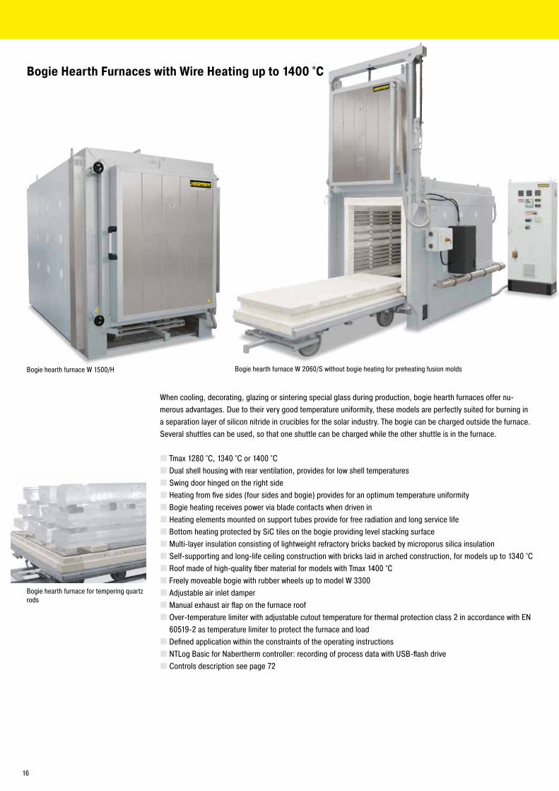
Bogie hearth furnace for tempering quartz rods
Bogie Hearth Furnaces with Wire Heating up to 1400 °C
Bogie hearth furnace W 2060/S without bogie heating for preheating fusion molds
When cooling, decorating, glazing or sintering special glass during production, bogie hearth furnaces offer nu-merous advantages. Due to their very good temperature uniformity, these models are perfectly suited for burning in a separation layer of silicon nitride in crucibles for the solar industry. The bogie can be charged outside the furnace. Several shuttles can be used, so that one shuttle can be charged while the other shuttle is in the furnace.
� Tmax 1280 °C, 1340 °C or 1400 °C � Dual shell housing with rear ventilation, provides for low shell temperatures � Swing door hinged on the right side � Heating from five sides (four sides and bogie) provides for an optimum temperature uniformity � Bogie heating receives power via blade contacts when driven in � Heating elements mounted on support tubes provide for free radiation and long service life � Bottom heating protected by SiC tiles on the bogie providing level stacking surface � Multi-layer insulation consisting of lightweight refractory bricks backed by microporus silica insulation � Self-supporting and long-life ceiling construction with bricks laid in arched construction, for models up to 1340 °C � Roof made of high-quality fiber material for models with Tmax 1400 °C � Freely moveable bogie with rubber wheels up to model W 3300 � Adjustable air inlet damper � Manual exhaust air flap on the furnace roof � Over-temperature limiter with adjustable cutout temperature for thermal protection class 2 in accordance with EN 60519-2 as temperature limiter to protect the furnace and load � Defined application within the constraints of the operating instructions � NTLog Basic for Nabertherm controller: recording of process data with USB-flash drive � Controls description see page 72
Bogie hearth furnace W 1500/H
16
Bogie hearth furnace W 8250/S for tempe-ring quartz glass
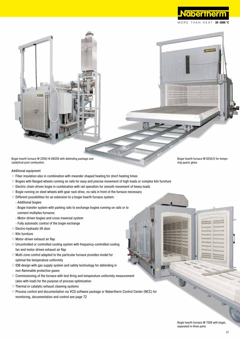
Additional equipment � Fiber insulation also in combination with meander shaped heating for short heating times � Bogies with flanged wheels running on rails for easy and precise movement of high loads or complex kiln furniture � Electric chain-driven bogie in combination with rail operation for smooth movement of heavy loads � Bogie running on steel wheels with gear rack drive, no rails in front of the furnace necessary � Different possibilities for an extension to a bogie hearth furnace system:
- Additional bogies - Bogie transfer system with parking rails to exchange bogies running on rails or to connect multiples furnaces - Motor-driven bogies and cross-traversal system - Fully automatic control of the bogie exchange
� Electro-hydraulic lift door � Kiln furniture � Motor-driven exhaust air flap � Uncontrolled or controlled cooling system with frequency-controlled cooling fan and motor-driven exhaust air flap � Multi-zone control adapted to the particular furnace provides model for optimal the temperature uniformity � IDB design with gas supply system and safety technology for debinding in non-flammable protective gases � Commissioning of the furnace with test firing and temperature uniformity measurement (also with load) for the purpose of process optimization � Thermal or catalytic exhaust cleaning systems � Process control and documentation via VCD software package or Nabertherm Control Center (NCC) for monitoring, documentation and control see page 72
Bogie hearth furnace W 2200/14 DB200 with debinding package and catalytical post combustion
Bogie hearth furnace W 7500 with bogie, separated in three parts
17
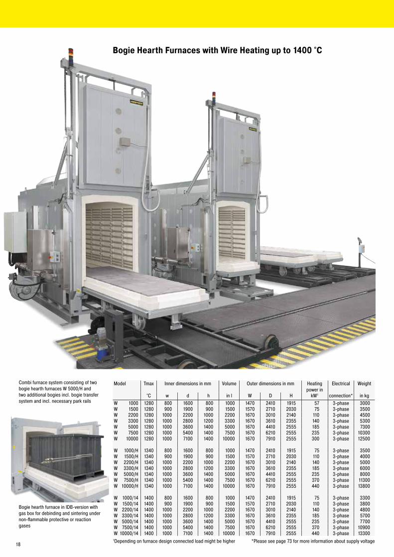
Bogie Hearth Furnaces with Wire Heating up to 1400 °C
Combi furnace system consisting of two bogie hearth furnaces W 5000/H and two additional bogies incl. bogie transfer system and incl. necessary park rails
Bogie hearth furnace in IDB-version with gas box for debinding and sintering under non-flammable protective or reaction gases
Model Tmax Inner dimensions in mm Volume Outer dimensions in mm Heatingpower in
Electrical Weight
°C w d h in l W D H kW1 connection* in kgW 1000 1280 800 1600 800 1000 1470 2410 1915 57 3-phase 3000W 1500 1280 900 1900 900 1500 1570 2710 2030 75 3-phase 3500W 2200 1280 1000 2200 1000 2200 1670 3010 2140 110 3-phase 4500W 3300 1280 1000 2800 1200 3300 1670 3610 2355 140 3-phase 5300W 5000 1280 1000 3600 1400 5000 1670 4410 2555 185 3-phase 7300W 7500 1280 1000 5400 1400 7500 1670 6210 2555 235 3-phase 10300W 10000 1280 1000 7100 1400 10000 1670 7910 2555 300 3-phase 12500
W 1000/H 1340 800 1600 800 1000 1470 2410 1915 75 3-phase 3500W 1500/H 1340 900 1900 900 1500 1570 2710 2030 110 3-phase 4000W 2200/H 1340 1000 2200 1000 2200 1670 3010 2140 140 3-phase 5000W 3300/H 1340 1000 2800 1200 3300 1670 3610 2355 185 3-phase 6000W 5000/H 1340 1000 3600 1400 5000 1670 4410 2555 235 3-phase 8000W 7500/H 1340 1000 5400 1400 7500 1670 6210 2555 370 3-phase 11300W 10000/H 1340 1000 7100 1400 10000 1670 7910 2555 440 3-phase 13800
W 1000/14 1400 800 1600 800 1000 1470 2410 1915 75 3-phase 3300W 1500/14 1400 900 1900 900 1500 1570 2710 2030 110 3-phase 3800W 2200/14 1400 1000 2200 1000 2200 1670 3010 2140 140 3-phase 4800W 3300/14 1400 1000 2800 1200 3300 1670 3610 2355 185 3-phase 5700W 5000/14 1400 1000 3600 1400 5000 1670 4410 2555 235 3-phase 7700W 7500/14 1400 1000 5400 1400 7500 1670 6210 2555 370 3-phase 10900W 10000/14 1400 1000 7100 1400 10000 1670 7910 2555 440 3-phase 13300
1Depending on furnace design connected load might be higher *Please see page 73 for more information about supply voltage18
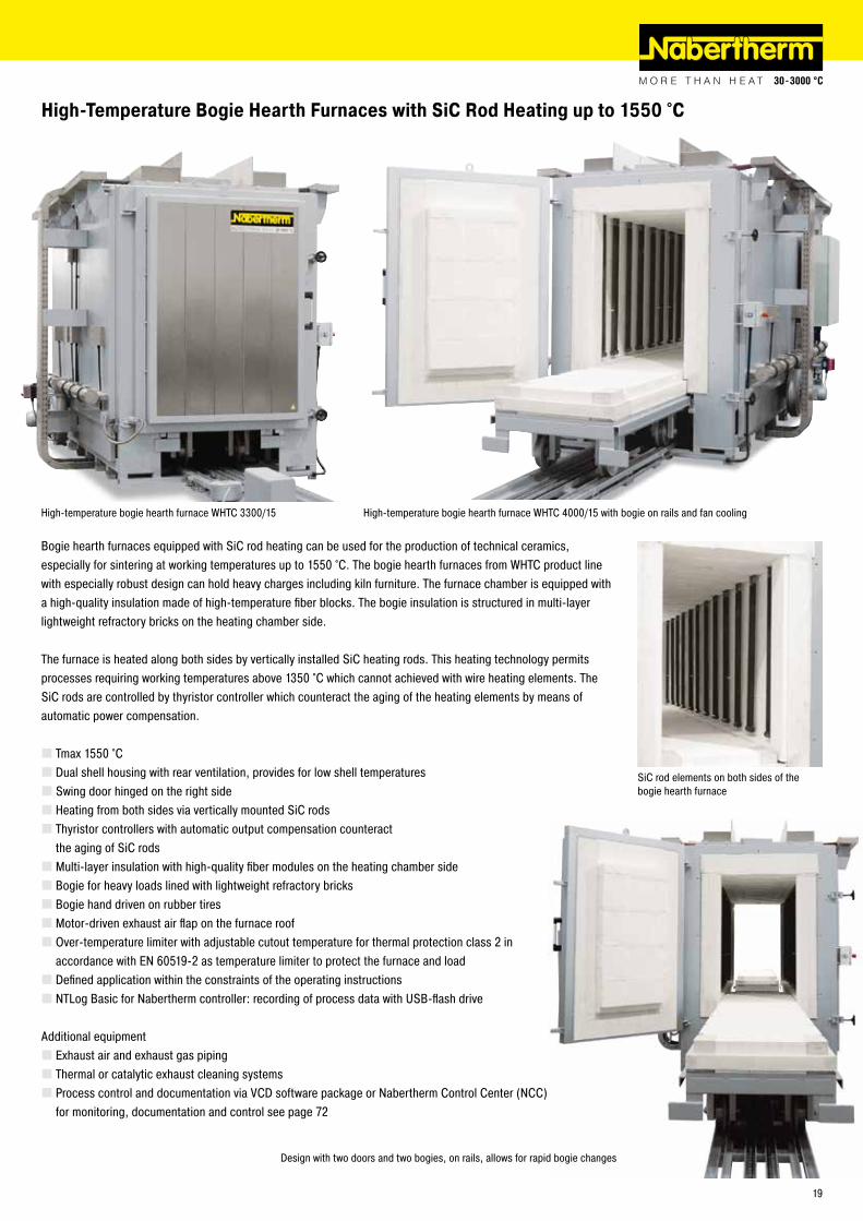
Bogie hearth furnaces equipped with SiC rod heating can be used for the production of technical ceramics, especially for sintering at working temperatures up to 1550 °C. The bogie hearth furnaces from WHTC product line with especially robust design can hold heavy charges including kiln furniture. The furnace chamber is equipped with a high-quality insulation made of high-temperature fiber blocks. The bogie insulation is structured in multi-layer lightweight refractory bricks on the heating chamber side.
The furnace is heated along both sides by vertically installed SiC heating rods. This heating technology permits processes requiring working temperatures above 1350 °C which cannot achieved with wire heating elements. The SiC rods are controlled by thyristor controller which counteract the aging of the heating elements by means of automatic power compensation.
� Tmax 1550 °C � Dual shell housing with rear ventilation, provides for low shell temperatures � Swing door hinged on the right side � Heating from both sides via vertically mounted SiC rods � Thyristor controllers with automatic output compensation counteract the aging of SiC rods � Multi-layer insulation with high-quality fiber modules on the heating chamber side � Bogie for heavy loads lined with lightweight refractory bricks � Bogie hand driven on rubber tires � Motor-driven exhaust air flap on the furnace roof � Over-temperature limiter with adjustable cutout temperature for thermal protection class 2 in accordance with EN 60519-2 as temperature limiter to protect the furnace and load � Defined application within the constraints of the operating instructions � NTLog Basic for Nabertherm controller: recording of process data with USB-flash drive
Additional equipment � Exhaust air and exhaust gas piping � Thermal or catalytic exhaust cleaning systems � Process control and documentation via VCD software package or Nabertherm Control Center (NCC) for monitoring, documentation and control see page 72
High-temperature bogie hearth furnace WHTC 4000/15 with bogie on rails and fan cooling
SiC rod elements on both sides of the bogie hearth furnace
Design with two doors and two bogies, on rails, allows for rapid bogie changes
High-Temperature Bogie Hearth Furnaces with SiC Rod Heating up to 1550 °C
High-temperature bogie hearth furnace WHTC 3300/15
19
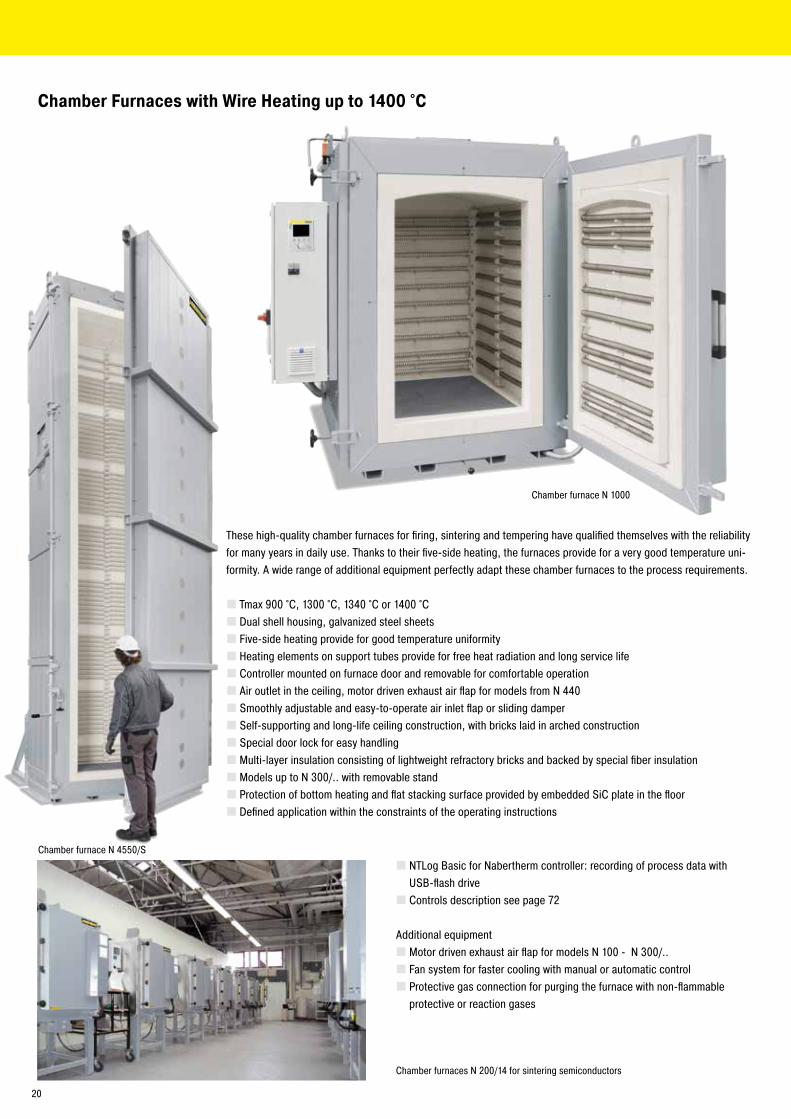
Chamber Furnaces with Wire Heating up to 1400 °C
These high-quality chamber furnaces for firing, sintering and tempering have qualified themselves with the reliability for many years in daily use. Thanks to their five-side heating, the furnaces provide for a very good temperature uni-formity. A wide range of additional equipment perfectly adapt these chamber furnaces to the process requirements.
� Tmax 900 °C, 1300 °C, 1340 °C or 1400 °C � Dual shell housing, galvanized steel sheets � Five-side heating provide for good temperature uniformity � Heating elements on support tubes provide for free heat radiation and long service life � Controller mounted on furnace door and removable for comfortable operation � Air outlet in the ceiling, motor driven exhaust air flap for models from N 440 � Smoothly adjustable and easy-to-operate air inlet flap or sliding damper � Self-supporting and long-life ceiling construction, with bricks laid in arched construction � Special door lock for easy handling � Multi-layer insulation consisting of lightweight refractory bricks and backed by special fiber insulation � Models up to N 300/.. with removable stand � Protection of bottom heating and flat stacking surface provided by embedded SiC plate in the floor � Defined application within the constraints of the operating instructions
� NTLog Basic for Nabertherm controller: recording of process data with USB-flash drive � Controls description see page 72
Additional equipment � Motor driven exhaust air flap for models N 100 - N 300/.. � Fan system for faster cooling with manual or automatic control � Protective gas connection for purging the furnace with non-flammable protective or reaction gases
Chamber furnaces N 200/14 for sintering semiconductors
Chamber furnace N 1000
Chamber furnace N 4550/S
20
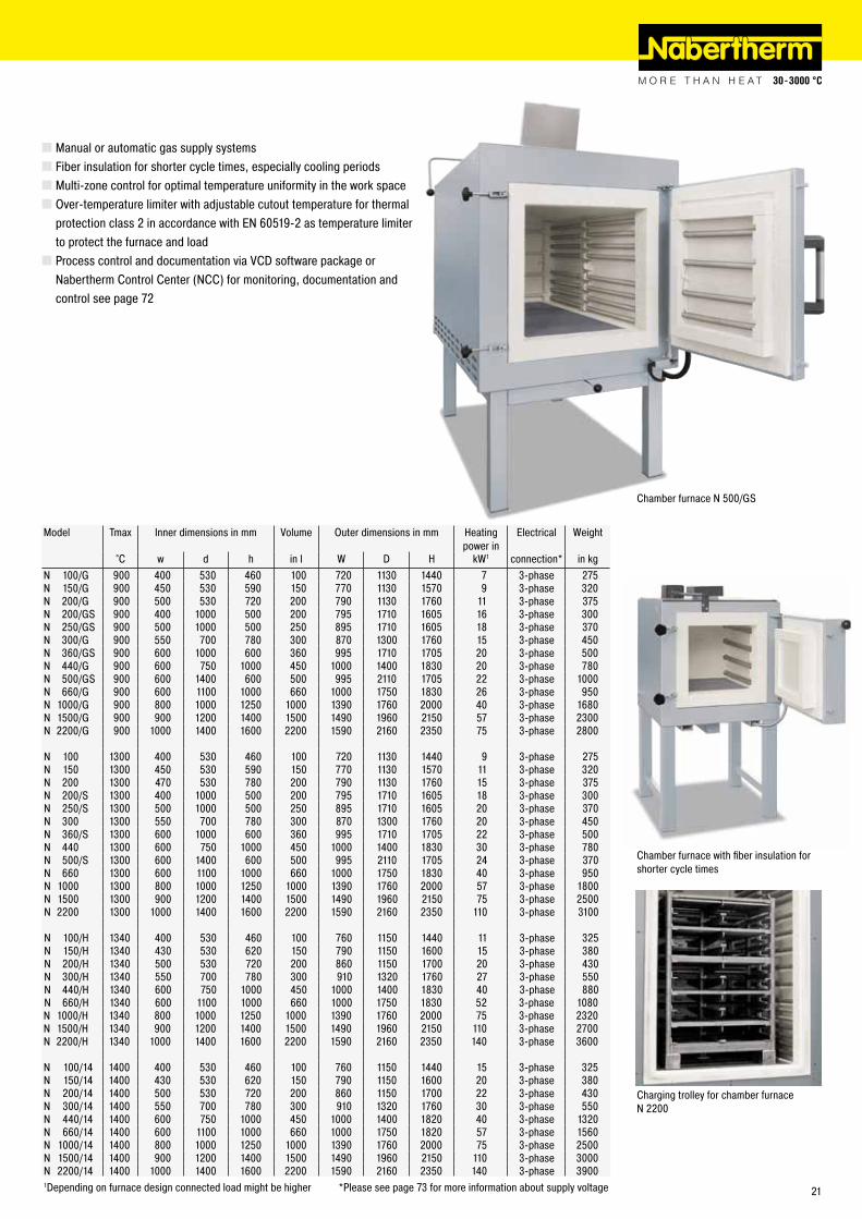
Chamber furnace with fiber insulation for shorter cycle times
Charging trolley for chamber furnace N 2200
Model Tmax Inner dimensions in mm Volume Outer dimensions in mm Heatingpower in
Electrical Weight
°C w d h in l W D H kW1 connection* in kgN 100/G 900 400 530 460 100 720 1130 1440 7 3-phase 275N 150/G 900 450 530 590 150 770 1130 1570 9 3-phase 320N 200/G 900 500 530 720 200 790 1130 1760 11 3-phase 375N 200/GS 900 400 1000 500 200 795 1710 1605 16 3-phase 300N 250/GS 900 500 1000 500 250 895 1710 1605 18 3-phase 370N 300/G 900 550 700 780 300 870 1300 1760 15 3-phase 450N 360/GS 900 600 1000 600 360 995 1710 1705 20 3-phase 500N 440/G 900 600 750 1000 450 1000 1400 1830 20 3-phase 780N 500/GS 900 600 1400 600 500 995 2110 1705 22 3-phase 1000N 660/G 900 600 1100 1000 660 1000 1750 1830 26 3-phase 950N 1000/G 900 800 1000 1250 1000 1390 1760 2000 40 3-phase 1680N 1500/G 900 900 1200 1400 1500 1490 1960 2150 57 3-phase 2300N 2200/G 900 1000 1400 1600 2200 1590 2160 2350 75 3-phase 2800
N 100 1300 400 530 460 100 720 1130 1440 9 3-phase 275N 150 1300 450 530 590 150 770 1130 1570 11 3-phase 320N 200 1300 470 530 780 200 790 1130 1760 15 3-phase 375N 200/S 1300 400 1000 500 200 795 1710 1605 18 3-phase 300N 250/S 1300 500 1000 500 250 895 1710 1605 20 3-phase 370N 300 1300 550 700 780 300 870 1300 1760 20 3-phase 450N 360/S 1300 600 1000 600 360 995 1710 1705 22 3-phase 500N 440 1300 600 750 1000 450 1000 1400 1830 30 3-phase 780N 500/S 1300 600 1400 600 500 995 2110 1705 24 3-phase 370N 660 1300 600 1100 1000 660 1000 1750 1830 40 3-phase 950N 1000 1300 800 1000 1250 1000 1390 1760 2000 57 3-phase 1800N 1500 1300 900 1200 1400 1500 1490 1960 2150 75 3-phase 2500N 2200 1300 1000 1400 1600 2200 1590 2160 2350 110 3-phase 3100
N 100/H 1340 400 530 460 100 760 1150 1440 11 3-phase 325N 150/H 1340 430 530 620 150 790 1150 1600 15 3-phase 380N 200/H 1340 500 530 720 200 860 1150 1700 20 3-phase 430N 300/H 1340 550 700 780 300 910 1320 1760 27 3-phase 550N 440/H 1340 600 750 1000 450 1000 1400 1830 40 3-phase 880N 660/H 1340 600 1100 1000 660 1000 1750 1830 52 3-phase 1080N 1000/H 1340 800 1000 1250 1000 1390 1760 2000 75 3-phase 2320N 1500/H 1340 900 1200 1400 1500 1490 1960 2150 110 3-phase 2700N 2200/H 1340 1000 1400 1600 2200 1590 2160 2350 140 3-phase 3600
N 100/14 1400 400 530 460 100 760 1150 1440 15 3-phase 325N 150/14 1400 430 530 620 150 790 1150 1600 20 3-phase 380N 200/14 1400 500 530 720 200 860 1150 1700 22 3-phase 430N 300/14 1400 550 700 780 300 910 1320 1760 30 3-phase 550N 440/14 1400 600 750 1000 450 1000 1400 1820 40 3-phase 1320N 660/14 1400 600 1100 1000 660 1000 1750 1820 57 3-phase 1560N 1000/14 1400 800 1000 1250 1000 1390 1760 2000 75 3-phase 2500N 1500/14 1400 900 1200 1400 1500 1490 1960 2150 110 3-phase 3000N 2200/14 1400 1000 1400 1600 2200 1590 2160 2350 140 3-phase 39001Depending on furnace design connected load might be higher *Please see page 73 for more information about supply voltage
� Manual or automatic gas supply systems � Fiber insulation for shorter cycle times, especially cooling periods � Multi-zone control for optimal temperature uniformity in the work space � Over-temperature limiter with adjustable cutout temperature for thermal protection class 2 in accordance with EN 60519-2 as temperature limiter to protect the furnace and load � Process control and documentation via VCD software package or Nabertherm Control Center (NCC) for monitoring, documentation and control see page 72
Chamber furnace N 500/GS
21
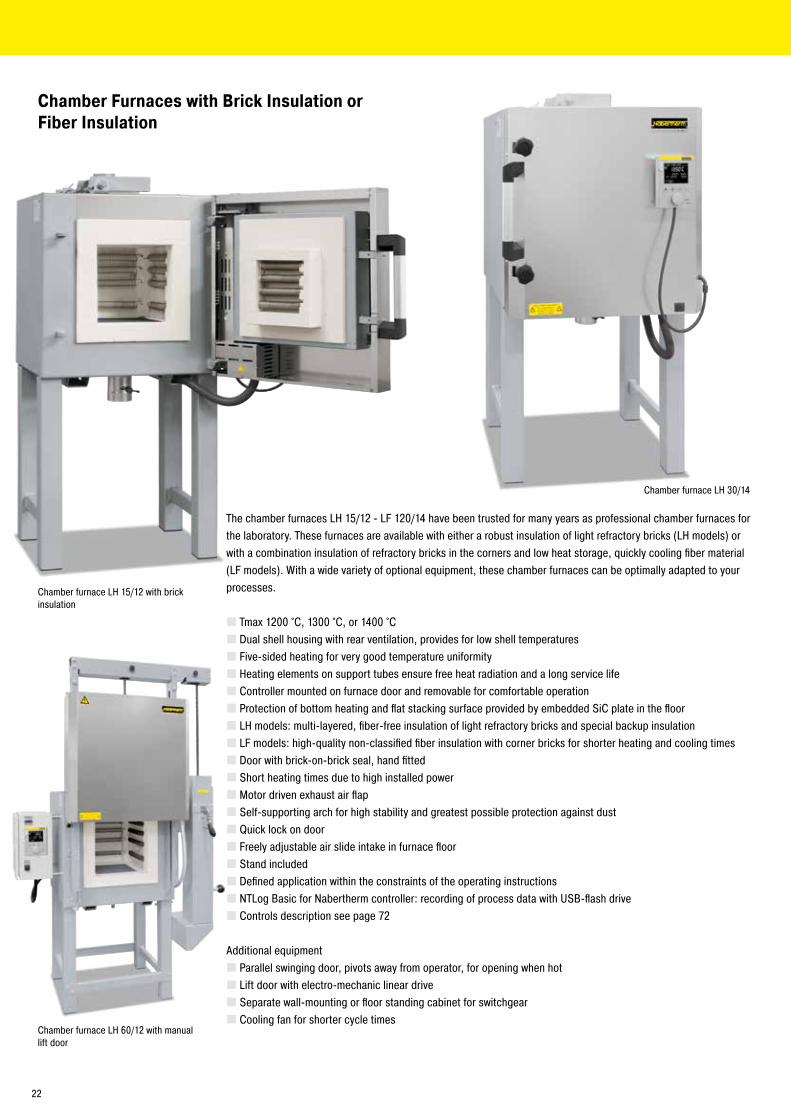
Chamber Furnaces with Brick Insulation or Fiber Insulation
The chamber furnaces LH 15/12 - LF 120/14 have been trusted for many years as professional chamber furnaces for the laboratory. These furnaces are available with either a robust insulation of light refractory bricks (LH models) or with a combination insulation of refractory bricks in the corners and low heat storage, quickly cooling fiber material (LF models). With a wide variety of optional equipment, these chamber furnaces can be optimally adapted to your processes.
� Tmax 1200 °C, 1300 °C, or 1400 °C � Dual shell housing with rear ventilation, provides for low shell temperatures � Five-sided heating for very good temperature uniformity � Heating elements on support tubes ensure free heat radiation and a long service life � Controller mounted on furnace door and removable for comfortable operation � Protection of bottom heating and flat stacking surface provided by embedded SiC plate in the floor � LH models: multi-layered, fiber-free insulation of light refractory bricks and special backup insulation � LF models: high-quality non-classified fiber insulation with corner bricks for shorter heating and cooling times � Door with brick-on-brick seal, hand fitted � Short heating times due to high installed power � Motor driven exhaust air flap � Self-supporting arch for high stability and greatest possible protection against dust � Quick lock on door � Freely adjustable air slide intake in furnace floor � Stand included � Defined application within the constraints of the operating instructions � NTLog Basic for Nabertherm controller: recording of process data with USB-flash drive � Controls description see page 72
Additional equipment � Parallel swinging door, pivots away from operator, for opening when hot � Lift door with electro-mechanic linear drive � Separate wall-mounting or floor standing cabinet for switchgear � Cooling fan for shorter cycle times
Chamber furnace LH 15/12 with brick insulation
Chamber furnace LH 60/12 with manual lift door
Chamber furnace LH 30/14
22
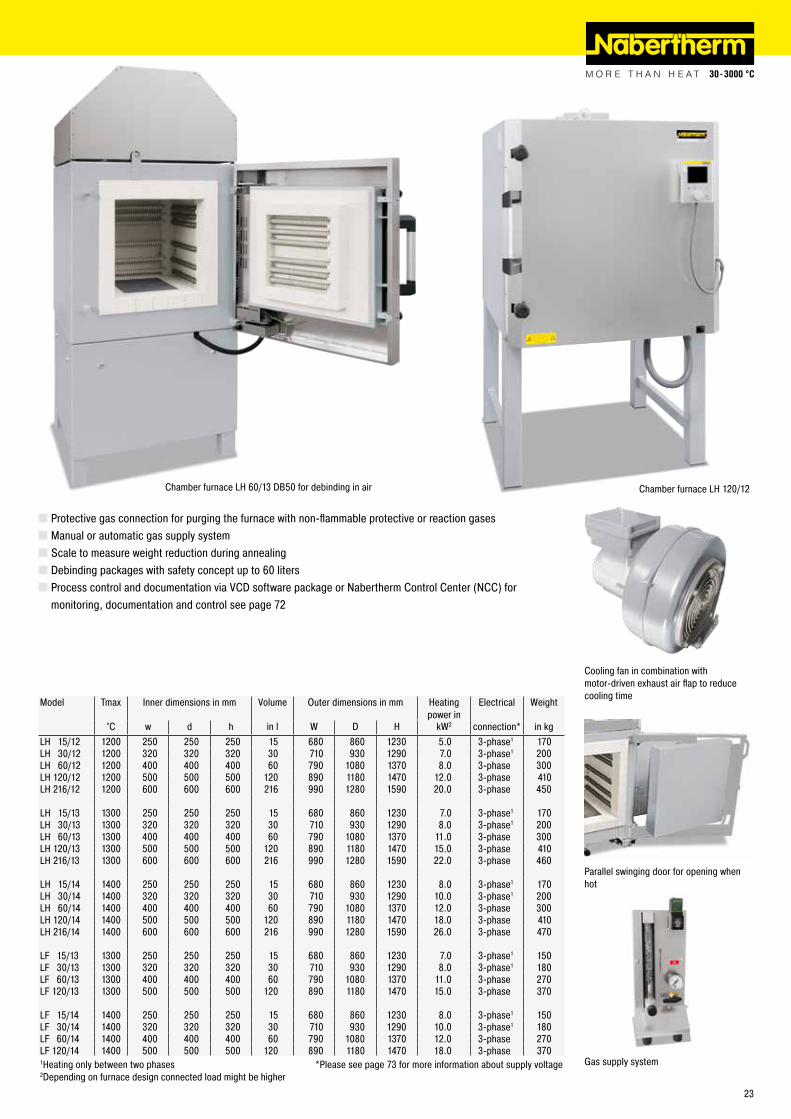
Cooling fan in combination with motor-driven exhaust air flap to reduce cooling time
Parallel swinging door for opening whenhot
Chamber furnace LH 60/13 DB50 for debinding in air
Model Tmax Inner dimensions in mm Volume Outer dimensions in mm Heating power in
Electrical Weight
°C w d h in l W D H kW2 connection* in kgLH 15/12 1200 250 250 250 15 680 860 1230 5.0 3-phase1 170LH 30/12 1200 320 320 320 30 710 930 1290 7.0 3-phase1 200LH 60/12 1200 400 400 400 60 790 1080 1370 8.0 3-phase 300LH 120/12 1200 500 500 500 120 890 1180 1470 12.0 3-phase 410LH 216/12 1200 600 600 600 216 990 1280 1590 20.0 3-phase 450
LH 15/13 1300 250 250 250 15 680 860 1230 7.0 3-phase1 170LH 30/13 1300 320 320 320 30 710 930 1290 8.0 3-phase1 200LH 60/13 1300 400 400 400 60 790 1080 1370 11.0 3-phase 300LH 120/13 1300 500 500 500 120 890 1180 1470 15.0 3-phase 410LH 216/13 1300 600 600 600 216 990 1280 1590 22.0 3-phase 460
LH 15/14 1400 250 250 250 15 680 860 1230 8.0 3-phase1 170LH 30/14 1400 320 320 320 30 710 930 1290 10.0 3-phase1 200LH 60/14 1400 400 400 400 60 790 1080 1370 12.0 3-phase 300LH 120/14 1400 500 500 500 120 890 1180 1470 18.0 3-phase 410LH 216/14 1400 600 600 600 216 990 1280 1590 26.0 3-phase 470
LF 15/13 1300 250 250 250 15 680 860 1230 7.0 3-phase1 150LF 30/13 1300 320 320 320 30 710 930 1290 8.0 3-phase1 180LF 60/13 1300 400 400 400 60 790 1080 1370 11.0 3-phase 270LF 120/13 1300 500 500 500 120 890 1180 1470 15.0 3-phase 370
LF 15/14 1400 250 250 250 15 680 860 1230 8.0 3-phase1 150LF 30/14 1400 320 320 320 30 710 930 1290 10.0 3-phase1 180LF 60/14 1400 400 400 400 60 790 1080 1370 12.0 3-phase 270LF 120/14 1400 500 500 500 120 890 1180 1470 18.0 3-phase 3701Heating only between two phases *Please see page 73 for more information about supply voltage2Depending on furnace design connected load might be higher
Gas supply system
� Protective gas connection for purging the furnace with non-flammable protective or reaction gases � Manual or automatic gas supply system � Scale to measure weight reduction during annealing � Debinding packages with safety concept up to 60 liters � Process control and documentation via VCD software package or Nabertherm Control Center (NCC) for monitoring, documentation and control see page 72
Chamber furnace LH 120/12
23
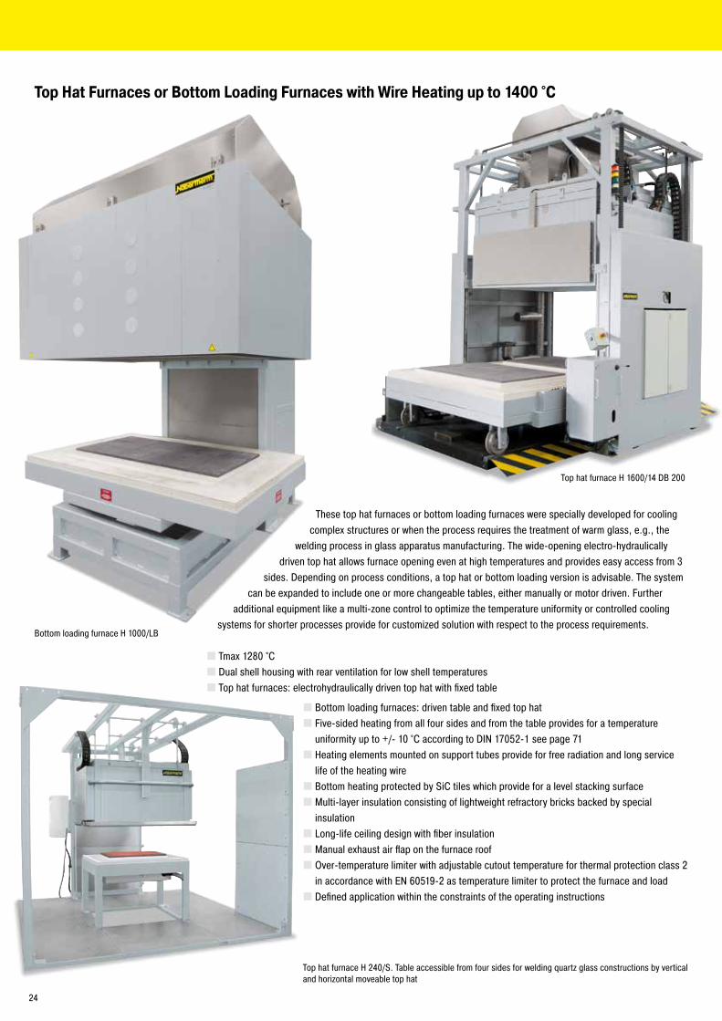
Top hat furnace H 240/S. Table accessible from four sides for welding quartz glass constructions by vertical and horizontal moveable top hat
Top Hat Furnaces or Bottom Loading Furnaces with Wire Heating up to 1400 °C
These top hat furnaces or bottom loading furnaces were specially developed for cooling complex structures or when the process requires the treatment of warm glass, e.g., the
welding process in glass apparatus manufacturing. The wide-opening electro-hydraulically driven top hat allows furnace opening even at high temperatures and provides easy access from 3
sides. Depending on process conditions, a top hat or bottom loading version is advisable. The system can be expanded to include one or more changeable tables, either manually or motor driven. Further
additional equipment like a multi-zone control to optimize the temperature uniformity or controlled cooling systems for shorter processes provide for customized solution with respect to the process requirements.
� Tmax 1280 °C � Dual shell housing with rear ventilation for low shell temperatures � Top hat furnaces: electrohydraulically driven top hat with fixed table
� Bottom loading furnaces: driven table and fixed top hat � Five-sided heating from all four sides and from the table provides for a temperature uniformity up to +/- 10 °C according to DIN 17052-1 see page 71 � Heating elements mounted on support tubes provide for free radiation and long service life of the heating wire � Bottom heating protected by SiC tiles which provide for a level stacking surface � Multi-layer insulation consisting of lightweight refractory bricks backed by special insulation � Long-life ceiling design with fiber insulation � Manual exhaust air flap on the furnace roof � Over-temperature limiter with adjustable cutout temperature for thermal protection class 2 in accordance with EN 60519-2 as temperature limiter to protect the furnace and load � Defined application within the constraints of the operating instructions
Bottom loading furnace H 1000/LB
Top hat furnace H 1600/14 DB 200
24
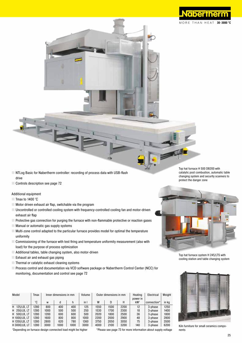
� NTLog Basic for Nabertherm controller: recording of process data with USB-flash drive � Controls description see page 72
Additional equipment � Tmax to 1400 °C � Motor driven exhaust air flap, switchable via the program � Uncontrolled or controlled cooling system with frequency-controlled cooling fan and motor-driven exhaust air flap � Protective gas connection for purging the furnace with non-flammable protective or reaction gases � Manual or automatic gas supply systems � Multi-zone control adapted to the particular furnace provides model for optimal the temperature uniformity � Commissioning of the furnace with test firing and temperature uniformity measurement (also with load) for the purpose of process optimization � Additional tables, table changing system, also motor-driven � Exhaust air and exhaust gas piping � Thermal or catalytic exhaust cleaning systems � Process control and documentation via VCD software package or Nabertherm Control Center (NCC) for monitoring, documentation and control see page 72
Top hat furnace system H 245/LTS with cooling station and table changing system
Kiln furniture for small ceramics compo-nents
Model Tmax Inner dimensions in mm Volume Outer dimensions in mm Heatingpower in
Electrical Weight
°C w d h in l W D H kW1 connection* in kgH 125/LB, LT 1280 800 400 400 125 1550 1500 2200 12 3-phase 1250H 250/LB, LT 1280 1000 500 500 250 1530 1700 2300 18 3-phase 1400H 500/LB, LT 1280 1200 600 600 500 2020 1800 2500 36 3-phase 1800H 1000/LB, LT 1280 1600 800 800 1000 2200 2000 2900 48 3-phase 2800H 1350/LB, LT 1280 2800 620 780 1360 3750 2050 3050 75 3-phase 3500H 3000/LB, LT 1280 3000 1000 1000 3000 4000 2100 3200 140 3-phase 62001Depending on furnace design connected load might be higher *Please see page 73 for more information about supply voltage
Top hat furnace H 500 DB200 with catalytic post combustion, automatic table changing system and security scanners to protect the danger zone
Top hat furnace H 1600/14 DB 200
25
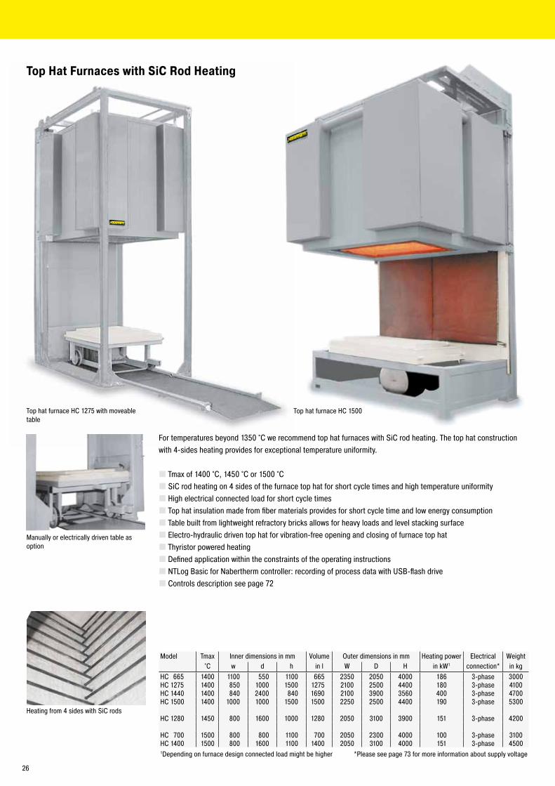
Top hat furnace HC 1275 with moveable table
Heating from 4 sides with SiC rods
Top Hat Furnaces with SiC Rod Heating
Manually or electrically driven table as option
For temperatures beyond 1350 °C we recommend top hat furnaces with SiC rod heating. The top hat construction with 4-sides heating provides for exceptional temperature uniformity.
� Tmax of 1400 °C, 1450 °C or 1500 °C � SiC rod heating on 4 sides of the furnace top hat for short cycle times and high temperature uniformity � High electrical connected load for short cycle times � Top hat insulation made from fiber materials provides for short cycle time and low energy consumption � Table built from lightweight refractory bricks allows for heavy loads and level stacking surface � Electro-hydraulic driven top hat for vibration-free opening and closing of furnace top hat � Thyristor powered heating � Defined application within the constraints of the operating instructions � NTLog Basic for Nabertherm controller: recording of process data with USB-flash drive � Controls description see page 72
Model Tmax Inner dimensions in mm Volume Outer dimensions in mm Heating power Electrical Weight°C w d h in l W D H in kW1 connection* in kg
HC 665 1400 1100 550 1100 665 2350 2050 4000 186 3-phase 3000HC 1275 1400 850 1000 1500 1275 2100 2500 4400 180 3-phase 4100HC 1440 1400 840 2400 840 1690 2100 3900 3560 400 3-phase 4700HC 1500 1400 1000 1000 1500 1500 2250 2500 4400 190 3-phase 5300
HC 1280 1450 800 1600 1000 1280 2050 3100 3900 151 3-phase 4200
HC 700 1500 800 800 1100 700 2050 2300 4000 100 3-phase 3100HC 1400 1500 800 1600 1100 1400 2050 3100 4000 151 3-phase 45001Depending on furnace design connected load might be higher *Please see page 73 for more information about supply voltage
Top hat furnace HC 1500
26
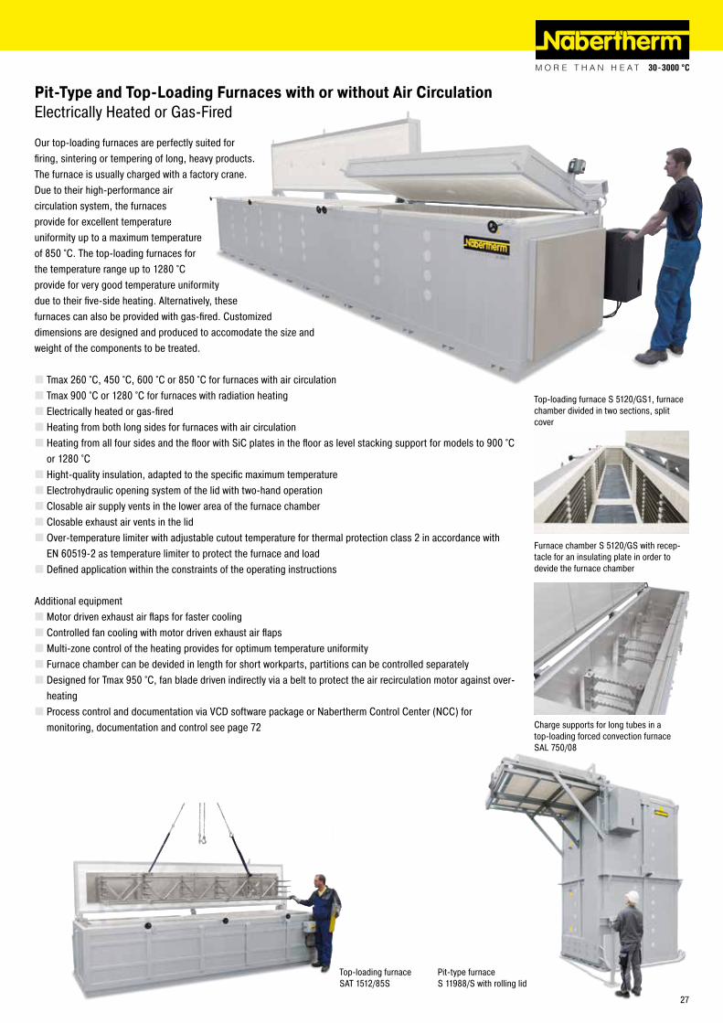
Pit-Type and Top-Loading Furnaces with or without Air Circulation Electrically Heated or Gas-Fired
Our top-loading furnaces are perfectly suited for firing, sintering or tempering of long, heavy products. The furnace is usually charged with a factory crane. Due to their high-performance air circulation system, the furnaces provide for excellent temperature uniformity up to a maximum temperature of 850 °C. The top-loading furnaces for the temperature range up to 1280 °C provide for very good temperature uniformity due to their five-side heating. Alternatively, these furnaces can also be provided with gas-fired. Customized dimensions are designed and produced to accomodate the size and weight of the components to be treated.
� Tmax 260 °C, 450 °C, 600 °C or 850 °C for furnaces with air circulation � Tmax 900 °C or 1280 °C for furnaces with radiation heating � Electrically heated or gas-fired � Heating from both long sides for furnaces with air circulation � Heating from all four sides and the floor with SiC plates in the floor as level stacking support for models to 900 °C or 1280 °C � Hight-quality insulation, adapted to the specific maximum temperature � Electrohydraulic opening system of the lid with two-hand operation � Closable air supply vents in the lower area of the furnace chamber � Closable exhaust air vents in the lid � Over-temperature limiter with adjustable cutout temperature for thermal protection class 2 in accordance with EN 60519-2 as temperature limiter to protect the furnace and load � Defined application within the constraints of the operating instructions
Additional equipment � Motor driven exhaust air flaps for faster cooling � Controlled fan cooling with motor driven exhaust air flaps � Multi-zone control of the heating provides for optimum temperature uniformity � Furnace chamber can be devided in length for short workparts, partitions can be controlled separately � Designed for Tmax 950 °C, fan blade driven indirectly via a belt to protect the air recirculation motor against over-heating � Process control and documentation via VCD software package or Nabertherm Control Center (NCC) for monitoring, documentation and control see page 72
Top-loading furnace S 5120/GS1, furnace chamber divided in two sections, split cover
Furnace chamber S 5120/GS with recep-tacle for an insulating plate in order to devide the furnace chamber
Pit-type furnace S 11988/S with rolling lid
Charge supports for long tubes in a top-loading forced convection furnace SAL 750/08
Top-loading furnace SAT 1512/85S
27
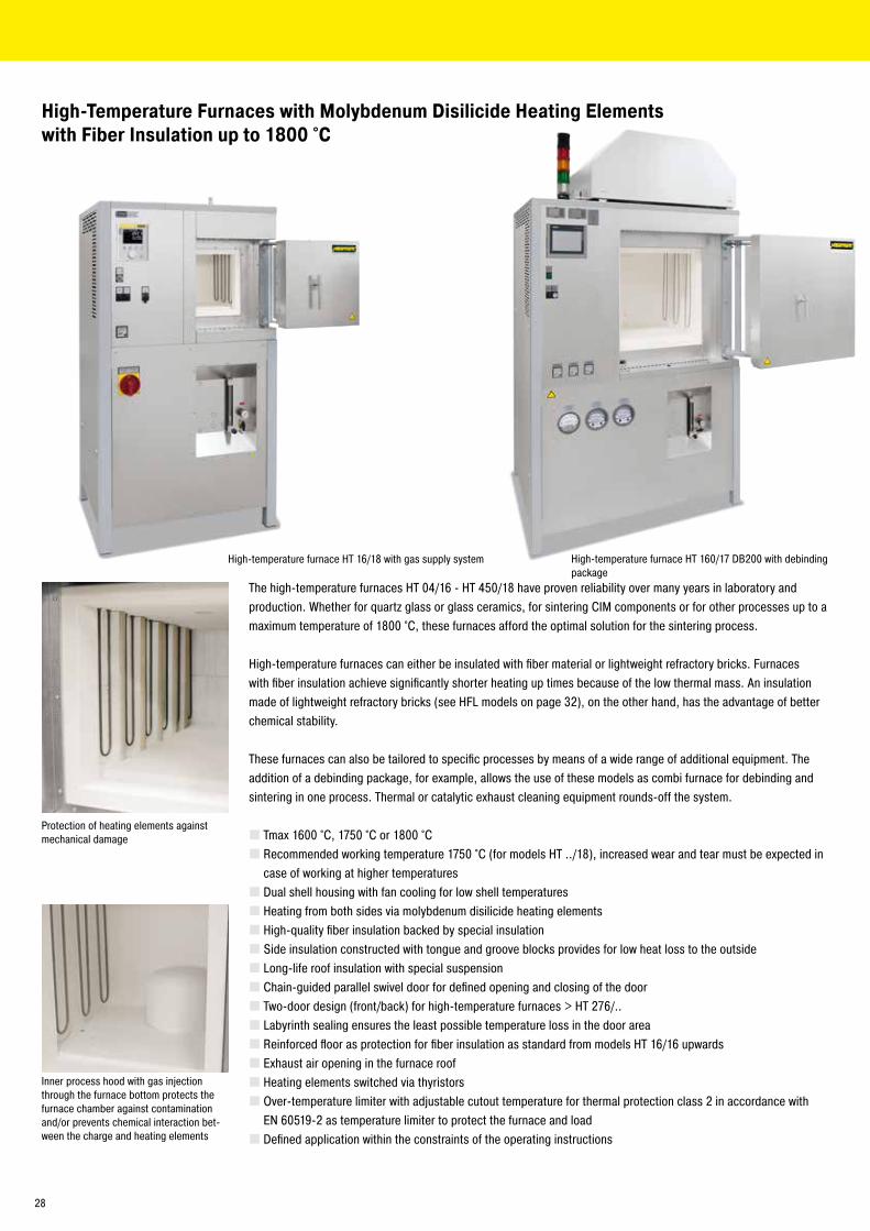
The high-temperature furnaces HT 04/16 - HT 450/18 have proven reliability over many years in laboratory and production. Whether for quartz glass or glass ceramics, for sintering CIM components or for other processes up to a maximum temperature of 1800 °C, these furnaces afford the optimal solution for the sintering process.
High-temperature furnaces can either be insulated with fiber material or lightweight refractory bricks. Furnaces with fiber insulation achieve significantly shorter heating up times because of the low thermal mass. An insulation made of lightweight refractory bricks (see HFL models on page 32), on the other hand, has the advantage of better chemical stability.
These furnaces can also be tailored to specific processes by means of a wide range of additional equipment. The addition of a debinding package, for example, allows the use of these models as combi furnace for debinding and sintering in one process. Thermal or catalytic exhaust cleaning equipment rounds-off the system.
� Tmax 1600 °C, 1750 °C or 1800 °C � Recommended working temperature 1750 °C (for models HT ../18), increased wear and tear must be expected in case of working at higher temperatures � Dual shell housing with fan cooling for low shell temperatures � Heating from both sides via molybdenum disilicide heating elements � High-quality fiber insulation backed by special insulation � Side insulation constructed with tongue and groove blocks provides for low heat loss to the outside � Long-life roof insulation with special suspension � Chain-guided parallel swivel door for defined opening and closing of the door � Two-door design (front/back) for high-temperature furnaces > HT 276/.. � Labyrinth sealing ensures the least possible temperature loss in the door area � Reinforced floor as protection for fiber insulation as standard from models HT 16/16 upwards � Exhaust air opening in the furnace roof � Heating elements switched via thyristors � Over-temperature limiter with adjustable cutout temperature for thermal protection class 2 in accordance with EN 60519-2 as temperature limiter to protect the furnace and load � Defined application within the constraints of the operating instructions
Protection of heating elements against mechanical damage
High-temperature furnace HT 16/18 with gas supply system
Inner process hood with gas injection through the furnace bottom protects the furnace chamber against contamination and/or prevents chemical interaction bet-ween the charge and heating elements
High-temperature furnace HT 160/17 DB200 with debinding package
High-Temperature Furnaces with Molybdenum Disilicide Heating Elements with Fiber Insulation up to 1800 °C
28
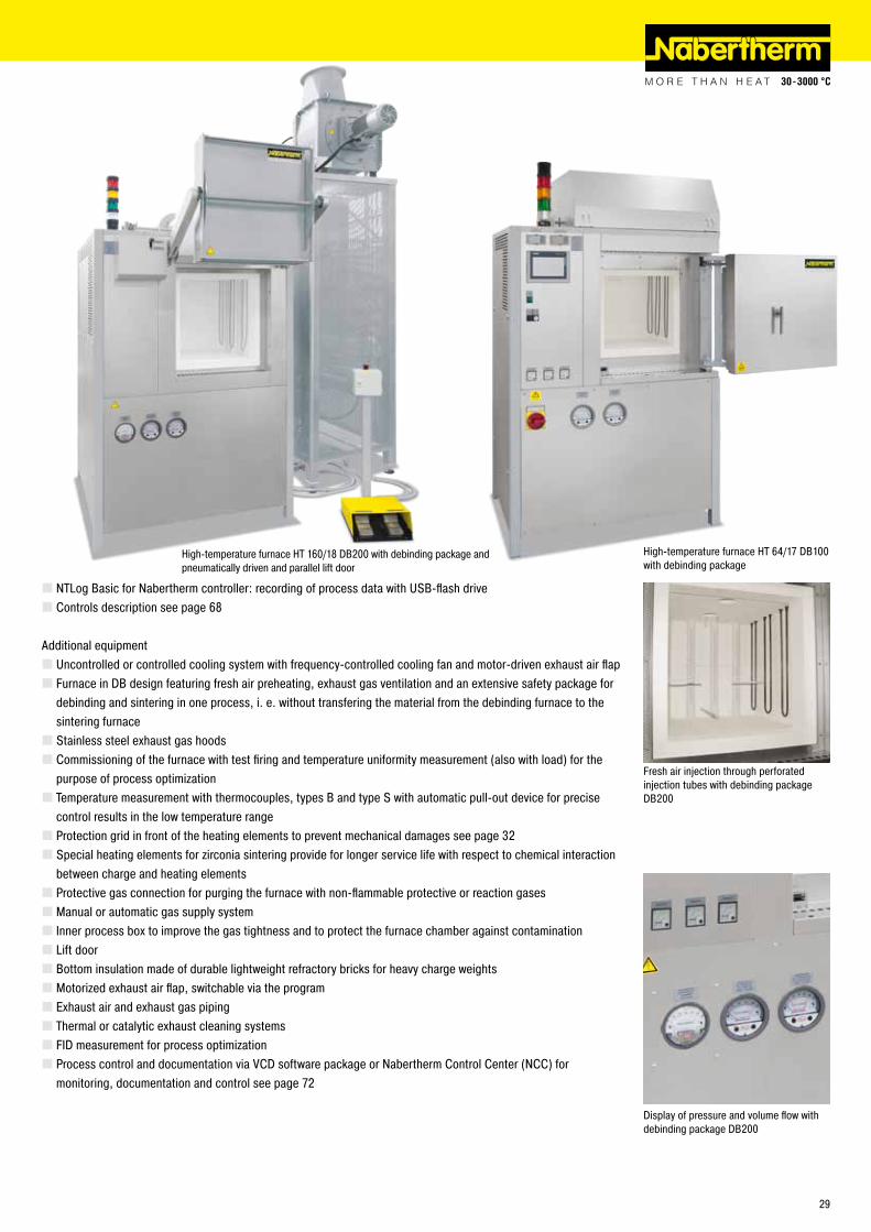
� NTLog Basic for Nabertherm controller: recording of process data with USB-flash drive � Controls description see page 68
Additional equipment � Uncontrolled or controlled cooling system with frequency-controlled cooling fan and motor-driven exhaust air flap � Furnace in DB design featuring fresh air preheating, exhaust gas ventilation and an extensive safety package for debinding and sintering in one process, i. e. without transfering the material from the debinding furnace to the sintering furnace � Stainless steel exhaust gas hoods � Commissioning of the furnace with test firing and temperature uniformity measurement (also with load) for the purpose of process optimization � Temperature measurement with thermocouples, types B and type S with automatic pull-out device for precise control results in the low temperature range � Protection grid in front of the heating elements to prevent mechanical damages see page 32 � Special heating elements for zirconia sintering provide for longer service life with respect to chemical interaction between charge and heating elements � Protective gas connection for purging the furnace with non-flammable protective or reaction gases � Manual or automatic gas supply system � Inner process box to improve the gas tightness and to protect the furnace chamber against contamination � Lift door � Bottom insulation made of durable lightweight refractory bricks for heavy charge weights � Motorized exhaust air flap, switchable via the program � Exhaust air and exhaust gas piping � Thermal or catalytic exhaust cleaning systems � FID measurement for process optimization � Process control and documentation via VCD software package or Nabertherm Control Center (NCC) for monitoring, documentation and control see page 72
Fresh air injection through perforated injection tubes with debinding package DB200
Display of pressure and volume flow with debinding package DB200
High-temperature furnace HT 160/18 DB200 with debinding package and pneumatically driven and parallel lift door
High-temperature furnace HT 64/17 DB100 with debinding package
29
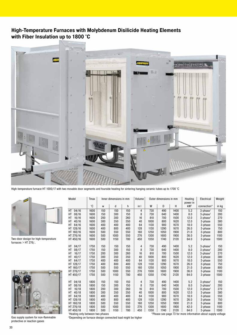
High-temperature furnace HT 1000/17 with two movable door segments and fourside heating for sintering hanging ceramic tubes up to 1700 °C
Gas supply system for non-flammable protective or reaction gases
Model Tmax Inner dimensions in mm Volume Outer dimensions in mm Heating power in
Electrical Weight
°C w d h in l W D H kW2 connection* in kgHT 04/16 1600 150 150 150 4 730 490 1400 5.2 3-phase1 150HT 08/16 1600 150 300 150 8 730 640 1400 8.0 3-phase1 200HT 16/16 1600 200 300 260 16 810 700 1500 12.0 3-phase1 270HT 40/16 1600 300 350 350 40 1000 800 1620 12.0 3-phase 380HT 64/16 1600 400 400 400 64 1130 900 1670 18.0 3-phase 550HT 128/16 1600 400 800 400 128 1130 1290 1670 26.0 3-phase 750HT 160/16 1600 500 550 550 160 1250 1050 1900 21.0 3-phase 800HT 276/16 1600 500 1000 550 276 1300 1600 1900 36.0 3-phase 1100HT 450/16 1600 500 1150 780 450 1350 1740 2120 64.0 3-phase 1500
HT 04/17 1750 150 150 150 4 730 490 1400 5.2 3-phase1 150HT 08/17 1750 150 300 150 8 730 640 1400 8.0 3-phase1 200HT 16/17 1750 200 300 260 16 810 700 1500 12.0 3-phase1 270HT 40/17 1750 300 350 350 40 1000 800 1620 12.0 3-phase 380HT 64/17 1750 400 400 400 64 1130 900 1670 18.0 3-phase 550HT 128/17 1750 400 800 400 128 1130 1290 1670 26.0 3-phase 750HT 160/17 1750 500 550 550 160 1250 1050 1900 21.0 3-phase 800HT 276/17 1750 500 1000 550 276 1300 1600 1900 36.0 3-phase 1100HT 450/17 1750 500 1150 780 450 1350 1740 2120 64.0 3-phase 1500
HT 04/18 1800 150 150 150 4 730 490 1400 5.2 3-phase1 150HT 08/18 1800 150 300 150 8 730 640 1400 8.0 3-phase1 200HT 16/18 1800 200 300 260 16 810 700 1500 12.0 3-phase1 270HT 40/18 1800 300 350 350 40 1000 800 1620 12.0 3-phase 380HT 64/18 1800 400 400 400 64 1130 900 1670 18.0 3-phase 550HT 128/18 1800 400 800 400 128 1130 1290 1670 26.0 3-phase 750HT 160/18 1800 500 550 550 160 1250 1050 1900 21.0 3-phase 800HT 276/18 1800 500 1000 550 276 1300 1600 1900 42.0 3-phase 1100HT 450/18 1800 500 1150 780 450 1350 1740 2120 64.0 3-phase 15001Heating only between two phases *Please see page 73 for more information about supply voltage2Depending on furnace design connected load might be higher
Two-door design for high-temperature furnaces > HT 276/..
High-Temperature Furnaces with Molybdenum Disilicide Heating Elements with Fiber Insulation up to 1800 °C
30
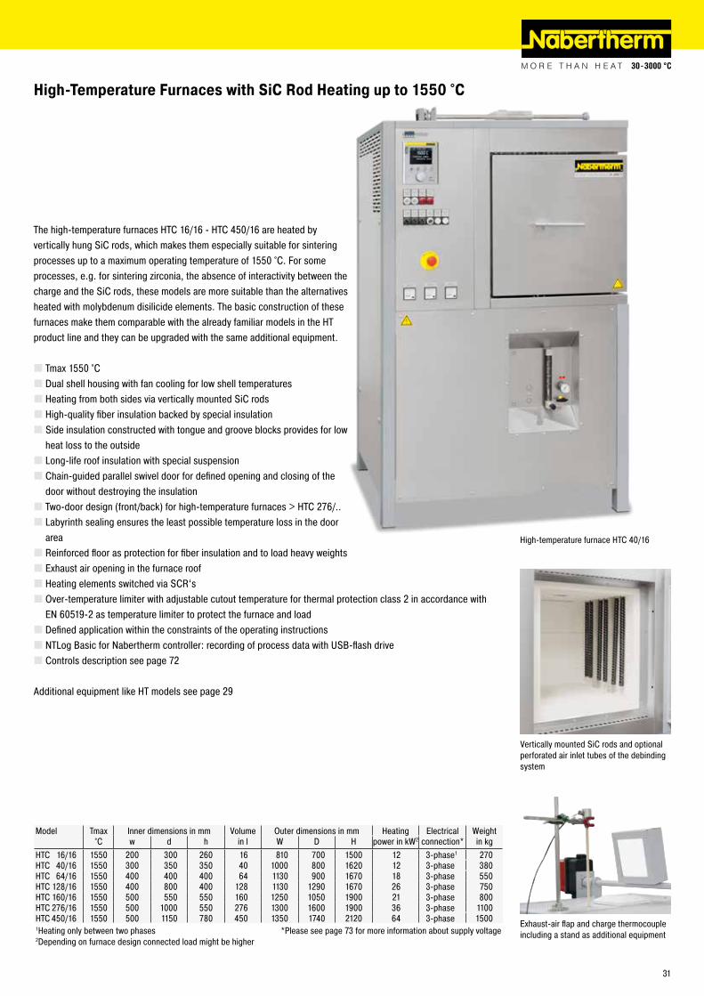
Vertically mounted SiC rods and optional perforated air inlet tubes of the debinding system
Exhaust-air flap and charge thermocouple including a stand as additional equipment
High-Temperature Furnaces with SiC Rod Heating up to 1550 °C
Model Tmax Inner dimensions in mm Volume Outer dimensions in mm Heating Electrical Weight°C w d h in l W D H power in kW2 connection* in kg
HTC 16/16 1550 200 300 260 16 810 700 1500 12 3-phase1 270HTC 40/16 1550 300 350 350 40 1000 800 1620 12 3-phase 380HTC 64/16 1550 400 400 400 64 1130 900 1670 18 3-phase 550HTC 128/16 1550 400 800 400 128 1130 1290 1670 26 3-phase 750HTC 160/16 1550 500 550 550 160 1250 1050 1900 21 3-phase 800HTC 276/16 1550 500 1000 550 276 1300 1600 1900 36 3-phase 1100HTC 450/16 1550 500 1150 780 450 1350 1740 2120 64 3-phase 15001Heating only between two phases *Please see page 73 for more information about supply voltage2Depending on furnace design connected load might be higher
The high-temperature furnaces HTC 16/16 - HTC 450/16 are heated by vertically hung SiC rods, which makes them especially suitable for sintering processes up to a maximum operating temperature of 1550 °C. For some processes, e.g. for sintering zirconia, the absence of interactivity between the charge and the SiC rods, these models are more suitable than the alternatives heated with molybdenum disilicide elements. The basic construction of these furnaces make them comparable with the already familiar models in the HT product line and they can be upgraded with the same additional equipment.
� Tmax 1550 °C � Dual shell housing with fan cooling for low shell temperatures � Heating from both sides via vertically mounted SiC rods � High-quality fiber insulation backed by special insulation � Side insulation constructed with tongue and groove blocks provides for low heat loss to the outside � Long-life roof insulation with special suspension � Chain-guided parallel swivel door for defined opening and closing of the door without destroying the insulation � Two-door design (front/back) for high-temperature furnaces > HTC 276/.. � Labyrinth sealing ensures the least possible temperature loss in the door area � Reinforced floor as protection for fiber insulation and to load heavy weights � Exhaust air opening in the furnace roof � Heating elements switched via SCR‘s � Over-temperature limiter with adjustable cutout temperature for thermal protection class 2 in accordance with EN 60519-2 as temperature limiter to protect the furnace and load � Defined application within the constraints of the operating instructions � NTLog Basic for Nabertherm controller: recording of process data with USB-flash drive � Controls description see page 72
Additional equipment like HT models see page 29
High-temperature furnace HTC 40/16
31
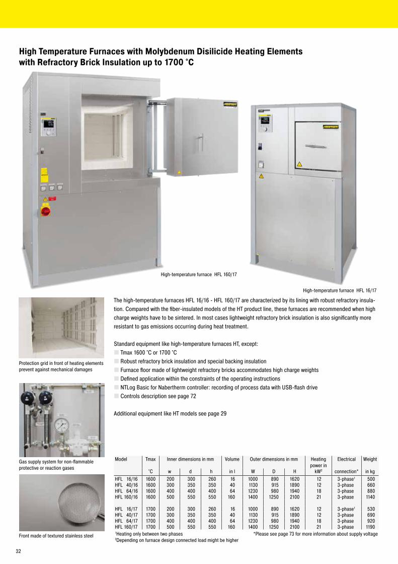
High Temperature Furnaces with Molybdenum Disilicide Heating Elements with Refractory Brick Insulation up to 1700 °C
Protection grid in front of heating elements prevent against mechanical damages
Gas supply system for non-flammable protective or reaction gases
The high-temperature furnaces HFL 16/16 - HFL 160/17 are characterized by its lining with robust refractory insula-tion. Compared with the fiber-insulated models of the HT product line, these furnaces are recommended when high charge weights have to be sintered. In most cases lightweight refractory brick insulation is also significantly more resistant to gas emissions occurring during heat treatment.
Standard equipment like high-temperature furnaces HT, except: � Tmax 1600 °C or 1700 °C � Robust refractory brick insulation and special backing insulation � Furnace floor made of lightweight refractory bricks accommodates high charge weights � Defined application within the constraints of the operating instructions � NTLog Basic for Nabertherm controller: recording of process data with USB-flash drive � Controls description see page 72
Additional equipment like HT models see page 29
Model Tmax Inner dimensions in mm Volume Outer dimensions in mm Heating power in
Electrical Weight
°C w d h in l W D H kW2 connection* in kgHFL 16/16 1600 200 300 260 16 1000 890 1620 12 3-phase1 500HFL 40/16 1600 300 350 350 40 1130 915 1890 12 3-phase 660HFL 64/16 1600 400 400 400 64 1230 980 1940 18 3-phase 880HFL 160/16 1600 500 550 550 160 1400 1250 2100 21 3-phase 1140
HFL 16/17 1700 200 300 260 16 1000 890 1620 12 3-phase1 530HFL 40/17 1700 300 350 350 40 1130 915 1890 12 3-phase 690HFL 64/17 1700 400 400 400 64 1230 980 1940 18 3-phase 920HFL 160/17 1700 500 550 550 160 1400 1250 2100 21 3-phase 11901Heating only between two phases *Please see page 73 for more information about supply voltage2Depending on furnace design connected load might be higher
Front made of textured stainless steel
High-temperature furnace HFL 160/17
High-temperature furnace HFL 16/17
32
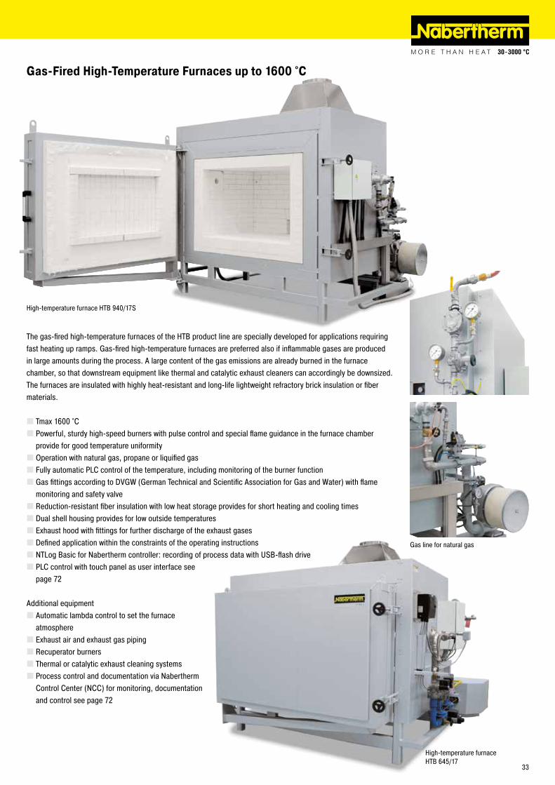
Gas-Fired High-Temperature Furnaces up to 1600 °C
The gas-fired high-temperature furnaces of the HTB product line are specially developed for applications requiring fast heating up ramps. Gas-fired high-temperature furnaces are preferred also if inflammable gases are produced in large amounts during the process. A large content of the gas emissions are already burned in the furnace chamber, so that downstream equipment like thermal and catalytic exhaust cleaners can accordingly be downsized. The furnaces are insulated with highly heat-resistant and long-life lightweight refractory brick insulation or fiber materials.
� Tmax 1600 °C � Powerful, sturdy high-speed burners with pulse control and special flame guidance in the furnace chamber provide for good temperature uniformity � Operation with natural gas, propane or liquified gas � Fully automatic PLC control of the temperature, including monitoring of the burner function � Gas fittings according to DVGW (German Technical and Scientific Association for Gas and Water) with flame monitoring and safety valve � Reduction-resistant fiber insulation with low heat storage provides for short heating and cooling times � Dual shell housing provides for low outside temperatures � Exhaust hood with fittings for further discharge of the exhaust gases � Defined application within the constraints of the operating instructions � NTLog Basic for Nabertherm controller: recording of process data with USB-flash drive � PLC control with touch panel as user interface see page 72
Additional equipment � Automatic lambda control to set the furnace atmosphere � Exhaust air and exhaust gas piping � Recuperator burners � Thermal or catalytic exhaust cleaning systems � Process control and documentation via Nabertherm Control Center (NCC) for monitoring, documentation and control see page 72
Gas line for natural gas
High-temperature furnace HTB 940/17S
High-temperature furnace HTB 645/17
33
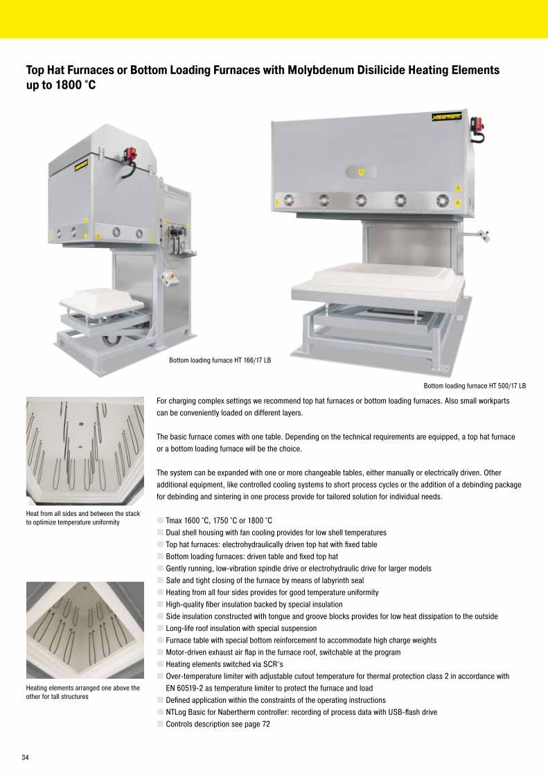
Top Hat Furnaces or Bottom Loading Furnaces with Molybdenum Disilicide Heating Elements up to 1800 °C
For charging complex settings we recommend top hat furnaces or bottom loading furnaces. Also small workparts can be conveniently loaded on different layers.
The basic furnace comes with one table. Depending on the technical requirements are equipped, a top hat furnace or a bottom loading furnace will be the choice.
The system can be expanded with one or more changeable tables, either manually or electrically driven. Other additional equipment, like controlled cooling systems to short process cycles or the addition of a debinding package for debinding and sintering in one process provide for tailored solution for individual needs.
� Tmax 1600 °C, 1750 °C or 1800 °C � Dual shell housing with fan cooling provides for low shell temperatures � Top hat furnaces: electrohydraulically driven top hat with fixed table � Bottom loading furnaces: driven table and fixed top hat � Gently running, low-vibration spindle drive or electrohydraulic drive for larger models � Safe and tight closing of the furnace by means of labyrinth seal � Heating from all four sides provides for good temperature uniformity � High-quality fiber insulation backed by special insulation � Side insulation constructed with tongue and groove blocks provides for low heat dissipation to the outside � Long-life roof insulation with special suspension � Furnace table with special bottom reinforcement to accommodate high charge weights � Motor-driven exhaust air flap in the furnace roof, switchable at the program � Heating elements switched via SCR‘s � Over-temperature limiter with adjustable cutout temperature for thermal protection class 2 in accordance with EN 60519-2 as temperature limiter to protect the furnace and load � Defined application within the constraints of the operating instructions � NTLog Basic for Nabertherm controller: recording of process data with USB-flash drive � Controls description see page 72
Heat from all sides and between the stack to optimize temperature uniformity
Heating elements arranged one above the other for tall structures
Bottom loading furnace HT 166/17 LB
Bottom loading furnace HT 500/17 LB
34
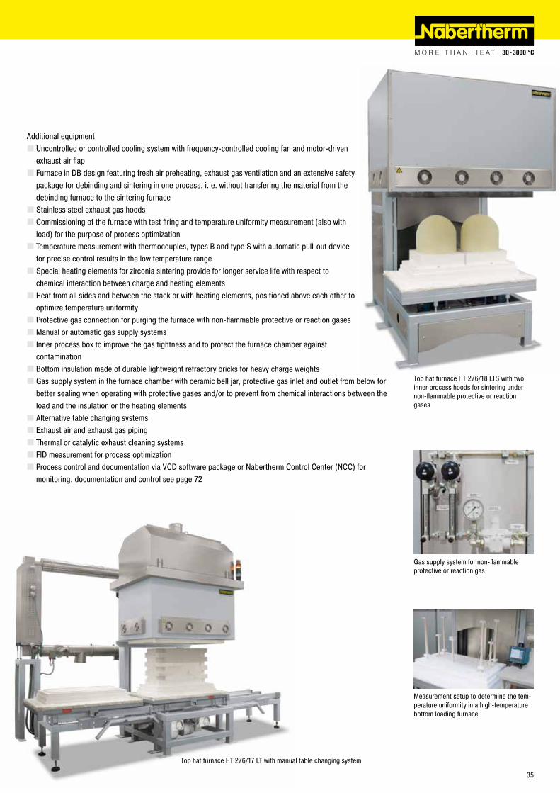
Additional equipment � Uncontrolled or controlled cooling system with frequency-controlled cooling fan and motor-driven exhaust air flap � Furnace in DB design featuring fresh air preheating, exhaust gas ventilation and an extensive safety package for debinding and sintering in one process, i. e. without transfering the material from the debinding furnace to the sintering furnace � Stainless steel exhaust gas hoods � Commissioning of the furnace with test firing and temperature uniformity measurement (also with load) for the purpose of process optimization � Temperature measurement with thermocouples, types B and type S with automatic pull-out device for precise control results in the low temperature range � Special heating elements for zirconia sintering provide for longer service life with respect to chemical interaction between charge and heating elements � Heat from all sides and between the stack or with heating elements, positioned above each other to optimize temperature uniformity � Protective gas connection for purging the furnace with non-flammable protective or reaction gases � Manual or automatic gas supply systems � Inner process box to improve the gas tightness and to protect the furnace chamber against contamination � Bottom insulation made of durable lightweight refractory bricks for heavy charge weights � Gas supply system in the furnace chamber with ceramic bell jar, protective gas inlet and outlet from below for better sealing when operating with protective gases and/or to prevent from chemical interactions between the load and the insulation or the heating elements � Alternative table changing systems � Exhaust air and exhaust gas piping � Thermal or catalytic exhaust cleaning systems � FID measurement for process optimization � Process control and documentation via VCD software package or Nabertherm Control Center (NCC) for monitoring, documentation and control see page 72
Gas supply system for non-flammable protective or reaction gas
Top hat furnace HT 276/17 LT with manual table changing system
Top hat furnace HT 276/18 LTS with two inner process hoods for sintering under non-flammable protective or reaction gases
Measurement setup to determine the tem-perature uniformity in a high-temperature bottom loading furnace
35
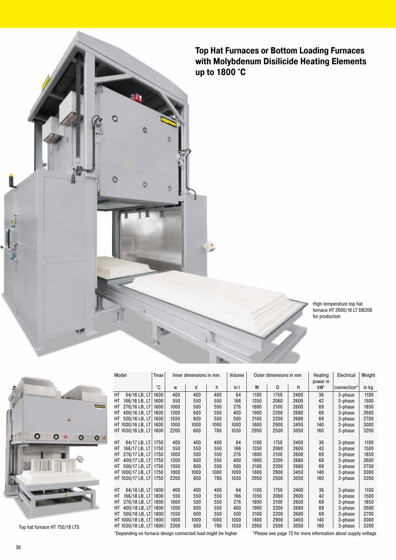
Model Tmax Inner dimensions in mm Volume Outer dimensions in mm Heatingpower in
Electrical Weight
°C w d h in l W D H kW1 connection* in kgHT 64/16 LB, LT 1600 400 400 400 64 1100 1750 2400 36 3-phase 1100HT 166/16 LB, LT 1600 550 550 550 166 1350 2060 2600 42 3-phase 1500HT 276/16 LB, LT 1600 1000 500 550 276 1800 2100 2600 69 3-phase 1850HT 400/16 LB, LT 1600 1200 600 550 400 1900 2200 2680 69 3-phase 2600HT 500/16 LB, LT 1600 1550 600 550 500 2100 2200 2680 69 3-phase 2700HT 1000/16 LB, LT 1600 1000 1000 1000 1000 1800 2900 3450 140 3-phase 3000HT 1030/16 LB, LT 1600 2200 600 780 1030 2950 2500 3050 160 3-phase 3200
HT 64/17 LB, LT 1750 400 400 400 64 1100 1750 2400 36 3-phase 1100HT 166/17 LB, LT 1750 550 550 550 166 1350 2060 2600 42 3-phase 1500HT 276/17 LB, LT 1750 1000 500 550 276 1800 2100 2600 69 3-phase 1850HT 400/17 LB, LT 1750 1200 600 550 400 1900 2200 2680 69 3-phase 2600HT 500/17 LB, LT 1750 1550 600 550 500 2100 2200 2680 69 3-phase 2700HT 1000/17 LB, LT 1750 1000 1000 1000 1000 1800 2900 3450 140 3-phase 3000HT 1030/17 LB, LT 1750 2200 600 780 1030 2950 2500 3050 160 3-phase 3200
HT 64/18 LB, LT 1800 400 400 400 64 1100 1750 2400 36 3-phase 1100HT 166/18 LB, LT 1800 550 550 550 166 1350 2060 2600 42 3-phase 1500HT 276/18 LB, LT 1800 1000 500 550 276 1800 2100 2600 69 3-phase 1850HT 400/18 LB, LT 1800 1200 600 550 400 1900 2200 2680 69 3-phase 2600HT 500/18 LB, LT 1800 1550 600 550 500 2100 2200 2680 69 3-phase 2700HT 1000/18 LB, LT 1800 1000 1000 1000 1000 1800 2900 3450 140 3-phase 3000HT 1030/18 LB, LT 1800 2200 600 780 1030 2950 2500 3050 160 3-phase 32001Depending on furnace design connected load might be higher *Please see page 73 for more information about supply voltage
Top Hat Furnaces or Bottom Loading Furnaces with Molybdenum Disilicide Heating Elements up to 1800 °C
High-temperature top hat furnace HT 2600/16 LT DB200 for production
Top hat furnace HT 750/18 LTS
36
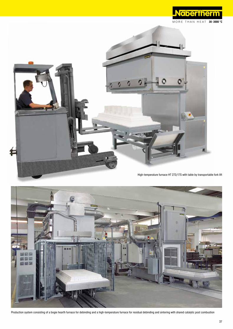
High-temperature furnace HT 273/17S with table by transportable fork lift
Production system consisting of a bogie hearth furnace for debinding and a high-temperature furnace for residual debinding and sintering with shared catalytic post combustion
37
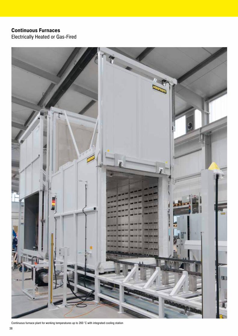
Continuous Furnaces Electrically Heated or Gas-Fired
Continuous furnace plant for working temperatures up to 260 °C with integrated cooling station
38
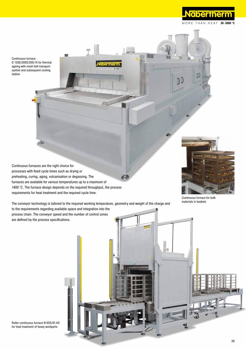
Roller continuous furnace N 650/45 AS for heat treatment of heavy workparts
Continuous furnace for bulk materials in baskets
Continuous furnace D 1500/3000/300/14 for thermal ageing with mesh belt transport system and subsequent cooling station
Continuous furnaces are the right choice for processes with fixed cycle times such as drying or preheating, curing, aging, vulcanisation or degassing. The furnaces are available for various temperatures up to a maximum of 1400 °C. The furnace design depends on the required throughput, the process requirements for heat treatment and the required cycle time.
The conveyor technology is tailored to the required working temperature, geometry and weight of the charge and to the requirements regarding available space and integration into the process chain. The conveyor speed and the number of control zones are defined by the process specifications.
39

Conveyor plant D 1600/3100/1200/55, consisting of solution annealing furnace, cooling station and conveyor system
Mesh belt drive in a continuous furnace
Conveyor concepts � Conveyor belt � Metal conveyor belt with adjusted mesh gauges � Drive chain � Roller conveyors � Paternoster � Pusher-type � Rotary hearth
Continuous furnace D 700/10000/300/45S with chain conveyor for 950 °C, gas-fired
Continuous Furnaces Electrically Heated or Gas-Fired
Heating systems � Electric heating, radiation or convection � Direct or indirect gas-fired
� Infrared heating � Heating with the use of external heat sources
40
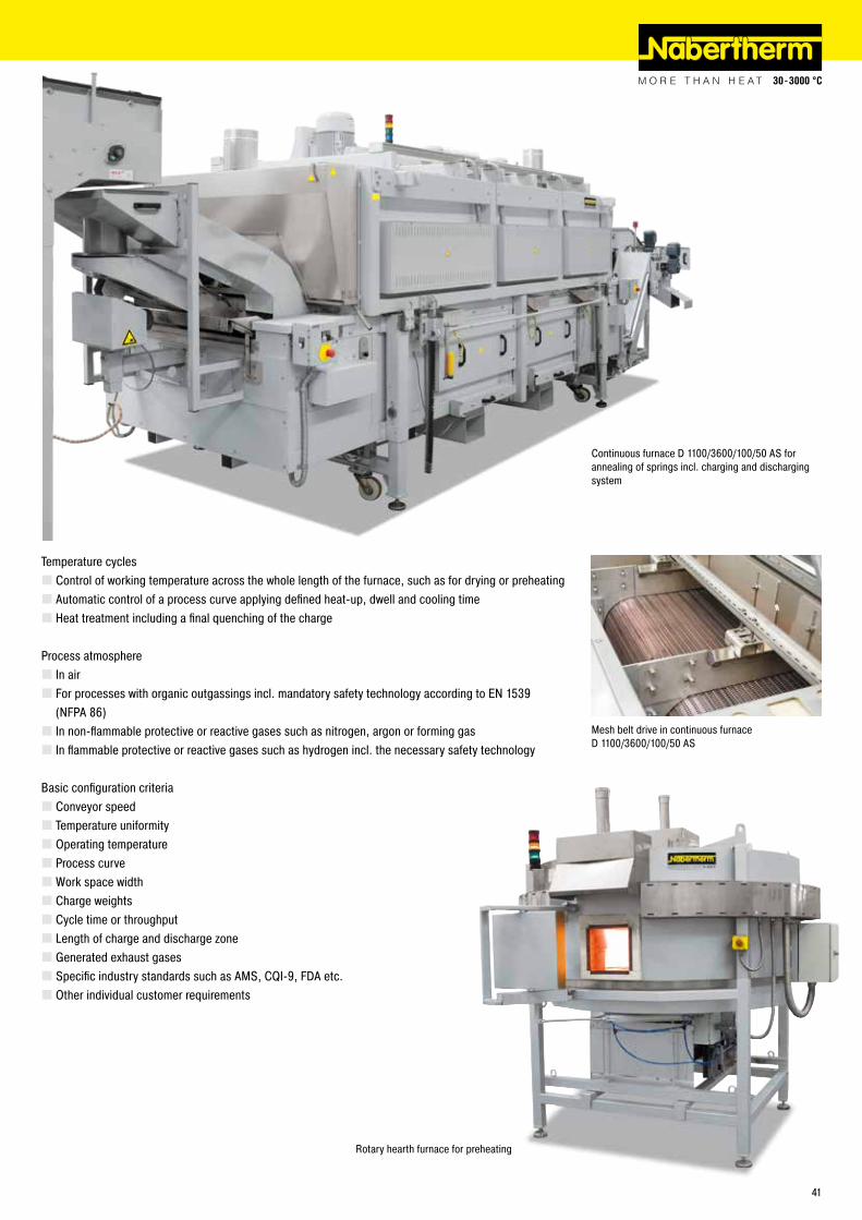
Temperature cycles � Control of working temperature across the whole length of the furnace, such as for drying or preheating � Automatic control of a process curve applying defined heat-up, dwell and cooling time � Heat treatment including a final quenching of the charge
Process atmosphere � In air � For processes with organic outgassings incl. mandatory safety technology according to EN 1539 (NFPA 86) � In non-flammable protective or reactive gases such as nitrogen, argon or forming gas � In flammable protective or reactive gases such as hydrogen incl. the necessary safety technology
Basic configuration criteria � Conveyor speed � Temperature uniformity � Operating temperature � Process curve �Work space width � Charge weights � Cycle time or throughput � Length of charge and discharge zone � Generated exhaust gases � Specific industry standards such as AMS, CQI-9, FDA etc. � Other individual customer requirements
Continuous furnace D 1100/3600/100/50 AS for annealing of springs incl. charging and discharging system
Mesh belt drive in continuous furnace D 1100/3600/100/50 AS
Rotary hearth furnace for preheating
41
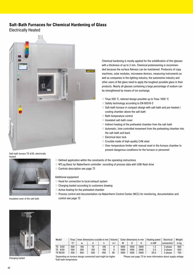
Chemical hardening is mostly applied for the solidification of thin glasses with a thickness of up to 3 mm. Chemical pretensioning is recommen-ded because the surface flatness can be maintained. Producers of copy machines, solar modules, microwave devices, measuring instruments as well as companies in the lighting industry, the automotive industry and other users of flat glass need to apply the toughest possible glass in their products. Nearly all glasses containing a large percentage of sodium can be strengthened by means of ion exchange.
� Tmax 500 °C, tailored design possible up to Tmax 1000 °C � Safety technology according to EN 60519-2 � Salt-bath furnace in compact design with salt-bath and pre-heated-/cooling chamber above the salt-bath � Bath temperature control � Insulated salt-bath cover � Indirect heating of the preheated chamber from the salt-bath � Automatic, time controlled movement from the preheating chamber into the salt-bath and back � Electrical door lock � Crucible made of hiqh-quality CrNi steel � Over-temperature limiter with manual reset in the furnace chamber to prevent dangerous conditions for the furnace or personnel
Salt-Bath Furnaces for Chemical Hardening of GlassElectrically Heated
Salt-bath furnace TS 4/50, electrically heated
Insulated cover of the salt-bath
Model Tmax Inner dimensions crucible in mm Volume Outer dimensions in mm Heating power Electrical Weight°C² w d h in l W D H in kW1 connection* in kg
TS 4/50 500 180 70 100 4 1600 1050 2400 1.2 3-phase 600TS 8/50 500 300 100 100 8 1600 1050 2400 2.0 3-phase 650TS 90/50 500 650 300 450 90 1600 1050 2400 20.0 3-phase 700
1Depending on furnace design connected load might be higher *Please see page 73 for more information about supply voltage2Salt-bath temperature Charging basket
� Defined application within the constraints of the operating instructions � NTLog Basic for Nabertherm controller: recording of process data with USB-flash drive � Controls description see page 72
Additional equipment � Hood for connection to local exhaust system � Charging basket according to customers drawing � Active heating for the preheated chamber � Process control and documentation via Nabertherm Control Center (NCC) for monitoring, documentation and control see page 72
42
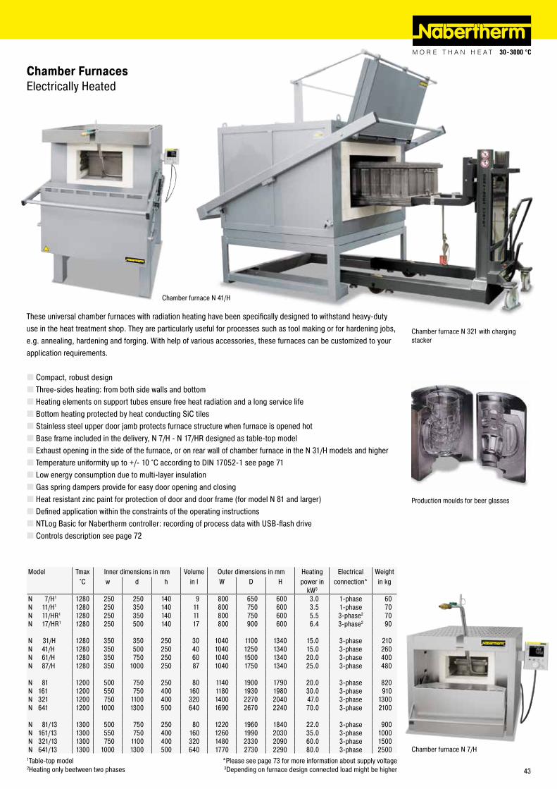
Production moulds for beer glasses
These universal chamber furnaces with radiation heating have been specifically designed to withstand heavy-duty use in the heat treatment shop. They are particularly useful for processes such as tool making or for hardening jobs, e.g. annealing, hardening and forging. With help of various accessories, these furnaces can be customized to your application requirements.
� Compact, robust design � Three-sides heating: from both side walls and bottom � Heating elements on support tubes ensure free heat radiation and a long service life � Bottom heating protected by heat conducting SiC tiles � Stainless steel upper door jamb protects furnace structure when furnace is opened hot � Base frame included in the delivery, N 7/H - N 17/HR designed as table-top model � Exhaust opening in the side of the furnace, or on rear wall of chamber furnace in the N 31/H models and higher � Temperature uniformity up to +/- 10 °C according to DIN 17052-1 see page 71 � Low energy consumption due to multi-layer insulation � Gas spring dampers provide for easy door opening and closing � Heat resistant zinc paint for protection of door and door frame (for model N 81 and larger) � Defined application within the constraints of the operating instructions � NTLog Basic for Nabertherm controller: recording of process data with USB-flash drive � Controls description see page 72
Chamber Furnaces Electrically Heated
Model Tmax Inner dimensions in mm Volume Outer dimensions in mm Heating Electrical Weight°C w d h in l W D H power in
kW3connection* in kg
N 7/H1 1280 250 250 140 9 800 650 600 3.0 1-phase 60N 11/H1 1280 250 350 140 11 800 750 600 3.5 1-phase 70N 11/HR1 1280 250 350 140 11 800 750 600 5.5 3-phase2 70N 17/HR1 1280 250 500 140 17 800 900 600 6.4 3-phase2 90
N 31/H 1280 350 350 250 30 1040 1100 1340 15.0 3-phase 210N 41/H 1280 350 500 250 40 1040 1250 1340 15.0 3-phase 260N 61/H 1280 350 750 250 60 1040 1500 1340 20.0 3-phase 400N 87/H 1280 350 1000 250 87 1040 1750 1340 25.0 3-phase 480
N 81 1200 500 750 250 80 1140 1900 1790 20.0 3-phase 820N 161 1200 550 750 400 160 1180 1930 1980 30.0 3-phase 910N 321 1200 750 1100 400 320 1400 2270 2040 47.0 3-phase 1300N 641 1200 1000 1300 500 640 1690 2670 2240 70.0 3-phase 2100
N 81/13 1300 500 750 250 80 1220 1960 1840 22.0 3-phase 900N 161/13 1300 550 750 400 160 1260 1990 2030 35.0 3-phase 1000N 321/13 1300 750 1100 400 320 1480 2330 2090 60.0 3-phase 1500N 641/13 1300 1000 1300 500 640 1770 2730 2290 80.0 3-phase 2500
1Table-top model *Please see page 73 for more information about supply voltage2Heating only beetween two phases 3Depending on furnace design connected load might be higher
Chamber furnace N 321 with charging stacker
Chamber furnace N 7/H
Chamber furnace N 41/H
43
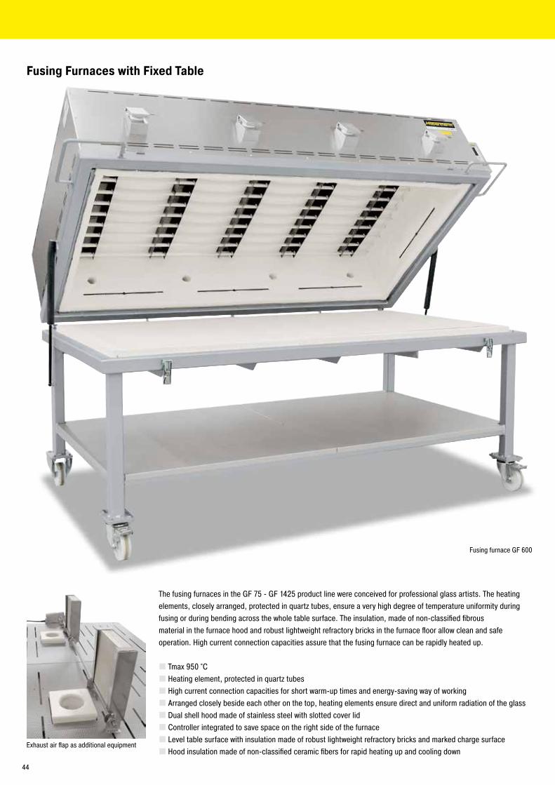
Fusing Furnaces with Fixed Table
The fusing furnaces in the GF 75 - GF 1425 product line were conceived for professional glass artists. The heatingelements, closely arranged, protected in quartz tubes, ensure a very high degree of temperature uniformity duringfusing or during bending across the whole table surface. The insulation, made of non-classified fibrousmaterial in the furnace hood and robust lightweight refractory bricks in the furnace floor allow clean and safeoperation. High current connection capacities assure that the fusing furnace can be rapidly heated up.
� Tmax 950 °C � Heating element, protected in quartz tubes � High current connection capacities for short warm-up times and energy-saving way of working � Arranged closely beside each other on the top, heating elements ensure direct and uniform radiation of the glass � Dual shell hood made of stainless steel with slotted cover lid � Controller integrated to save space on the right side of the furnace � Level table surface with insulation made of robust lightweight refractory bricks and marked charge surface � Hood insulation made of non-classified ceramic fibers for rapid heating up and cooling down
Exhaust air flap as additional equipment
Fusing furnace GF 600
44
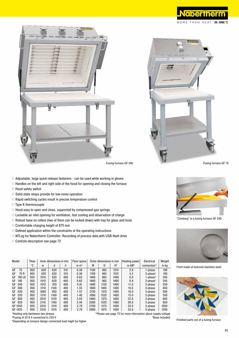
Model Tmax Inner dimensions in mm Floor space Outer dimensions in mm Heating power Electrical Weight°C w d h in m2 W D H3 in kW4 connection* in kg
GF 75 950 620 620 310 0.38 1100 965 1310 3.6 1-phase 180GF 75 R 950 620 620 310 0.38 1100 965 1310 5.5 3-phase1 180GF 190 LE 950 1010 620 400 0.62 1480 965 1400 6.0 1-phase2 245GF 190 950 1010 620 400 0.62 1480 965 1400 6.4 3-phase1 245GF 240 950 1010 810 400 0.81 1480 1155 1400 11.0 3-phase 250GF 380 950 1210 1100 400 1.33 1680 1465 1400 15.0 3-phase 450GF 420 950 1660 950 400 1.57 2130 1315 1400 18.0 3-phase 500GF 520 950 1210 1160 400 1.40 1680 1525 1400 15.0 3-phase 550GF 600 950 2010 1010 400 2.03 2480 1375 1400 22.0 3-phase 600GF 920 950 2110 1160 400 2.44 2580 1525 1400 26.0 3-phase 850GF 1050 950 2310 1210 400 2.79 2780 1575 1400 32.0 3-phase 1050GF 1425 950 2510 1510 400 3.79 2880 1875 1400 32.0 3-phase 12001Heating only beetween two phases *Please see page 73 for more information about supply voltage2Fusing of 32 A if connected to 230 V 3Base included4Depending on furnace design connected load might be higher
� Adjustable, large quick-release fasteners - can be used while working in gloves � Handles on the left and right side of the hood for opening and closing the furnace � Hood safety switch � Solid state relays provide for low-noise operation � Rapid switching cycles result in precise temperature control � Type K thermocouple � Hood easy to open and close, supported by compressed-gas springs � Lockable air inlet opening for ventilation, fast cooling and observation of charge � Robust base on rollers (two of them can be locked down) with tray for glass and tools � Comfortable charging height of 870 mm � Defined application within the constraints of the operating instructions � NTLog for Nabertherm Controller: Recording of process data with USB-flash drive � Controls description see page 72
Finished parts out of a fusing furnace
"Combing" in a fusing furnace GF 240
Front made of textured stainless steel
Fusing furnace GF 240 Fusing furnace GF 75
45
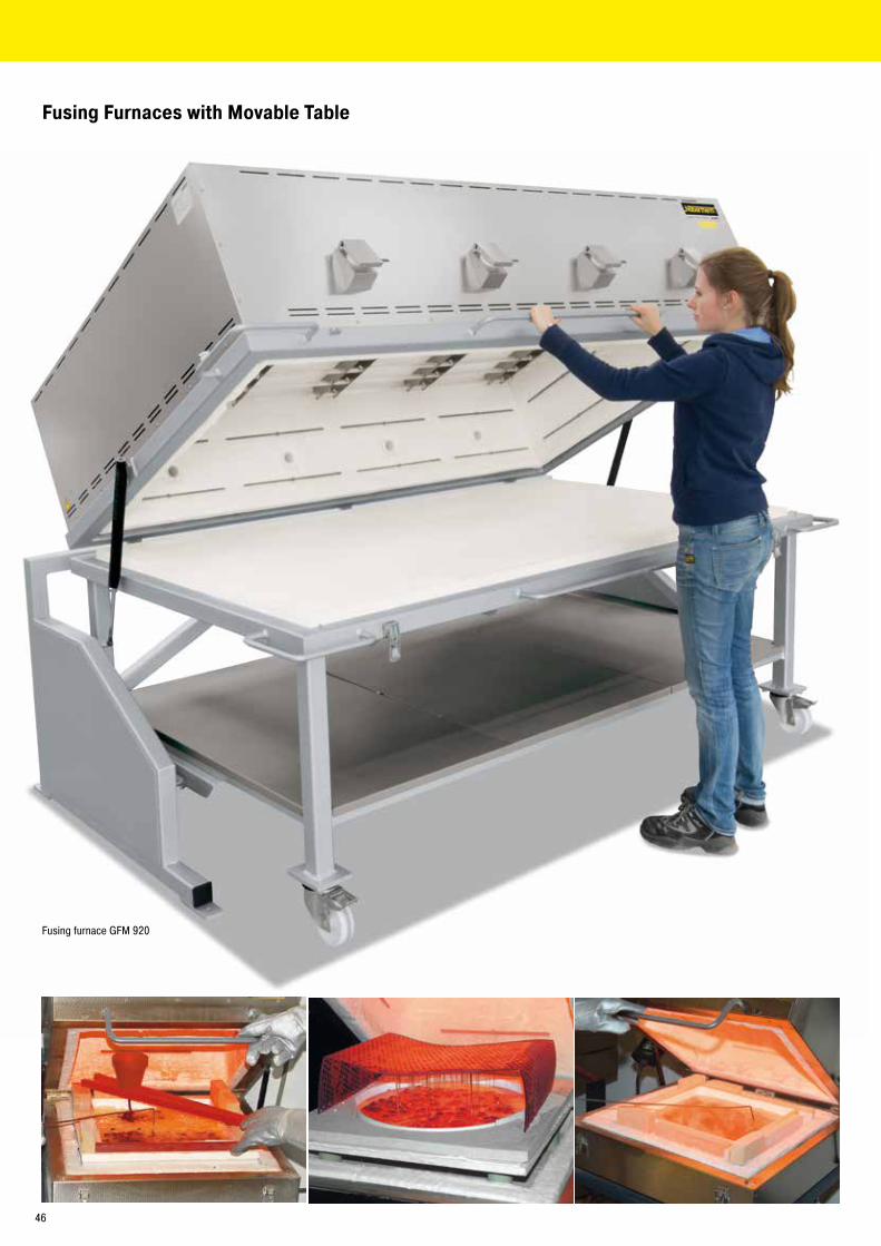
Fusing Furnaces with Movable Table
Fusing furnace GFM 920
46
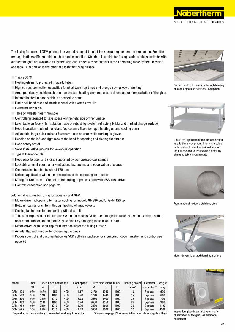
Model Tmax Inner dimensions in mm Floor space Outer dimensions in mm Heating power Electrical Weight°C w d h in m2 W D H in kW1 connection* in kg
GFM 420 950 1660 950 400 1.57 2170 1340 1400 18 3-phase 630GFM 520 950 1210 1160 400 1.40 1720 1440 1400 15 3-phase 660GFM 600 950 2010 1010 400 2.03 2530 1400 1400 22 3-phase 730GFM 920 950 2110 1160 400 2.44 2630 1550 1400 26 3-phase 980GFM 1050 950 2310 1210 400 2.79 2830 1600 1400 32 3-phase 1190GFM 1425 950 2510 1510 400 3.79 3030 1900 1400 32 3-phase 13901Depending on furnace design connected load might be higher *Please see page 73 for more information about supply voltage
Motor-driven lid as additional equipment
Inspection glass in air inlet opening for observation of the glass as additional equipment
The fusing furnaces of GFM product line were developed to meet the special requirements of production. For diffe-rent applications different table models can be supplied. Standard is a table for fusing. Various tables and tubs with different heights are available as system add-ons. Especially economical is the alternating table system, in which one table is loaded while the other one is in the fusing furnace.
� Tmax 950 °C � Heating element, protected in quartz tubes � High current connection capacities for short warm-up times and energy-saving way of working � Arranged closely beside each other on the top, heating elements ensure direct and uniform radiation of the glass � Infrared heated in hood which is attached to stand � Dual shell hood made of stainless steel with slotted cover lid � Delivered with table � Table on wheels, freely movable � Controller integrated to save space on the right side of the furnace � Level table surface with insulation made of robust lightweight refractory bricks and marked charge surface � Hood insulation made of non-classified ceramic fibers for rapid heating up and cooling down � Adjustable, large quick-release fasteners - can be used while working in gloves � Handles on the left and right side of the hood for opening and closing the furnace � Hood safety switch � Solid state relays provide for low-noise operation � Type K thermocouple � Hood easy to open and close, supported by compressed-gas springs � Lockable air inlet opening for ventilation, fast cooling and observation of charge � Comfortable charging height of 870 mm � Defined application within the constraints of the operating instructions � NTLog for Nabertherm Controller: Recording of process data with USB-flash drive � Controls description see page 72
Additional features for fusing furnaces GF and GFM � Motor-driven lid opening for faster cooling for models GF 380 and/or GFM 420 up � Bottom heating for uniform through heating of large objects � Cooling fan for accelerated cooling with closed lid � Tables for expansion of the furnace system for models GFM; Interchangeable table system to use the residual heat of the furnace and to reduce cycle times by changing table in warm state. � Motor-driven exhaust air flap for faster cooling of the fusing furnace � Air inlet flap with window for observing the glass � Process control and documentation via VCD software package for monitoring, documentation and control see page 75
Tables for expansion of the furnace system as additional equipment; Interchangeable table system to use the residual heat of the furnace and to reduce cycle times by changing table in warm state
Bottom heating for uniform through heating of large objects as additional equipment
Front made of textured stainless steel
47

Tub Furnaces with Wire Heating
Bottom heating covered by SiC tiles to create level stacking support
For slumping and bending of complex glass parts, e.g. glass furniture, shower cabins, etc., tub furnaces are the right choice. Full coverage heating: from the lid, all 4 sides and the tub bottom. Due to the modular system additio-nal tubs in customized dimensions can be provided.
� Tmax 900 °C � Full coverage heating: from lid, all 4 sides and bottom � 3-zone temperature control from top to bottom for optimal temperature uniformity � Heating elements mounted on ceramic support tubes for free heat radiation and long service life � Bottom heating covered by SiC tiles � Hood insulated with non-classified fiber materials
� Tub bottom insulated with multi-layer of insulation, lightweight refractory bricks on the hot face � Hinged hood as standard version � Gas operated dampers provide for easy hood opening � Manually operated exhaust air flaps � Tub on wheels can be pulled out manually � Rails on floor for perfect tub guidance included � Defined application within the constraints of the operating instructions � Controls description see page 72
Additional equipment � Interchangeable table system on rails, electrically driven on request � Electro-hydraulically driven hood instead of hinged cover � Tub insert to elevate bottom height, in order to use the furnace for glass fusing applications (in this product version the tub heating can be switched off
Tub furnace GW 1660
Tub furnace GW 2200
48
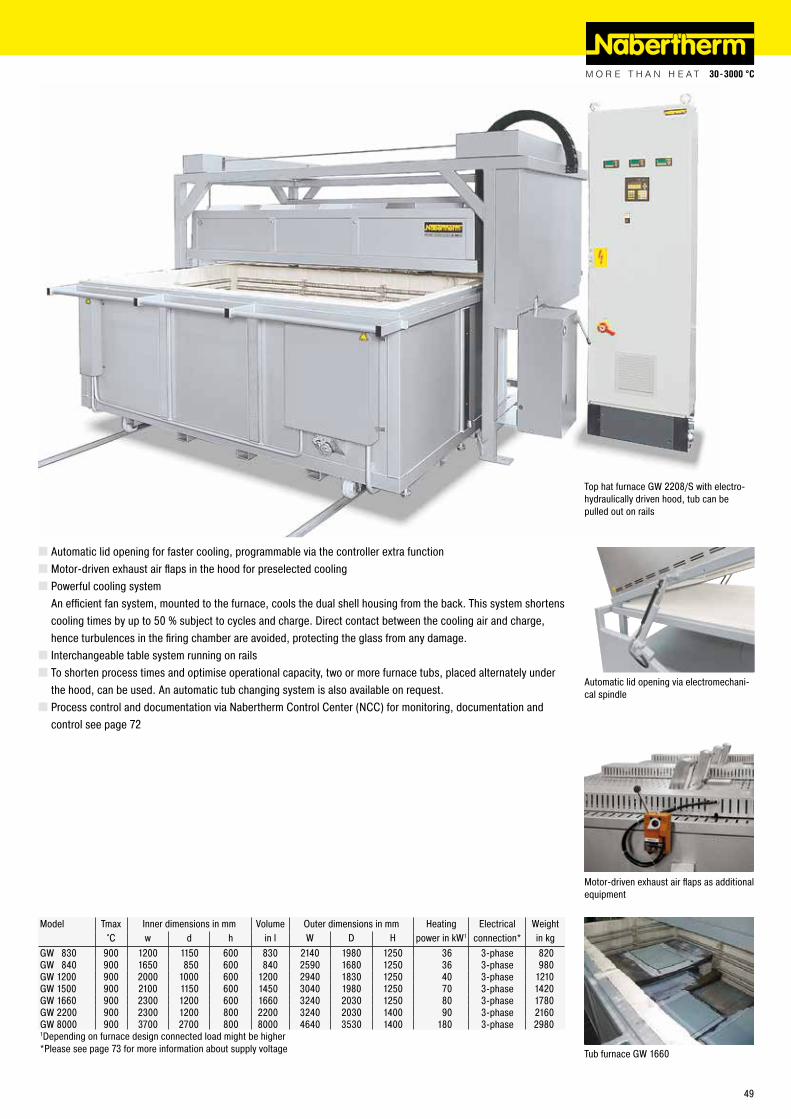
Model Tmax Inner dimensions in mm Volume Outer dimensions in mm Heating Electrical Weight°C w d h in l W D H power in kW1 connection* in kg
GW 830 900 1200 1150 600 830 2140 1980 1250 36 3-phase 820GW 840 900 1650 850 600 840 2590 1680 1250 36 3-phase 980GW 1200 900 2000 1000 600 1200 2940 1830 1250 40 3-phase 1210GW 1500 900 2100 1150 600 1450 3040 1980 1250 70 3-phase 1420GW 1660 900 2300 1200 600 1660 3240 2030 1250 80 3-phase 1780GW 2200 900 2300 1200 800 2200 3240 2030 1400 90 3-phase 2160GW 8000 900 3700 2700 800 8000 4640 3530 1400 180 3-phase 29801Depending on furnace design connected load might be higher *Please see page 73 for more information about supply voltage
Automatic lid opening via electromechani-cal spindle
Top hat furnace GW 2208/S with electro-hydraulically driven hood, tub can be pulled out on rails
� Automatic lid opening for faster cooling, programmable via the controller extra function � Motor-driven exhaust air flaps in the hood for preselected cooling � Powerful cooling systemAn efficient fan system, mounted to the furnace, cools the dual shell housing from the back. This system shortens cooling times by up to 50 % subject to cycles and charge. Direct contact between the cooling air and charge, hence turbulences in the firing chamber are avoided, protecting the glass from any damage. � Interchangeable table system running on rails � To shorten process times and optimise operational capacity, two or more furnace tubs, placed alternately under the hood, can be used. An automatic tub changing system is also available on request. � Process control and documentation via Nabertherm Control Center (NCC) for monitoring, documentation and control see page 72
Motor-driven exhaust air flaps as additional equipment
Tub furnace GW 1660
49
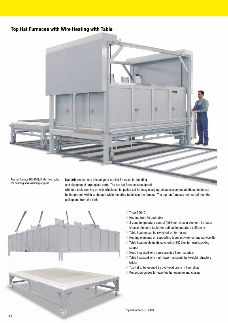
Top Hat Furnaces with Wire Heating with Table
Nabertherm markets this range of top hat furnaces for bending and slumping of large glass parts. The top hat furnace is equipped with one table running on rails which can be pulled out for easy charging. As accessory an additional table can be integrated, which is charged while the other table is in the furnace. The top hat furnaces are heated from the ceiling and from the table.
Top hat furnace HG 5208/S with two tables for bending and slumping of glass
Top hat furnace HG 2000
� Tmax 900 °C � Heating from lid and table � 3-zone temperature control (lid-inner circular element, lid-outer circular element, table) for optimal temperature uniformity � Table heating can be switched-off for fusing � Heating elements on supporting tubes provide for long service life � Table heating elements covered by SiC tiles for level stacking support � Hood insulated with non-classified fiber materials � Table insulated with multi-layer resistant, lightweight refractory bricks � Top hat to be opened by overhead crane in floor shop � Protection guides for easy top hat opening and closing
50
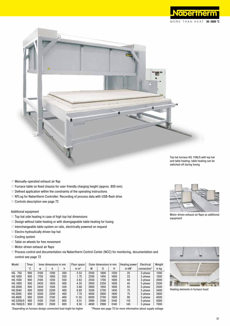
Model Tmax Inner dimensions in mm Floor space Outer dimensions in mm Heating power Electrical Weight°C w d h in m2 W D H in kW1 connection* in kg
HG 750 900 2100 1200 300 2.52 2550 1800 1350 35 3-phase 1200HG 1000 900 1750 1000 550 1.75 2200 1450 1600 33 3-phase 1500HG 1500 900 2100 1250 550 2.63 2550 1700 1600 44 3-phase 2000HG 1800 900 2450 1850 400 4.35 2950 2350 1600 45 3-phase 2500HG 2000 900 2450 1500 550 3.68 2900 1950 1600 55 3-phase 2500HG 2640 900 3000 2200 400 6.60 3500 2700 1450 75 3-phase 3400HG 3000 900 3500 2200 400 7.70 4000 2800 1600 75 3-phase 3800HG 4800 900 5500 2100 400 11.55 6000 2700 1600 90 3-phase 4500HG 5208/S 900 3100 2100 800 6.51 3990 2590 3140 110 3-phase 5000HG 7608/S 900 3800 2500 800 9.50 4690 2990 3140 143 3-phase 70001Depending on furnace design connected load might be higher *Please see page 73 for more information about supply voltage
Top hat furnace HG 1196/S with top hat and table heating; table heating can be switched-off during fusing
� Manually-operated exhaust air flap � Furnace table on fixed chassis for user-friendly charging height (approx. 800 mm) � Defined application within the constraints of the operating instructions � NTLog for Nabertherm Controller: Recording of process data with USB-flash drive � Controls description see page 72
Additional equipment � Top hat side heating in case of high top hat dimensions � Design without table heating or with disengageable table heating for fusing � Interchangeable table system on rails, electrically powered on request � Electro-hydraulically driven top hat � Cooling system � Table on wheels for free movement � Motor-driven exhaust air flaps � Process control and documentation via Nabertherm Control Center (NCC) for monitoring, documentation and control see page 72
Heating elements in furnace hood
Motor-driven exhaust air flaps as additional equipment
51
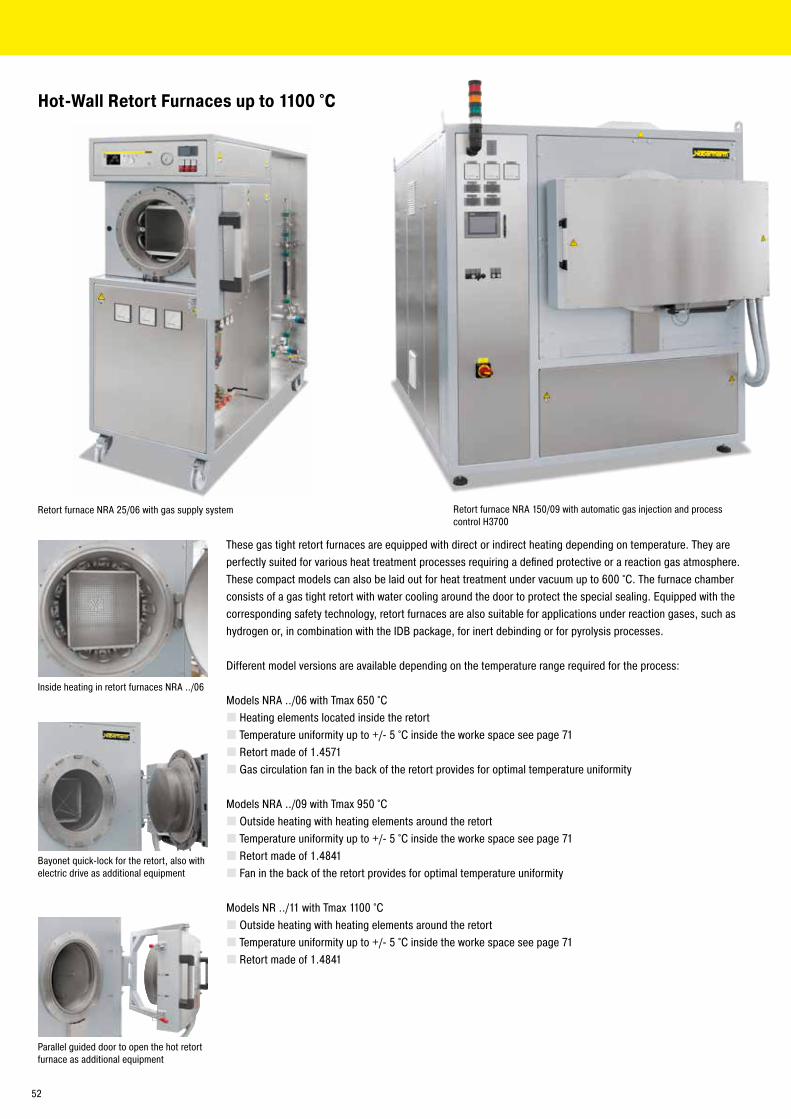
Retort furnace NRA 150/09 with automatic gas injection and process control H3700
These gas tight retort furnaces are equipped with direct or indirect heating depending on temperature. They are perfectly suited for various heat treatment processes requiring a defined protective or a reaction gas atmosphere. These compact models can also be laid out for heat treatment under vacuum up to 600 °C. The furnace chamber consists of a gas tight retort with water cooling around the door to protect the special sealing. Equipped with the corresponding safety technology, retort furnaces are also suitable for applications under reaction gases, such as hydrogen or, in combination with the IDB package, for inert debinding or for pyrolysis processes.
Different model versions are available depending on the temperature range required for the process:
Models NRA ../06 with Tmax 650 °C � Heating elements located inside the retort � Temperature uniformity up to +/- 5 °C inside the worke space see page 71 � Retort made of 1.4571 � Gas circulation fan in the back of the retort provides for optimal temperature uniformity
Models NRA ../09 with Tmax 950 °C � Outside heating with heating elements around the retort � Temperature uniformity up to +/- 5 °C inside the worke space see page 71 � Retort made of 1.4841 � Fan in the back of the retort provides for optimal temperature uniformity
Models NR ../11 with Tmax 1100 °C � Outside heating with heating elements around the retort � Temperature uniformity up to +/- 5 °C inside the worke space see page 71 � Retort made of 1.4841
Hot-Wall Retort Furnaces up to 1100 °C
Inside heating in retort furnaces NRA ../06
Retort furnace NRA 25/06 with gas supply system
Bayonet quick-lock for the retort, also with electric drive as additional equipment
Parallel guided door to open the hot retort furnace as additional equipment
52

Vacuum pump for cold evacuation of the retort
Process control H3700 for automatic version
Basic version � Compact housing in frame design with removable stainless steel sheets � Controls and gas supply integrated in the furnace housing �Welded charging supports in the retort or air-baffle box in the furnace with atmosphere circulation � Swivel door hinged on right side with open cooling water system � Depending on furnace volume for 950 °C- and 1100 °C-version the control system is divided in one or more heating zones � Temperature control as furnace control with temperature measurement outside the retort � Gas supply system for one non-flammable protective or reaction gas with flow meter and manual valve � Port for vacuum pump for cold evacuation � Operation under vacuum up to 600 °C with optional single-stage rotary vane pump � Defined application within the constraints of the operating instructions � NTLog Basic for Nabertherm controller: recording of process data with USB-flash drive � Controls description see page 72
Additional equipment � Upgrade for other non-flammable gases � Automatic gas injection, including MFC flow controller for alternating volume flow, controlled with process control H3700, H1700 � Vacuum pump for evacuating of the retort up to 600 °C, attainable vacuum up to 10-5 mbar subject to selected pump � Cooling system for shortening process times � Heat exchanger with closed-loop cooling water circuit for door cooling � Measuring device for residual oxygen content � Door heating � Temperature control as charge control with temperature measurement inside and outside the retort � Gas inlet with solenoid valve, controlled by the program � Process control and documentation via VCD software package or Nabertherm Control Center (NCC) for monitoring, documentation and control see page 72
Retort furnace NRA 25/09
Retort furnace NRA 50/09 H2
53
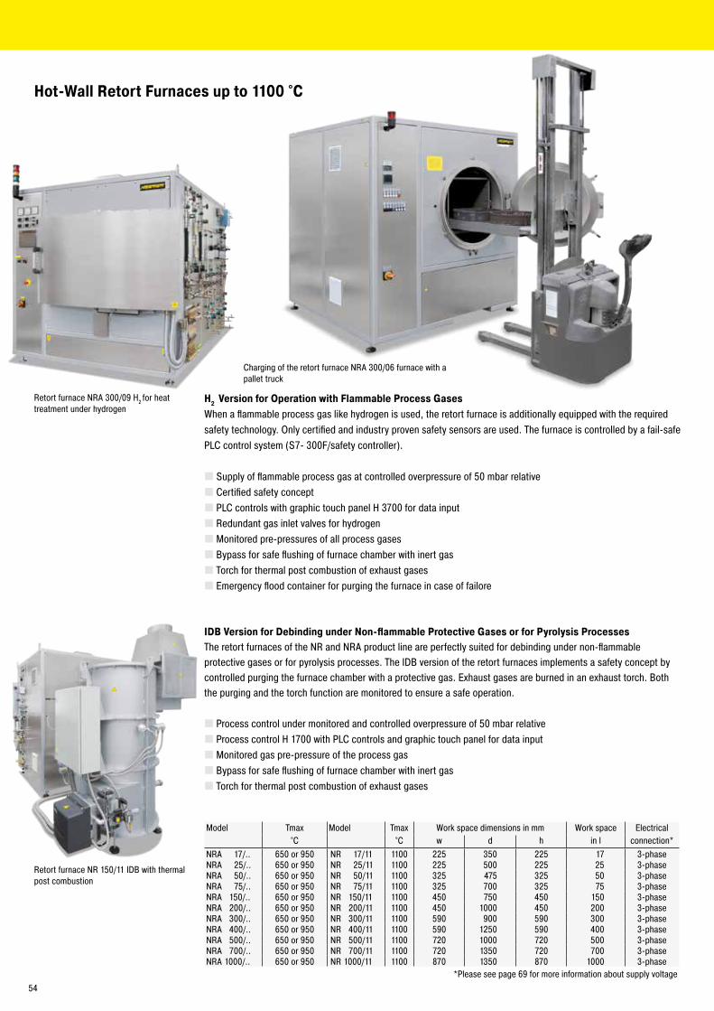
Retort furnace NRA 300/09 H2 for heat treatment under hydrogen
H2 Version for Operation with Flammable Process GasesWhen a flammable process gas like hydrogen is used, the retort furnace is additionally equipped with the required safety technology. Only certified and industry proven safety sensors are used. The furnace is controlled by a fail-safe PLC control system (S7- 300F/safety controller).
� Supply of flammable process gas at controlled overpressure of 50 mbar relative � Certified safety concept � PLC controls with graphic touch panel H 3700 for data input � Redundant gas inlet valves for hydrogen � Monitored pre-pressures of all process gases � Bypass for safe flushing of furnace chamber with inert gas � Torch for thermal post combustion of exhaust gases � Emergency flood container for purging the furnace in case of failore
Charging of the retort furnace NRA 300/06 furnace with a pallet truck
IDB Version for Debinding under Non-flammable Protective Gases or for Pyrolysis ProcessesThe retort furnaces of the NR and NRA product line are perfectly suited for debinding under non-flammable protective gases or for pyrolysis processes. The IDB version of the retort furnaces implements a safety concept by controlled purging the furnace chamber with a protective gas. Exhaust gases are burned in an exhaust torch. Both the purging and the torch function are monitored to ensure a safe operation.
� Process control under monitored and controlled overpressure of 50 mbar relative � Process control H 1700 with PLC controls and graphic touch panel for data input � Monitored gas pre-pressure of the process gas � Bypass for safe flushing of furnace chamber with inert gas � Torch for thermal post combustion of exhaust gases
Retort furnace NR 150/11 IDB with thermal post combustion
Model Tmax Model Tmax Work space dimensions in mm Work space Electrical°C °C w d h in l connection*
NRA 17/.. 650 or 950 NR 17/11 1100 225 350 225 17 3-phaseNRA 25/.. 650 or 950 NR 25/11 1100 225 500 225 25 3-phaseNRA 50/.. 650 or 950 NR 50/11 1100 325 475 325 50 3-phaseNRA 75/.. 650 or 950 NR 75/11 1100 325 700 325 75 3-phaseNRA 150/.. 650 or 950 NR 150/11 1100 450 750 450 150 3-phaseNRA 200/.. 650 or 950 NR 200/11 1100 450 1000 450 200 3-phaseNRA 300/.. 650 or 950 NR 300/11 1100 590 900 590 300 3-phaseNRA 400/.. 650 or 950 NR 400/11 1100 590 1250 590 400 3-phaseNRA 500/.. 650 or 950 NR 500/11 1100 720 1000 720 500 3-phaseNRA 700/.. 650 or 950 NR 700/11 1100 720 1350 720 700 3-phaseNRA 1000/.. 650 or 950 NR 1000/11 1100 870 1350 870 1000 3-phase
*Please see page 69 for more information about supply voltage
Hot-Wall Retort Furnaces up to 1100 °C
54
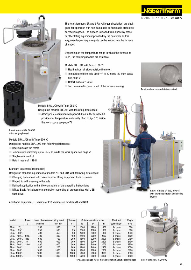
The retort furnaces SR and SRA (with gas circulation) are desi-gned for operation with non-flammable or flammable protective or reaction gases. The furnace is loaded from above by crane or other lifting equipment provided by the customer. In this way, even large charge weights can be loaded into the furnace chamber.
Depending on the temperature range in which the furnace be used, the following models are available:
Models SR .../11 with Tmax 1100 °C � Heating from all sides outside the retort � Temperature uniformity up to +/- 5 °C inside the work space see page 71 � Retort made of 1.4841 � Top down multi-zone control of the furnace heating
Retort furnace SR 170/1000/11 with changeable retort and cooling station
Model Tmax Inner dimensions of alloy retort Volume Outer dimensions in mm Electrical Weight°C Ø in mm h in mm in l W D H connection* in kg
SR(A) 17/.. 250 350 17 1300 1700 1800 3-phase 600SR(A) 25/.. 250 500 25 1300 1900 1800 3-phase 800SR(A) 50/.. 400 450 50 1400 2000 1800 3-phase 1300SR(A) 100/.. 600, 400 800 100 1400 2000 2100 3-phase 1500SR(A) 200/.. 950 600 700 200 1600 2200 2200 3-phase 2100SR(A) 300/.. or 600 1000 300 1600 2200 2500 3-phase 2400SR(A) 500/.. 1100 800 1000 500 1800 2400 2700 3-phase 2800SR(A) 600/.. 800 1200 600 1800 2400 2900 3-phase 3000SR(A) 800/.. 1000 1000 800 2000 2600 2800 3-phase 3100SR(A) 1000/.. 1000 1300 1000 2000 2600 3100 3-phase 3300SR(A) 1500/.. 1200 1300 1500 2200 2800 3300 3-phase 3500
*Please see page 73 for more information about supply voltage
Retort furnace SRA 300/06 with charging basket
Models SRA ../09 with Tmax 950 °CDesign like models SR…/11 with following differences:
� Atmosphere circulation with powerful fan in the furnace lid provides for temperature uniformity of up to +/- 5 °C inside the work space see page 71
Models SRA ../06 with Tmax 600 °CDesign like models SRA…/09 with following differences:
� Heating inside the retort � Temperature uniformity up to +/- 5 °C inside the work space see page 71 � Single-zone control � Retort made of 1.4841
Standard Equipment (all models)Design like standard equipment of models NR and NRA with following differences:
� Charging from above with crane or other lifting equipment from customer � Hinged lid with opening to the side � Defined application within the constraints of the operating instructions � NTLog Basic for Nabertherm controller: recording of process data with USB-flash drive
Additional equipment, H2 version or IDB version see models NR and NRA
Front made of textured stainless steel
Retort furnace SRA 200/09
55
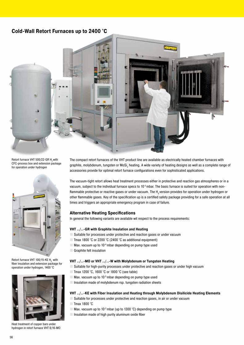
The compact retort furnaces of the VHT product line are available as electrically heated chamber furnaces with graphite, molybdenum, tungsten or MoSi2 heating. A wide variety of heating designs as well as a complete range of accessories provide for optimal retort furnace configurations even for sophisticated applications.
The vacuum-tight retort allows heat treatment processes either in protective and reaction gas atmospheres or in a vacuum, subject to the individual furnace specs to 10-5 mbar. The basic furnace is suited for operation with non-flammable protective or reactive gases or under vacuum. The H2 version provides for operation under hydrogen or other flammable gases. Key of the specification up is a certified safety package providing for a safe operation at all times and triggers an appropriate emergency program in case of failure.
Alternative Heating SpecificationsIn general the following variants are available wit respect to the process requirements:
VHT ../..-GR with Graphite Insulation and Heating � Suitable for processes under protective and reaction gases or under vacuum � Tmax 1800 °C or 2200 °C (2400 °C as additional equipment) � Max. vacuum up to 10-4 mbar depending on pump type used � Graphite felt insulation
VHT ../..-MO or VHT ../..-W with Molybdenum or Tungsten Heating � Suitable for high-purity processes under protective and reaction gases or under high vacuum � Tmax 1200 °C, 1600 °C or 1800 °C (see table) � Max. vacuum up to 10-5 mbar depending on pump type used � Insulation made of molybdenum rsp. tungsten radiation sheets
VHT ../..-KE with Fiber Insulation and Heating through Molybdenum Disilicide Heating Elements � Suitable for processes under protective and reaction gases, in air or under vacuum � Tmax 1800 °C � Max. vacuum up to 10-2 mbar (up to 1300 °C) depending on pump type � Insulation made of high purity aluminum oxide fiber
Cold-Wall Retort Furnaces up to 2400 °C
Retort furnace VHT 100/15-KE H2 with fiber insulation and extension package for operation under hydrogen, 1400 °C
Retort furnace VHT 500/22-GR H2 with CFC-process box and extension package for operation under hydrogen
Heat treatment of copper bars under hydrogen in retort furnace VHT 8/16-MO
56
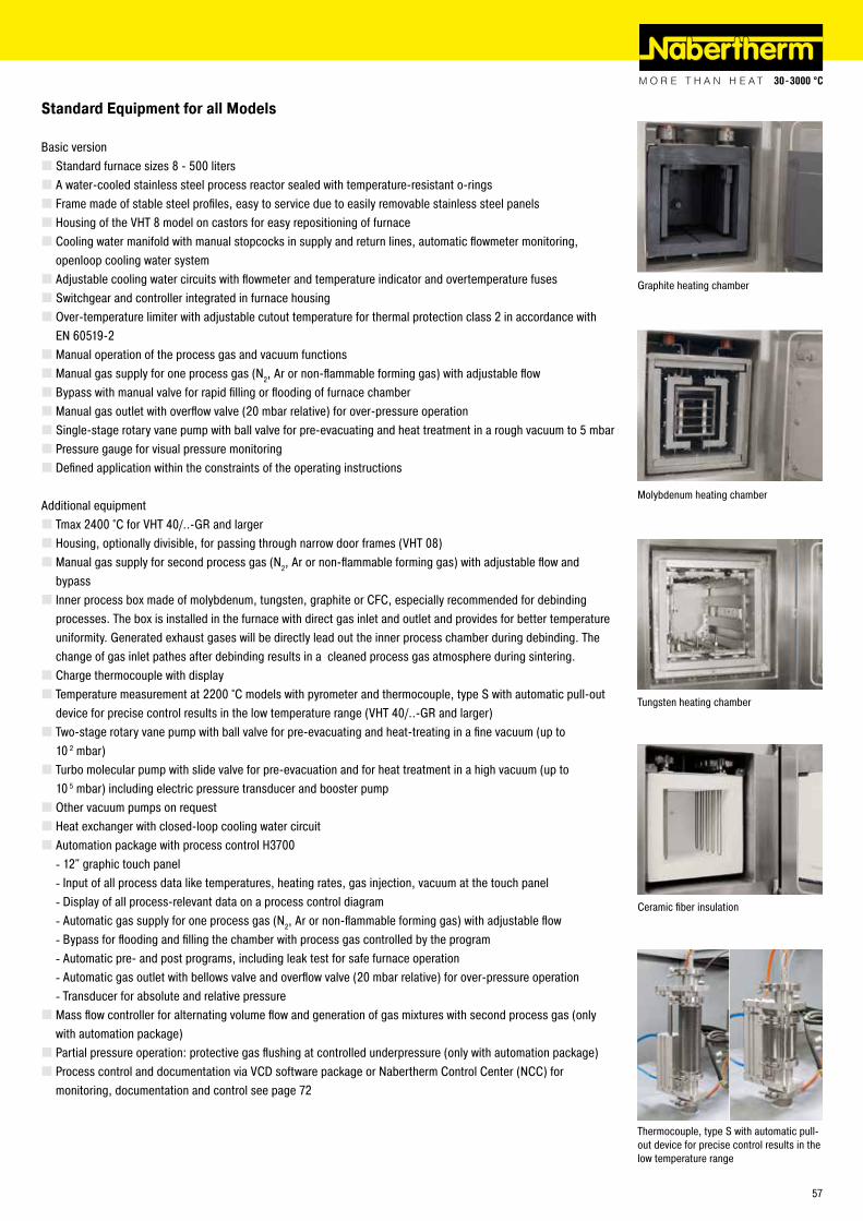
Graphite heating chamber
Ceramic fiber insulation
Molybdenum heating chamber
Standard Equipment for all Models
Basic version � Standard furnace sizes 8 - 500 liters � A water-cooled stainless steel process reactor sealed with temperature-resistant o-rings � Frame made of stable steel profiles, easy to service due to easily removable stainless steel panels � Housing of the VHT 8 model on castors for easy repositioning of furnace � Cooling water manifold with manual stopcocks in supply and return lines, automatic flowmeter monitoring, openloop cooling water system � Adjustable cooling water circuits with flowmeter and temperature indicator and overtemperature fuses � Switchgear and controller integrated in furnace housing � Over-temperature limiter with adjustable cutout temperature for thermal protection class 2 in accordance with EN 60519-2 � Manual operation of the process gas and vacuum functions � Manual gas supply for one process gas (N2, Ar or non-flammable forming gas) with adjustable flow � Bypass with manual valve for rapid filling or flooding of furnace chamber � Manual gas outlet with overflow valve (20 mbar relative) for over-pressure operation � Single-stage rotary vane pump with ball valve for pre-evacuating and heat treatment in a rough vacuum to 5 mbar � Pressure gauge for visual pressure monitoring � Defined application within the constraints of the operating instructions
Additional equipment � Tmax 2400 °C for VHT 40/..-GR and larger � Housing, optionally divisible, for passing through narrow door frames (VHT 08) � Manual gas supply for second process gas (N2, Ar or non-flammable forming gas) with adjustable flow and bypass � Inner process box made of molybdenum, tungsten, graphite or CFC, especially recommended for debinding processes. The box is installed in the furnace with direct gas inlet and outlet and provides for better temperature uniformity. Generated exhaust gases will be directly lead out the inner process chamber during debinding. The change of gas inlet pathes after debinding results in a cleaned process gas atmosphere during sintering. � Charge thermocouple with display � Temperature measurement at 2200 °C models with pyrometer and thermocouple, type S with automatic pull-out device for precise control results in the low temperature range (VHT 40/..-GR and larger) � Two-stage rotary vane pump with ball valve for pre-evacuating and heat-treating in a fine vacuum (up to 10 2 mbar) � Turbo molecular pump with slide valve for pre-evacuation and for heat treatment in a high vacuum (up to 10 5 mbar) including electric pressure transducer and booster pump � Other vacuum pumps on request � Heat exchanger with closed-loop cooling water circuit � Automation package with process control H3700
- 12" graphic touch panel - Input of all process data like temperatures, heating rates, gas injection, vacuum at the touch panel - Display of all process-relevant data on a process control diagram - Automatic gas supply for one process gas (N2, Ar or non-flammable forming gas) with adjustable flow - Bypass for flooding and filling the chamber with process gas controlled by the program - Automatic pre- and post programs, including leak test for safe furnace operation - Automatic gas outlet with bellows valve and overflow valve (20 mbar relative) for over-pressure operation - Transducer for absolute and relative pressure
� Mass flow controller for alternating volume flow and generation of gas mixtures with second process gas (only with automation package) � Partial pressure operation: protective gas flushing at controlled underpressure (only with automation package) � Process control and documentation via VCD software package or Nabertherm Control Center (NCC) for monitoring, documentation and control see page 72
Thermocouple, type S with automatic pull-out device for precise control results in the low temperature range
Tungsten heating chamber
57
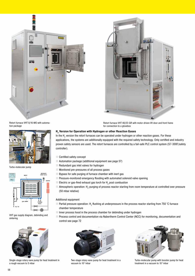
VHT gas supply diagram, debinding and sintering
H2 Version for Operation with Hydrogen or other Reaction GasesIn the H2 version the retort furnaces can be operated under hydrogen or other reaction gases. For these applications, the systems are additionally equipped with the required safety technology. Only certified and industry proven safety sensors are used. The retort furnaces are controlled by a fail-safe PLC control system (S7-300F/safety controller).
� Certified safety concept � Automation package (additional equipment see page 57) � Redundant gas inlet valves for hydrogen � Monitored pre-pressures of all process gases � Bypass for safe purging of furnace chamber with inert gas � Pressure-monitored emergency flooding with automated solenoid valve opening � Electric or gas-fired exhaust gas torch for H2 post combustion � Atmospheric operation: H2-purging of process reactor starting from room temperature at controlled over pressure (50 mbar relative)
Additional equipment � Partial pressure operation: H2 flushing at underpressure in the process reactor starting from 750 °C furnace chamber temperature � Inner process hood in the process chamber for debinding under hydrogen � Process control and documentation via Nabertherm Control Center (NCC) for monitoring, documentation and control see page 72
Single-stage rotary vane pump for heat treatment in a rough vacuum to 5 mbar
Two-stage rotary vane pump for heat treatment in a vacuum to 10-2 mbar
Turbo-molecular pump with booster pump for heat treatment in a vacuum to 10-5 mbar
Turbo-molecular pump
Retort furnace VHT 8/16-MO with automa-tion package
Retort furnace VHT 40/22-GR with motor-driven lift door and front frame for connection to a glovebox
58
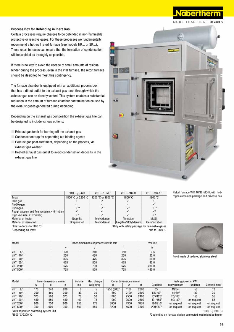
Retort furnace VHT 40/16-MO H2 with hyd-rogen extension package and process box
Process Box for Debinding in Inert GasCertain processes require charges to be debinded in non-flammable protective or reactive gases. For these processes we fundamentally recommend a hot-wall retort furnace (see models NR… or SR…). These retort furnaces can ensure that the formation of condensation will be avoided as throughly as possible.
If there is no way to avoid the escape of small amounts of residual binder during the process, even in the VHT furnace, the retort furnace should be designed to meet this contingency.
The furnace chamber is equipped with an additional process box that has a direct outlet to the exhaust gas torch through which the exhaust gas can be directly vented. This system enables a substantial reduction in the amount of furnace chamber contamination caused by the exhaust gases generated during debinding.
Depending on the exhaust gas composition the exhaust gas line can be designed to include various options.
� Exhaust gas torch for burning off the exhaust gas � Condensation trap for separating out binding agents � Exhaust gas post-treatment, depending on the process, via exhaust gas washer � Heated exhaust gas outlet to avoid condensation deposits in the exhaust gas line
VHT .../..-GR VHT .../..-MO VHT .../18-W VHT .../18-KETmax 1800 °C or 2200 °C 1200 °C or 1600 °C 1800 °C 1800 °CInert gas Air/Oxygen - - - Hydrogen 3,4 3 3 1,3
Rough vacuum and fine vacuum (>10-3 mbar) ²High vacuum (<10-3 mbar) 4 ²Material of heater Graphite Molybdenum Tungsten MoSi2Material of insulation Graphite felt Molybdenum Tungsten/Molybdenum Ceramic fiber1Tmax reduces to 1400 °C 3Only with safety package for flammable gases2Depending on Tmax 4Up to 1800 °C
Model Inner dimensions in mm Volume Max. charge Outer dimensions in mm Heating power in kW4
w d h in l weight/kg W D H Graphite Molybdenum Tungsten Ceramic fiberVHT 8/.. 170 240 200 8 5 1250 (800)1 1100 2000 27 19/343 50 12VHT 40/.. 300 450 300 40 30 1600 2100 2300 83/1032 54/603 130 30VHT 70/.. 375 500 375 70 50 1700 2500 2400 105/1252 70/1003 150 55VHT 100/.. 450 550 450 100 75 1900 2600 2500 131/1552 90/1403 on request 85VHT 250/.. 600 750 600 250 175 30001 4300 3100 180/2102 on request on request on requestVHT 500/.. 750 900 750 500 350 32001 4500 3300 220/2602 on request on request on request1With separated switching system unit 31200 °C/1600 °C21800 °C/2200 °C 4Depending on furnace design connected load might be higher
Model Inner dimensions of process box in mm Volumew d h in l
VHT 8/.. 120 210 150 3,5VHT 40/.. 250 430 250 25,0VHT 70/.. 325 475 325 50,0VHT 100/.. 425 500 425 90,0VHT 250/.. 575 700 575 230,0VHT 500/.. 725 850 725 445,0
Front made of textured stainless steel
59
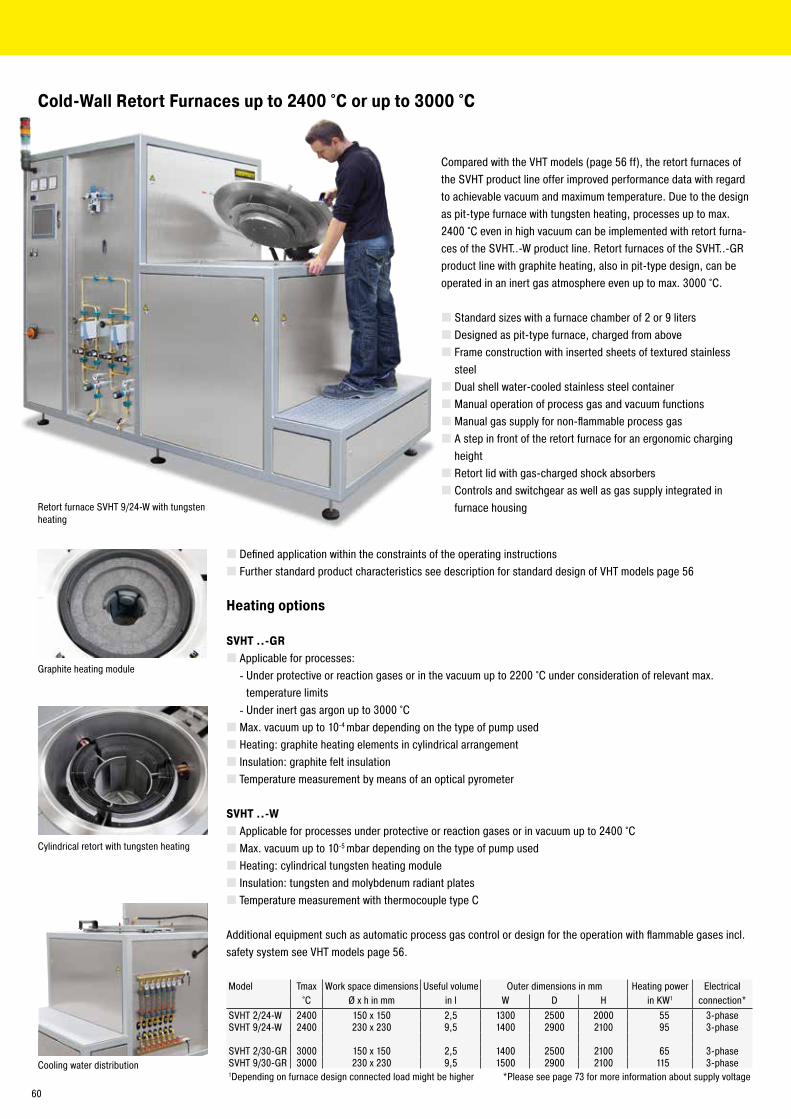
Cold-Wall Retort Furnaces up to 2400 °C or up to 3000 °C
Compared with the VHT models (page 56 ff), the retort furnaces of the SVHT product line offer improved performance data with regard to achievable vacuum and maximum temperature. Due to the design as pit-type furnace with tungsten heating, processes up to max. 2400 °C even in high vacuum can be implemented with retort furna-ces of the SVHT..-W product line. Retort furnaces of the SVHT..-GR product line with graphite heating, also in pit-type design, can be operated in an inert gas atmosphere even up to max. 3000 °C.
� Standard sizes with a furnace chamber of 2 or 9 liters � Designed as pit-type furnace, charged from above � Frame construction with inserted sheets of textured stainless steel � Dual shell water-cooled stainless steel container � Manual operation of process gas and vacuum functions � Manual gas supply for non-flammable process gas � A step in front of the retort furnace for an ergonomic charging height � Retort lid with gas-charged shock absorbers � Controls and switchgear as well as gas supply integrated in furnace housingRetort furnace SVHT 9/24-W with tungsten
heating
Cylindrical retort with tungsten heating
Graphite heating module
Cooling water distribution
� Defined application within the constraints of the operating instructions � Further standard product characteristics see description for standard design of VHT models page 56
Heating options
SVHT ..-GR � Applicable for processes:
- Under protective or reaction gases or in the vacuum up to 2200 °C under consideration of relevant max. temperature limits - Under inert gas argon up to 3000 °C
� Max. vacuum up to 10-4 mbar depending on the type of pump used � Heating: graphite heating elements in cylindrical arrangement � Insulation: graphite felt insulation � Temperature measurement by means of an optical pyrometer
SVHT ..-W � Applicable for processes under protective or reaction gases or in vacuum up to 2400 °C � Max. vacuum up to 10-5 mbar depending on the type of pump used � Heating: cylindrical tungsten heating module � Insulation: tungsten and molybdenum radiant plates � Temperature measurement with thermocouple type C
Additional equipment such as automatic process gas control or design for the operation with flammable gases incl. safety system see VHT models page 56.
Model Tmax Work space dimensions Useful volume Outer dimensions in mm Heating power Electrical°C Ø x h in mm in l W D H in KW1 connection*
SVHT 2/24-W 2400 150 x 150 2,5 1300 2500 2000 55 3-phaseSVHT 9/24-W 2400 230 x 230 9,5 1400 2900 2100 95 3-phase
SVHT 2/30-GR 3000 150 x 150 2,5 1400 2500 2100 65 3-phaseSVHT 9/30-GR 3000 230 x 230 9,5 1500 2900 2100 115 3-phase1Depending on furnace design connected load might be higher *Please see page 73 for more information about supply voltage
60
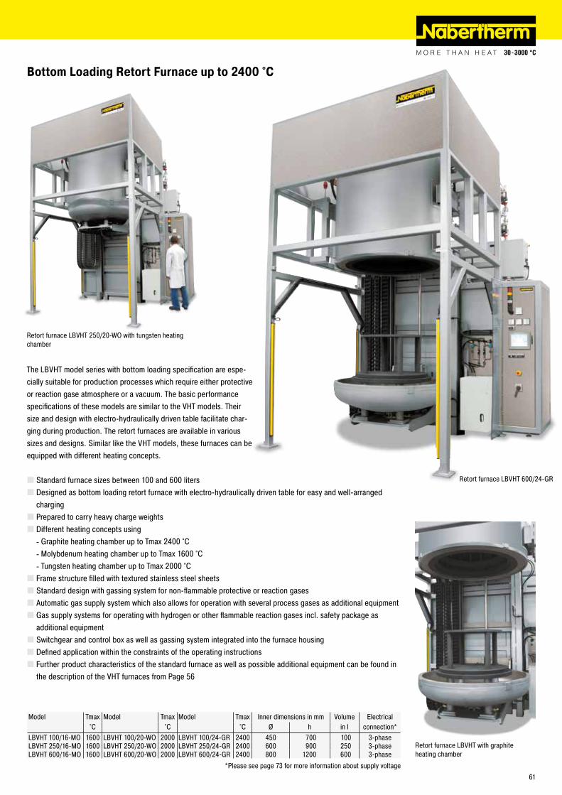
The LBVHT model series with bottom loading specification are espe-cially suitable for production processes which require either protective or reaction gase atmosphere or a vacuum. The basic performance specifications of these models are similar to the VHT models. Their size and design with electro-hydraulically driven table facilitate char-ging during production. The retort furnaces are available in various sizes and designs. Similar like the VHT models, these furnaces can be equipped with different heating concepts.
� Standard furnace sizes between 100 and 600 liters � Designed as bottom loading retort furnace with electro-hydraulically driven table for easy and well-arranged charging � Prepared to carry heavy charge weights � Different heating concepts using
- Graphite heating chamber up to Tmax 2400 °C - Molybdenum heating chamber up to Tmax 1600 °C - Tungsten heating chamber up to Tmax 2000 °C
� Frame structure filled with textured stainless steel sheets � Standard design with gassing system for non-flammable protective or reaction gases � Automatic gas supply system which also allows for operation with several process gases as additional equipment � Gas supply systems for operating with hydrogen or other flammable reaction gases incl. safety package as additional equipment � Switchgear and control box as well as gassing system integrated into the furnace housing � Defined application within the constraints of the operating instructions � Further product characteristics of the standard furnace as well as possible additional equipment can be found in the description of the VHT furnaces from Page 56
Bottom Loading Retort Furnace up to 2400 °C
Retort furnace LBVHT 250/20-WO with tungsten heating chamber
Retort furnace LBVHT with graphite heating chamber
Model Tmax Model Tmax Model Tmax Inner dimensions in mm Volume Electrical°C °C °C Ø h in l connection*
LBVHT 100/16-MO 1600 LBVHT 100/20-WO 2000 LBVHT 100/24-GR 2400 450 700 100 3-phaseLBVHT 250/16-MO 1600 LBVHT 250/20-WO 2000 LBVHT 250/24-GR 2400 600 900 250 3-phaseLBVHT 600/16-MO 1600 LBVHT 600/20-WO 2000 LBVHT 600/24-GR 2400 800 1200 600 3-phase
*Please see page 73 for more information about supply voltage
Retort furnace LBVHT 600/24-GR
61
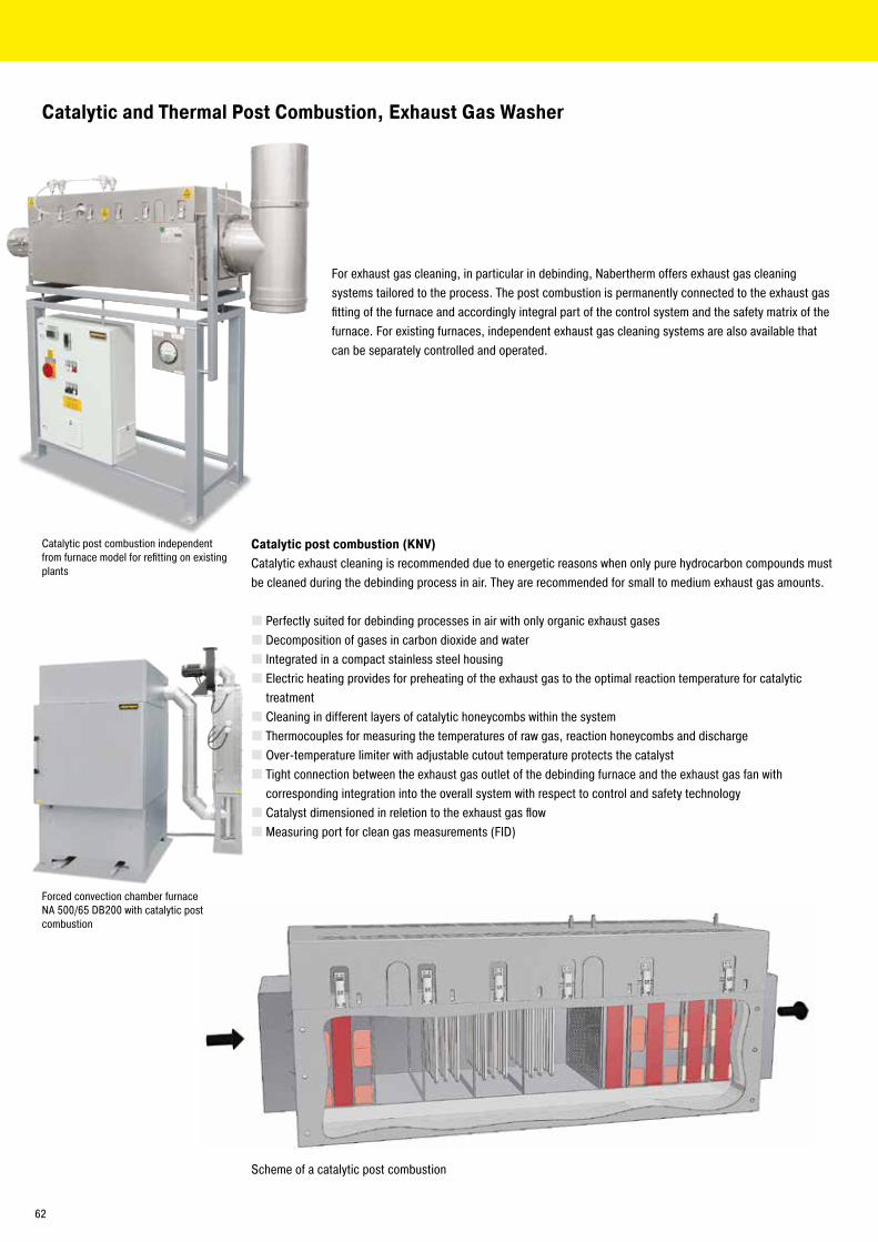
Catalytic and Thermal Post Combustion, Exhaust Gas Washer
For exhaust gas cleaning, in particular in debinding, Nabertherm offers exhaust gas cleaning systems tailored to the process. The post combustion is permanently connected to the exhaust gas fitting of the furnace and accordingly integral part of the control system and the safety matrix of the furnace. For existing furnaces, independent exhaust gas cleaning systems are also available that can be separately controlled and operated.
Forced convection chamber furnace NA 500/65 DB200 with catalytic post combustion
Catalytic post combustion independent from furnace model for refitting on existing plants
Scheme of a catalytic post combustion
Catalytic post combustion (KNV)Catalytic exhaust cleaning is recommended due to energetic reasons when only pure hydrocarbon compounds must be cleaned during the debinding process in air. They are recommended for small to medium exhaust gas amounts.
� Perfectly suited for debinding processes in air with only organic exhaust gases � Decomposition of gases in carbon dioxide and water � Integrated in a compact stainless steel housing � Electric heating provides for preheating of the exhaust gas to the optimal reaction temperature for catalytic treatment � Cleaning in different layers of catalytic honeycombs within the system � Thermocouples for measuring the temperatures of raw gas, reaction honeycombs and discharge � Over-temperature limiter with adjustable cutout temperature protects the catalyst � Tight connection between the exhaust gas outlet of the debinding furnace and the exhaust gas fan with corresponding integration into the overall system with respect to control and safety technology � Catalyst dimensioned in reletion to the exhaust gas flow � Measuring port for clean gas measurements (FID)
62
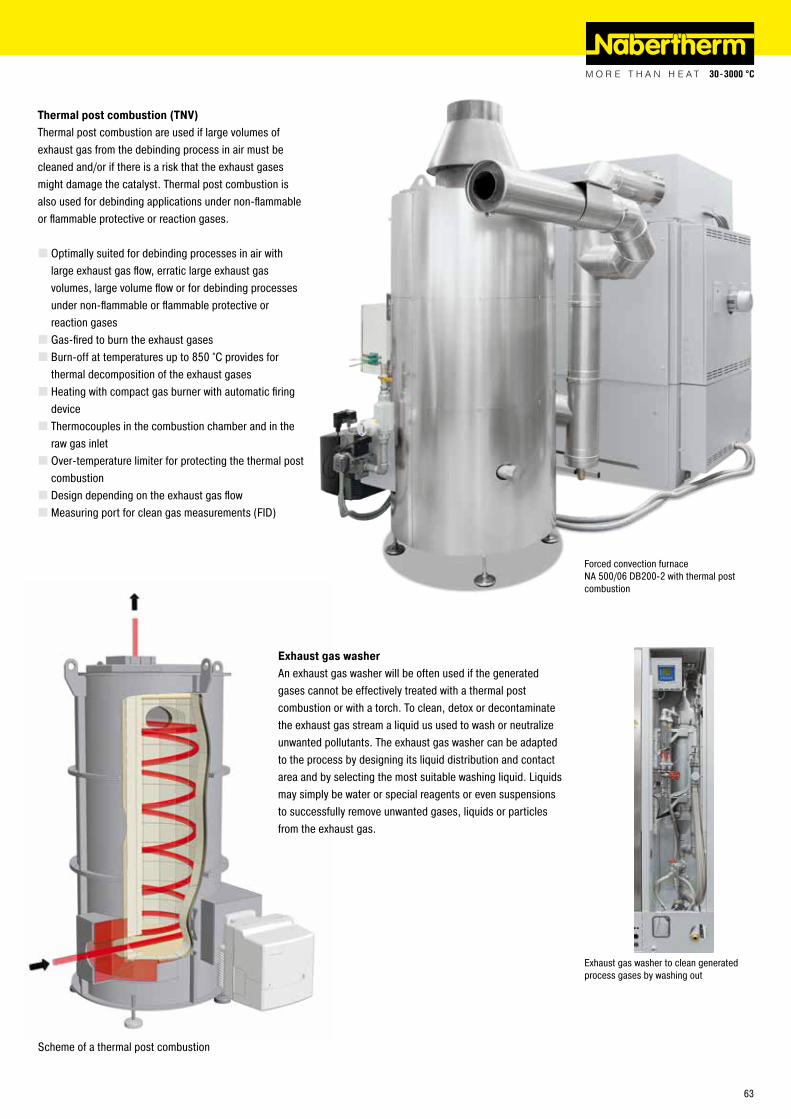
Forced convection furnace NA 500/06 DB200-2 with thermal post combustion
Exhaust gas washer to clean generated process gases by washing out
Thermal post combustion (TNV)Thermal post combustion are used if large volumes of exhaust gas from the debinding process in air must be cleaned and/or if there is a risk that the exhaust gases might damage the catalyst. Thermal post combustion is also used for debinding applications under non-flammable or flammable protective or reaction gases.
� Optimally suited for debinding processes in air with large exhaust gas flow, erratic large exhaust gas volumes, large volume flow or for debinding processes under non-flammable or flammable protective or reaction gases � Gas-fired to burn the exhaust gases � Burn-off at temperatures up to 850 °C provides for thermal decomposition of the exhaust gases � Heating with compact gas burner with automatic firing device � Thermocouples in the combustion chamber and in the raw gas inlet � Over-temperature limiter for protecting the thermal post combustion � Design depending on the exhaust gas flow � Measuring port for clean gas measurements (FID)
Scheme of a thermal post combustion
Exhaust gas washerAn exhaust gas washer will be often used if the generated gases cannot be effectively treated with a thermal post combustion or with a torch. To clean, detox or decontaminate the exhaust gas stream a liquid us used to wash or neutralize unwanted pollutants. The exhaust gas washer can be adapted to the process by designing its liquid distribution and contact area and by selecting the most suitable washing liquid. Liquids may simply be water or special reagents or even suspensions to successfully remove unwanted gases, liquids or particles from the exhaust gas.
63
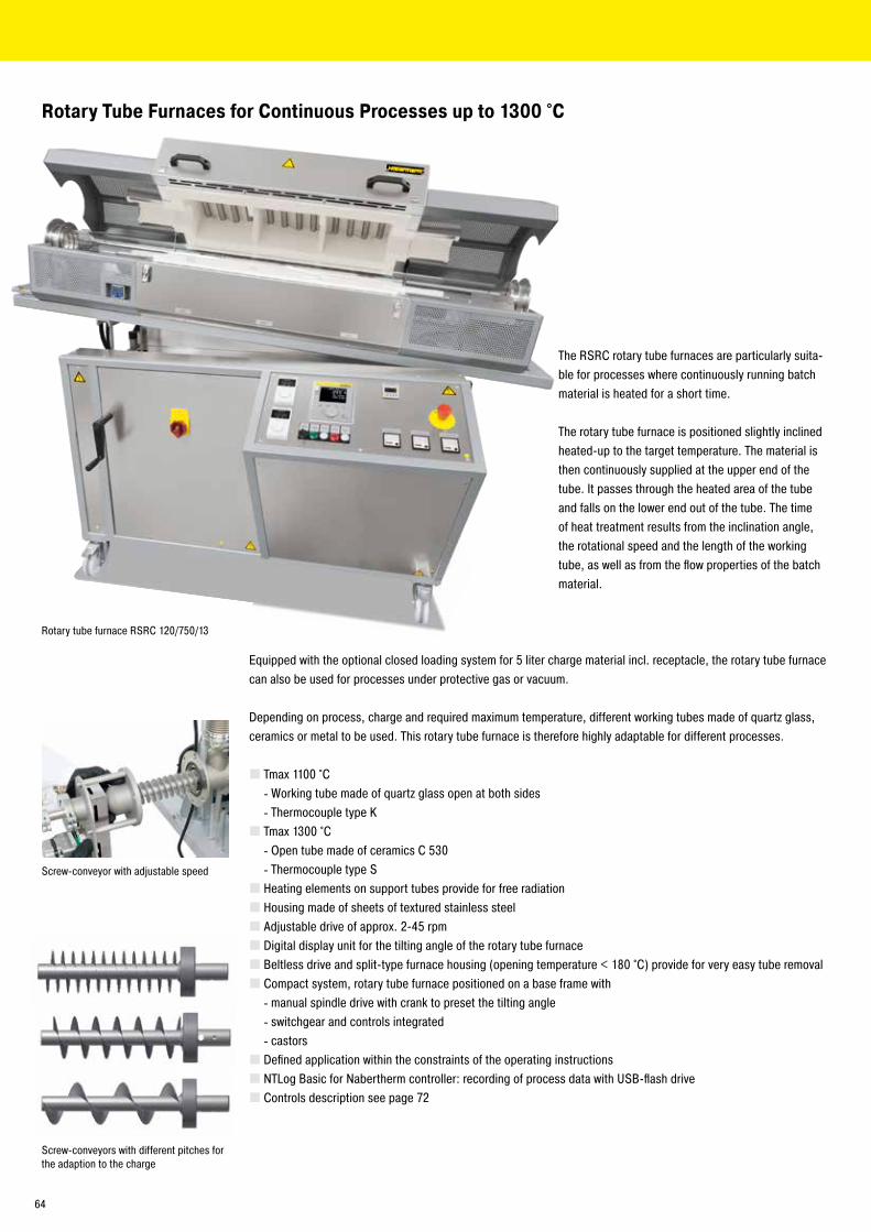
The RSRC rotary tube furnaces are particularly suita-ble for processes where continuously running batch material is heated for a short time.
The rotary tube furnace is positioned slightly inclined heated-up to the target temperature. The material is then continuously supplied at the upper end of the tube. It passes through the heated area of the tube and falls on the lower end out of the tube. The time of heat treatment results from the inclination angle, the rotational speed and the length of the working tube, as well as from the flow properties of the batch material.
Equipped with the optional closed loading system for 5 liter charge material incl. receptacle, the rotary tube furnace can also be used for processes under protective gas or vacuum.
Depending on process, charge and required maximum temperature, different working tubes made of quartz glass, ceramics or metal to be used. This rotary tube furnace is therefore highly adaptable for different processes.
� Tmax 1100 °C - Working tube made of quartz glass open at both sides - Thermocouple type K
� Tmax 1300 °C - Open tube made of ceramics C 530 - Thermocouple type S
� Heating elements on support tubes provide for free radiation � Housing made of sheets of textured stainless steel � Adjustable drive of approx. 2-45 rpm � Digital display unit for the tilting angle of the rotary tube furnace � Beltless drive and split-type furnace housing (opening temperature < 180 °C) provide for very easy tube removal � Compact system, rotary tube furnace positioned on a base frame with
- manual spindle drive with crank to preset the tilting angle - switchgear and controls integrated - castors
� Defined application within the constraints of the operating instructions � NTLog Basic for Nabertherm controller: recording of process data with USB-flash drive � Controls description see page 72
Rotary Tube Furnaces for Continuous Processes up to 1300 °C
Rotary tube furnace RSRC 120/750/13
Screw-conveyors with different pitches for the adaption to the charge
Screw-conveyor with adjustable speed
64
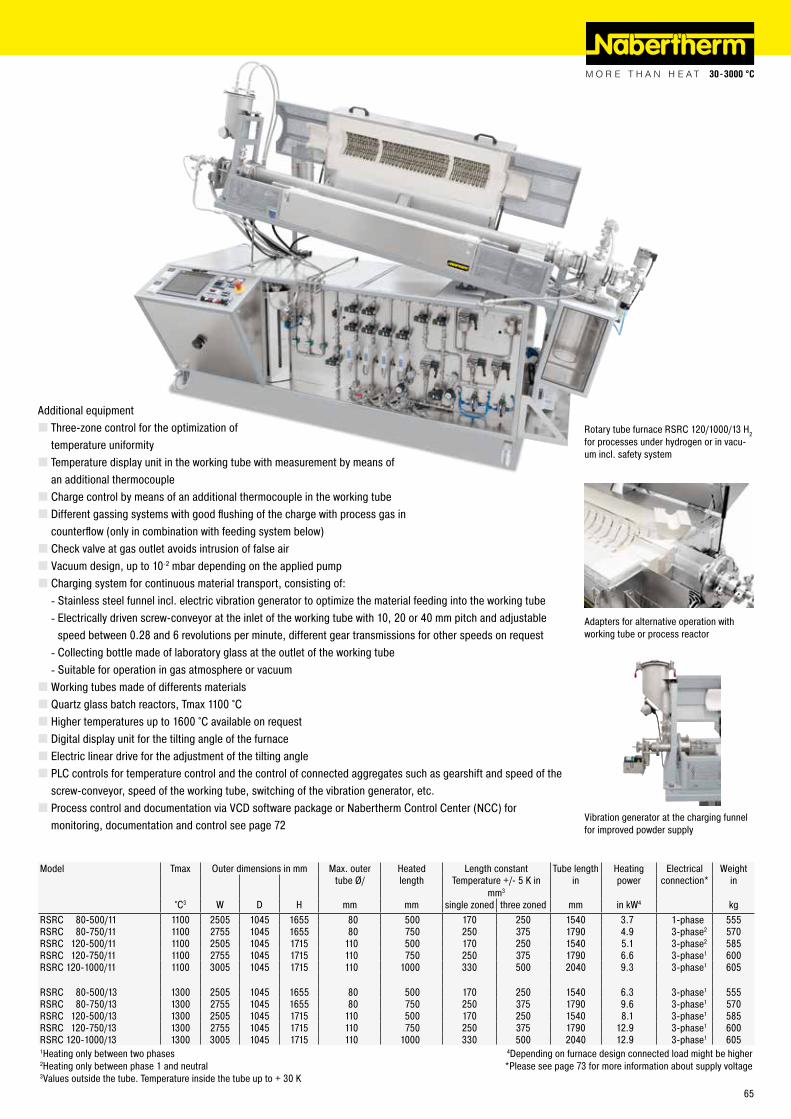
Additional equipment � Three-zone control for the optimization of temperature uniformity � Temperature display unit in the working tube with measurement by means of an additional thermocouple � Charge control by means of an additional thermocouple in the working tube � Different gassing systems with good flushing of the charge with process gas in counterflow (only in combination with feeding system below) � Check valve at gas outlet avoids intrusion of false air � Vacuum design, up to 10-2 mbar depending on the applied pump � Charging system for continuous material transport, consisting of:
- Stainless steel funnel incl. electric vibration generator to optimize the material feeding into the working tube - Electrically driven screw-conveyor at the inlet of the working tube with 10, 20 or 40 mm pitch and adjustable speed between 0.28 and 6 revolutions per minute, different gear transmissions for other speeds on request - Collecting bottle made of laboratory glass at the outlet of the working tube - Suitable for operation in gas atmosphere or vacuum
�Working tubes made of differents materials � Quartz glass batch reactors, Tmax 1100 °C � Higher temperatures up to 1600 °C available on request � Digital display unit for the tilting angle of the furnace � Electric linear drive for the adjustment of the tilting angle � PLC controls for temperature control and the control of connected aggregates such as gearshift and speed of the screw-conveyor, speed of the working tube, switching of the vibration generator, etc. � Process control and documentation via VCD software package or Nabertherm Control Center (NCC) for monitoring, documentation and control see page 72
Rotary tube furnace RSRC 120/1000/13 H2 for processes under hydrogen or in vacu-um incl. safety system
Vibration generator at the charging funnelfor improved powder supply
Adapters for alternative operation with working tube or process reactor
Model Tmax Outer dimensions in mm Max. outer Heated Length constant Tube length Heating Electrical Weighttube Ø/ length Temperature +/- 5 K in
mm3in power connection* in
°C3 W D H mm mm single zoned three zoned mm in kW4 kgRSRC 80-500/11 1100 2505 1045 1655 80 500 170 250 1540 3.7 1-phase 555RSRC 80-750/11 1100 2755 1045 1655 80 750 250 375 1790 4.9 3-phase2 570RSRC 120-500/11 1100 2505 1045 1715 110 500 170 250 1540 5.1 3-phase2 585RSRC 120-750/11 1100 2755 1045 1715 110 750 250 375 1790 6.6 3-phase1 600RSRC 120-1000/11 1100 3005 1045 1715 110 1000 330 500 2040 9.3 3-phase1 605
RSRC 80-500/13 1300 2505 1045 1655 80 500 170 250 1540 6.3 3-phase1 555RSRC 80-750/13 1300 2755 1045 1655 80 750 250 375 1790 9.6 3-phase1 570RSRC 120-500/13 1300 2505 1045 1715 110 500 170 250 1540 8.1 3-phase1 585RSRC 120-750/13 1300 2755 1045 1715 110 750 250 375 1790 12.9 3-phase1 600RSRC 120-1000/13 1300 3005 1045 1715 110 1000 330 500 2040 12.9 3-phase1 6051Heating only between two phases 4Depending on furnace design connected load might be higher2Heating only between phase 1 and neutral *Please see page 73 for more information about supply voltage3Values outside the tube. Temperature inside the tube up to + 30 K
65
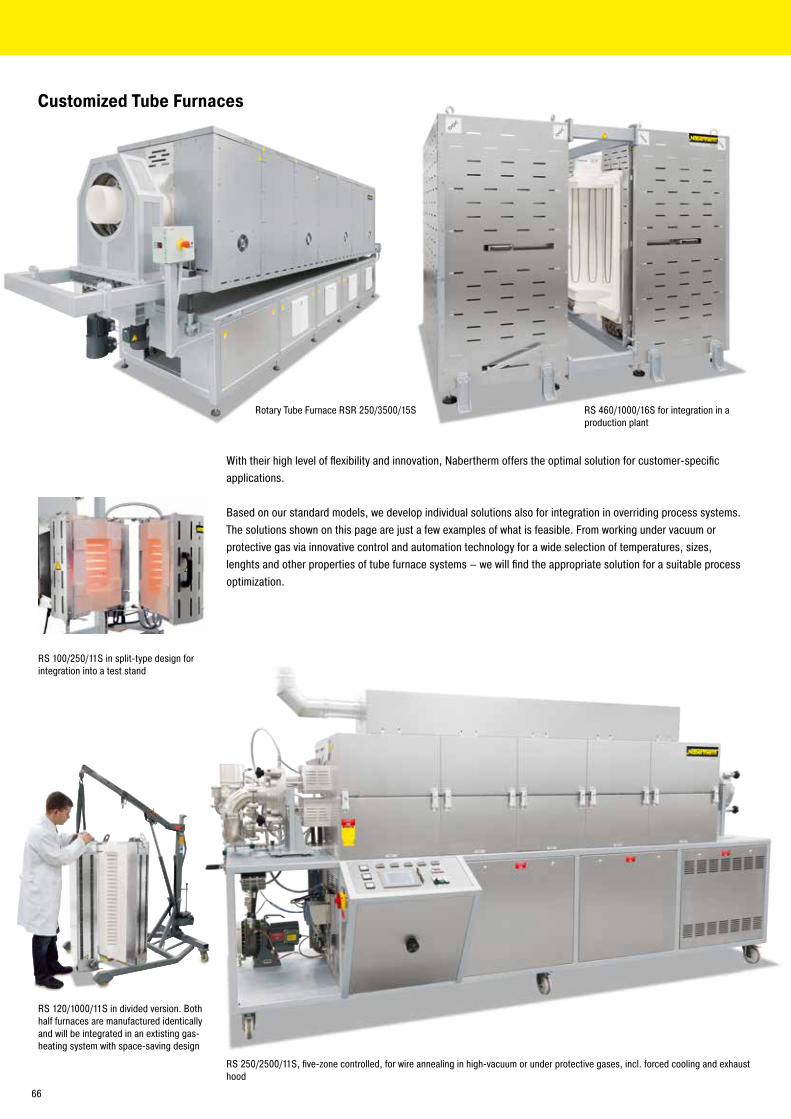
Customized Tube Furnaces
With their high level of flexibility and innovation, Nabertherm offers the optimal solution for customer-specific applications.
Based on our standard models, we develop individual solutions also for integration in overriding process systems. The solutions shown on this page are just a few examples of what is feasible. From working under vacuum or protective gas via innovative control and automation technology for a wide selection of temperatures, sizes, lenghts and other properties of tube furnace systems – we will find the appropriate solution for a suitable process optimization.
RS 100/250/11S in split-type design for integration into a test stand
RS 120/1000/11S in divided version. Both half furnaces are manufactured identically and will be integrated in an extisting gas-heating system with space-saving design
RS 250/2500/11S, five-zone controlled, for wire annealing in high-vacuum or under protective gases, incl. forced cooling and exhaust hood
Rotary Tube Furnace RSR 250/3500/15S RS 460/1000/16S for integration in a production plant
66
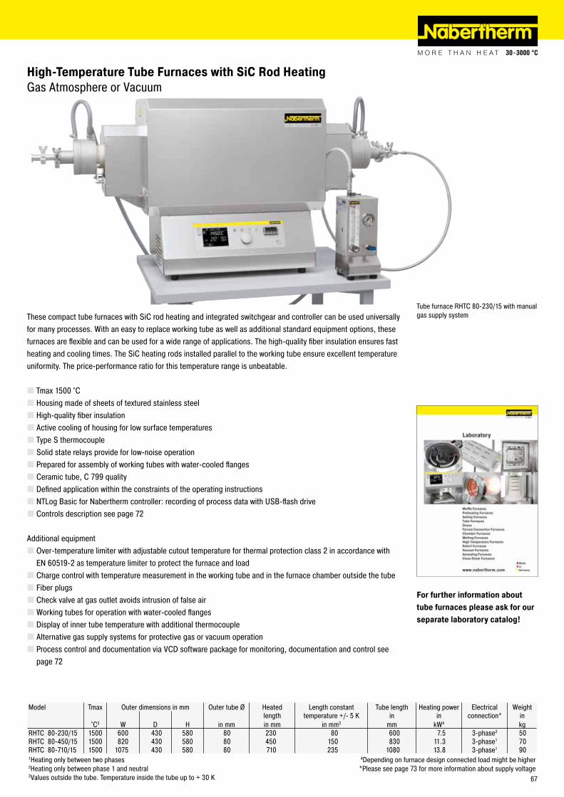
High-Temperature Tube Furnaces with SiC Rod Heating Gas Atmosphere or Vacuum
These compact tube furnaces with SiC rod heating and integrated switchgear and controller can be used universally for many processes. With an easy to replace working tube as well as additional standard equipment options, these furnaces are flexible and can be used for a wide range of applications. The high-quality fiber insulation ensures fast heating and cooling times. The SiC heating rods installed parallel to the working tube ensure excellent temperature uniformity. The price-performance ratio for this temperature range is unbeatable.
� Tmax 1500 °C � Housing made of sheets of textured stainless steel � High-quality fiber insulation � Active cooling of housing for low surface temperatures � Type S thermocouple � Solid state relays provide for low-noise operation � Prepared for assembly of working tubes with water-cooled flanges � Ceramic tube, C 799 quality � Defined application within the constraints of the operating instructions � NTLog Basic for Nabertherm controller: recording of process data with USB-flash drive � Controls description see page 72
Additional equipment � Over-temperature limiter with adjustable cutout temperature for thermal protection class 2 in accordance with EN 60519-2 as temperature limiter to protect the furnace and load � Charge control with temperature measurement in the working tube and in the furnace chamber outside the tube � Fiber plugs � Check valve at gas outlet avoids intrusion of false air �Working tubes for operation with water-cooled flanges � Display of inner tube temperature with additional thermocouple � Alternative gas supply systems for protective gas or vacuum operation � Process control and documentation via VCD software package for monitoring, documentation and control see page 72
Model Tmax Outer dimensions in mm Outer tube Ø Heated Length constant Tube length Heating power Electrical Weight
°C3 W D H in mmlengthin mm
temperature +/- 5 K in mm3
in mm
in kW4
connection* in kg
RHTC 80-230/15 1500 600 430 580 80 230 80 600 7.5 3-phase2 50RHTC 80-450/15 1500 820 430 580 80 450 150 830 11.3 3-phase1 70RHTC 80-710/15 1500 1075 430 580 80 710 235 1080 13.8 3-phase1 901Heating only between two phases 4Depending on furnace design connected load might be higher2Heating only between phase 1 and neutral *Please see page 73 for more information about supply voltage3Values outside the tube. Temperature inside the tube up to + 30 K
Tube furnace RHTC 80-230/15 with manual gas supply system
For further information about tube furnaces please ask for our separate laboratory catalog!
67

Model Tmax Inner dimensions in mm Volume Outer dimensions in mm Heating power Electrical Weight°C w d h in l W D H in kW1 connection* in kg
N 40/14 1400 400 150 600 36 1000 600 1800 36 3-phase 2501Depending on furnace design connected load might be higher *Please see page 73 for more information about supply voltage
Float-Glass Test Kiln with Wire Heating
This chamber furnace was designed to test different types of glass plates such as fire protection glass. In addition to the kiln door, there is a second frame which can be swung in front of the work space into which the test plate is placed. This door is fixed with a special mechanism. The furnace chamber is flat and is heated by element coils supported on ceramic support tubes mounted only on the back wall so that the heat radiates directly onto the glass surface. The chamber furnace achieves exceptionally short cycle times due to the very small chamber volume and high power input.
The laboratory melting furnace SC 8 was specially developed for melting glass in the laboratory. A customer crucible is entered into the furnace from the top. Glass is molten in the crucible. Heating is realized from two sides with powerful SiC rods. With this heating method a maximum furnace temperature of 1500 °C can be achieved. The very effective, multi-layer insulation with long-life lightweight refractory bricks inside the chamber guarantees low outside temperatures even if the furnace is in continuously used.
Laboratory Melting Furnace SC 8 with SiC Rod Heating
Two-side heating with SiC rods
Laboratory melting furnace SC 8 with SiC rod heating for use with a customer crucible
Model Tmax Inner dimensions in mm Volume Outer dimensions in mm Heating power Electrical Weight°C w d h in l W D H in kW1 connection* in kg
SC 8 1500 200 150 250 8 840 715 730 30 3-phase 2901Depending on furnace design connected load might be higher *Please see page 73 for more information about supply voltage
68
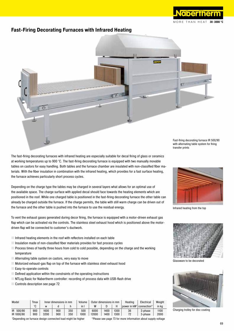
Model Tmax Inner dimensions in mm Volume Outer dimensions in mm Heating Electrical Weight°C w d h in l W D H power in kW1 connection* in kg
IR 500/90 900 1600 900 350 500 6000 1400 1300 36 3-phase 1100IR 1000/90 900 3200 900 350 1000 12000 1400 1300 72 3-phase 20001Depending on furnace design connected load might be higher *Please see page 73 for more information about supply voltage
The fast-firing decorating furnaces with infrared heating are especially suitable for decal firing of glass or ceramics at working temperatures up to 900 °C. The fast-firing decorating furnace is equipped with two manually movable tables on castors for easy handling. Both tables and the furnace chamber are insulated with non-classified fiber ma-terials. With the fiber insulation in combination with the infrared heating, which provides for a fast surface heating, the furnace achieves particularly short process cycles.
Depending on the charge type the tables may be charged in several layers what allows for an optimal use of the available space. The charge surface with applied decal should face towards the heating elements which are positioned in the roof. While one charged table is positioned in the fast-firing decorating furnace the other table can already be charged outside the furnace. If the charge permits, the table with still warm charge can be driven out of the furnace and the other table is pushed into the furnace to use the residual energy.
To vent the exhaust gases generated during decor firing, the furnace is equipped with a motor-driven exhaust gas flap which can be activated via the controls. The stainless steel exhaust hood which is positioned above the motor-driven flap will be connected to customer’s ductwork.
� Infrared heating elements in the roof with reflectors installed on each table � Insulation made of non-classified fiber materials provides for fast process cycles � Process times of hardly three hours from cold to cold possible, depending on the charge and the working temperature � Alternating table system on castors, very easy to move � Motorized exhaust-gas flap on top of the furnace with stainless steel exhaust hood � Easy-to-operate controls � Defined application within the constraints of the operating instructions � NTLog Basic for Nabertherm controller: recording of process data with USB-flash drive � Controls description see page 72
Fast-Firing Decorating Furnaces with Infrared Heating
Fast-firing decorating furnace IR 500/90 with alternating table system for firing transfer prints
Infrared heating from the top
Charging trolley for disc coating
Glassware to be decorated
69
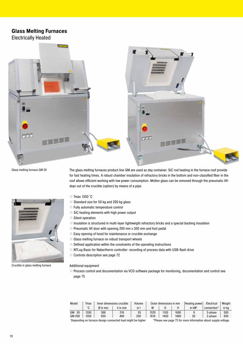
Model Tmax Inner dimensions crucible Volume Outer dimensions in mm Heating power Electrical Weight°C Ø in mm h in mm in l W D H in kW1 connection* in kg
GM 50 1350 368 216 55 1320 1150 1680 9 3-phase 500GM 200 1350 650 400 200 1610 1450 1880 30 3-phase 6501Depending on furnace design connected load might be higher *Please see page 73 for more information about supply voltage
Glass Melting Furnaces Electrically Heated
The glass melting furnaces product line GM are used as day container. SiC rod heating in the furnace roof provide for fast heating times. A robust chamber insulation of refractory bricks in the bottom and non-classified fiber in the roof allows efficient working with low power consumption. Molten glass can be removed through the pneumatic lift-dopr out of the crucible (option) by means of a pipe.
� Tmax 1350 °C � Standard size for 50 kg and 200 kg glass � Fully automatic temperature control � SiC heating elements with high power output � Silent operation � Insulation is structured in multi-layer lightweight refractory bricks and a special backing insulation � Pneumatic lift door with opening 200 mm x 300 mm and foot pedal � Easy opening of hood for maintenance or crucible exchange � Glass melting furnace on robust transport wheels � Defined application within the constraints of the operating instructions � NTLog Basic for Nabertherm controller: recording of process data with USB-flash drive � Controls description see page 72
Additional equipment � Process control and documentation via VCD software package for monitoring, documentation and control see page 75
Crucible in glass melting furnace
Glass melting furnace GM 50
70
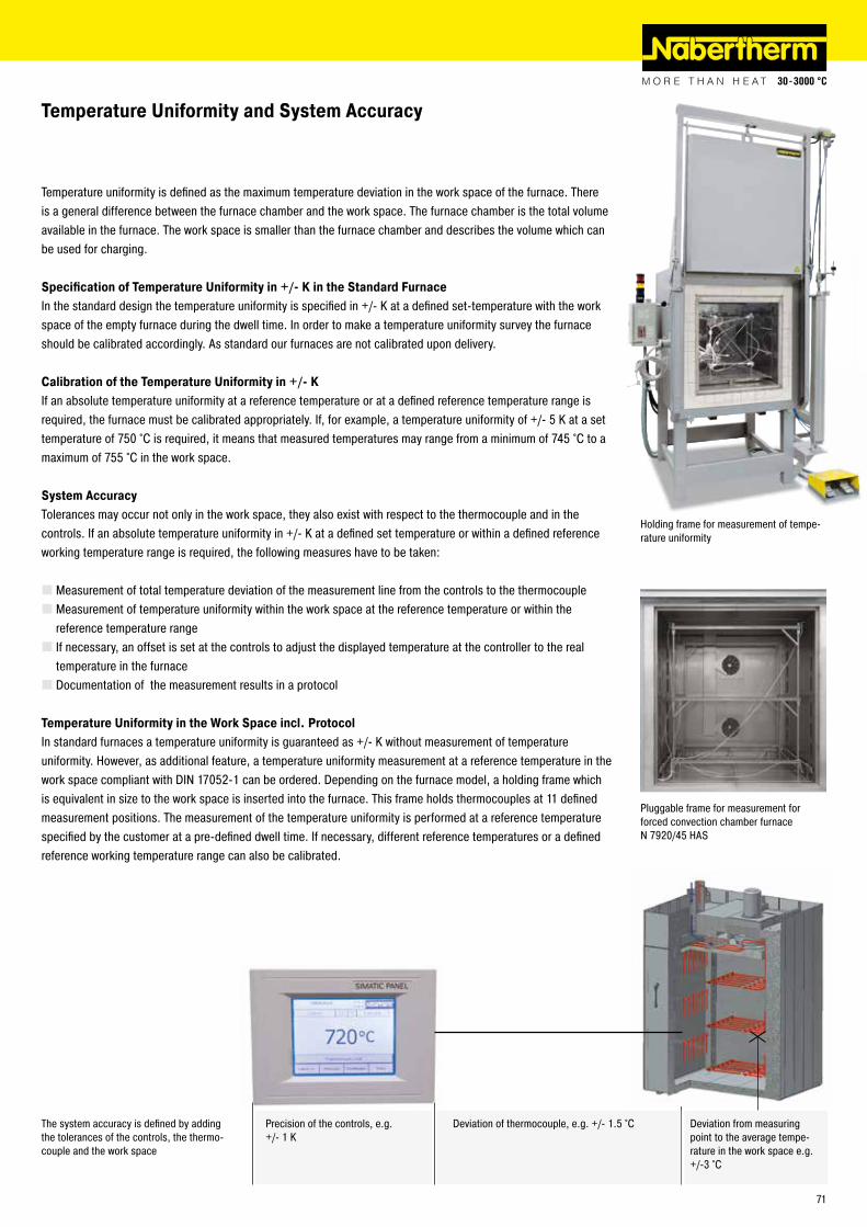
Temperature Uniformity and System Accuracy
Temperature uniformity is defined as the maximum temperature deviation in the work space of the furnace. There is a general difference between the furnace chamber and the work space. The furnace chamber is the total volume available in the furnace. The work space is smaller than the furnace chamber and describes the volume which can be used for charging.
Specification of Temperature Uniformity in +/- K in the Standard FurnaceIn the standard design the temperature uniformity is specified in +/- K at a defined set-temperature with the work space of the empty furnace during the dwell time. In order to make a temperature uniformity survey the furnace should be calibrated accordingly. As standard our furnaces are not calibrated upon delivery.
Calibration of the Temperature Uniformity in +/- KIf an absolute temperature uniformity at a reference temperature or at a defined reference temperature range is required, the furnace must be calibrated appropriately. If, for example, a temperature uniformity of +/- 5 K at a set temperature of 750 °C is required, it means that measured temperatures may range from a minimum of 745 °C to a maximum of 755 °C in the work space.
System AccuracyTolerances may occur not only in the work space, they also exist with respect to the thermocouple and in the controls. If an absolute temperature uniformity in +/- K at a defined set temperature or within a defined reference working temperature range is required, the following measures have to be taken:
� Measurement of total temperature deviation of the measurement line from the controls to the thermocouple � Measurement of temperature uniformity within the work space at the reference temperature or within the reference temperature range � If necessary, an offset is set at the controls to adjust the displayed temperature at the controller to the real temperature in the furnace � Documentation of the measurement results in a protocol
Temperature Uniformity in the Work Space incl. ProtocolIn standard furnaces a temperature uniformity is guaranteed as +/- K without measurement of temperature uniformity. However, as additional feature, a temperature uniformity measurement at a reference temperature in the work space compliant with DIN 17052-1 can be ordered. Depending on the furnace model, a holding frame which is equivalent in size to the work space is inserted into the furnace. This frame holds thermocouples at 11 defined measurement positions. The measurement of the temperature uniformity is performed at a reference temperature specified by the customer at a pre-defined dwell time. If necessary, different reference temperatures or a defined reference working temperature range can also be calibrated.
Holding frame for measurement of tempe-rature uniformity
Deviation from measuring point to the average tempe-rature in the work space e.g. +/-3 °C
Pluggable frame for measurement for forced convection chamber furnace N 7920/45 HAS
The system accuracy is defined by adding the tolerances of the controls, the thermo-couple and the work space
Deviation of thermocouple, e.g. +/- 1.5 °CPrecision of the controls, e.g. +/- 1 K
71
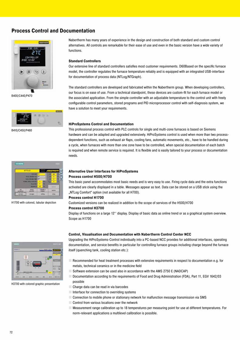
B400/C440/P470
B410/C450/P480
Nabertherm has many years of experience in the design and construction of both standard and custom control alternatives. All controls are remarkable for their ease of use and even in the basic version have a wide variety of functions.
Standard ControllersOur extensive line of standard controllers satisfies most customer requirements. D60Based on the specific furnace model, the controller regulates the furnace temperature reliably and is equipped with an integrated USB-interface for documentation of process data (NTLog/NTGraph).
The standard controllers are developed and fabricated within the Nabertherm group. When developing controllers, our focus is on ease of use. From a technical standpoint, these devices are custom-fit for each furnace model or the associated application. From the simple controller with an adjustable temperature to the control unit with freely configurable control parameters, stored programs and PID microprocessor control with self-diagnosis system, we have a solution to meet your requirements.
HiProSystems Control and DocumentationThis professional process control with PLC controls for single and multi-zone furnaces is based on Siemens hardware and can be adapted and upgraded extensively. HiProSystems control is used when more than two process-dependent functions, such as exhaust air flaps, cooling fans, automatic movements, etc., have to be handled during a cycle, when furnaces with more than one zone have to be controlled, when special documentation of each batch is required and when remote service is required. It is flexible and is easily tailored to your process or documentation needs.
Alternative User Interfaces for HiProSystemsProcess control H500/H700This basic panel accommodates most basic needs and is very easy to use. Firing cycle data and the extra functions activated are clearly displayed in a table. Messages appear as text. Data can be stored on a USB stick using the „NTLog Comfort“ option (not available for all H700).Process control H1700Customized versions can be realized in addition to the scope of services of the H500/H700Process control H3700Display of functions on a large 12‘‘ display. Display of basic data as online trend or as a graphical system overview. Scope as H1700
Control, Visualisation and Documentation with Nabertherm Control Center NCCUpgrading the HiProSystems-Control individually into a PC-based NCC provides for additional interfaces, operating documentation, and service benefits in particular for controlling furnace groups including charge beyond the furnace itself (quenching tank, cooling station etc.):
� Recommended for heat treatment processes with extensive requirements in respect to documentation e.g. for metals, technical ceramics or in the medicine field � Software extension can be used also in accordance with the AMS 2750 E (NADCAP) � Documentation according to the requirements of Food and Drug Administration (FDA), Part 11, EGV 1642/03 possible � Charge data can be read in via barcodes � Interface for connection to overriding systems � Connection to mobile phone or stationary network for malfunction message transmission via SMS � Control from various locations over the network � Measurement range calibration up to 18 temperatures per measuring point for use at different temperatures. For norm-relevant applications a multilevel calibration is possible.
H3700 with colored graphic presentation
H1700 with colored, tabular depiction
Process Control and Documentation
72
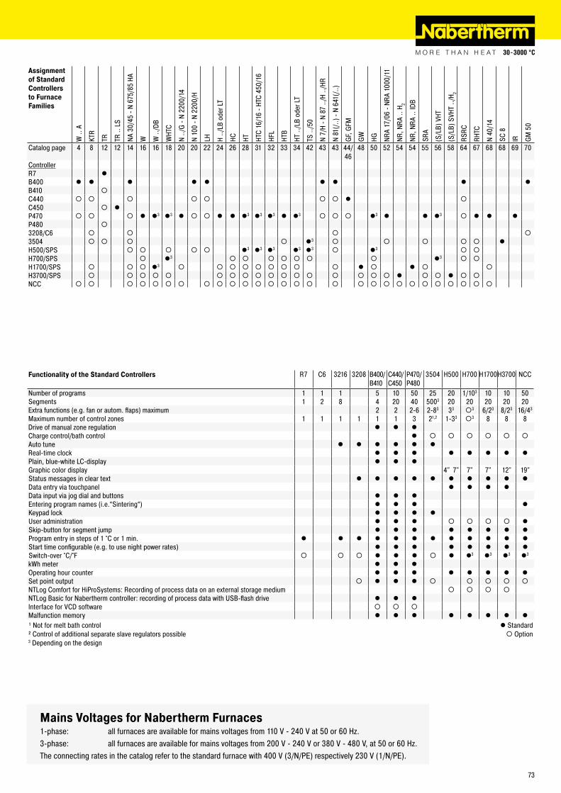
Mains Voltages for Nabertherm Furnaces1-phase: all furnaces are available for mains voltages from 110 V - 240 V at 50 or 60 Hz.3-phase: all furnaces are available for mains voltages from 200 V - 240 V or 380 V - 480 V, at 50 or 60 Hz.The connecting rates in the catalog refer to the standard furnace with 400 V (3/N/PE) respectively 230 V (1/N/PE).
Assignment of Standard Controllers to Furnace Families
W ..
A
KTR
TR TR ..
LS
NA 3
0/45
- N
675/
85 H
A
W W ..
/DB
WHT
C
N ../
G -
N 22
00/1
4
N 10
0 - N
220
0/H
LH H ../
LB o
der L
T
HC HT HTC
16/1
6 - H
TC 4
50/1
6
HFL
HTB
HT ..
/LB
oder
LT
TS ..
/50
N 7/
H - N
87
../H
../HR
N 81
(/..)
- N 6
41(/.
.)
GF,
GFM
GW
HG NRA
17/0
6 - N
RA 1
000/
11
NR, N
RA ..
H2
NR, N
RA ..
IDB
SRA
(S/L
B) V
HT
(S/L
B) S
VHT
../H 2
RSRC
RHTC
N 40
/14
SC 8
IR GM
50
Catalog page 4 8 12 12 14 16 16 18 20 20 22 24 26 28 31 32 33 34 42 43 43 44/46
48 50 52 54 54 55 56 58 64 67 68 68 69 70
ControllerR7 lB400 l l l l l l l l lB410 ¡C440 ¡ ¡ ¡ ¡ ¡ ¡ ¡ l ¡C450 ¡ lP470 ¡ ¡ ¡ l l3 l3 l ¡ ¡ l l l3 l3 l3 l l3 ¡ ¡ ¡ l3 l l l3 ¡ l l lP480 ¡3208/C6 ¡ ¡ ¡ ¡3504 ¡ ¡ ¡ ¡ l3 ¡ ¡ ¡ ¡ ¡ lH500/SPS ¡ ¡ ¡ ¡ ¡ l3 l3 l3 l3 l3 ¡ l3 ¡ ¡H700/SPS ¡ l3 ¡ ¡ ¡ ¡ ¡ ¡ ¡ l3 ¡ ¡H1700/SPS ¡ ¡ ¡ l3 ¡ ¡ ¡ ¡ ¡ ¡ ¡ ¡ ¡ l ¡ l ¡ ¡H3700/SPS ¡ ¡ ¡ ¡ ¡ ¡ ¡ ¡ ¡ ¡ ¡ ¡ ¡ ¡ ¡ ¡ ¡ l ¡ ¡ l ¡ ¡NCC ¡ ¡ ¡ ¡ ¡ ¡ ¡ ¡ ¡ ¡ ¡ ¡ ¡ ¡ ¡ ¡ ¡ ¡ ¡ ¡ ¡ ¡ ¡ ¡ ¡ ¡ ¡ ¡
Functionality of the Standard Controllers R7 C6 3216 3208 B400/B410
C440/C450
P470/P480
3504 H500 H700 H1700H3700 NCC
Number of programs 1 1 1 5 10 50 25 20 1/103 10 10 50Segments 1 2 8 4 20 40 5003 20 20 20 20 20Extra functions (e.g. fan or autom. flaps) maximum 2 2 2-6 2-83 33 ¡3 6/23 8/23 16/43
Maximum number of control zones 1 1 1 1 1 1 3 21,2 1-33 ¡3 8 8 8Drive of manual zone regulation l l lCharge control/bath control l ¡ ¡ ¡ ¡ ¡ ¡Auto tune l l l l l lReal-time clock l l l l l l l lPlain, blue-white LC-display l l lGraphic color display 4" 7" 7" 7" 12" 19"Status messages in clear text l l l l l l l l l lData entry via touchpanel l l l lData input via jog dial and buttons l l lEntering program names (i.e.“Sintering“) l l l lKeypad lock l l l lUser administration l l l ¡ ¡ ¡ ¡ lSkip-button for segment jump l l l l l l l lProgram entry in steps of 1 °C or 1 min. l l l l l l l l l l l lStart time configurable (e.g. to use night power rates) l l l l l l l lSwitch-over °C/°F ¡ ¡ ¡ l l l ¡ l l3 l3 l3 l3
kWh meter l l lOperating hour counter l l l l l l l lSet point output ¡ l l l ¡ ¡ ¡ ¡ ¡NTLog Comfort for HiProSystems: Recording of process data on an external storage medium ¡ ¡ ¡ ¡NTLog Basic for Nabertherm controller: recording of process data with USB-flash drive l l lInterface for VCD software ¡ ¡ ¡Malfunction memory l l l l l l l l¹ Not for melt bath control l Standard² Control of additional separate slave regulators possible ¡ Option3 Depending on the design
73
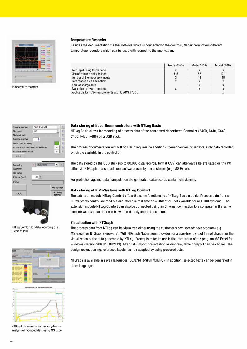
Data storing of Nabertherm controllers with NTLog BasicNTLog Basic allows for recording of process data of the connected Nabertherm Controller (B400, B410, C440, C450, P470, P480) on a USB stick.
The process documentation with NTLog Basic requires no additional thermocouples or sensors. Only data recorded which are available in the controller.
The data stored on the USB stick (up to 80,000 data records, format CSV) can afterwards be evaluated on the PC either via NTGraph or a spreadsheet software used by the customer (e.g. MS Excel).
For protection against data manipulation the generated data records contain checksums.
Data storing of HiProSystems with NTLog ComfortThe extension module NTLog Comfort offers the same functionality of NTLog Basic module. Process data from a HiProSytems control are read out and stored in real time on a USB stick (not available for all H700 systems). The extension module NTLog Comfort can also be connected using an Ethernet connection to a computer in the same local network so that data can be written directly onto this computer.
Visualization with NTGraphThe process data from NTLog can be visualized either using the customer‘s own spreadsheet program (e.g. MS-Excel) or NTGraph (Freeware). With NTGraph Nabertherm provides for a user-friendly tool free of charge for the visualization of the data generated by NTLog. Prerequisite for its use is the installation of the program MS Excel for Windows (version 2003/2010/2013). After data import presentation as diagram, table or report can be chosen. The design (color, scaling, reference labels) can be adapted by using prepared sets.
NTGraph is available in seven languages (DE/EN/FR/SP/IT/CH/RU). In addition, selected texts can be generated in other languages.
NTLog Comfort for data recording of a Siemens PLC
NTGraph, a freeware for the easy-to-read analysis of recorded data using MS Excel
Temperature recorder
Model 6100e Model 6100a Model 6180aData input using touch panel x x xSize of colour display in inch 5.5 5.5 12.1Number of thermocouple inputs 3 18 48Data read-out via USB-stick x x xInput of charge data x xEvaluation software included x x xApplicable for TUS-measurements acc. to AMS 2750 E x
Temperature RecorderBesides the documentation via the software which is connected to the controls, Nabertherm offers different temperature recorders which can be used with respect to the application.
74
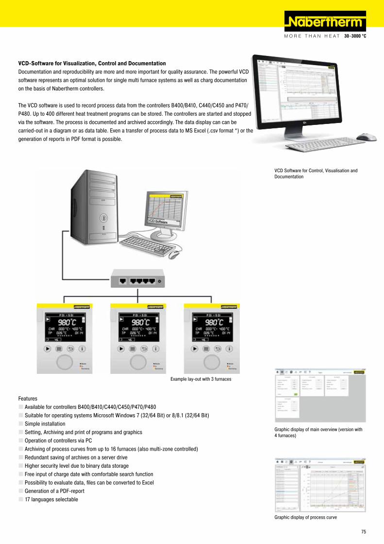
VCD Software for Control, Visualisation and Documentation
Example lay-out with 3 furnaces
Graphic display of main overview (version with 4 furnaces)
Graphic display of process curve
VCD-Software for Visualization, Control and DocumentationDocumentation and reproducibility are more and more important for quality assurance. The powerful VCD software represents an optimal solution for single multi furnace systems as well as charg documentation on the basis of Nabertherm controllers.
The VCD software is used to record process data from the controllers B400/B410, C440/C450 and P470/P480. Up to 400 different heat treatment programs can be stored. The controllers are started and stopped via the software. The process is documented and archived accordingly. The data display can can be carried-out in a diagram or as data table. Even a transfer of process data to MS Excel (.csv format *) or the generation of reports in PDF format is possible.
Features � Available for controllers B400/B410/C440/C450/P470/P480 � Suitable for operating systems Microsoft Windows 7 (32/64 Bit) or 8/8.1 (32/64 Bit) � Simple installation � Setting, Archiving and print of programs and graphics � Operation of controllers via PC � Archiving of process curves from up to 16 furnaces (also multi-zone controlled) � Redundant saving of archives on a server drive � Higher security level due to binary data storage � Free input of charge date with comfortable search function � Possibility to evaluate data, files can be converted to Excel � Generation of a PDF-report � 17 languages selectable
75
www.nabertherm.com
The whole World of Nabertherm: www.nabertherm.com
Reg
No. C
8.1
/08.
16 (e
nglis
ch),
info
rmat
ion
here
in is
sub
ject
to c
hang
e wi
thou
t not
ice.
Nab
erth
erm
ass
umes
no
liabi
lity
for a
ny e
rrors
that
may
app
ear i
n th
is d
ocum
ent.
SwitzerlandNabertherm Schweiz AGAltgraben 31 Nord4624 Härkingen, [email protected]
SpainNabertherm Españac/Marti i Julià, 8 Bajos 7a
08940 Cornellà de Llobregat, [email protected]
USANabertherm Inc.54 Read‘s WayNew Castle, DE 19720, [email protected]
Please visit our website www.nabertherm.com and find out all you want to know about us - and especially about our products.
Besides news and our current calendar of trade fairs, there is also the opportunity to get in touch directly with your local sales office or nearest dealer worldwide.
Professional Solutions for:� Arts & Crafts� Glass� Advanced Materials� Laboratory� Dental� Thermal Process Technology for
Metals, Plastics and Surface Finishing
� Foundry
Headquarters:
Nabertherm GmbHBahnhofstr. 2028865 Lilienthal, [email protected]
Sales Organisation
ChinaNabertherm Ltd. (Shanghai)150 Lane, No. 158 Pingbei Road, Minhang District 201109 Shanghai, [email protected]
FranceNabertherm SARL20, Rue du Cap Vert21800 Quetigny, [email protected]
ItalyNabertherm Italiavia Trento N° 1750139 Florence, [email protected]
Great BritainNabertherm Ltd., United [email protected]
All other Countries: Followhttp://www.nabertherm.com/contacts