catalog 2017 - nupi americas · catalog 2017 oilfield pipes and ... was founded in 2008 by the...
TRANSCRIPT

Catalog 2017
Oilfield Pipes and Fittingsfor the Conveyance of Liquid Hydrocarbons

Important Note - Technical Accuracy
This document contains recommendations and information regarding NUPI Americas products and their installation. It is based on currently available data and is believed to be representative of the product under specific conditions. However, such factors as variations in environment, applications or installation, changes in operating procedure or extrapolation of data may cause different results.
NUPI AMERICAS MAKES NO REPRESENTATION OR WARRANTY, OF ANY KIND, EXPRESS OR IMPLIED, AS TO THE ACCURACY, ADEQUACY, OR COMPLETENESS OF THE RECOMMENDATIONS OR INFORMATION CONTAINED HEREIN.
NUPI Americas neither assumes nor authorizes any representative or other person to assume for it any obligation or liability other than such as is expressly set forth. Attention is drawn to any relevant local and/or national regulations. Information in this document is subject to change without notice. No part of it may be copied, reproduced, translated or reduced to any electronic medium or machine-readable form without prior written consent from NUPI Americas, Inc.
CATALOG: 2017
REVISION: 01
ISSUE DATE: January 2017
FILE NAME: 268US03_Oiltech_Technical_&_Product_Catalogue_letter.pdf


3
Index
Company . . . . . . . . . . . . . . . . . . . . . . . . . . . . . . . . . . . . . . . . . . . . . . . . . . . . . . . . . . . . . .
What is Oiltech. . . . . . . . . . . . . . . . . . . . . . . . . . . . . . . . . . . . . . . . . . . . . . . . . . . . . . . . .
Effects of environmental exposure on physical properties . . . . . . . . . . . . . . . . . .
Installation guidelines. . . . . . . . . . . . . . . . . . . . . . . . . . . . . . . . . . . . . . . . . . . . . . . . . . .
Electrofusion process . . . . . . . . . . . . . . . . . . . . . . . . . . . . . . . . . . . . . . . . . . . . . . . . . .
Electrofusion tools . . . . . . . . . . . . . . . . . . . . . . . . . . . . . . . . . . . . . . . . . . . . . . . . . . . . .
Multifunction welding unit . . . . . . . . . . . . . . . . . . . . . . . . . . . . . . . . . . . . . . . . . . . . . . .
Welding instruction for E/F fittings . . . . . . . . . . . . . . . . . . . . . . . . . . . . . . . . . . . . . . .
Piping pressure test procedure. . . . . . . . . . . . . . . . . . . . . . . . . . . . . . . . . . . . . . . . . . .
Field tests. . . . . . . . . . . . . . . . . . . . . . . . . . . . . . . . . . . . . . . . . . . . . . . . . . . . . . . . . . . . .
Multilayer pipes technical information - OILTECH 300. . . . . . . . . . . . . . . . . . . . . . .
Multilayer pipes technical information - OILTECH 300HT . . . . . . . . . . . . . . . . . . . .
Legend . . . . . . . . . . . . . . . . . . . . . . . . . . . . . . . . . . . . . . . . . . . . . . . . . . . . . . . . . . . . . . .
Product Range OILTECH 300 . . . . . . . . . . . . . . . . . . . . . . . . . . . . . . . . . . . . . . . . . . . .
Pipes. . . . . . . . . . . . . . . . . . . . . . . . . . . . . . . . . . . . . . . . . . . . . . . . . . . . .
Electrofusion fittings. . . . . . . . . . . . . . . . . . . . . . . . . . . . . . . . . . . . . . .
Spigot welding fittings . . . . . . . . . . . . . . . . . . . . . . . . . . . . . . . . . . . . .
Transition fittings . . . . . . . . . . . . . . . . . . . . . . . . . . . . . . . . . . . . . . . . . .
Product Range OILTECH 300 HT . . . . . . . . . . . . . . . . . . . . . . . . . . . . . . . . . . . . . . . . .
Pipe & Fittings. . . . . . . . . . . . . . . . . . . . . . . . . . . . . . . . . . . . . . . . . . . . .
Equipment & Welding Units . . . . . . . . . . . . . . . . . . . . . . . . . . . . . . . . . . . . . . . . . . . . . .
Notes. . . . . . . . . . . . . . . . . . . . . . . . . . . . . . . . . . . . . . . . . . . . . . . . . . . . . . . . . . . . . . . . .
4
5
9
11
16
17
18
20
22
23
24
25
26
27
27
28
31
35
38
38
39
45

4
NUPI AMERICAS, Inc. was founded in 2001 by NUPI Industrie Italiane S.p.A. as its North American
subsidiary for production, sales and marketing activities of its Oiltech, Smartflex, Elofit, Elopress,
Elamid and SmartConduit systems. Today, NUPI AMERICAS is proud to introduce our Niron PP-RCT
piping system in North America. NUPI AMERICAS, Inc. is based in Houston, TX where it established
a warehouse and production facility. Another warehouse dedicated to Niron PP-RCT piping system
is located in Early Branch, SC. In 2015, NUPI Industrie Italiane S.p.A. replaced NUPIGECO S.p.A., that
was founded in 2008 by the merger of NUPI S.p.A. and GECO System S.p.A. – two companies with
more than 40 years of experience in the field.
Since its founding in 2001, NUPI AMERICAS has produced more than 20 million feet of pipe. Production
has steadily increased with in excess of 4 million feet produced in 2013. Nupi Americas produces
Smartflex for the transport of fuels and hazardous fluids (downstream) and Oiltech pipes for the
transport of oil (upstream). The production of lined pipe up to 10” combined with a complete system
of electrofusion and butt fusion fittings allows NUPI AMERICAS to provide cutting edge solutions to
complex technological issues.
NUPI AMERICAS combines high productivity and constant high quality standards while being fully
conscious of the environment. The synergy between research, production, quality control and post-
sales service allowed the company to obtain many international quality certifications for its product
ranges. NUPI AMERICAS’ market leadership is well maintained thanks to high quality products and
the constant attention to our customer’s needs and requirements and by means of an effective team
of people in post-sales service, effective and precise technical assistance and the training of installers.
Company

5
What is Oiltech
Oiltech Piping Systems
Oiltech pipes are extruded as an advanced multilayer structure consisting of a base of HDPE piping that
is internally lined with a chemically resistant liner and bonded together in unitary fashion using a tie
layer. Oiltech pipes can be used in a wider temperature and pressure range than ordinary HDPE and can
guarantee better compatibility to chemicals and lower permeation to hydrocarbons. In addition, Oiltech
pipes are easy and cost effective to install. Supplied in either coils or sticks, they can be handled and
assembled in the same manner as conventional HDPE pipes using the electrofusion welding process.
Oiltech pipes can effectively replace steel in high & low temperature pressure applications, instead
of more expensive unitary layer alternatives that make use of expensive engineering thermoplastics
or piping system made of Reinforced Thermoplastic Piping (RTP).
Oiltech is specifically engineered for conveying hydrocarbons in aggressive environments (e.g. H2S,
CO2) where chemical resistance limits the use of conventional plastics as a unitary piping system for
hydrocarbon applications due to permeability and compatibility concerns.
The use of Oiltech multilayer pipes extruded with an integral lining is an attractive method of protecting
the conventional bulk polymer, e.g. HDPE, from the effects of hydrocarbons and chemical attack.
With metal pipes, corrosion is one of the major problems to cope with. In cases where the transported
fluid is both hot and high in salt, H2S, CO2, and dissolved O2, the lifetime of a carbon steel pipe can be
measured in months, even with an aggressive corrosion inhibition program. Such programs can cost
more than $100,000 per year for even a very limited amount of piping.
Multilayer thermoplastic pipes are the ideal solution for high & low temperature pressure application
and also for lining and rehabilitation of existing pipelines.
Products features & benefits
Light Weight
Pipe Flexibility – Coils or Sticks
Extreme ID Wall Smoothness throughout its service life
Corrosion Resistant
Abrasion Resistant
Excellent against Paraffin and Scale Build-Up
Easy and fast Installation and Repair
GPS Locator system
Multilayer structure
Outer Layer in HDPE > Provides Mechanical Strength and Outer Chemical Protection
Inner Layer in Modified Polyamide > Provides Chemical Resistance and Permeation Barrier
Tie Layer > Binds Together Inner and Outer Layer

6
Adhesion durability
Being PA and HDPE are not compatible, a third adhesive layer (tie layer) must be used to prevent the
delamination of the layers and, consequently, the build up of fluid pockets inside the pipe wall.
PEEL TEST ON OILTECH SAMPLES
Long term adhesion strength
Since hydrocarbons, water and chemicals can decrease the adhesion strength, peel tests at critical
conditions (T and fluids) have been carried out and have demonstrated the maintenance of the property.
Multilayer technology
A proper choice of materials, liner and bulk, may result in outstanding properties for applications as
diverse as petroleum extraction, conveyance of automotive fuels and wastes and hazardous fluids
treatment. Co-extrusion technology can be tuned according to real needs with a remarkable cost/
performance ratio, improving: Corrosion resistance Chemical resistance Impact resistance Abrasion resistance Creep resistance Stress cracking resistance

7
Electrofusion Joining Method
Oiltech is a thermoplastic piping system, and therefore it can be joined using Oiltech electrofusion
fittings that guarantee perfect sealing and joints reliability.
The Electrofusion principle involves a combination of heat, self-generated pressure and time. All of
the Oiltech 300 fittings contain molded-in electrical wires that provide, when energised, the required
heat for welding pipe and fittings together. The resulting joint is stronger than the pipe and fittings, so
the resulting pressure rating of the joint exceeds the pipes and fittings themselves.
Each fitting is identified by a Barcode, which contains the specific welding parameters (required
voltage and welding time), the size and type of fitting, the production facility, batch number and raw
material code.
WELDING PARAMETERS
ELECTROFUSION JOINT MOLDED-IN ELECTRICAL WIRES
2D THERMAL ANALYSYS (THROUGH ANSYS)
WiresFitting
Pipe
XXX000 - 00v - 000s - c.t. 00 min
Traceability codeA 035662
XXX00: FITTING CODE00v: TENSION00s: WELDING TIMEc.t. 00 min: COOLING TIME

8
Oiltech transition fittings
Oiltech 300 Spigot Transition Fittings are available in pipe sizes from 2” to 10”. The fittings are
manufactured in compliance with ASTM F 1973 ‘Standard specification for factory assembled anodeless
risers and transition fittings in PEHD PA11, PA12 fuel and gas distribution systems. Category 1-a
transition joint which provides for pressure tightness and resistance to end loads sufficient to cause
no less than 25% elongation of the PE, PA11 or PA12 piping as described in this standard’.
TENSILE TEST ON OILTECH TRANSITION FITTINGS: leak testing after tensile pull with test method D-638 capable of subjecting the joint to a costant pull rate of 0,2±25% in./min.
TENSILE TEST VIDEO
ASTM F1973_08
Tensile Strength Test at pressure 20 bar / 300 Psi
Assembly condition: with electrofusion coupler
Test condition: 73.4°F
Equipment: Tensile automatic dynamometer
Procedure: Perform leak test at 7 Psi and 450 Psi
for 2 minutes before and after tensile test while still
in tension (elongation 125% original length pipe).
After this test, elongation is increased for more
125% with inside pressure 450 Psi.
Test result: Conform, the pipe broke near the
coupler.
9
Weather resistance
The Oiltech Pipe is protected against degradation caused by ultraviolet rays from direct sunlight. The
polyethylene resin contains 2-2.5% of finely dispersed carbon black. This provides the black color of
Oiltech Pipe and Fittings. Carbon black is the most effective additive for enhancing the weathering
characteristics of polyethylene. Oiltech piping can be safely stored outside in most climates for periods
of many years without danger of loss of physical properties due to ultraviolet (UV) exposure. In general,
Nupi Americas recommends the use of first-in, first-out inventory management procedure.
Installation temperature
Oiltech Piping System can be installed at any ambient temperature condition in which normal installation
operations would continue. In cold weather, however, special procedural recommendations, as outlined
in this catalog, should be followed.
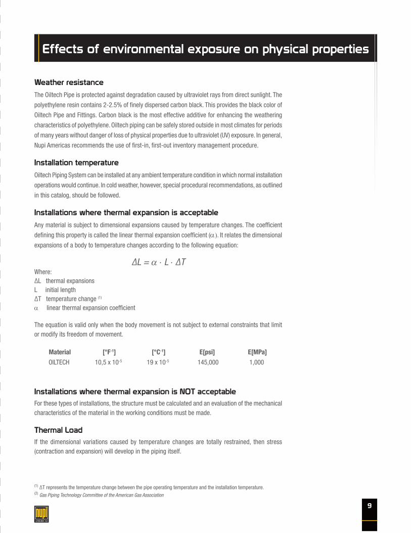
Installations where thermal expansion is acceptable
Any material is subject to dimensional expansions caused by temperature changes. The coefficient
defining this property is called the linear thermal expansion coefficient (α). It relates the dimensional
expansions of a body to temperature changes according to the following equation:
ΔL = α ⋅ L ⋅ ΔTWhere: ΔL thermal expansionsL initial length ΔT temperature change (1)
α linear thermal expansion coefficient
The equation is valid only when the body movement is not subject to external constraints that limit or modify its freedom of movement.
Material [°F-1] [°C-1] E[psi] E[MPa]
OILTECH 10,5 x 10⁻⁵ 19 x 10-5 145,000 1,000
Installations where thermal expansion is NOT acceptableFor these types of installations, the structure must be calculated and an evaluation of the mechanical characteristics of the material in the working conditions must be made.
Thermal LoadIf the dimensional variations caused by temperature changes are totally restrained, then stress (contraction and expansion) will develop in the piping itself.
(1) ΔT represents the temperature change between the pipe operating temperature and the installation temperature.(2) Gas Piping Technology Committee of the American Gas Association
Effects of environmental exposure on physical properties

10
The axial stress is given by:
σ = - E ⋅ΔT
= - E ⋅ α ⋅ ΔT L
Where: ΔL thermal expansionL pipe length E elasticity modulusα linear thermal expansion coefficientΔT temperature change
The minus sign indicates that, for positive T (heating) the tension will be compressive (conventionally assumed as negative), whereas for negative T the tension will be tensile (conventionally assumed as positive).
The axial forces generated inside the pipe are discharged at the pipe ends near the fixed points (ex. valves, pumps, etc.). They generate forces that can be calculated by multiplying the axial stress by the pipe section A:
F = σ ⋅ A = - E ⋅ α ⋅ ΔT ⋅ A
Where: F resulting forceσ thermal stressA cross sectionE elasticity modulus
It is interesting to note that the stress status arising in a situation of inhibited deformation does not depend on the structure’s geometry (e.g. pipe length or cross section) but exclusively on temperature change, expansion coefficient and elasticity modulus.
Pipe damage & repair
Industry surveys indicate the primary cause for repair of plastic piping is from third party damage and
poor workmanship during installation. Risk of damage can be minimized by using careful mapping
and location methods and by proper training and inspection procedures. When repair is required,
an advantage of Oiltech Pipe is its capability of being squeezed to control gas/oil flow quickly and
localize shutdown.
Recommended procedures for repair are outlined in the GPTC (2) Guide as well as the AGA ‘Plastic
Pipe Manual’. Squeeze-off in sections of pipe, which are to be left in the system, should only be done
using approved techniques and properly designed equipment to minimize pipe damage. Procedures
for squeezing-off Oiltech Piping are provided in the squeeze-off section of this catalog.

11
Installation guidelines
Handling
Oiltech Piping System is a tough flexible product that is able to withstand normal installation handling.
However, unusually rough handling of Oiltech Piping System can result in damage to the pipe wall. Care
should be taken to avoid pushing or pulling Oiltech Piping System over or around sharp projections.
Oiltech Piping System is subject to impact damage when dropped from excessive heights or when
heavy objects are dropped upon it, particularly during cold weather. Kinking or buckling should be
avoided and any section of pipe that has been damaged in this manner should be cut out.
Based on pipe pressure tests, a good rule of thumb in determining if a scratched piece of pipe should
be cut out of the piping system is: if the scratch depth is greater than 10% of the pipe wall thickness,
then the section should be removed or repaired.
Unloading & Loading
When unloading or loading a shipment of Oiltech Piping System, forklift operators should be cautioned
against damaging the pipe with the fork or tines of the lift truck. When unloading or loading straight
sticks of pipe, allow for some bending in the middle of the lift. Position forklift tines as far apart as
possible to reduce the amount of bending. This will enable operators to lift the load without raising
the forks to excessive heights which risks dropping the load.
This is particularly important when unloading pipe at temperatures of 40°F or below; under these
conditions, the pipe is stiffer and more susceptible to damage from impact.
When breaking down bulk packs, take care to stand clear of the pipe while strapping
is being cut. Coiled Oiltech contains energy as in a spring. Uncontrolled release, i.e., cutting
of straps, can result in dangerous uncontrolled forces. All safety precautions and proper
equipment is required.
Stringing
Reel trailers can be helpful when stringing out coiled pipe for direct burial, plow-in, pull-in or insertion
renewal. It is helpful when handling coiled pipe to string the pipe out on the ground upon arrival at the
job site. This allows time for the coil set to relax, and will simplify handling and emplacement of the pipe.
When uncoiling pipe by hand, only cut those straps on the coils which are necessary to uncoil outer
rolls; cut internal bands whenever necessary as the coil is unrolled.
Always inspect the pipe as it is being uncoiled and during installation to make sure no damage to the
pipe has occurred during shipment and subsequent handling at the job site.
Dragging
Occasionally, when long strings of pipe are joined together, it is necessary to drag the pipe to where it
will be installed. When the pipe must be dragged over rocky terrain or hard pavement, take precautions
to protect the pipe from abrasion. Sandbags, used tires or short logs may be used to support the pipe
and prevent hard contact with sharp rocks or hard pavement.

12
Cutting
Oiltech Piping System should be cut with pipe cutters designed for plastic pipe. These tools easily
provide the square cut ends that are necessary to provide satisfactory fusion joints. If carpenter or
hacksaws are used to cut the pipe, special care must be taken to ensure square cut ends and to clean
the resultant sawdust from inside the pipe.
Cold weather handling
Oiltech is a tough piping material; yet colder temperatures can reduce resistance to damage from
mechanical abuse, such as impact. Avoid dropping the pipe, especially in cold weather. Although the
recommended method of unloading is to use a forklift or crane, an alternate method is to roll the
sticks of pipe down inclined planks. In all cases the pipe should be inspected for damage.
When handling coiled pipe at temperatures below 40°F, it is helpful to uncoil the pipe that is to be
installed and let it straighten out prior to making the installation. This can be done by gradually
uncoiling the pipe and covering it with dirt at intervals to keep it from coiling up again. Always be
careful when cutting the straps on coils of pipe because the outside end of a coil may spring out when
the strapping is removed.
Oiltech is a complex composite pipe that like common HDPE pipe is susceptible to damage while
installing at temperatures below 50°F, it is preferred the pipe be installed at temperatures above
50°F, but in cases where the pipe cannot be at a 50°F or higher temperature, the pipe should be
carefully installed. Rapid uncoiling or impacting the pipe quickly can cause damage, especially at
conditions below 32°F.
Temperatures near or below freezing will affect polyethylene pipe by increasing stiffness, vulnerability
to impact damage and sensitivity to suddenly applied stress especially when cutting. Polyethylene
pipe will be more difficult to uncoil or field bend in cold weather.
Significant impact or shock loads against a polyethylene pipe that is at freezing or lower temperature
can fracture the pipe. Do not drop pipe. Do not allow pipe to fall off the truck or in to the trench. Do not strike the pipe with handling equipment, tools or other objects. Do not drag pipe sticks at speeds where bouncing against the surface may cause impact damage.
Pipe should be firmly supported on both sides when cutting with a handsaw. This can be done by the
use of the pipe aligner.
Squeeze off technique can be used when the ambient temperature is above 50°F. It is always
recommended to replace the squeezed pipe section (the multilayer pipe structures can be affected
by this procedure due to the different tensile modulus of the involved materials).

13
Low temperature can cause the pipe to fracture at the cut if bending stress is applied. Ice snow and
rain are not harmful to the material but may make storage areas more troublesome for handling
equipment and personnel.
Squeeze-Off
Squeeze-off (or pinch-off) is a means of controlling flow in smaller diameter PE pipe and tubing by
flattening the pipe between parallel bars. Flow control does not imply complete flow stoppage in all
cases. For larger pipes, particularly at higher pressures, some seepage is likely. If the situation will
not allow seepage, then it maybe necessary to vent the pipe between two squeeze-offs. Squeeze-off
practices are not limited to gas applications.
Squeeze-off is applicable to PE pressure pipe up to 16” IPS, and up to 100 psi internal pressure, and
conveying various gases or liquids. Larger sizes and higher pressures may be possible if suitable
commercial equipment is available. Manufacturers of squeeze-off equipment should be consulted
for equipment applicability, availability and capabilities.
Squeeze-off tools should comply with ASTM F 1563(12). Typical squeeze-off tools use a manual
mechanical screw or hydraulic cylinders, incorporate gap stops to prevent over-squeeze, and a
mechanism to prevent accidental bar separation.
Closing and opening rates are key elements to squeezing-off without damaging the pipe. It is necessary
to close slowly and release slowly, with slow release being more important. Squeeze-off procedures
should be in accordance with ASTM F 1041(13) and should be qualified in accordance with ASTM F
1734(14).
Lower temperatures will reduce material flexibility and ductility, so in colder weather, closure and
opening time must be slowed further.
Testing of PE piping has shown that squeeze-off can be performed without compromising the expected
service life of the system, or pipe can be damaged during squeeze-off. Damage occurs:
If the manufacturer’s recommended procedures are not followed, or If the squeeze is held closed too long, or When closure stops are altered or circumvented, or By squeezing-off more than once in the same location.
Pipe known or suspected to have been damaged during squeeze-off should be removed from
the system, or should be reinforced at the squeeze-off point using a full encirclement clamp and
replacement repair scheduled.
Static Electricity Control – When pipe conveying a compressed gas is being flattened, the gas flow
velocity through the flattened area increases. High velocity, dry gas, especially with particles present
in the flow, can generate a static electric charge on pipe surfaces that can discharge to ground. Before
flattening the pipe, the tool should be grounded and procedures to control static charge build-up on
pipe surfaces such as wetting surfaces with conductive fluids and applying conductive films or fabrics
to ground should be employed. Grounding and static control procedures should remain in place for
the entire squeeze-off procedure.

14
Identify the squeezed-off area by wrapping tape around the pipe, or installing a full encirclement
clamp over the area.
Trenching
For direct burial of Oiltech Piping System, trench bottoms should be relatively smooth, continuous and
free of rocks and other debris. When ledge rock, hardpan or boulders are encountered, the bottom
of the trench should be padded with sand or other fine grained fill materials. The trench should be
wide enough to allow (a) fusion in the ditch if required, (b) snaking of the pipe along the bottom of
the trench if needed, and (c) filling and compaction of sidefills. Minimum trench widths can be used
in most instances by joining the pipe before lowering it into the trench.
Generally, sufficient cover must be maintained to provide reasonable protection against anticipated
external stress loads. Oiltech Piping System should be installed at a minimum depth of 24 inches.
Pipe placement in trenches
Oiltech Piping System can be joined either above ground or in the ditch as the situation dictates.
Though most joining can be accomplished above ground, joining that must be done in the ditch should
be well planned to ensure that enough space is available and that proper alignment is achieved.
Care should be taken to avoid buckling, gouging, and other mechanical damage when lowering
Oiltech Piping System into the ditch.
Align all pipe true to line and grade. As mentioned earlier, extremely cold weather makes Oiltech
Piping System stiffer and increases the likelihood of impact damage.
Because plastic pipe contacts as it cools, it is desirable in warm weather to snake the pipe in the
bottom of the trench. This provides for ‘slack’ in the pipeline to be taken up as the pipe cools and
contracts in the ditch prior to backfilling.
Electrostatic
Electrostatic charges are generated through a process caused by the presence (in parts per million
or billion) of ions in the fuel.
Positive or negative ions selectively attach themselves to any interfacial surface in contact with the
fuel, such as the inner wall of the pipe, due to selective chemical absorption.
As a consequence, the inside surface of the pipe acquires a unipolar charge and ions of the opposite
polarity in the fuel are attracted to it. A charged layer then extends from the wall into the fuel of a
thickness that increases with decreasing fuel conductivity. The net charge in the pipe is zero when the
fuel is at rest. When the fuel flows, the ions in the boundary layer tend to be carried along, while the
opposite charge on the wall dissipates to earth at a rate depending primarily upon the pipe material’s
conductivity.
In any piping system, either metal or plastic, the primary source of charge generation is due to the
flow of fuel through the pipe.

15
In addition to the electrostatic charging mechanisms, there is also the possibility of electrostatic charge
being generated by friction with pipe wall and other components.
How does this relate to OILTECH pipe and fittings? Based on the typical fluid flow (≤ 8 miles/hour) there is no risk of hazardous discharges from the
pipe due to the fluid flow. As a rule of good practice, it is recommended to bury all metal components such as valves. It is also recommended to stop up/close off or insulate the welding pins of the electrofusion
fittings, if not buried, after the welding process has been completed.

16
Each fitting is identified by a barcode, which contains the specific welding parameters (required
voltage and welding time), the size and type of fitting, the production facility, batch number and raw
material code.
Oiltech Certified Installers can access the welding unit using their specific Oiltech Card that contains
an ID barcode and the following information:
Classification of the Oiltech Certified Holder
Operator’s name, photograph and number
Company name and location (city, state/province and country)
Training level indicated by the codes listed in the table below
Language
Expiration date
Contact information
This system also allows complete traceability of each fitting.
Oiltech system is based on ELECTROFUSION-WELDING. The fittings have a resistive wire inside which
is connected to the outside cable terminals.
When voltage is applied, this resistance generates the heat needed to melt polyethylene. Energy is
directly transmitted at the interface between the fitting and the pipe causing heat welding of the parts.
When it cools down, the joint is even, strong, safe and reliable.
The main features of Oiltech are the high quality and the reliability of the joints.
Advantages of welding Welded and reliable joint ID after welding is the same as the PIPE ID The connection can be pigged Less expensive than mechanical joint Coupling is stronger than the pipe (the joint is not the weakness)
Electrofusion process

17
Appropriate tools are essential to ensure that the electrofusion welding process is carried out correctly.
The tools required are:
Pipe cutter (model SCUT) – It cuts pipes cleanly at 90° to the
pipe axis without leaving any burrs.
Manual scraper (model RAM) - Used to remove the oxidised
surface layer of the pipe from the welding zone.
Aligner (model ALL) – Used to position and lock the parts to
be welded to eliminate stress and/or tension from the welded
connection during the welding and cooling process.
Isopropyl alcohol (model LID1) – Used to clean the pipe from
any trace of grease.
Revolving scrapers (model RATOR or RAT2) – Used to remove
the oxidised surface layer of the pipe from the welding zone.
Electrofusion tools
Marker (model MARK) - Used to mark the right welding length
on the pipes or spigot ends to insert in the fittings to be welded.

18
All the instructions and guidelines
regarding safety precautions are outlined
in the multifunction welding unit (model
00E9001/110) user’s manual. However,
pay close attention to the following:
The unit can perform testing functions when used with the Pressure Test Unit (model SENS050).
Certified operators are responsible for assurance of recommended power sources. Power sources
must be checked for compliance to the following specifications: -110 VAC, 50 Hz (min.) with a
10% tolerance.
Inspect the multifunction welding unit, power cords and barcode reading device and replace
any damaged components prior to use. Care must be taken not to damage the barcode reading
device.
Download the welding and pressure test reports and erase the data from the memory at the
completion of each job.
GPS - The welding unit records the geographical coordinates of the welded fittings, enabling the
traceability of the fitting years after the installation.
A light version weighing only 29 lbs is also available – item code 00E9001L/110.
New model 00E9001LP/110 - multifunction welding unit incorporated in suitcase with barcode
scanner.
Completely automated - barcode system that reduces human errors.
Ambient temperature measurement that ensures perfect weld regardless of temperature changes.
Welding voltage and resistance measurement 5-42V that protects operators working with the
welding unit.
USB technology - the welding unit has a USB port for easy download of welding reports and
pressure test reports.
110V and 220V versions available.
10,000 welds memory – plenty of memory for a standard installation.
2 operational modes: welding and
pressure testing – once connected with
Pressure Test Unit it allows full pressure
test report.
Multifunction welding unit
19
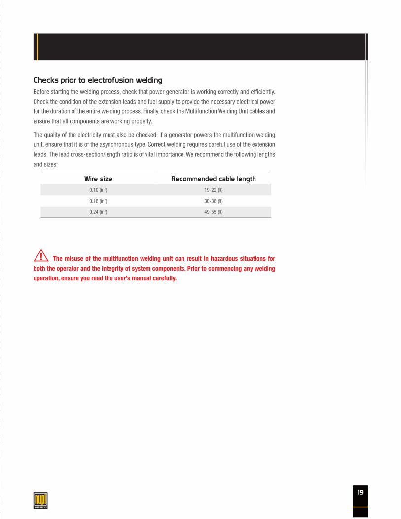
The misuse of the multifunction welding unit can result in hazardous situations for
both the operator and the integrity of system components. Prior to commencing any welding
operation, ensure you read the user’s manual carefully.
Checks prior to electrofusion weldingBefore starting the welding process, check that power generator is working correctly and efficiently.
Check the condition of the extension leads and fuel supply to provide the necessary electrical power
for the duration of the entire welding process. Finally, check the Multifunction Welding Unit cables and
ensure that all components are working properly.
The quality of the electricity must also be checked: if a generator powers the multifunction welding
unit, ensure that it is of the asynchronous type. Correct welding requires careful use of the extension
leads. The lead cross-section/length ratio is of vital importance. We recommend the following lengths
and sizes:
Wire size Recommended cable length
0.10 (in2) 19-22 (ft)
0.16 (in2) 30-36 (ft)
0.24 (in2) 49-55 (ft)

20
Welding instruction for EF fittings
Preparation of the pipe
1 Cut the pipe at right angles with a pipe cutter.
2 Scrape the pipe or spigot surface up to 0.4” beyond the insertion length of the fitting, to remove
the oxidised PE layer. Mechanical scrapers are recommended. Hand scrapers can be used.
3 Remove any mud, dust, grease or other traces of dirt from the pipe or spigot ends and the welding
area of the fitting. Use only isopropanol and a soft wiping cotton cloth without any printing.
4 Wait until the cleaned parts are completely dry, then mark the welding length on the pipes or
spigot ends with a marker pen.
5 Insert the pipe or spigot ends straight into the fitting up to the marked insertion length.
6 Install the aligners in order to keep straight position and avoid stresses during the welding.
AVOID ANY STRESS ON THE WELDING AREA DURING THE WELDING CYCLE AND THE COOLING PHASE

21
Welding instructions
1 Prepare the pipe and fitting to weld following the directions. Make sure that the pipes or spigots
to be welded are lined up and straight without any possibility of movement.
2 Connect the welding cables to the fitting connectors, scan the barcode with the barcode scanner
or enter the welding parameters manually.
3 At the end of the welding cycle, disconnect the cables and wait for the cooling time indicated
on the barcode.
4 The welding data can be downloaded by a USB Memory Device or instantly printed through a
printer.
5 The exact position of the installation can be recorded with the bluetooth GPS.
6 When the cooling time is over, remove the aligners and start the pressure test on the system
using the pressure test unit.
ALWAYS CHECK THE WELDING PARAMETERS BEFORE STARTING THE WELDING CYCLE.

22
Piping pressure test procedure
All Oiltech installations must be pressure tested prior to being placed into service. A pressure gauge
with test pressure at midscale is recommended.
The table below gives testing parameters to be used. Higher test pressures must be approved by the
manufacturer.
If the installation has pressure constraints due to the installation of auxiliary devices, an agreement
can be made to test various profiles. If this is the case, please contact our technical office.
The test method to be followed is the ASTM F2164.
Preferred test liquid: water.
Restraint –The pipeline test section must be restrained against movement in the event of catastrophic
failure. Joints may be exposed for leakage examination provided that restraint is maintained.
The testing equipment capacity and the pipeline test section should be such that the test section can
be pressurised and examined for leaks within test duration time limits. Lower capacity testing and
pressurising equipment may require a shorter test section.
Test equipment and the pipeline test section should be examined before pressure is applied to ensure
that connections are tight and restraints are secured. All low pressure lines and other items not subject
to the test pressure should be disconnected or isolated.
If lower pressure rated components cannot be removed or isolated from the test section, the maximum
test pressure is the pressure rating of the lowest pressure rated component that cannot be isolated
from the test section.
The test section should be completely filled with the test liquid, taking care to bleed off any trapped air.
The test procedure consists of initial expansion and test phases. For the initial expansion phase, the
test section is pressurised to test pressure and test liquid is added as required to maintain maximum
test pressure (1 hour).
For the test phase, the test pressure is reduced by 10 psi. This is the target test pressure. If the
pressure remains steady (within 5% of the target test pressure) for an hour, leakage is not indicated.
If leaks are discovered, depressurise the test section before repairing leaks.
AS IN ANY SYSTEM WHERE PRESSURE IS EMPLOYED, ADEQUATE SAFETY PRECAUTIONS
MUST BE EXERCISED.
SDR 9
Test Duration Test Pressure Test Temperature Test Liquid
2 H 360 PSI * Room Temperature Clean water
* 1,5 x service pressure (not exceeding 360 PSI)

23
Field tests
In 2000, extensive field tests have been carried out in West Texas and New Mexico on 3” OD multilayer
pipes.
The lines have been installed both above and below ground and operated at ambient temperature at
pressures ranging from 30 to 300 psi.
Some of the lines have been sampled over time.
Thermal and rheological analysis has shown that the structural layer has not suffered any significant
damage due to service conditions.

24
Multilayer pipes technical information
Oiltech 300MULTILAYER PIPES
Product description
Oiltech 300 series is a composite piping system developed for flowlines. The polyamide liner provides
chemical and abrasion resistance and excellent compatibility to hydrocarbons.
Features & benefits Reduced permeation to hydrocarbons Smoothness of the ID wall No paraffin build-up Larger bore Excellent chemical and abrasion resistance Ability to resist scale and overall toughness Excellent flow properties throughout its service life Easy to install
Product application
Traditional materials are prone to rapid build up of paraffin in the pipe requiring aggressive maintenance
programs.
Continuous seamless Oiltech pipe runs and the use of large smooth bore electrofusion couplings can
virtually eliminate paraffin build up and the need for hot oiling or chemical treatment. By the use of
NUPI Oiltech pipes and fittings, substantial cuts in maintenance costs can be achieved.
Featuring zero permeation to hydrocarbons, the Oiltech 300 series is the elective choice whenever
environmental issues are at stake.
Oiltech 300 lines can be installed either above ground or in standard ditches 3 feet deep. Thanks
to long spools and the electrofusion technology, the installation time can be drastically reduced to
a minimum with outstanding savings in installation costs. Consult NUPI Americas’ literature before
installing the piping system.
Storage / Handling
Pipes are supplied in bundles or coils. Fittings are packed in bags. Pipes should be stacked on a
reasonably flat surface, free from sharp objects, stones or projections likely to deform or damage
them. Fittings should be stored in their original packaging until use.
Service conditions
Oiltech 300Medium Pressure (SDR 9)
T (°F) PR (psi)
32 300
73 300
105 200
140 125
The above conditions are indicative, please contact NUPI Americas technical office for the proper evaluation of your specific design pameters.

25
Multilayer pipes technical information
Oiltech 300HTMULTILAYER PIPES FOR HIGHER TEMPERATURE APPLICATIONS
Product description
Oiltech 300HT is the new composite piping system specially developed for industrial applications at
high temperatures.
The structural layer is made of PE-RT (Polyethylene of Raised Temperature Resistance) that is a new
family of PE materials with significantly improved long-term strength at high temperatures.
When compared to standard Oiltech 300, the HT (High Temperature) features remarkable properties.
Features & benefits Better pressure strength at high temperature Outstanding stress cracking resistance Reduced permeation to hydrocarbons Smoothness of the ID wall Reduced paraffin build-up Larger bore Excellent chemical and abrasion resistance Ability to resist scale and overall toughness Excellent flow properties throughout its service life Easy to install
Oiltech 300HT is the eligible choice in many applications where the service temperature is between
105°F and 180°F. For lower temperature applications, such as flowlines, NUPI suggests to use Oiltech
300. It can be installed and handled in the same way as standard Oiltech 300, even though it is capable
of higher pressure performance at elevated temperatures. It has the same flexibility as Oiltech 300 and
can be joined by using the same techniques (Electrofusion and Butt Fusion). It is therefore possible to
use the same equipment and accessories for installation.
The Oiltech range is completed by EF fittings molded directly in PE-RT, providing the ideal welding
compatibility with the pipe material.
For Oiltech HT the electrofusion process must always been done on butt welded spigot/pipes, duly
removing the welding bead.
Service conditionsOiltech 300HTMedium Pressure
T (°F) PR (psi)
32 300
73 300
105 210
140 170
158 140
180 120
The above conditions are indicative, please contact NUPI Americas technical office for the proper evaluation of your specific design parameters.
PE-R
T vs
PE1
00
100,0
1000,0
0,1 1 10 100 1000 10000 100000 1000000
MR
S -H
BD
(psi
)
Time (h)
68 °F PE-RT
140 °F PE-RT
180 °F PE-RT
68 °F PE100
140 °F PE100
180 °F PE100
You created this PDF from an application that is not licensed to print to novaPDF printer (http://www.novapdf.com)
PE100 loses long term performances at high
temperature
Hydrostatic Design Basis (HDB)

26
Legend
Nupi Item Code
Nominal Diameter - Pipe external diameter (all dimensions have to be considered in inches with 5% tolerance if not otherwise mentioned)
Standard Dimensional Ration: ratio of pipe outside diameter to wall thickness (OD/S)
Actual outside diameter in inches (all dimensions are allowed to have a tolerance based on the applicable standard)
Wall thickness of the PE layer in inches (all dimensions are allowed to have a tolerance based on the applicable standard)
Type of production (i.e. coil vs. stick)
Unit weight in pounds per feet
Length
Oil
Code
ND
SDR
OD
S
Pack.
Weight
Feet

27
Pipes
High Pressure - 300 PSI - SDR9 - Natural liner Fig. 1A
Code ø Pack. Feet ND OD S min PE ID Weight
(Ibs/ft)
25TOG209C2000 2” COIL 2.000 2 2.48 0.319 1.84 0.661
25TOG309C1000 3” COIL 1.000 3 3.54 0.437 2.67 1.282
25TOG409C500 4” COIL 500 4 4.33 0.516 3.28 1.869
25TOG609S40 6” STICK 40 6 6.30 0.744 4.81 3.843
25TOG609S20 6” STICK 20 6 6.30 0.744 4.81 3.843
25TOG809S40 8” STICK 40 8 7.87 0.976 5.92 6.029
25TOG809S20 8” STICK 20 8 7.87 0.976 5.92 6.029
25TOG1009S40 10” STICK 40 10 9.84 1.204 7.43 9.293
25TOG1009S20 10” STICK 20 10 9.84 1.204 7.43 9.293
OILTECH PIPE
www.nupiamericas.com - [email protected]
ITEM:
C:\Vault_Temp\Disegni\Corinna\Tabelle\Oiltech\Tog\OT10010.dwg
All dimensions have to be considered in inches with 5% tolerance if not otherwise mentioned
DESC:
All right reserved - Drawing cannot be reproduced in anyway, failure todo so will entitle nupigeco to legal action. Information on this document are subject to change without notice
DRAWING No:
SHEET OF REV.TOG POLYETHYLENE PIPES
HIGH PRESSURE - NATURAL LINERSDR 9 300 PSI
OT10010
1 1 -2
ND
/OD
CODE ND OD S min ID Weight (lbs/ft)25TOG209 2 2.48 0.319 1.84 0.66125TOG309 3 3.54 0.437 2.67 1.28225TOG409 4 4.33 0.516 3.28 1.86925TOG609 6 6.30 0.744 4.81 3.84325TOG809 8 7.87 0.976 5.92 6.02925TOG1009 10 9.84 1.204 7.43 9.293
S m
in
ID

28
Fig. 2A
Code ø Pack. ND ID D L1 L H
21OME2 2” 30 2 2.48 3.27 1.85 3.82 3.94
21OME3 3” 32 3 3.54 4.45 2.83 5.75 5.12
21OME4 4” 22 4 4.33 5.35 3.01 6.10 5.67
21OME6 6” 24 6 6.30 7.52 3.43 6.89 7.91
21OME8 8” 14 8 7.87 9.29 3.62 7.28 9.57
21OME10 10” 22 10 9.84 11.65 4.17 8.35 11.81
Fig. 3A
Code Type ø Pack. ND 1 ID 1 ND 2 ID 2 D L1 L2 L H
21ORDE32 A 3” - 2” 30 3 3.54 2 2.48 4.53 2.68 2.44 5.91 5.16
21ORDE42 A 4” - 2” 24 4 4.33 2 2.48 5.31 2.85 2.48 6.30 5.93
21ORDE43 A 4” - 3” 24 4 4.33 3 3.54 5.31 2.87 2.70 6.22 5.93
21ORDE63 A 6” - 3” 12 6 6.30 3 3.54 7.56 3.19 2.83 6.97 8.15
21ORDE64 A 6” - 4” 12 6 6.30 4 4.33 7.56 3.19 3.03 7.17 8.15
21ORDE86 B 8” - 6” 1 8 7.87 6 6.30 - 4.45 4.02 8.86 9.61
21ORDE108 B 10” - 8” 1 10 9.84 8 7.87 - 4.69 3.86 9.53 12.01
Electrofusion Fittings
ELECTROFUSION REDUCER
www.nupiamericas.com - [email protected]
ITEM:
C:\Vault_Temp\Disegni\Corinna\Tabelle\Oiltech\Ome\OT10000.dwg
All dimensions have to be considered in inches with 5% tolerance if not otherwise mentioned
DESC:
All right reserved - Drawing cannot be reproduced in anyway, failure todo so will entitle nupigeco to legal action. Information on this document are subject to change without notice
DRAWING No:
SHEET OF REV.OME ELECTROFUSION COUPLER
OT10000
1 1 -1H
L1
D
L
ND
/ID
CODE ND ID D L1 L H21OME2 2 2.48 3.27 1.85 3.82 3.9421OME3 3 3.54 4.45 2.83 5.75 5.1221OME4 4 4.33 5.35 3.01 6.10 5.6721OME6 6 6.30 7.52 3.43 6.89 7.9121OME8 8 7.87 9.29 3.62 7.28 9.5721OME10 10 9.84 11.65 4.17 8.35 11.81
Type BType A
www.nupiamericas.com - [email protected]
ITEM:
C:\Vault_Temp\Disegni\Corinna\Tabelle\Oiltech\Orde\OT10003.dwg
All dimensions have to be considered in inches with 5% tolerance if not otherwise mentioned
DESC:
All right reserved - Drawing cannot be reproduced in anyway, failure todo so will entitle nupigeco to legal action. Information on this document are subject to change without notice
DRAWING No:
SHEET OF REV.ORDE ELECTROFUSION REDUCER
OT10003
1 2 -1
CODE ND1 ID1 ND2 ID2 D L1 L2 L H21ORDE32 3 3.54 2 2.48 4.53 2.68 2.44 5.91 5.1621ORDE42 4 4.33 2 2.48 5.31 2.85 2.48 6.30 5.9321ORDE43 4 4.33 3 3.54 5.31 2.87 2.70 6.22 5.9321ORDE63 6 6.30 3 3.54 7.56 3.19 2.83 6.97 8.1521ORDE64 6 6.30 4 4.33 7.56 3.19 3.03 7.17 8.15
ND
1/ID
1
ND
2/ID
2
D
H
L1 L2L
www.nupiamericas.com - [email protected]
ITEM:
C:\Vault_Temp\Disegni\Corinna\Tabelle\Oiltech\Orde\OT10003.dwg
All dimensions have to be considered in inches with 5% tolerance if not otherwise mentioned
DESC:
All right reserved - Drawing cannot be reproduced in anyway, failure todo so will entitle nupigeco to legal action. Information on this document are subject to change without notice
DRAWING No:
SHEET OF REV.ORDE ELECTROFUSION REDUCER
OT10003
2 2 -1
L
L2L1
H
ND
2/ID
2
ND
1/ID
1
CODE ND1 ID1 ND2 ID2 D L1 L2 L H21ORDE86 8 7.87 6 6.30 - 4.45 4.02 8.86 9.6121ORDE108 10 9.84 8 7.87 - 4.69 3.86 9.53 12.01
ELECTROFUSION COUPLER

29
Electrofusion Fittings
Fig. 4A
Code ø Pack. ND ID D L1 L2 L H
21OGEM2 2” 20 2 2.48 3.07 2.09 3.46 3.94 5.08
21OGEM3 3” 14 3 3.54 4.53 3.07 4.69 5.24 6.93
21OGEM4 4” 10 4 4.33 5.47 3.27 5.67 6.46 8.43
21OGEM6 6” 8 6 6.30 7.56 3.54 6.81 8.21 10.59
ELECTROFUSION 45° ELBOW
www.nupiamericas.com - [email protected]
ITEM:
C:\Vault_Temp\Disegni\Corinna\Tabelle\Oiltech\Ogem\OT10001.dwg
All dimensions have to be considered in inches with 5% tolerance if not otherwise mentioned
DESC:
All right reserved - Drawing cannot be reproduced in anyway, failure todo so will entitle nupigeco to legal action. Information on this document are subject to change without notice
DRAWING No:
SHEET OF REV.OGEM ELECTROFUSION 90° ELBOW
OT10001
1 1 -2
ND
/ID
L1L2
D
L
H
CODE ND ID D L1 L2 L H21OGEM2 2 2.48 3.07 2.09 3.46 3.94 5.0821OGEM3 3 3.54 4.53 3.07 4.69 5.24 6.9321OGEM4 4 4.33 5.47 3.27 5.67 6.46 8.4321OGEM6 6 6.30 7.56 3.54 6.81 8.21 10.59
ELECTROFUSION 90° ELBOW
www.nupiamericas.com - [email protected]
ITEM:
C:\Vault_Temp\Disegni\Corinna\Tabelle\Oiltech\Ocem\OT10004.dwg
All dimensions have to be considered in inches with 5% tolerance if not otherwise mentioned
DESC:
All right reserved - Drawing cannot be reproduced in anyway, failure todo so will entitle nupigeco to legal action. Information on this document are subject to change without notice
DRAWING No:
SHEET OF REV.OCEM ELECTROFUSION 45° ELBOW
OT10004
1 1 -2
ND/IDD
L1L2
L
H
CODE ND ID D L1 L2 L H21OCEM2 2 2.48 3.15 2.09 2.68 3.94 5.7921OCEM3 3 3.54 4.69 2.76 3.90 5.28 8.1921OCEM4 4 4.33 5.39 3.27 4.49 6.36 9.4921OCEM6 6 6.30 7.56 3.54 5.28 8.21 11.65
Fig. 5A
Code ø Pack. ND ID D L1 L2 L H
21OCEM2 2” 8 2 2.48 3.15 2.09 2.68 3.94 5.79
21OCEM3 3” 20 3 3.54 4.69 2.76 3.90 5.28 8.19
21OCEM4 4” 12 4 4.33 5.39 3.27 4.49 6.36 9.49
21OCEM6 6” 10 6 6.30 7.56 3.54 5.28 8.21 11.65

30
Fig. 6A
Code Type ø Pack. ND 1 ID 1 ND 2 ID 2 S D L1 L2 L3 L H1 H
21OTE2 A 2” 12 2 2.48 2 2.48 0.23 3.15 2.24 2.68 3.54 3.90 4.53 6.14
21OTE3 B 3” 10 3 3.54 3 3.54 - 4.65 2.66 4.72 - 5.28 4.72 7.17
21OTE4 A 4” 7 4 4.33 4 4.33 0.39 5.47 3.27 3.48 5.67 6.16 6.97 9.72
21OTE6 A 6” 8 6 6.30 6 6.30 0.57 7.48 3.43 4.13 5.94 7.93 8.19 11.93
Electrofusion Fittings
ELECTROFUSION EQUAL TEE
Type B
www.nupiamericas.com - [email protected]
ITEM:
C:\Vault_Temp\Disegni\Corinna\Tabelle\Oiltech\Ote\OT10002.dwg
All dimensions have to be considered in inches with 5% tolerance if not otherwise mentioned
DESC:
All right reserved - Drawing cannot be reproduced in anyway, failure todo so will entitle nupigeco to legal action. Information on this document are subject to change without notice
DRAWING No:
SHEET OF REV.OTE ELECTROFUSION EQUAL TEE
OT10002
1 2 -1
ND
1/ID
1
L2
L3L1
S
ND2/ID2
HH
1
L
CODE ND ID1 ND2 ID2 S D L1 L2 L3 L H1 H21OTE2 2 2.48 2 2.48 0.23 3.15 2.24 2.68 3.54 3.90 4.53 6.1421OTE4 4 4.33 4 4.33 0.39 5.47 3.27 3.48 5.67 6.16 6.97 9.7221OTE6 6 6.30 6 6.30 0.57 7.48 3.43 4.13 5.94 7.93 8.19 11.93
D
www.nupiamericas.com - [email protected]
ITEM:
C:\Vault_Temp\Disegni\Corinna\Tabelle\Oiltech\Ote\OT10002.dwg
All dimensions have to be considered in inches with 5% tolerance if not otherwise mentioned
DESC:
All right reserved - Drawing cannot be reproduced in anyway, failure todo so will entitle nupigeco to legal action. Information on this document are subject to change without notice
DRAWING No:
SHEET OF REV.OTE ELECTROFUSION EQUAL TEE
OT10002
2 2 -1
DN
D/ID
L2L1
H1
H
L
CODE ND ID D L1 L2 L H1 H21OTE3 3 3.54 4.65 2.66 4.72 5.28 4.72 7.17
Type A

31
Spigot Welding Fittings
Fig. 7A
Code ø Pack. ND OD S L1 L H
21OGM2 2” 10 2 2.48 0.34 2.76 4.72 6.06
21OGM3 3” 24 3 3.54 0.48 3.50 5.75 7.76
21OGM4 4” 12 4 4.33 0.59 3.43 6.10 8.37
21OGM6 6” 12 6 6.30 0.86 3.98 8.27 11.56
21OGM8 8” 16 8 7.87 1.08 4.57 9.84 13.94
21OGM10 10” 8 10 9.84 1.35 5.31 12.00 17.13
LONG SPIGOT 45° ELBOW
www.nupiamericas.com - [email protected]
ITEM:
C:\Vault_Temp\Disegni\Corinna\Tabelle\Oiltech\Ogm\OT10012.dwg
All dimensions have to be considered in inches with 5% tolerance if not otherwise mentioned
DESC:
All right reserved - Drawing cannot be reproduced in anyway, failure todo so will entitle nupigeco to legal action. Information on this document are subject to change without notice
DRAWING No:
SHEET OF REV.OGM LONG SPIGOT 90° ELBOW
OT10012
1 1 -3N
D/O
DS
L1
L
H
CODE ND OD S L1 L H21OGM2 2 2.48 0.34 2.76 4.72 6.0621OGM3 3 3.54 0.48 3.50 5.75 7.7621OGM4 4 4.33 0.59 3.43 6.10 8.3721OGM6 6 6.30 0.86 3.98 8.27 11.5621OGM8 8 7.87 1.08 4.57 9.84 13.9421OGM10 10 9.84 1.35 5.31 12.00 17.13
LONG SPIGOT 90° ELBOW
www.nupiamericas.com - [email protected]
ITEM:
C:\Vault_Temp\Disegni\Corinna\Tabelle\Oiltech\Ocm\OT10011.dwg
All dimensions have to be considered in inches with 5% tolerance if not otherwise mentioned
DESC:
All right reserved - Drawing cannot be reproduced in anyway, failure todo so will entitle nupigeco to legal action. Information on this document are subject to change without notice
DRAWING No:
SHEET OF REV.OCM LONG SPIGOT 45° ELBOW
OT10011
1 1 -3
L1
ND/OD
S
H
CODE ND OD S L1 H21OCM2 2 2.48 0.34 2.72 6.8921OCM3 3 3.54 0.48 3.54 9.2521OCM4 4 4.33 0.59 3.43 9.5321OCM6 6 6.30 0.86 4.06 12.2421OCM8 8 7.87 1.08 4.61 15.8321OCM10 10 9.84 1.35 5.31 18.19
Fig. 8A
Code ø Pack. ND OD S L1 H
21OCM2 2” 12 2 2.48 0.34 2.72 6.89
21OCM3 3” 25 3 3.54 0.48 3.54 9.25
21OCM4 4” 12 4 4.33 0.59 3.43 9.53
21OCM6 6” 6 6 6.30 0.86 4.06 12.24
21OCM8 8” 16 8 7.87 1.08 4.61 15.83
21OCM10 10” 12 10 9.84 1.35 5.31 18.19

32
Fig. 9A
Code ø Pack. ND OD S L1 L
21OT2 2” 30 2 2.48 0.34 2.76 4.72
21OT3 3” 15 3 3.54 0.48 3.54 5.85
21OT4 4” 9 4 4.33 0.59 3.43 6.10
21OT6 6” 7 6 6.30 0.86 4.33 8.54
21OT8 8” 10 8 7.87 1.08 4.61 9.84
21OT10 10” 14 10 9.84 1.35 5.31 12.01
Spigot Welding Fittings
LONG SPIGOT TEE
www.nupiamericas.com - [email protected]
ITEM:
C:\Vault_Temp\Disegni\Corinna\Tabelle\Oiltech\Ot\OT10013.dwg
All dimensions have to be considered in inches with 5% tolerance if not otherwise mentioned
DESC:
All right reserved - Drawing cannot be reproduced in anyway, failure todo so will entitle nupigeco to legal action. Information on this document are subject to change without notice
DRAWING No:
SHEET OF REV.OT LONG SPIGOT TEE
OT10013
1 1 -2
ND
/OD
S
L1L
CODE ND OD S L1 L21OT2 2 2.48 0.34 2.76 4.7221OT3 3 3.54 0.48 3.54 5.8521OT4 4 4.33 0.59 3.43 6.1021OT6 6 6.30 0.86 4.33 8.5421OT8 8 7.87 1.08 4.61 9.8421OT10 10 9.84 1.35 5.31 12.01
Fig. 10A
Code ø Pack. ND 1 OD 1 S1 ND 2 OD 2 S2 L1 L2 L
21ORD32 3”-2” 24 3 3.54 0.48 2 2.48 0.34 2.80 2.48 5.98
21ORD42 4”-2” 6 4 4.33 0.59 2 2.48 0.34 3.35 2.52 6.89
21ORD43 4”-3” 6 4 4.33 0.59 3 3.54 0.48 2.99 2.68 6.73
21ORD63 6”-3” 6 6 6.30 0.86 3 3.54 0.48 4.25 3.54 9.06
21ORD64 6”-4” 6 6 6.30 0.86 4 4.33 0.59 4.06 3.46 8.46
21ORD86 8”-6” 16 8 7.87 1.08 6 6.30 0.86 4.65 3.98 9.45
21ORD108 10”-8” 1 10 9.84 1.35 8 7.87 1.08 5.12 4.53 11.02
LONG SPIGOT REDUCER
www.nupiamericas.com - [email protected]
ITEM:
C:\Vault_Temp\Disegni\Corinna\Tabelle\Oiltech\Ord\OT10016.dwg
All dimensions have to be considered in inches with 5% tolerance if not otherwise mentioned
DESC:
All right reserved - Drawing cannot be reproduced in anyway, failure todo so will entitle nupigeco to legal action. Information on this document are subject to change without notice
DRAWING No:
SHEET OF REV.ORD LONG SPIGOT REDUCER
OT10016
1 1 -2
CODE ND1 OD1 S1 ND2 OD2 S2 L1 L2 L21ORD32 3 3.54 0.48 2 2.48 0.34 2.80 2.48 5.9821ORD42 4 4.33 0.59 2 2.48 0.34 3.35 2.52 6.8921ORD43 4 4.33 0.59 3 3.54 0.48 2.99 2.68 6.7321ORD63 6 6.30 0.86 3 3.54 0.48 4.25 3.54 9.0621ORD64 6 6.30 0.86 4 4.33 0.59 4.06 3.46 8.4621ORD86 8 7.87 1.08 6 6.30 0.86 4.65 3.98 9.4521ORD108 10 9.84 1.35 8 7.87 1.08 5.12 4.53 11.02
S1
S2
ND
1/O
D1
ND
2/O
D2
L1 L2
L

33
Fig. 11A
Code ø Pack. ND OD S L1 L3 L H ODF SF1 SF2 D2 D3 holes
21OKF2ANSI150 2” 1 2 2.48 0.34 2.95 0.71 4.69 4.02 6.00 0.75 1.00 4.75 0.75 4
21OKF3ANSI150 3” 1 3 3.54 0.48 3.94 0.71 6.08 5.43 7.50 0.94 1.19 6.00 0.75 4
21OKF4ANSI150 4” 1 4 4.33 0.59 3.72 0.87 5.91 6.22 9.00 0.94 1.31 7.50 0.75 8
21OKF6ANSI150 6” 1 6 6.30 0.86 4.33 1.14 7.09 8.35 11.00 1.00 1.56 9.50 0.87 8
21OKF8ANSI150 8” 1 8 7.87 1.08 4.49 1.42 7.87 10.55 13.50 1.13 1.75 11.75 0.87 8
21OKF10ANSI150 10” 1 10 9.84 1.35 5.20 1.50 8.27 12.60 16.00 1.19 1.94 14.25 1.00 12
www.nupiamericas.com - [email protected]
ITEM:
C:\Vault_Temp\Disegni\Corinna\Tabelle\Oiltech\Okf_ansi150\OT10026.dwg
All dimensions have to be considered in inches with 5% tolerance if not otherwise mentioned
DESC:
All right reserved - Drawing cannot be reproduced in anyway, failure todo so will entitle nupigeco to legal action. Information on this document are subject to change without notice
DRAWING No:
SHEET OF REV.OKF_ANSI150
LOOSE FLANGE - 150 lbOT10026
1 1 -1
CODE ND OD S L1 L3 L H ODF SF1 SF2 D2 D3 holes21OKF2ANSI150 2 2.48 0.34 2.95 0.71 4.69 4.02 6.00 0.75 1.00 4.75 0.75 421OKF3ANSI150 3 3.54 0.48 3.94 0.71 6.08 5.43 7.50 0.94 1.19 6.00 0.75 421OKF4ANSI150 4 4.33 0.59 3.72 0.85 5.91 6.22 9.00 0.94 1.31 7.50 0.75 821OKF6ANSI150 6 6.30 0.86 4.33 1.14 7.09 8.35 11.00 1.00 1.56 9.50 0.87 821OKF8ANSI150 8 7.87 1.08 4.49 1.42 7.87 10.55 13.50 1.13 1.75 11.75 0.87 821OKF10ANSI150 10 9.84 1.35 5.20 1.50 8.27 12.60 16.00 1.19 1.94 14.25 1.00 12
L1
L
S
ND
/OD
ODF
H
L3SF1
ANSI (ASA) 150 lb flange
SF2D2
D3
LOOSE FLANGE KIT ANSI 150
Spigot Welding Fittings
www.nupiamericas.com - [email protected]
ITEM:
C:\Vault_Temp\Disegni\Corinna\Tabelle\Oiltech\Okf_ansi300\OT10006.dwg
All dimensions have to be considered in inches with 5% tolerance if not otherwise mentioned
DESC:
All right reserved - Drawing cannot be reproduced in anyway, failure todo so will entitle nupigeco to legal action. Information on this document are subject to change without notice
DRAWING No:
SHEET OF REV.OKF_ANSI300
LOOSE FLANGE - 300 lbOT10006
1 1 -3
CODE ND OD S L1 L3 L H ODF SF1 SF2 D2 D3 holes21OKF2ANSI300 2 2.48 0.34 2.95 0.71 4.69 4.02 6.50 0.88 1.31 5.00 0.75 821OKF3ANSI300 3 3.54 0.48 3.94 0.71 6.08 5.43 8.25 1.13 1.69 6.63 0.87 821OKF4ANSI300 4 4.33 0.59 3.72 0.87 5.91 6.22 10.00 1.25 1.88 7.87 0.87 821OKF6ANSI300 6 6.30 0.86 4.33 1.14 7.09 8.35 12.50 1.44 2.06 10.63 0.87 1221OKF8ANSI300 8 7.87 1.08 4.49 1.42 7.87 10.55 15.00 1.63 2.44 13.00 1.00 1221OKF10ANSI300 10 9.84 1.35 5.20 1.50 8.27 12.60 17.50 1.87 3.75 15.25 1.13 12
L1
L
S
ND
/OD
D2ODF
H
L3 D3
SF1
ANSI (ASA) 300 lb flange
SF2
LOOSE FLANGE KIT ANSI 300
Fig. 12A
Code ø Pack. ND OD S L1 L3 L H ODF SF1 SF2 D2 D3 holes
21OKF2ANSI300 2” 1 2 2.48 0.34 2.95 0.71 4.69 4.02 6.50 0.88 1.31 5.00 0.75 8
21OKF3ANSI300 3” 1 3 3.54 0.48 3.94 0.71 6.08 5.43 8.25 1.13 1.69 6.63 0.87 8
21OKF4ANSI300 4” 1 4 4.33 0.59 3.72 0.87 5.91 6.22 10.00 1.25 1.88 7.87 0.87 8
21OKF6ANSI300 6” 1 6 6.30 0.86 4.33 1.14 7.09 8.35 12.50 1.44 2.06 10.63 0.87 12
21OKF8ANSI300 8” 1 8 7.87 1.08 4.49 1.42 7.87 10.55 15.00 1.63 2.44 13.00 1.00 12
21OKF10ANSI300 10” 1 10 9.84 1.35 5.20 1.50 8.27 12.60 17.50 1.87 3.75 15.25 1.13 12

34
Fig. 13A
Code ø Pack. ND OD S L1 L
21OCAP2 2” 30 2 2.48 0.34 2.76 3.43
21OCAP3 3” 18 3 3.54 0.48 3.19 4.13
21OCAP4 4” 6 4 4.33 0.59 3.54 4.69
21OCAP6 6” 1 6 6.30 0.86 4.25 5.59
21OCAP8 8” 1 8 7.87 1.08 5.24 6.77
21OCAP10 10” 1 10 9.84 1.35 4.61 5.91
LONG SPIGOT CAP
www.nupiamericas.com - [email protected]
ITEM:
C:\Vault_Temp\Disegni\Corinna\Tabelle\Oiltech\Ocap\OT10008.dwg
All dimensions have to be considered in inches with 5% tolerance if not otherwise mentioned
DESC:
All right reserved - Drawing cannot be reproduced in anyway, failure todo so will entitle nupigeco to legal action. Information on this document are subject to change without notice
DRAWING No:
SHEET OF REV.OCAP LONG SPIGOT CAP
OT10008
1 1 -3
ND
/OD
LL1
CODE ND OD S L1 L21OCAP2 2 2.48 0.34 2.76 3.4321OCAP3 3 3.54 0.48 3.19 4.1321OCAP4 4 4.33 0.59 3.54 4.6921OCAP6 6 6.30 0.86 4.25 5.5921OCAP8 8 7.87 1.08 5.24 6.7721OCAP10 10 9.84 1.35 4.61 5.91
S
Spigot Welding Fittings
35
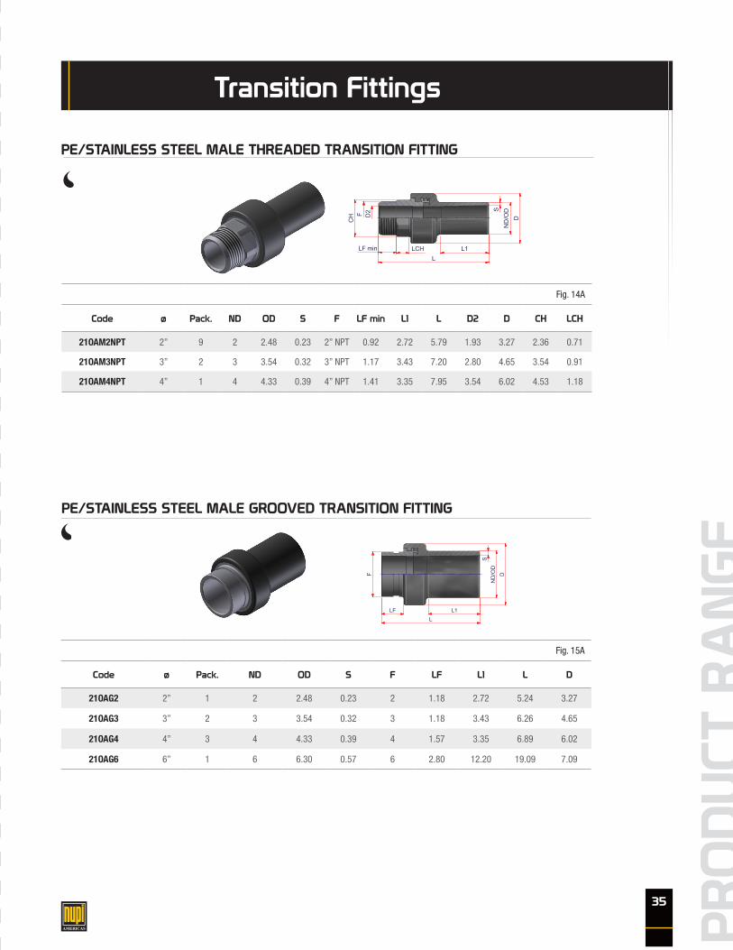
Transition Fittings
Fig. 14A
Code ø Pack. ND OD S F LF min L1 L D2 D CH LCH
21OAM2NPT 2” 9 2 2.48 0.23 2” NPT 0.92 2.72 5.79 1.93 3.27 2.36 0.71
21OAM3NPT 3” 2 3 3.54 0.32 3” NPT 1.17 3.43 7.20 2.80 4.65 3.54 0.91
21OAM4NPT 4” 1 4 4.33 0.39 4” NPT 1.41 3.35 7.95 3.54 6.02 4.53 1.18
www.nupiamericas.com - [email protected]
ITEM:
C:\Vault_Temp\Disegni\Corinna\Tabelle\Oiltech\Oam_npt\OT10005.dwg
All dimensions have to be considered in inches with 5% tolerance if not otherwise mentioned
DESC:
All right reserved - Drawing cannot be reproduced in anyway, failure todo so will entitle nupigeco to legal action. Information on this document are subject to change without notice
DRAWING No:
SHEET OF REV.OAM_NPT PE/STAINLESS STEEL MALE
THREADED TRANSITION FITTING OT10005
1 1 -1
CODE ND OD S F LF min L1 L D2 D CH LCH21OAM2NPT 2 2.48 0.23 2 0.92 2.72 5.79 1.93 3.27 2.36 0.7121OAM3NPT 3 3.54 0.32 3 1.17 3.43 7.20 2.80 4.65 3.54 0.9121OAM4NPT 4 4.33 0.39 4 1.41 3.35 7.95 3.54 6.02 4.53 1.18
D2F
CH
LF min LCHL
L1
SN
D/O
DD
PE/STAINLESS STEEL MALE THREADED TRANSITION FITTING
Fig. 15A
Code ø Pack. ND OD S F LF L1 L D
21OAG2 2” 1 2 2.48 0.23 2 1.18 2.72 5.24 3.27
21OAG3 3” 2 3 3.54 0.32 3 1.18 3.43 6.26 4.65
21OAG4 4” 3 4 4.33 0.39 4 1.57 3.35 6.89 6.02
21OAG6 6” 1 6 6.30 0.57 6 2.80 12.20 19.09 7.09
www.nupiamericas.com - [email protected]
ITEM:
C:\Vault_Temp\Disegni\Corinna\Tabelle\Oiltech\Oag\OT10007.dwg
All dimensions have to be considered in inches with 5% tolerance if not otherwise mentioned
DESC:
All right reserved - Drawing cannot be reproduced in anyway, failure todo so will entitle nupigeco to legal action. Information on this document are subject to change without notice
DRAWING No:
SHEET OF REV.OAG PE/STAINLESS STEEL MALE
GROOVED TRANSITION FITTING OT10007
1 1 -1
SN
D/O
DDF
LF L1L
CODE ND OD S F LF L1 L D21OAG2 2 2.48 0.23 2 1.18 2.72 5.24 3.2721OAG3 3 3.54 0.32 3 1.18 3.43 6.26 4.6521OAG4 4 4.33 0.39 4 1.57 3.35 6.89 6.0221OAG6 6 6.30 0.57 6 2.80 12.20 19.09 7.09
PE/STAINLESS STEEL MALE GROOVED TRANSITION FITTING
36
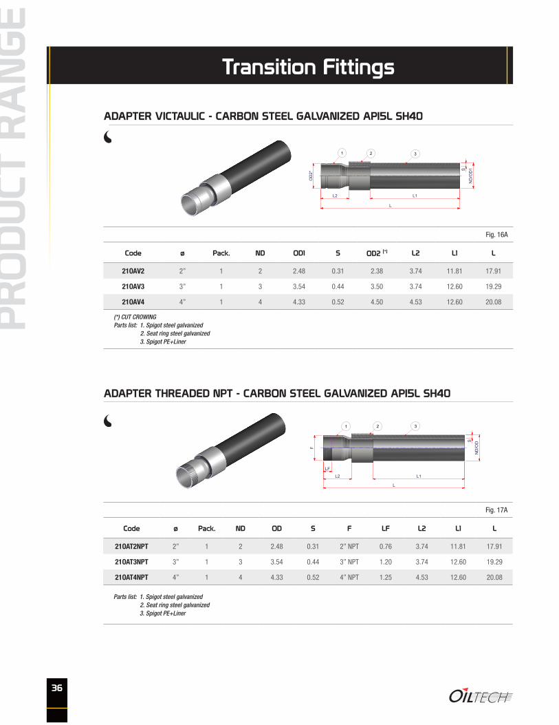
Fig. 16A
Code ø Pack. ND OD1 S OD2 (*) L2 L1 L
21OAV2 2” 1 2 2.48 0.31 2.38 3.74 11.81 17.91
21OAV3 3” 1 3 3.54 0.44 3.50 3.74 12.60 19.29
21OAV4 4” 1 4 4.33 0.52 4.50 4.53 12.60 20.08
(*) CUT CROWINGParts list: 1. Spigot steel galvanized 2. Seat ring steel galvanized 3. Spigot PE+Liner
Transition Fittings
ADAPTER VICTAULIC - CARBON STEEL GALVANIZED API5L SH40
SPIGOT PE + LINER3SEAT RING STEEL GALVANIZED2SPIGOT STEEL GALVANIZED1
PARTS LISTDescriptionPos
www.nupiamericas.com - [email protected]
ITEM:
C:\Vault_Temp\Disegni\Corinna\Tabelle\Oiltech\Oav\OT10014.dwg
All dimensions have to be considered in inches with 5% tolerance if not otherwise mentioned
DESC:
All right reserved - Drawing cannot be reproduced in anyway, failure todo so will entitle nupigeco to legal action. Information on this document are subject to change without notice
DRAWING No:
SHEET OF REV.OAV ADAPTER VITAULIC
OT10014
1 1 -1
CODE ND OD1 S OD2* L2 L1 L21OAV2 2 2.48 0.31 2.38 3.74 11.81 17.9121OAV3 3 3.54 0.44 3.50 3.74 12.60 19.2921OAV4 4 4.33 0.52 4.50 4.53 12.60 20.08
ND
/OD
1S
OD
2*
L2 L1
L
* CUT GROWING
1 2 3
Fig. 17A
Code ø Pack. ND OD S F LF L2 L1 L
21OAT2NPT 2” 1 2 2.48 0.31 2” NPT 0.76 3.74 11.81 17.91
21OAT3NPT 3” 1 3 3.54 0.44 3” NPT 1.20 3.74 12.60 19.29
21OAT4NPT 4” 1 4 4.33 0.52 4” NPT 1.25 4.53 12.60 20.08
Parts list: 1. Spigot steel galvanized 2. Seat ring steel galvanized 3. Spigot PE+Liner
ADAPTER THREADED NPT - CARBON STEEL GALVANIZED API5L SH40
SPIGOT PE + LINER3SEAT RING STEEL GALVANIZED2SPIGOT STEEL GALVANIZED1
PARTS LISTDescriptionPos
www.nupiamericas.com - [email protected]
ITEM:
C:\Vault_Temp\Disegni\Corinna\Tabelle\Oiltech\Oat_npt\OT10015.dwg
All dimensions have to be considered in inches with 5% tolerance if not otherwise mentioned
DESC:
All right reserved - Drawing cannot be reproduced in anyway, failure todo so will entitle nupigeco to legal action. Information on this document are subject to change without notice
DRAWING No:
SHEET OF REV.OAT_NPT
ADAPTER THREADED NPTOT10015
1 1 -1
CODE ND OD S F LF L2 L1 L21OAT2NPT 2 2.48 0.31 2 NPT 0.76 3.74 11.81 17.9121OAT3NPT 3 3.54 0.44 3 NPT 1.20 3.74 12.60 19.2921OAT4NPT 4 4.33 0.52 4 NPT 1.30 4.53 12.60 20.08
LF
L2 L1
L
F
S
ND
/OD
1 2 3

37
Transition Fittings
Fig. 18A
Code ø Pack. ND OD S D SF D1 D2 D3 holes L2 L1 L
21OATF2ANSI150 2” 1 2 2.48 0.31 6.00 0.75 3.62 4.75 0.75 4 5.91 11.81 20.08
21OATF3ANSI150 3” 1 3 3.54 0.44 7.50 0.94 5.00 6.00 0.75 4 6.30 11.02 20.27
21OATF4ANSI150 4” 1 4 4.33 0.52 9.00 0.94 6.18 7.50 0.75 8 7.28 10.04 20.27
Parts list: 1. Spigot steel galvanized 2. Seat ring steel galvanized 3. Spigot PE+Liner
ADAPTER TRANSITION FLANGED ANSI 150
SPIGOT PE + LINER3SEAT RING STEEL GALVANIZED2FLANGE END (ANSI-150 lb) STEEL GALVANIZED1
PARTS LISTDescriptionPos
www.nupiamericas.com - [email protected]
ITEM:
C:\Vault_Temp\Disegni\Corinna\Tabelle\Oiltech\Oatf\OT10019 (2).dwg
All dimensions have to be considered in inches with 5% tolerance if not otherwise mentioned
DESC:
All right reserved - Drawing cannot be reproduced in anyway, failure todo so will entitle nupigeco to legal action. Information on this document are subject to change without notice
DRAWING No:
SHEET OF REV.OATF ADAPTER TRANSITION FLANGED
OT10019 (2)
1 1 0
L1L2
L
SN
D/O
D
DD2
D3
D1
SF1 2 3
CODE ND OD S D SF D1 D2 D3 holes L2 L1 L21OATF2 2 2.48 0.31 6.00 0.75 3.62 4.75 0.75 4 5.91 11.81 20.0821OATF3 3 3.54 0.44 7.50 0.94 5.00 6.00 0.75 4 6.30 11.02 20.2721OATF4 4 4.33 0.52 9.00 0.94 6.18 7.50 0.75 8 7.28 10.04 20.27
Fig. 19A
Code ø Pack. ND OD S D SF D1 D2 D3 holes L2 L1 L
21OATF2ANSI300 2” 1 2 2.48 0.31 6.50 0.87 3.63 5.00 0.75 8 6.30 11.42 20.08
21OATF3ANSI300 3” 1 3 3.54 0.44 8.25 1.13 5.00 6.63 0.87 8 6.69 10.63 20.27
21OATF4ANSI300 4” 1 4 4.33 0.52 10.00 1.25 6.18 7.87 0.87 8 7.68 9.65 20.27
Parts list: 1. Spigot steel galvanized 2. Seat ring steel galvanized 3. Spigot PE+Liner
ADAPTER TRANSITION FLANGED ANSI 300
SPIGOT PE + LINER3SEAT RING STEEL GALVANIZED2FLANGE END (ANSI-150 lb) STEEL GALVANIZED1
PARTS LISTDescriptionPos
www.nupiamericas.com - [email protected]
ITEM:
C:\Vault_Temp\Disegni\Corinna\Tabelle\Oiltech\Oatf\OT10019 (2).dwg
All dimensions have to be considered in inches with 5% tolerance if not otherwise mentioned
DESC:
All right reserved - Drawing cannot be reproduced in anyway, failure todo so will entitle nupigeco to legal action. Information on this document are subject to change without notice
DRAWING No:
SHEET OF REV.OATF ADAPTER TRANSITION FLANGED
OT10019 (2)
1 1 0
L1L2
L
SN
D/O
D
DD2
D3
D1
SF1 2 3
CODE ND OD S D SF D1 D2 D3 holes L2 L1 L21OATF2 2 2.48 0.31 6.00 0.75 3.62 4.75 0.75 4 5.91 11.81 20.0821OATF3 3 3.54 0.44 7.50 0.94 5.00 6.00 0.75 4 6.30 11.02 20.2721OATF4 4 4.33 0.52 9.00 0.94 6.18 7.50 0.75 8 7.28 10.04 20.27

38
Pipe & Fittings
ELECTROFUSION COUPLER 300HTOILTECH PIPE 300HT
ADAPTER VICTAULIC 300HT ADAPTER THREADED NPT 300HT
ADAPTER TRANSITION FLANGEDANSI 150HT
ADAPTER TRANSITION FLANGEDANSI 300HT
on request!

39
Fig. 30
Code Application Pack. Weight (lb)
19SCUT 2”÷8” 1 3.740
19SCUT2 8”÷10” 1 5.940
Equipment & Welding Units
CIRCULAR PIPE CUTTER
Fig. 31
Code Pack. Weight
00LID1 8 bottles 13 FL OZ
HDPE DETERGENT
Fig. 32
Code Type Application Pack. Weight (lb)
00RATOR63200 A 2”÷8” 1 6.6
00RAT2A B 8”÷10” 1 18
SPARE PARTS:
00RATOR63200LR Spare blade for 00RATOR63200
00RATKITRIC Spare blade for 00RAT2A
REVOLVING SCRAPER
A B

40
Equipment & Welding Units
Fig. 33
Code Pack. Weight (lb)
00RAM1 1 0.3
MANUAL SCRAPER
Fig. 34
Code Application Pack. Weight (lb)
00ALL225/4 2”÷ 8” 1 45
00ALL315/4 8”÷10” 1 191
Every tool has four locking points and a swivel joining part to perform all angles
PIPE ALIGNER
41
Fig. 35
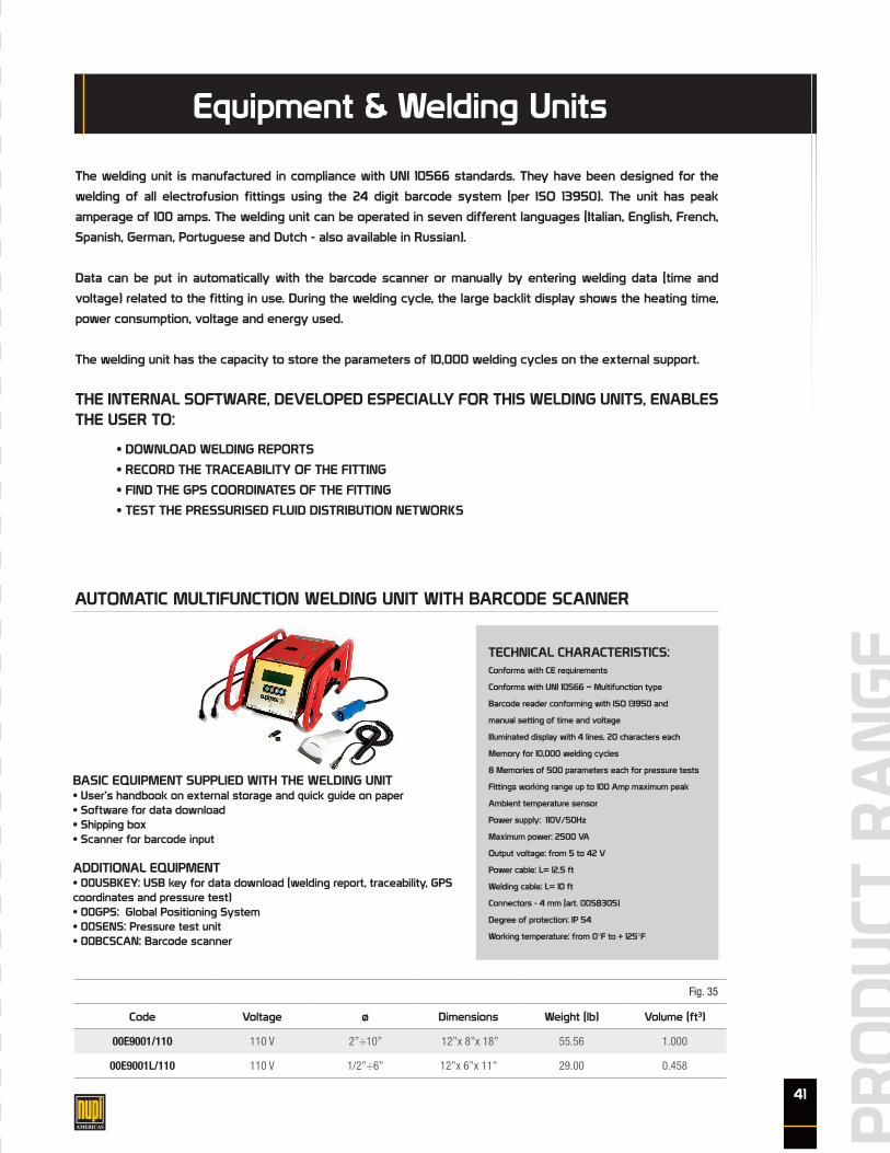
Code Voltage ø Dimensions Weight (lb) Volume (ft3)
00E9001/110 110 V 2”÷10” 12”x 8”x 18” 55.56 1.000
00E9001L/110 110 V 1/2”÷6” 12”x 6”x 11” 29.00 0.458
Equipment & Welding Units
AUTOMATIC MULTIFUNCTION WELDING UNIT WITH BARCODE SCANNER
The welding unit is manufactured in compliance with UNI 10566 standards. They have been designed for the
welding of all electrofusion fittings using the 24 digit barcode system (per ISO 13950). The unit has peak
amperage of 100 amps. The welding unit can be operated in seven different languages (Italian, English, French,
Spanish, German, Portuguese and Dutch - also available in Russian).
Data can be put in automatically with the barcode scanner or manually by entering welding data (time and
voltage) related to the fitting in use. During the welding cycle, the large backlit display shows the heating time,
power consumption, voltage and energy used.
The welding unit has the capacity to store the parameters of 10,000 welding cycles on the external support.
THE INTERNAL SOFTWARE, DEVELOPED ESPECIALLY FOR THIS WELDING UNITS, ENABLES THE USER TO:
• DOWNLOAD WELDING REPORTS
• RECORD THE TRACEABILITY OF THE FITTING
• FIND THE GPS COORDINATES OF THE FITTING
• TEST THE PRESSURISED FLUID DISTRIBUTION NETWORKS
BASIC EQUIPMENT SUPPLIED WITH THE WELDING UNIT• User’s handbook on external storage and quick guide on paper• Software for data download• Shipping box• Scanner for barcode input
ADDITIONAL EQUIPMENT• 00USBKEY: USB key for data download (welding report, traceability, GPS coordinates and pressure test)• 00GPS: Global Positioning System• 00SENS: Pressure test unit• 00BCSCAN: Barcode scanner
TECHNICAL CHARACTERISTICS:Conforms with CE requirements
Conforms with UNI 10566 – Multifunction type
Barcode reader conforming with ISO 13950 and
manual setting of time and voltage
Illuminated display with 4 lines, 20 characters each
Memory for 10,000 welding cycles
8 Memories of 500 parameters each for pressure tests
Fittings working range up to 100 Amp maximum peak
Ambient temperature sensor
Power supply: 110V/50Hz
Maximum power: 2500 VA
Output voltage: from 5 to 42 V
Power cable: L= 12.5 ft
Welding cable: L= 10 ft
Connectors - 4 mm (art. 00S8305)
Degree of protection: IP 54
Working temperature: from 0°F to + 125°F

42
Equipment & Welding Units
Fig. 35A
Code Voltage ø Dimensions Weight (lb) Volume (ft3)
00E9001LP/110 110 V 2”÷10” 20”x 8”x 16” 35.00 1.481
MULTIFUNCTION WELDING UNIT INCORPORATED IN SUITCASEWITH BARCODE SCANNER
The welding unit is manufactured in compliance with UNI 10566 standards. They have been designed for the wel-
ding of all electrofusion fittings using the 24 digit barcode system (per ISO 13950). The unit has peak amperage
of 100 amps. The welding unit can be operated in seven different languages (Italian, English, French, Spanish,
German, Portuguese and Dutch - also available in Russian).
Data can be put in automatically with the barcode scanner or manually by entering welding data (time and volta-
ge) related to the fitting in use. During the welding cycle, the large backlit display shows the heating time, power
consumption, voltage and energy used.
The welding unit has the capacity to store the parameters of 10,000 welding cycles on the external support.
THE INTERNAL SOFTWARE, DEVELOPED ESPECIALLY FOR THIS WELDING UNITS, ENABLES THE USER TO:
• DOWNLOAD WELDING REPORTS
• RECORD THE TRACEABILITY OF THE FITTING
• FIND THE GPS COORDINATES OF THE FITTING
• TEST THE PRESSURISED FLUID DISTRIBUTION NETWORKS
BASIC EQUIPMENT SUPPLIED WITH THE WELDING UNIT• User’s handbook on external storage and quick guide on paper• USB key (2GB) for data download (welding report and pressure test)• Integrated shipping box• Barcode input• Adapters with ø4,7 mm pins
ADDITIONAL EQUIPMENT• 00SENS: Pressure test unit
TECHNICAL CHARACTERISTICS:Conforms with CE requirements
Conforms with UNI 10566 – Multifunction type
Barcode reader conforming with ISO 13950 and
manual setting of time and voltage.
Illuminated display with 4 lines, 20 characters each
Memory for 10,000 welding cycles
8 Memories of 500 parameters each for pressure test
Fittings working range up to 40 Amp maximum peak
Ambient temperature sensor
Power supply: 110V/50Hz
Minimum power: 3Kw
Maximum power: 1500 VA
Output voltage: from 5 to 42 V
Power cable: L= 12.5 ft
Welding cable: L= 10 ft
Dimensions: 20” x 16” x H 8”
Connectors - 4 mm (art. 00S8305)
Degree of protection: IP 54
Working temperature: from 0°F to + 131°F

43
Equipment & Welding Units
Fig. 36
Code ø Pack. Weight (lb)
00S8305 4 mm F 1 0.22
PAIR OF PINS
Fig. 38
Code Pack. Weight (lb) Volume (ft3)
00BCSCAN 1 0.44 0.0001
BARCODE SCANNER
Fig. 39
Code Application Pack.
00USBKEY for 00E9001/110 - 00E9001L/110 1
USB MEMORY DEVICE

44
Fig. 40
Code Pack. Weight (lb)
00GPS 1 0.780
GLOBAL POSITIONING SYSTEM (GPS)
Fig. 41
Code Application Pack. Weight (lb) Volume (ft3)
00SENS050 from 0 to 725 PSI 1 6.17 0.0060
PRESSURE SENSOR
When using the global positioning system (00GPS), the welding unit records the geographical coordinates of the welded fittings, enabling the traceability of the fitting years after its installation.
Thanks to the pressure test unit the welding unit can carry out the inspection of the pressurised distribution network (water and gas connections before and after the meter, fire-prevention networks made of any kind of plastic or metal material).
With the help of the software (00EDP900), the test results are shown on the PC. The welding unit has 8 memories for the pressure test data.
Equipment & Welding Units

45
NOTE: drawings, diagrams, pictures in this catalog are property of Nupi Americas.They shall not be reproduced, even partially, by any means.
Nupi Americas adopts a policy of continuous improvement of the quality of its products and reserves the right to make any change to this catalog without notice. Nupi Americas reserves the right to change the packaging units without
notice. Nupi Americas reserves the right to modify its products without notice.Copyright Nupi Americas Inc. All rights reserved.
Recommendations for waste disposalMetal and plastic material must be disposed of by authorized companies only. Dispose of responsibly.
Notes

Nupi Americas, Inc.
1511 Superior Way
Houston - TX 77039 - U.S.A.
ph. +1 281 590 4471
fax +1 281 590 5268
314 Commerce Parkway
Early Branch - SC 29916 - U.S.A.
ph. +1 803-398-3579
fax: +1 803 398 3639
www.nupiamericas.com