casting technologies - rala · while the whole world is coming closer due to the advancement in...
TRANSCRIPT
A S I A P A C I F I CVol 57 No 2 June 2011
CASTING TECHNOLOGIES
Prin
t Pos
t App
rove
d 25
5003
/0113
5
CHINA • INDIA • TAIWAN • SINGAPORE INDONESIA • THAILAND • PHILIPPINES • MALAYSIA • HONG KONG • JAPAN • EUROPE USA • AUSTRALIA • KOREA • NEW ZEALAND

WARILL ENGINEERING SALES (AUST) PTY LTD
P.O Box 4183, Dandenong South Business Centre, Victoria Australia 3164Phone: 61 3 9794 8400 Fax: 61 3 9794 7232Email: [email protected] Web: www.warill.com.au
AUTO CATALYST BLEND SYSTEM
Over 30 Years of Service to the Foundry Industry
Designed to suit customer’s specifi c requirements
User selectable profi les/features
Multiple Blend Programs
Designed for Ester and Acid Cured resin systems
Spare parts readily available
Can be retro-fi tted to any existing mixer
G SSAALLES (AUST) PTY LTD
ficc
r
HMI Screen features simple to use navigation menu
Variable Speed Drives for Pumps
Stainless Steel Solenoid Operated Diverter Valves
Heavy Duty AC Driven Pumps

METAL Casting Technologies June 2011 1
18
CONTENTS
4442
06 EDITORIAL
10 BRIEFINGS
16 TECHNICAL FEATURES 16 Light alloys, energy sources, and the transport industry By Martin Prekel, Carlos H. Cáceres
24 Towards improving the thermal analysis technique in casting of hypoeutectic aluminum - silicon alloy By Sompob Phetchcrai, John Pearce, Julathep Kajornchaiyakul
30 Semi-Solid Metal (SSM) casting of light metals By PC Maity
36 Development of an environmentally sustainable foundry sand binder By Thang Nguyen, John Carrig, Danny Moran, Xiaoqing Zhang, Sarah Khor
44 BACK TO BASICS Hydrogen in aluminium alloys By Jeff F. Meredith
46 BACK TO FLOOR Safety in induction furnace operations – part 2 By Prof. John H. D. Bautista
48 EVENTS
PRINT + ONLINE EDITIONSEXCLUSIVE EMAIL BROADCASTS
POWERFULINTEGRATED
MEDIAPLATFORM

2 www.metals.rala.com.au
Jimmy Loke Yoon CheeDirector, Yoonsteel Foundry MalaysiaRepresentative of FOMFEIA
Mr Gopal RamaswamiNational Secretary of the Institute of Indian Foundrymen, IndiaEmail: [email protected]
Jack FrostWorld Consulting Specialist Foundry Process [email protected]
Mr Zhang LiboExecutive Vice PresidentChina Foundry [email protected]
Mr Seksan TangkoblabPresident Thai Foundrymen’s Society
Dr John PearceMetals SpecialistMTEC National Metals and MaterialsTechnology Centre, Thailand
Industry AssociationsAustralian Foundry InstituteSouth Australia: The Secretary, PO Box 288, North Adelaide SA 5006Western Australia: The Secretary,[email protected] South Wales: The Secretary, Locked Bag 30, Bankstown NSW 2200, [email protected]: C/- PO Box 89, Acacia Ridge QLD 4110Victoria: PO Box 4284, Dandenong South VIC 3164
Casting Technology New Zealand Inc.PO Box 1925, Wellington, New ZealandTel: +64 4 496 6555, Fax: +64 4 496 6550
China Foundry Association3rd Floor, A-32 Zizhuyuan RdHaidian District, Beijing 100048, CHINATel: +86 10 6841 8899 Fax: +86 10 6845 8356Web: www.foundry-china.com
Federation of Malaysia Foundry & Engineering Industries Association(FOMFEIA), 8 Jalan 1/77B, Off Jalan Changi at Thambi Dollah 55100,Kuala Lumpur, MalaysiaTel: +603 241 8843, Fax: +603 242 1384
Institute of Indian FoundrymenIIF Center, 335 Rajdanga Main Road, East Kolkata Township P.O.Kolkata - 700107 IndiaTel: +91 33 2442 4489, +91 33 2442 6825Fax: +91 33 2442 4491
Japanese Association of Casting TechnologyNoboru Hatano, Technical Director, JACT,Nakamura Bldg, 9-13, 5-chome, Ginza,Chuo-ku, Tokyo, 104 JapanTel: +81 3 3572 6824, Fax: +81 3 3575 4818
Metalworking Industries Association of the Philippines Inc.Pacificador Directo, National President, MIAP, No. 55 Kanlaon St, Mandaluyong,1501 Metro Manila, PhilippinesTel: +632 775 391, Fax: +632 700 413
Philippine Iron & Steel Institute(PISI), Room 518, 5th Floor, Ortigas Building, Ortigas Avenue, Pasig, Metro ManilaTel: +632 631 3065, Fax: +632 631 5781
Philippine Metalcasting Association Inc.(PMAI), 1135 EDSA, Balintawak, Quezon City Metro Manila, PhilippinesTel: +632 352 287, Fax: +632 351 7590
South East Asian Iron & Steel Institute2E 5th Floor Block 2, Worldwide Business ParkJalan Tinju 13/50, 40675 Shah Alam, Selangor MalaysiaTel: +603 5519 1102, Fax: +603 5519 1159, Email: [email protected]
Thai Foundry Association86/8 1st Floor BSID BuildingBureau of Supporting Industries Development Soi Trimitr, Rama IV Road,Klongtoey, Bangkok 10110, ThailandTel: +662 712 2391, Fax: +662 712 2392www.thaifoundry.com
The Materials Process Technology CenterJapan. Kikai Shinko Bldg,3-5-8 Shiba-Koen, Minato-ku, Tokyo, 105 JapanTel: +81 3 3434 3907, Fax: +81 3 3434 3698
Publisher & Managing EditorBarbara CailEmail: [email protected]
Research and Technical Contributor Adjunct Professor Ralph TobiasEmail: [email protected]
Advertising and Production – GeneralAdam CailEmail: [email protected]
Advertising and Production – ChinaMs. Angela JiangTel: +86 15 801 748 090Email: [email protected]
Editorial and SubscriptionsMelinda CailEmail: [email protected]
Accounts PayableCheryl Welsh Email: [email protected]
DesignCraig O’NeillEmail: [email protected]
SUBSCRIPTION RATESAustralia $AUD 99.65 (Includes GST) Overseas $AUD 125.40 (Includes Mailing)
Published by RALA Information ServicesPostal: PO Box 134, Balmain
NSW 2041, AustraliaStreet: Rear of 205 Darling St, Balmain
NSW 2041, Australia (enter via Queens Place)
Phone: +61 2 9555 1944Fax: +61 2 9555 1496Web: www.metals.rala.com.au
Metal Casting Technologies is a technically based publication specifically for the Asia Pacific Region.The circulation reaches:• Foundries• Diecasters• Iron and steel mills• Testing labs• Planners & Designers – CIM-CAD-CAM
The Publisher reserves the right to alter or omit any article or advertisement submitted and requires indemnity from the advertisers and contributors against damages or liabilities that may arise from material published.
Copyright – No part of this publication may be reproduced, stored in a retrieval system or transmitted in any form or by any means, electronic, mechanical, photocopying, recording or otherwise without permission of the publisher.
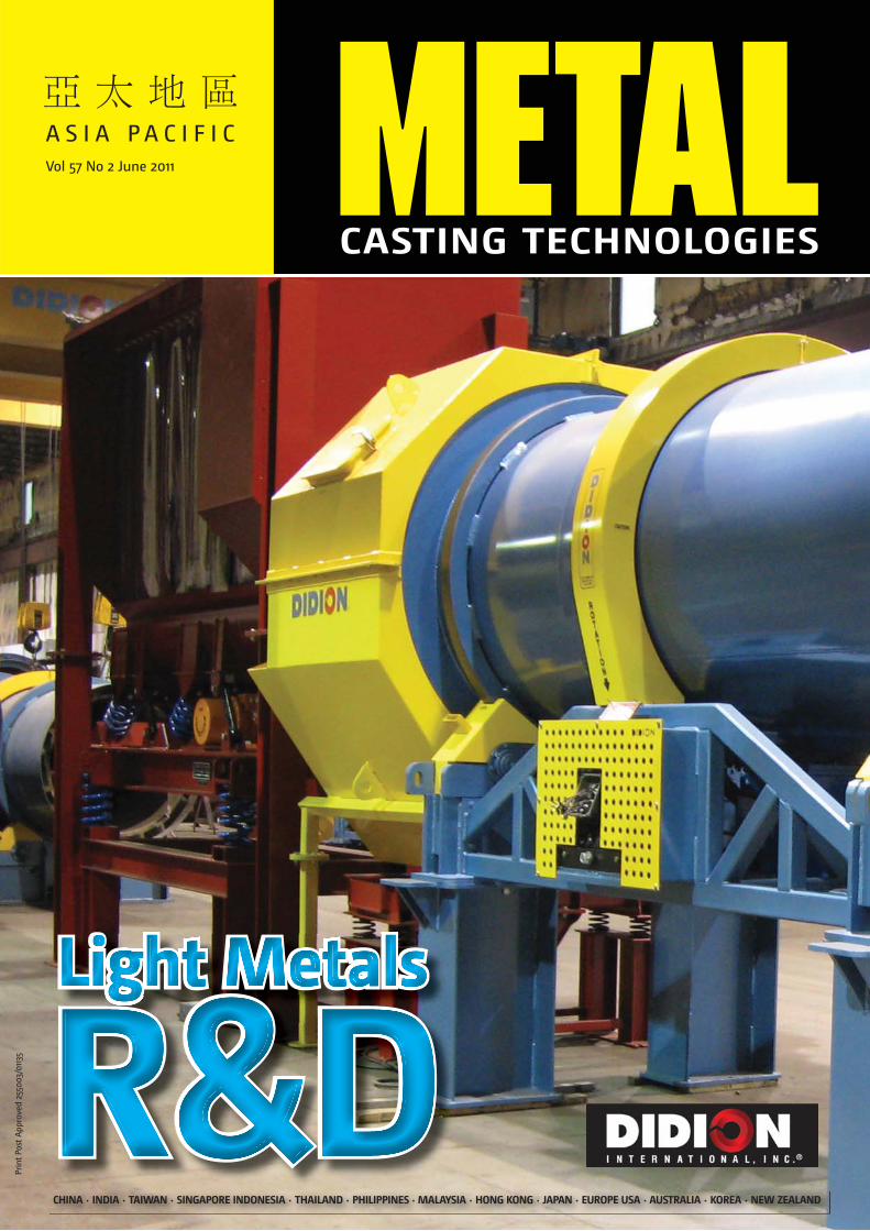
Front Cover: Didion International IncRotary Separator/Metal Reclaimer with variable jet burner to remove moisture.For further information see pages 4 and 5
ADVERTISER’S INDEXAccess Environmental Systems (Coolfog) ...... 29AFI National Conference (Queenstown NZ) .... 33Ajax Tocco Magnethermic .................................... 35Aluminium Cast House Technology .............. IBCBeckwith Macbro Sands ......................................... 31Didion International Inc ............................. OFC/4-5Finite Solutions Inc .............................................. 8-9Foseco ...................................................................... OBCFurnace Engineering ................................................. 3G&C Instrument Services ................................. 39/41General Kinematics .................................................. 25IMF .................................................................................. 15Inductotherm .............................................................. 11Magma Engineering Asia Pacifi c ........................ 23Morgan Molten Metal Systems ........................... 17Sibelco ..................................................................... 19/21Spectro Analytical Instruments GmbH .............. 13Synchro 32 ................................................................... 27Warill Engineering Sales (Aust) ......................... IFC
Furnace Engineering offers the following capabilities:
Increase Efficiencies, Safety and Environmental Standards
Furnace Engineering Pty Ltd
Leaders in Heat Processing SolutionsQuality ISO 9001
50 Howleys Road, Notting Hill VIC 3168 Email [email protected]/14 Welder Road, Seven Hills NSW 2147 www.furnace.com.au
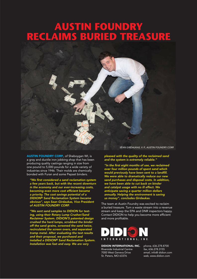
AUSTIN FOUNDRY CORP., of Sheboygan WI, is a gray and ductile iron jobbing shop that has been producing quality castings ranging in size from one pound to 5,000 pounds for a wide variety of industries since 1946. Their molds are chemically bonded with Furan and some Pepset binders.
“We first considered a sand reclamation system a few years back, but with the recent downturn in the economy and our ever-increasing costs, becoming even more cost efficient became a priority. The cost savings potential of a DIDION® Sand Reclamation System became obvious”, says Sean Girdaukas, Vice President of AUSTIN FOUNDRY CORP.
“We sent sand samples to DIDION for test-ing, using their Rotary Lump Crusher/Sand Reclaimer System. DIDION’S patented design crushed the hard lumps, scrubbed the binder off the sand grains, screened the sand twice, recirculated the screen overs, and separated tramp metal. After evaluating the test results and their proposal, we purchased and installed a DIDION® Sand Reclamation System. Installation was fast and easy. We are very
pleased with the quality of the reclaimed sand and the system is extremely reliable.”
“In the first eight months of use, we reclaimed over four million pounds of spent sand which would previously have been sent to a landfill. We were able to dramatically reduce our new sand purchases and disposal costs. In addition, we have been able to cut back on binder and catalyst usage with no ill effect. We anticipate saving a quarter million dollars annually. Helping the environment is saving us money”, concludes Girdaukas.
The team at Austin Foundry was excited to reclaim a buried treasure. Turn a waste stream into a revenue stream and keep the EPA and DNR inspectors happy. Contact DIDION to help you become more efficient and more profitable.
DIDION INTERNATIONAL INC.Riverside lndustrial Centre7000 West Geneva DriveSt. Peters, MO 63376
phone, 636.278.8700fax, 636.278.3155email, info@ didion.comweb, www.didion.com
AUSTIN FOUNDRY RECLAIMS BURIED TREASURE
SEAN GIRDAUKAS, V. P., AUSTIN FOUNDRY CORP.

ADVANTAGES AND FEATURES✔ Patented multi-chamber design combines lump crushing, sand scrubbing, sand conditioning, dual sand screening, and metal separation for the fastest payback.✔ The time-tested design has the best performance/highest yield (up to 97%) in the industry.✔ Significant savings from reduced binder consumption, lower new sand purchases, and minimal disposal costs.✔ Additional savings from conditioned and higher quality reclaimed sand (which is more uniform/consistent) lowers finishing costs and reduces casting scrap.✔ The patented design has the lowest operating cost per ton in the industry worldwide, with system sizes from 1-100 TPH✔ Highly efficient air-wash separation removes binder, dust, debris, and excess fines.✔ Continuous improvement and development have made us the world leader in sand reclamation.
Intake end
High quality reclaimed sand
Reclaimed clean tramp metal
Concise clean system
SEAN GIRDAUKAS, V. P., AUSTIN FOUNDRY CORP.
Reclaim your buried treasure – contact DIDION.
DIDION INTERNATIONAL INC.Riverside lndustrial Centre7000 West Geneva DriveSt. Peters, MO 63376
phone, 636.278.8700fax, 636.278.3155email, info@ didion.comweb, www.didion.com

6 www.metals.rala.com.au
Staying alert
oday it is so difficult to run with the speed of the market. While the whole world is coming closer due to the advancement in constant, overall technologies, the same
prevails with metal casting technologies. It is therefore essential to remain alert to what is the latest technology, as it applies to you, and in terms of its application and profitable use. In this edition of Metals magazine we have brought you a technical paper by Martin Prekel and Carlos H. Caceres who talk about light alloys, energy sources and the overall transport industry.
It is now normal to read and speak about energy efficiencies and environmentally sustainable foundry practices and to this end we also bring you a technical paper on the foundry sand binder which will also deepen your knowledge of this technology.
We all know and accept that globalisation will remain a constant for the auto industry. From now on it comes with a built-in expectation of addressing the demand for environment-friendliness, lighter weights and shorter delivery times and it must be with the use of the latest materials and units. Backing this will have to be much focused research and development to include close co-ordination with customers – the market. And auto vehicles are increasingly part of
the “must haves” of the rising middle class in India and China. So the “green” mantra will also increase.
Since our last edition, the troubles and uprisings in the Middle East have focused our attention. We all hope that democracy will ultimately prevail. But business does not like uncertainty and as this area is one of the primary sources of oil supply, the world’s car manufacturers know that the winds of change are increasing. And not likely to abate anytime soon. The West is extremely dependent on oil and to with-hold or manipulate supplies is an enormous power
over world markets. The West is car dependent, particularly the US, increasingly China, Japan and Asia generally. Some argue that we reached peak oil two years ago. But whatever the reality of oil status, we must reduce our dependency on it. Apart from overall general industry requiring oil to drive it, cars are the next biggest consumers. For many years now we all have been fully aware of the pivotal role of oil and it has driven the escalation of R&D for technology to replace it in cars. It has spawned the EV market.
While the EV market is being driven with as much speed as possible, General Motors Corp, also with full awareness of the demand for fuel
Barbara Cail
CON
TRIB
UTO
RS EDITORIAL
T
JOHN HERMES D. BAUTISTAPMAI Technical Consultant
DR. P. C. MAITYDr. P. C. Maity, Metal Casting and Materials Engineer
GOPAL PADKIGopal Padki is a senior executive member of HA in China. HA is committed to green, environment and energy efficient processes for the best performance of foundries worldwide.
JEFF F. MEREDITHCasting Solutions Pty Ltd
JOHN PEARCEMetals Specialist, MTEC National Metals and Materials Technology Centre, Thailand

efficient cars, is investing a total of $96 million at two of its GM Powertrain division’s metal casting operation, to install new tooling and equipment for its current and future engine packages. The foundries at Bedford, Ind., and Defiance, Ohio, are among 17 GM plants to share in a $2-billion capital improvement program that the automaker announced last month. $49 million is earmarked for new tooling and equipment to produce components for an eight-speed transmission which will improve fuel economy in a number of future vehicles and a new gasoline engine, which will be offered in displacements from 1.0 litres to 1.5 litres. They believe this will be the key to fuel economy leadership in the small four-cylinder engine segment.
It will be interesting to watch the emerging profile of car engines in the next five years. It is essential that metal casters keep fully informed of all the movements in the huge enterprise – the car industry. As mentioned, EV’s are powering along and taking up their market position.
However, the issue of battery technology has yet to be refined before EV’s reach a fully competitive position. MIT researchers have come up with a radically new approach to battery design which utilises an architecture called semi-flow cell, in which solid particles are suspended in a carrier liquid and pumped through the systems. The positive and negative electrodes (cathodes and anodes) are composed of particles suspended in liquid electrolyte. The two different suspensions are pumped through systems separated by a filter – a thin porous membrane. This enables the spent liquid to be pumped out quickly and refilled: an echo of the petrol station.
We will go on listening to the constant siren call of “green” and “economy”. Apparently there is only about 15% of the energy from the fuel put into the traditional petrol engine which gets used to move a car down the road or run useful accessories, such as air conditioning. The rest of the energy is lost to engine and driveline inefficiencies and idling. Therefore, the potential to improve fuel efficiency with advanced technologies is enormous. This is why the world is moving to lighter vehicle bodies, higher-performance electrical components, and enhanced fuel economy. This will drive the necessary, and possibly, urgent need for high technical development capacity to address the increasingly diversified needs of electric vehicles, hybrid electric vehicles, next-generation internal-combustion cars, and other products in raising the level of environmental performance in motor vehicles.
I hope you enjoy deepening your knowledge base with what we have delivered to you in this edition.
Barbara Cail
WHO’S WHO OF METALS ANNUAL BUYER’S GUIDE
METAL Casting Technologies June 2011 7
BOOK NOW FOR BEST POSITIONINGContact Adam Cail Ph: +61 2 9555 1944or email [email protected]
SEPTEMBER 2011 – Who’s Who of Metals
Including Annual Buyer’s Guide
Editorial deadline: 3 August
Advertising booking deadline: 10 August
Material deadline: 24 August
NEXT ISSUE
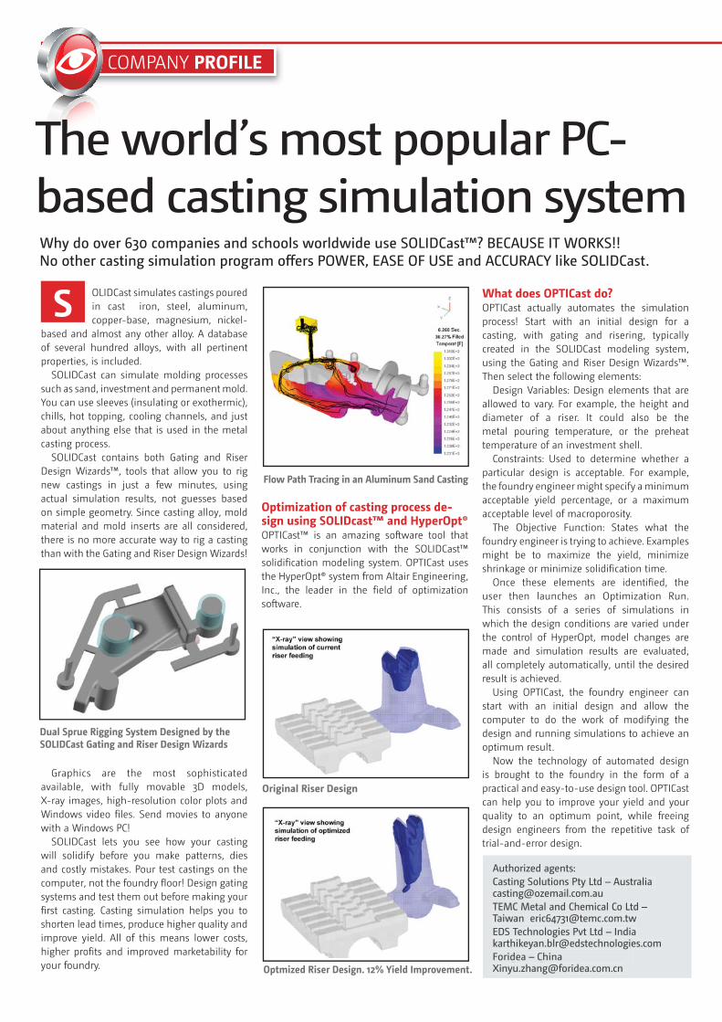
COMPANY PROFILE
OLIDCast simulates castings poured in cast iron, steel, aluminum, copper-base, magnesium, nickel-
based and almost any other alloy. A database of several hundred alloys, with all pertinent properties, is included.
SOLIDCast can simulate molding processes such as sand, investment and permanent mold. You can use sleeves (insulating or exothermic), chills, hot topping, cooling channels, and just about anything else that is used in the metal casting process.
SOLIDCast contains both Gating and Riser Design Wizards™, tools that allow you to rig new castings in just a few minutes, using actual simulation results, not guesses based on simple geometry. Since casting alloy, mold material and mold inserts are all considered, there is no more accurate way to rig a casting than with the Gating and Riser Design Wizards!
Graphics are the most sophisticated available, with fully movable 3D models, X-ray images, high-resolution color plots and Windows video files. Send movies to anyone with a Windows PC!
SOLIDCast lets you see how your casting will solidify before you make patterns, dies and costly mistakes. Pour test castings on the computer, not the foundry floor! Design gating systems and test them out before making your first casting. Casting simulation helps you to shorten lead times, produce higher quality and improve yield. All of this means lower costs, higher profits and improved marketability for your foundry.
Optimization of casting process de-sign using SOLIDcast™ and HyperOpt®OPTICast™ is an amazing software tool that works in conjunction with the SOLIDCast™ solidification modeling system. OPTICast uses the HyperOpt® system from Altair Engineering, Inc., the leader in the field of optimization software.
What does OPTICast do?OPTICast actually automates the simulation process! Start with an initial design for a casting, with gating and risering, typically created in the SOLIDCast modeling system, using the Gating and Riser Design Wizards™. Then select the following elements:
Design Variables: Design elements that are allowed to vary. For example, the height and diameter of a riser. It could also be the metal pouring temperature, or the preheat temperature of an investment shell.
Constraints: Used to determine whether a particular design is acceptable. For example, the foundry engineer might specify a minimum acceptable yield percentage, or a maximum acceptable level of macroporosity.
The Objective Function: States what the foundry engineer is trying to achieve. Examples might be to maximize the yield, minimize shrinkage or minimize solidification time.
Once these elements are identified, the user then launches an Optimization Run. This consists of a series of simulations in which the design conditions are varied under the control of HyperOpt, model changes are made and simulation results are evaluated, all completely automatically, until the desired result is achieved.
Using OPTICast, the foundry engineer can start with an initial design and allow the computer to do the work of modifying the design and running simulations to achieve an optimum result.
Now the technology of automated design is brought to the foundry in the form of a practical and easy-to-use design tool. OPTICast can help you to improve your yield and your quality to an optimum point, while freeing design engineers from the repetitive task of trial-and-error design.
Authorized agents:Casting Solutions Pty Ltd – Australia [email protected] Metal and Chemical Co Ltd – Taiwan [email protected] Technologies Pvt Ltd – India [email protected] Fdy Tech Co Ltde.com.cn
The world’s most popular PC-based casting simulation system
S
Why do companies and schools worldwide use SOLIDCast™? BECAUSE IT WORKS!! No other casting simulation program offers POWER, EASE OF USE and ACCURACY like SOLIDCast.
Dual Sprue Rigging System Designed by the SOLIDCast Gating and Riser Design Wizards
Original Riser Design
Optmized Riser Design. 12% Yield Improvement.
Flow Path Tracing in an Aluminum Sand Casting
Authorized agents:Casting Solutions Pty Ltd – Australia [email protected] Metal and Chemical Co Ltd – Taiwan [email protected] Technologies Pvt Ltd – India [email protected]
.com.cn

COMPANY PROFILE
Why Use Casting Simulation From
FSI?Largest User Base in the World
Easiest to Use
Fastest Results
Integrated Gating and Riser Design
Lowest Cost to
Solidification Analysis
Buy and Use
Flexible Payment Plans Available
Multiple Language Versions
World Wide Support
www.finitesolutions.com
Casting simulation for the working foundry
Mold Filling
Feeding Zone Analysis for Riser Design
Visit us at GIFA stand 15/G10.

10 www.metals.rala.com.au
BRIEFINGS
Australia and India join automotive strengthsSMR Automotive Australia, an Indian-owned, South Australian-based company and the Australian Government has joined forces to create new Australian jobs, skills and products, through the design and production of world-leading lightweight mirrors for cars.
SMR Automotive has received a $2.4 million grant from the Green Car Innovation Fund to set up a pilot plant in Adelaide to adapt leading-edge technology to manufacture the mirrors.
At its new facility, SMR will develop lighter mirrors that will reduce the mass compared with current mirrors, leading to a reduction in carbon dioxide emissions by vehicles fitted with the new mirrors. The company estimates that if the pilot project leads to full production, its mirrors will save about 400,000 tonnes of carbon dioxide emissions over five years. SMR employs over 600 people and produces mirrors for locally made cars and exports many more to leading auto companies around the world.
Parts shortage from Japan slows Thai industryMany manufacturers in Thailand, especially in the automotive sector, depend on supplies of important parts from Japan. Due to effects of the earthquake and tsunami disaster on Japan’s industrial production this supply has been considerably reduced such that, in the current year, the output from the Thai auto industry is expected to fall by around 150,000 vehicles. The main area of shortage is for electronic parts. All the Japanese joint venture auto assembly plants have been working at reduced capacity since mid-April. For example, Toyota has cut production by up to 70% at its three Thai plants, with Isuzu and Honda cutting by up to 50%. Overall production levels during April to June are expected to be halved. At present the auto plants are retaining production workers on a normal
timetable by carrying out training and plant maintenance in readiness for the return to full production but workers may have to be laid off in the longer term if shortages persist. Because of these cutbacks Thai auto-parts producers have also had to reduce their production levels to avoid excessive build up of stocks, although the larger auto iron-foundries are expecting to resume full production by July.
In spite of these cutbacks and other economic and energy cost concerns a record number of visitors is expected to attend the forthcoming “Manufacturing Expo 2011” to held during 23rd - 26th June at BITEC in Bangkok. Geared to the manufacturing and supporting industries this event consists of four exhibitions, namely “InterPlas” (rubber and plastics), “InterMold” (dies and mould making), “Assembly Technology” (manufacturing systems and automation) and “Automotive Manufacturing” (vehicle and motorcycle parts and technology). A number of industrial organizations including the Thai Foundry Association will be holding seminar sessions during the expo. (Further information is at www.automanexpo.com).
Global car component deal helped by CSIRO technologiesAccess to a portfolio of cost-competitive CSIRO casting technologies was crucial to Nissan Casting Australia’s (NCAP’s) recent successful bid to manufacture components for the Nissan Motor Company’s new LEAF electric car in Dandenong, Victoria, Australia.
“NCAP’s access to CSIRO’s advanced casting technology, which offers significant potential future savings, was instrumental to our winning the contract,” said NCAP’s business development and corporate planning manager, Brian Cooper.
Technologies jointly developed by CSIRO and NCAP through the CAST CRC will be implemented as part of the Australian Government’s recently announced $21 million investment in
sustainable, zero-emission technologies.Brian Cooper says that , “Support
for 145 Victorian manufacturing jobs in the highly competitive international automotive industry is a great outcome, and CSIRO is delighted to have contributed to it”
$40m grant for a ‘Greener’ CommodoreUsing a $39.8 million Green Car Innovation Fund grant, Holden will transform the way they design, engineer and manufacture the Commodore — Australia’s top-selling large car — reducing fuel consumption by more than 7 per cent.
This fuel consumption equates to an average of 3.6 million litres per year — and an average cut of 9,000 tonnes of emissions — from the Australian Commodore fleet.
Innovation Minister Senator Kim Carr said environmental and economic benefits would flow from Holden’s innovation through reduced carbon emissions, increased employment and skills, and far-reaching commercial opportunities.
“Production of the new Commodore will contribute $1.13 billion in wages to the Australian economy over the life of this project and inject $420 million into the local components industry each year,” Senator Carr said.
“The research and development and technology advancement behind this project are vital to the future of Holden and its workers, complementing the localisedCruze launched earlier this year.”
This Commonwealth investment in partnership with GMH will help produce a better Australian made car. This includes reducing the weight of the car by using aluminium body panels. Holden will also look at ways to increase the aerodynamic performance of the Commodore.
For more information on the New Car Plan, visit www.innovation.gov.au, www.ausindustry.gov.au, phone 13 28 46, or email [email protected]

Who will invest in developing the advanced technology you need to stay competitive?
Inductotherm Group: Many companies.
One mission. To design and manufacture the most
advanced thermal processing systems to help your
company succeed. No matter what metal you melt,
heat treat, hot forge or process, the Inductotherm
Group will put our shared knowledge, global
reach and unparalleled technology to work for
one company. Yours.
INDUCTOTHERMGROUP.COM
WILL.
Visit us at H ll 10
THE MASTERS OF HIGH QUALITY MELTING & HEATING
SERVICE 24 HOURS/DAY - 7 DAYS/WEEK Tel: 61 3 9786 7000
Talk to Inductotherm’s Heating and Melting Systems Specialists for all your Forging, Heat Treatment, Brazing, Melting and Automatic Pouring (in Air, Vacuum or Inert Atmospheres).
Retain your competitive edge. Call Inductotherm now …
LOCAL CONTACT: INDUCTOTHERM PTY LTD 62 Bardia Ave Seaford Victoria 3198 Australia Tel: 61 3 9786 6000, Email: [email protected] Internet: www.inductotherm.com.au
Visit us a
t
Thermpro
cess/GIF
A
Hall 10, S
tand 1
0B24
Dusseldorf,
GermanyVisit
us at
Visit us a
t
Visit us a
tAA
Thermpro
cess/GIF
AA
Thermpro
cess/GIF
A
Hall 10, S
tand 1
0B24
Hall 10, S
tand 1
0B24
Hall 10, S
tand 1
0B24
June 28th
- July 2
nd
June 28th
- July 2
nd
June 28th
- July 2
nd
Dusseldorf,
Germany
Dusseldorf,
Germany
Dusseldorf,
Germany
Leading Manufacturers of Melting, Thermal Processing and Production Systems for the Metals and Materials Industry Worldwide

12 www.metals.rala.com.au
BRIEFINGS
AFS Casting of the Year Awards The metalcasting industry recognized nine cast components as top designs for the 2011 American Foundry Society/Metal Casting Design & Purchasing Casting Competition. The components are used in a variety of industries, including automotive, construction, agriculture and military.
Lethbridge Iron Works Co. Ltd., Lethbridge, Canada, and Eck Industries, Manitowoc, Wis., earned top honours in the annual competition for their Front Cab Support Bracket designed to support the cab of a Daimler Western Star model truck. The green sand casting has been redesigned several times over the years to meet changing packaging requirements. For the latest redesign, Daimler worked closely with Lethbridge to consolidate an assembly of three castings, seven welded assemblies and 16 low-level parts into two castings, zero welded assemblies and four low-level parts.
Lethbridge’s ductile iron component weighs 35.3 lbs. and measures 18 x 16 x
9 in. Converting the front cab support bracket from a weldment delivered the customer a 22% weight savings and 35% cost savings per vehicle.
Eck’s Hybrid H40/50 EP System Stator Housing holds the two-mode parallel stator assembly used in Allison Transmission’s H40/50 EP hybrid system. The casting is a complex aluminium design that offers tight concentricity tolerances across multiple large core assemblies, multiple cast-in features, zero-porosity and no-leak customer requirements.
The aluminium part weighs 116 lbs., measures 18 x 18 x 21 in. and was produced using the no bake process with low pressure mould filling. It was previously a fabrication.
AFS and Metal Casting Design & Purchasing also awarded four Best-in-Class honours and three Honourable mentions.
2011 Best in ClassLower Connector, by Piad Precision Casting, Greensburg, Pa. The metalcaster’s C011 alloy was selected because it is a pure electrolytic copper with a minimum electrical conductivity of 98%. The as-cast weight of the part was 25% greater than any part the metalcaster produces, and it includes 15 heat-dissipating fins, four cast-in elongated slots for air flow, a cast hole machined to accept mating parts, three cast mounting surfaces and a large cast diameter on one end, which is machined to accept a mating connector.
Auxiliary Drive Casting, by ThyssenKrupp Waupaca, Waupaca, Wis. The part offered the customer a cost reduction, simplified assembly and reduced inventory costs. It was integral to the success of the customer’s engine build, as it accommodated limited space and weight restrictions. To make the component castable, design changes were required to the 170-lb. John Deere tractor engine auxiliary drive casting due to challenging geometry. The casting avoided the need for multiple cast, fabricated and/or welded parts.
Exhaust Manifold, by Stahl Specialty Co., Kingsville, Mo. The component was converted from a two-piece design, eliminating a gasket and potential leak and saved 38 lbs. per engine. The new design reduced emissions and increased power output by 6%. The design required the component’s water jacket and exhaust cores be nested on each other without core prints to locate them on the mold. The core positions relative to each other presented a major challenge for ensuring minimum wall and water jacket thicknesses.
Timing Gear Cover, by Grede II LLC, Columbiana, Ala. The casting reduced costs by eliminating bolt-on components and reduced weight by eliminating unnecessary mass and reducting draft. The casting incorporates a water pump component, EGR passage and coolant return passage (all with no cores required), idler pulley mounting pedestal
and alternator mounting bracket (eliminating additional components), washer face and various cast passages and openings.
2011 Honourable MentionRifle Scope Body Casting, by Ti Squared Technologies, Sweet Home, Ore. The near-net-shape titanium casting reduced manufacturing costs by 20% by eliminating machining.
PV524 Fire Pot, by Tonkawa Foundry Inc., Tonkawa, Okla. The part, which was the customer’s first conversion to casting from a fabrication, saved $50,000 per year and considerable fabrication time.
Headlight Subassembly and LED Mounts, by ODC Manufacturing Ltd., Barrie, Canada. The casting supplier recommended the customer consider a plastic design for the part, but the automotive company needed the mounts to act as a heat sink. The customer required that all critical features were cast into the mounting frame and that an accurate LED bulb angle was achieved for all seven bulbs.
This year’s Casting Competition was sponsored by Magma Foundry Technologies, Schaumburg, Ill. Magma will provide Lethbridge Iron Works and Eck Industries with a one-year license of Magmasoft software, including training and implementation assistance.
Electric bikes claim bigger slice of Asian marketThe Asian market is now the biggest in the world for electrical bicycles. At the beginning of 2010, there are around 120 million ‘e-bikes’ in China with annual sales more than US$11 billion. At the same time production of non-electrical bicycles, has fallen by more than 25%. Targeting ChinaThere is an increasing need for environmentally friendly and clean products Adjustments and regulations made by the Chinese government

On-site, at-line and in the laboratory - from SPECTRO and its metal analyzers you can expect:- Perfect analysis solutions with innovative technologies - Fast and precise measurements, plus ease of use and reliability- Outstanding performance and flexibility- Comprehensive service and analytical expertise of the market leader- Unrivaled price-to-performance-ratio
Talk with SPECTRO and find out why SPECTRO‘s metal analyzers are an investment in better efficiency and higher profitability.
Tel. +852.2976.9162 Fax [email protected] www.spectro.com
Metal
Analysis
with SPECTRO
Analyzers

14 www.metals.rala.com.au
in the electric bicycle industry is designed to encourage the use of electrical bicycles by banning petrol-fuelled scooters in some parts of the country and encouraging the application of lighter materials in their manufacture.Faster and lighterSpokesperson for the Höganäs company which is specifically manufacturing e-bikes for the China market says that the new motor they are creating has a number of benefits over previous models. They use metal powder which gives their engine a lower weight and more compact design. “It is lighter than other electric motors and in the e-bike it has a good range, up to 75 km,” Höganäs Group CEO Alrik Danielson said. The previous motor, designed by Newcastle University, could reach only up to 20 km, and was around twice the weight.
The motor is easy to assemble making it suitable for large scale, highly automated manufacturing. The motor is also suitable for other applications besides electric bicycles such as electric scooters, other light electric vehicles, fans, pumps and generators, because it is compatible with standard BLDC controllers. The Somaloy material is based on surface coated iron powder particles that have 3D magnetic flux properties. This enables more design flexibility and the motor can be designed for the specific application.
The design is developed to decrease the environmental impact. The start or is based on metal powder manufactured from melted metal scrap which pulverizes it with high-pressure gas or liquid, and the motor design can be then be easily recycled due to the easy separation of parts. It uses fewer rare earth magnets and copper wire than comparable conventional electric motors, due to the electromagnetic design of the motor.
Japan to finance quake-hit car parts makers
Japan’s government-owned bank is planning to set up a 50 billion yen ($617 million dollar) fund to support auto parts makers hit by the March 11 quake and tsunami.
The Development Bank of Japan will launch the fund this month, and will be asking major commercial banks for investment. The great disaster caused by the tsunami seriously damaged supply chains of auto parts makers, and financial support is needed.
It is understood that under the plan, the bank will offer the investment to the Japan Auto Parts Industries Association, which will then provide cash for its member firms as well as their subcontractors.
Japan has 800 major auto parts manufacturers supplying interior equipment and parts such as air conditioners to the nation’s automakers.
Under these major auto parts makers, there are some 4,000 subcontractors and 20,000 sub-subcontractors, according to local media.
Japanese auto giants Toyota and Honda saw global production halved in April as the disaster ravaged supply chains.
The quake and the resulting tsunami shattered component supply chains and crippled electricity-generating facilities, including a nuclear power plant at the centre of an ongoing atomic emergency.
Amid power and parts shortages, Toyota had announced production disruptions domestically and in the United States, Europe, China and Australia because of the crisis, temporarily slowing output or shutting plants.
Many component manufacturers that are key to auto production are based in the worst-hit regions of Japan, their facilities damaged by the 9.0 magnitude earthquake or inundated by the giant wave that followed.
While most plants resumed
production by mid-April, operations remain well below capacity and analysts warn parts shortages could go on for months, with the threat of summer power shortages also casting a shadow over the economy.
New team member for Synchro
Jean-Marie Darchicounrt has joined the Synchro team as Partnership/Agent Liaison Manager. The focus for this newly created position will develop the expansion of a partnering and agency program. The expansion of the company and the development of new markets, responding to global opportunity will take Synchro to an unprecedented level of growth.
Jean – Marie has over a decade of experience with Synchro32 with group implementations including several in China. Well versed in the practical day-to-day use of the Synchro32 software, sensitive to customer expectations and business requirements with strong focus on project management.
Jean-Marie brings to Synchro years of experience in the steel and rolled goods manufacturing industries ranging from software implementation, IT and a strong emphasis on project management. In addition he has extensive knowledge in Quality ISO 9002 procedures and Lean Manufacturing.
He will build a strategic frame for the creation of a successful partnering program. ■
BRIEFINGS
Jean-Marie Darchicounrt

ww
w.r
p2.it
I.M.F. srlVia Turati 110/121016 Luino (VA)-ItalyTel. +39 0332 542424Fax +39 0332 542626e-mail: [email protected]
www.imf.it
We complete your knowledge
Complete No-Bake moulding linesRobotic centers for core productionShotblasting and shotpeening plants
GROUP
KOREA - LUXEMBURG - MESSICO - MAROCCO - ALGERIA - TUNISIA - NETHERLAND - NORWAY - POLAND - ROMANIA - RUSSIA - BIELORUSSIA - UKRAINA - SPAIN - PORTUGAL - SWEEDEN - SWITZERLAND - TAIWAN - THAILAND - TURKEY - U.S.A. - VIETNAM
AUSTRALIA - BELGIUM - BRAZIL - ARGENTINA - CHILE - CHINA - CZECH REPUBLIC - REP. OF CONGO - DENMARK - FINLAND - FRANCE - GERMANY - GREAT BRITAIN - GREECE - INDIA - UNITED ARAB EMIRATES - INDONESIA - ISRAEL - ITALY - JAPAN
GIFA June 28 - July 2STAND 15G38

16 www.metals.rala.com.au
TECHNICAL FEATURE
Abstracthe environmental feasibility of light (aluminium and magnesium) alloy substitutions for cast iron and steel components in freight trains and passenger cars is
compared using a fleet based life cycle assessment. The time to offset the production emissions of the primary Al and Mg metals via the increased fuel efficiency due to the vehicles’ mass reduction is much shorter for substitutions involving castings than for those involving the wrought alloys in both trains and cars, but the higher fuel efficiency of the formers results in longer crossover times in all cases. The use of low emission energy sources for the electrolytic production of the primary metals is a necessary condition to the environmental feasibility of any light alloy substitution. The current extensive use of the Pidgeon method is a major liability for all Mg alloy applications.
IntroductionLight alloy (aluminium and magnesium) substitutions for heavier iron and steel components in both automotive and railway applications date back to the late 19th century; however, in recent decades much larger quantities of light metals are being used in all sorts of vehicle construction to increase performance (increased fuel efficiency for automobiles and higher speeds, larger payloads and reduced wear of the tracks for trains), hence lowering both ongoing costs and CO2 emissions [1].
The two major drawbacks to light metal substitutions stem from their higher cost and the amount of energy required to produce the primary base metal in comparison with traditional ferrous materials (and as such, higher expenses and initially greater environmental impact through CO2 emissions). Both, the financial and initial energy burdens, must be offset by the resulting reduced fuel consumption and/or increased pay load in a reasonably small fraction of the vehicle’s service life for the substitutions to be feasible [2-5].
The production of either aluminium or magnesium is an extremely energy intensive process. When electrolysis is used, which is the case for all of the aluminium and a fraction of the magnesium, the dominant factor is that of the energy source of electricity. A point in case is that of Australia’s aluminium smelters, which are among the most polluting in the world due to the
almost complete reliance on fossil fuel derived electricity; however if electricity could be produced from sources with low carbon emissions, i.e., nuclear, hydro or geothermal, the production emissions would decrease dramatically, and the benefits would propagate downstream onto transportation [2]. Magnesium represents a special case, as the highly polluting Pidgeon method [5, 6], used largely in China, is currently prevalent as a production method due to its lower costs. By necessity then, any lifecycle analysis of material substitutions must explicitly involve the eventual substitution of primary energy sources and/or production methods as well.
The main purpose of this paper is to calculate how long it would take for a fleet of freight trains to off-set the initially greater emissions involved in the production of the light alloys used to lighten up the cars and compare the results with equivalent data for a fleet of family sedans. The analysis of the financial burden will be left out for simplicity; a detailed study applied to the automobiles can be found elsewhere [3].
The two case studies to be compared, family cars and freight trains, represent extreme examples of low (cars) and high (trains) fuel efficiency. Thus the results can be considered as upper and lower bounds to the feasibility of light alloy substitutions aimed at increasing fuel efficiency. Low and high emissions energy sources are also considered in the analysis. A life cycle assessment (LCA) method derived from Field et al. work [4] will be used, with explicit consideration of the mechanical functionality of components through the application of Materials Indices and Exchange Constants [2, 3].
Materials indices for mass and CO2 emissions reductionA substitution must preserve the functional performance of the original component in order not to alter the vehicle’s behaviour under operation. To simplify the analysis, the possible substitutions have been sorted into three generic categories: beams, panels and castings. For the two former ones, the substitutions must have the same stiffness and/or strength whereas for castings the replacement is assumed at equal volume. Stiffness considerations usually lead to heavier components that those based on strength [2, 3], so the latter need not be considered in a first analysis.
Light alloys, energy sources, and the transport industryMartin Prekel, Carlos H. Cáceres- Materials Engineering, School of Engineering, The University of Queensland, QLD-4072, Australia
T

TOMORROW’S SOLUTIONS…TODAY
欢迎在6月28号 至 7月2号举行的德国GIFA展会期间前来参观我们的展位,11号展厅#J131展位。
摩根熔铸系统, 有色金属熔炼坩埚的全球行业领导者。 我们创新的目标简单明确,达到的成效却无与伦比。
帮助您实现: 最高品质的金属熔炼 提高产出率(更多使用炉次) 坩埚品种在行业内最多最全, 方便您挑选出性价比最佳的产品
Morgan Molten Metal Systems is the global leader in the supply of crucibles to the non-ferrous
metals industry. Our goals are simple. Our results unparalleled.
Helping you:
range of products
Visit us at GIFA, June 28-July 2, Hall 11 #J131
Come see the Z2 Syncarb, our energy
effi cient crucible for higher temperature
applications. Only from MorganMMS.
创新明天的解决方案⋯今天

TECHNICAL FEATURE
Material indicesallow for a straightforward ranking of the substitution’s efficiency, in terms of mass reduction for given mechanical performance, through Eq. 1:
(1)
where m1 and m2 are the masses of the incumbent and replacement component and M1 and M2 the respective materials indices. By way of an example, for castings, using the material indices of Table 1, M1 = 1/ρ1 and M2 = 1/ρ2 equation 1 becomes
(1-a)
Table 2 shows that using a Mg alloy casting decreases the mass of a similar cast iron component by 75%, whereas Al only does it by 62%. For panels and beams, the mass efficiency of the substitution is somewhat less, at between 40 and 60%, due to the lower elastic modulus of the light metals. Derivations of material indices involving mechanical, environmental and other applications can be found in reference [7].
Substituting cast iron or steel by Al or Mg to reduce mass conveys an upfront environmental penalty stemming from the larger CO2 footprint attached to the production of the primary light metals. The trade-off between mass and CO2 footprint involved in the substitution can be expressed as an exchange constant, β, defined by equation 2,
(2)
where the l indicates litres of gasoline, ΔCO2 burden is the difference in CO2 content (measured in gasoline equivalent units) between the incumbent and the light metal component, and Δ mass is the difference in the respective masses while maintaining the structural performance unchanged. The gasoline equivalent CO2 content was calculated assuming that the burning of one litre of gasoline creates [2, 3] 2.85 kg of CO2. The small difference in CO2 content per litre between the diesel fuel used by trains and the gasoline used by cars has been ignored.
Table 3 summarises the β values for the best (low CO2
electricity, e.g., from nuclear or hydroelectric sources) and worst (high CO2 electricity from fossil fuels) environmental cases, and assuming the maximum recycling rates for each of the respective metals [2, 3]. Note that the β values of Table 3 apply to both passenger cars and trains.
18 www.metals.rala.com.au
Table 1. Material indices (M) for substitutions involving mass and gasoline equivalent footprint reductions. (hg is a the amount of CO2 created during the production of 1 kg of primary metal, measured in litres of gasoline [2,3].)
Table 3. The exchange constants, β, (in litres of gasoline per kg of mass reduction, l/kg) for low and high emissions energy sources [2, 3]. Cast iron or steel (Fe) are substituted by either Aluminium (Al), electrolytic Magnesium (Mg) or Pidgeon Magnesium (Mg*) components. For Al and Mg castings a recycling rate of 60% and 35% was assumed, respectively, whereas for the wrought alloys used in beams and panels, the assumed recycling rate was 8% for Al and nil for Mg [3].
Table 2 . Material properties and relative mass of components (beams and panels of the same stiffness, and of castings of similar volume, as those of a ferrous component) made of either Al or Mg alloys. Calculated using Eq. (1) assuming an incumbent component made or either cast iron or steel, of mass 10 kg.
Δ CO2 burden
Δ mass
Mass Gasoline Equivalent CO2 emissions
Castings ρ-1 (ρhg)-1
Beams
Panels
E(GPa)
ρ(Mg/m3)
Beam(kg)
Panel(kg)
Cast(kg)
Iron 115 7.2 - - 10
Steel 210 7.8 10 10 -
Al 75 2.7 5.8 4.9 3.8
Mg 44 1.8 5 3.9 2.5
High CO2 β Casting β Panel β Beam
Fe ➝ Al 1.9 4.2 6.5
Fe ➝ Mg 4.5 6.5 11
Fe ➝ Mg* 4.8 8.9 14
Low CO2
Fe ➝ Al 0.2 0.3 1.5
Fe ➝ Mg 0.6 1.4 2.5
Fe ➝ Mg* 3.8 6.9 11

Trust your most complex cores to INCAST ®. The idealcombination of geometry, density and particle size distribution, INCAST improves critical core making and casting propertiesincluding binder utilization, permeability and dimensional stability. Higher strength cores, better surface finish and increased efficiency and yield are the INCAST advantages.These sands are engineered for the metalcaster.
Optimize CorePerformance
For more information and availability:[email protected]
CORE AND MOULDING SANDS
® INCAST is a trademark. All rights reserved. ©2011
®
A lighter vehicle saves βs litres of fuel per kg of mass reduction, per month, gradually offsetting its upfront debit as it is driven. Thus, the viability of any substitution is ultimately determined by the βs value. The βs values for trains and cars are listed in Table 4. The first column in Table 4 shows that trains are some 8 times more fuel efficient than cars. This largely reflects the simple fact that, unlike cars, trains travel largely uninterrupted at constant speed.
Product and fleet centred analysesProduct-centred life cycle assessments are normally carried out by comparing one new product and one old one side by side. In the present case this approach would involve driving two similar vehicles, one steel intensive and one light alloy intensive, for their entire life cycle, in order to determine the overall savings in fuel. The information obtained with this method, called the inventory scenario, is quite straightforward and transparent. However, it suffers from two major limitations [4]: (i) it ignores that a new, more fuel efficient vehicle will have an initially negligible impact over a large existing fleet of less efficient vehicles already in service, and thus tends to produce overly optimistic results concerning the beneficial effects of the substitution; (ii) the mass fabrication of new vehicles, however more fuel efficient in the long run, involves a large outlay of upfront energy, that required by the production of the primary metals. Thus, there will be an initial spike in emissions as the new vehicles are produced and incorporated into the existing fleet. Such transient environmental effects may be undesirable in those cases in which short terms emission reductions are to be met [4].
The limitations of the inventory analysis are overcome by the use of a fleet analysis, termed “displacement scenario” following Field et al. [4], in which the rate of vehicle
Table 4. Fuel efficiency, vehicle life, and βs values for automobiles and trains. (These are average values for the US market [1- 4].)
l/tonne 100km
km/life Life (yr)
βs(1/kg/month)
Cars 6.7 2.5 x 10⁵ 12 0.058*
Trains 0.8 1 x 10⁶ 30 0.022
* Excludes air drag effects (2,3)
20 www.metals.rala.com.au
TECHNICAL FEATURE
substitution to renew an existing fleet is explicitly considered. At the replacement rates given in Tables 5 and 6, it takes about 17 yrs for automobiles and about 30 yrs for freight trains cars to replace the entire fleet; more realistic, i.e., longer, crossover times in comparison with the inventory scenario, are thus obtained.
The aims of this work can now be reformulated as follows: the determination of the crossover times for both, the inventory and the displacement scenarios, as applied to comparable fleets of freight trains and family cars.
The analysis will be done for the substitutions listed in Table 1, i.e., Al or Mg alloy castings, beams and panels, assuming incumbent components made of either cast iron of steel. Both the incumbent and substitution component are assumed to contain the maximum amount of recycled metal currently possible [2, 3], as detailed in Table 3.
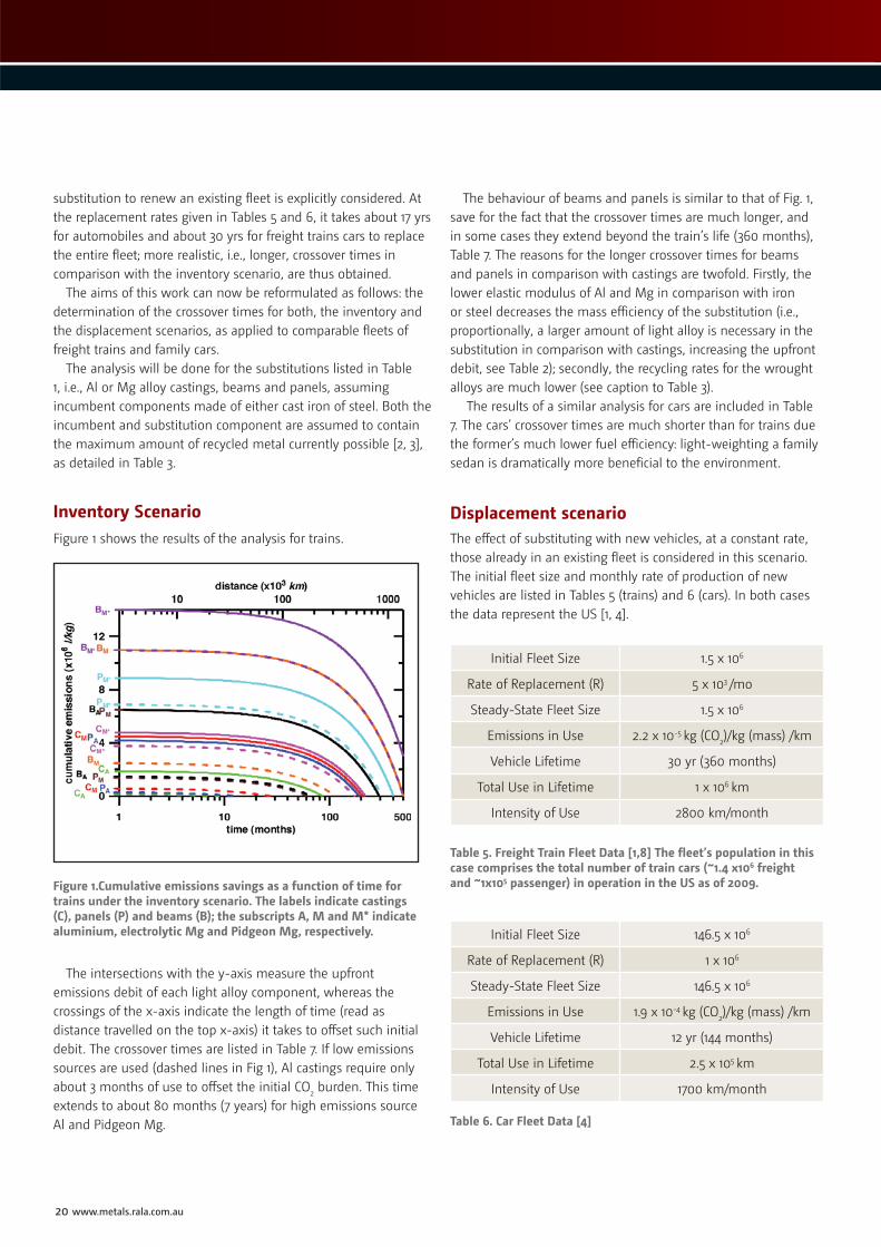
Inventory ScenarioFigure 1 shows the results of the analysis for trains.
Figure 1.Cumulative emissions savings as a function of time for trains under the inventory scenario. The labels indicate castings (C), panels (P) and beams (B); the subscripts A, M and M* indicate aluminium, electrolytic Mg and Pidgeon Mg, respectively.
The intersections with the y-axis measure the upfront emissions debit of each light alloy component, whereas the crossings of the x-axis indicate the length of time (read as distance travelled on the top x-axis) it takes to offset such initial debit. The crossover times are listed in Table 7. If low emissions sources are used (dashed lines in Fig 1), Al castings require only about 3 months of use to offset the initial CO2 burden. This time extends to about 80 months (7 years) for high emissions source Al and Pidgeon Mg.
The behaviour of beams and panels is similar to that of Fig. 1, save for the fact that the crossover times are much longer, and in some cases they extend beyond the train’s life (360 months), Table 7. The reasons for the longer crossover times for beams and panels in comparison with castings are twofold. Firstly, the lower elastic modulus of Al and Mg in comparison with iron or steel decreases the mass efficiency of the substitution (i.e., proportionally, a larger amount of light alloy is necessary in the substitution in comparison with castings, increasing the upfront debit, see Table 2); secondly, the recycling rates for the wrought alloys are much lower (see caption to Table 3).
The results of a similar analysis for cars are included in Table 7. The cars’ crossover times are much shorter than for trains due the former’s much lower fuel efficiency: light-weighting a family sedan is dramatically more beneficial to the environment.
Displacement scenarioThe effect of substituting with new vehicles, at a constant rate, those already in an existing fleet is considered in this scenario. The initial fleet size and monthly rate of production of new vehicles are listed in Tables 5 (trains) and 6 (cars). In both cases the data represent the US [1, 4].
Initial Fleet Size 1.5 x 10⁶
Rate of Replacement (R) 5 x 10³ /mo
Steady-State Fleet Size 1.5 x 10⁶
Emissions in Use 2.2 x 10⁻⁵ kg (CO2)/kg (mass) /km
Vehicle Lifetime 30 yr (360 months)
Total Use in Lifetime 1 x 10⁶ km
Intensity of Use 2800 km/month
Table 5. Freight Train Fleet Data [1,8] The fleet’s population in this case comprises the total number of train cars (~1.4 x10⁶ freight and ~1x10⁵ passenger) in operation in the US as of 2009.
Initial Fleet Size 146.5 x 10⁶
Rate of Replacement (R) 1 x 10⁶
Steady-State Fleet Size 146.5 x 10⁶
Emissions in Use 1.9 x 10⁻⁴ kg (CO2)/kg (mass) /km
Vehicle Lifetime 12 yr (144 months)
Total Use in Lifetime 2.5 x 10⁵ km
Intensity of Use 1700 km/month
Table 6. Car Fleet Data [4]

SuperchargeYour GreenSand SystemGreen sand systems work harder and last longer withTRUBOND®. These sodium bentonite grades mull in quicklyand undergo a controlled hydration to develop a stronger,more elastic adhesive. TRUBOND delivers excellent green compressive and hot strength properties and maintains itsworking bond in repetitive exposure to high heat loads and metal temperatures.
SODIUM BENTONITE
For more information and availability:[email protected]
® TRUBOND is a registered trademark. All rights reserved. ©2011
Figure 2 shows the results of the modelling. The linear
functions represent the cumulative upfront debit created by the manufacturing of new vehicles at a constant rate. The lines labelled Scars and Strains (the upward concave parabolic functions) are the cumulative savings resulting from the driving of the new, more fuel efficient cars. The intersections of the linear functions with the lines S
■ indicate the fleets’ crossover times for each
substitution. Beyond the crossing the cumulative savings more than offset the manufacturing burden of new vehicles incorporated and the emissions of the fleet at a whole decrease.
A crossover time shorter than the life of the vehicles (indicated in Fig. 2 by the vertical dashed lines) means that the substitution is feasible. All other substitutions are labelled non-viable (nv) in Table 7. For several of the more energy intensive substitutions the crossover never happens.
Figure 2 makes evident that the feasibility of any substitution is largely determined by how steep the relevant S curve is. The S curve is steeper for cars as a consequence of their lower fuel efficiency, hence more substitutions are feasible for cars than for trains, see Table 7 for an overview.
The crossover times for both the inventory and displacement scenarios are compared in Table 7. The inventory scenario produces much shorter times than the fleet one, by a factor of between 2 and 3.
Figure 2. Fleet analysis for substitution in cars (left-hand y-axis) and trains (right-hand and top-x-axis).Labels to the substitutions as in Fig. 1. The linear functions represent the upfront debits of the new vehicles for each type of substitution. The upward concave curves Scars and Strains are the cumulative fleet’s savings for both trains and cars. The vertical dashed lines are the life expectancy of cars (144 months) and trains (360 months). For clarity, not all possible substitutions are plotted. See Table 7 for crossover times.
22 www.metals.rala.com.au
This points out to the more realistic nature of the fleet analysis. As for the inventory scenario, the fleet crossover times for trains are much longer than for cars. This, again, is the result of the higher fuel efficiency of trains.
Aluminium alloy castings combined with clean energy sources are the most favourable case for both cars and trains. This is largely the result of the high recycling rates possible with Al alloys. Electrolytic Mg castings follow. In contrast, Pidgeon Mg castings are largely unviable, as are beams and panels.
By and large, the analysis for all three applications (castings, beams and panels) shows that light alloys substitutions are not necessarily viable, especially when a fleet analysis is carried out. The Pidgeon Mg is a point in case as its use appears unjustified in environmental terms save for the most favourable case of castings. The same conclusion applies to Al produced by high CO2 sources, such as those used in Australia.
ConclusionsThe environmental feasibility of light alloys substitutions in freight trains was discussed incorporating exchange constants for the cases of individual vehicles and for an existing fleet of trains, and compared with equivalent data for automobiles. Light alloy (aluminium and magnesium) substitutions for ferrous castings, panels and beams were considered, as well as whether the energy source for the production of primary metals was of either high or low CO2 content.
Castings result in the shortest times to offset upfront emissions debit in all scenarios. Panels are the next most feasible substitution, followed by beams.
The much higher fuel efficiency of trains results in longer crossover times for all scenarios.
A low emissions energy source in combination with a high rate of post-consumers scrap recycling is a condition sine qua non for all substitutions to be feasible when applied to high fuel efficiency transportation such as trains. At present this condition
is most likely to be met by castings of either aluminium or electrolytic magnesium alloys.
Magnesium produced by the Pidgeon method is environmentally unviable in all train applications due to its high embodied energy. Similar conclusions can be made for Al produced using high emissions energy sources. ■
TECHNICAL FEATURE
Inventory Crossover time, Castings (months)
Fleet Crossover time, Castings (months)
Fleet Crossover time, Panels (months)
Fleet Crossover time, Beams (months)
High CO2 Cars Trains Cars Trains Cars Trains Cars Trains
Fe ➝ Al 33 86 70 224 162 nv nv nv
Fe ➝ Mg 77 205 179 nv nv nv nv nv
Fe ➝ Mg* 82 218 196 nv nv nv nv nv
Low CO2
Fe ➝ Al 3 8 10 23 15 31 56 176
Fe ➝ Mg 10 25 23 76 53 166 92 298
Fe ➝ Mg* 64 173 144 nv nv nv nv nv
Table 7. Crossover times for car and train applications under the inventory and displacement (fleet) scenarios; nv indicates crossover times well beyond the vehicle’s life (144 months for cars; 360 months for trains).
References[1] M. Skillinberg and J. Green: Light Met. Age 2007, vol. 65, pp. 8-12.[2] C.H. Caceres: Mater.Design 2009, vol. 30, pp. 2813-2822.doi:10.106/j.
matdes.2009.01.027[3] C.H. Cáceres: Metall. Mater. Trans. 2007, vol. 38A, pp. 1649-1662 doi:1610.1007/s11661-
11007-19156-z [4] F. Field, R. Kirchain, and J. Clark: Journal of Industrial Ecology 2000, vol. 4, pp. 71–91
doi:10.1162/108819800569816 [5] S. Ramakrishnan and P. Koltun, in: A. Luo (Ed.) Magnesium Technology 2004,
Charlotte, USA; TMS (The Minerals, Metals and Materials Society), 2004, pp. 173-178.[6] S. Ramakrishnan and P. Koltun: Resources, Conservation and Recycling 2004, vol.
42, pp. 49-64.[7] M.F. Ashby: Materials selection in mechanical design (Butterworth-Heinemann,
Oxford, 2005).[8] http://www.bts.gov/publications/national _transportation_statistics/html/
table_01_11.html(accessed on April 2011).
Martin Prekel is a Mechanical Engineer, recently graduated with Honours from the University of Queensland, specialising in fluid mechanics and materials. His Honours thesis dealt with light alloy substitutions in trains. He now works as a project engineer designing and overseeing construction of pipelines for coal seam water treatment works.
Carlos H. Cáceres, Ph.D., Reader in Casting Technology, Materials Engineering, the University of Queensland, is a Chief Investigator within the Centre of Excellence for Design in Light Metals and the CRC-CAST. His current research focuses on environmental issues and the mechanical behaviour of magnesium and aluminium alloy castings.


TECHNICAL FEATURE
24 www.metals.rala.com.au
Introductionhermal analysis techniques may be used to predict the degree of grain refinement of hypoeutectic aluminum-silicon alloy based upon an analysis and interpretation
of cooling curve characteristics observed during solidification [1-2]. However, without correct set-up of apparatus, data acquisition and procedure such analysis and interpretation may lead to discrepancies when compared to the actual solidified structures. This implies that other factors also influence the characteristics of the cooling curve hence confusing interpretation. In order to gain a better insight into this problem, the present work has examined how factors such as casting conditions, arrangements of the apparatus and data acquisition, may affect the cooling curve characteristics. Casting trials were designed based on a Taguchi method. From the conditions addressed in the present study, it was found that degassing, pouring temperature, cooling rate, and sampling rate all appear to affect the degree of undercooling observed in a cooling curve.
Initial studyThe alloy used in this present work was a hypoeutectic grade aluminum-silicon alloy, A356, one of the most widely used foundry alloys. Table 1 gives nominal composition the A356 alloy.
Alloy Si Mg Cu Mn Fe Zn Ti Al
A356 6.76 0.20 0.02 0.06 0.56 0.11 0.08 remainder
Table 1. Composition analysis of the A356 alloy used in this study (wt.%).
Each melt of 5 kg of A356 alloy was prepared in an electric resistance furnace and raised to a maximum temperature of 800°C. Prior to tapping the liquid metal was treated with a foundry-grade cleaning flux and the dross was then carefully removed before taking samples at regular intervals. Each test sample was poured into a cylindrical stainless cup equipped with a calibrated thermocouple as shown in schematic form in Figure 1. A cooling curve of each melt sample was plotted from its acquired thermal data. These included degree of undercooling at the beginning of primary aluminum nucleation, eutectic temperature and time. The data for thermal analysis were collected using the “aRite TA System” developed during earlier studies by the research group. In the first experiments no grain refining or other modification treatment was used.
Figure 1. Schematic view of thermal data acquisition.
Towards improving the thermal analysis technique in casting of hypoeutectic aluminum-silicon alloyBy Sompob Phetchcrai, John Pearce, Julathep Kajornchaiyakul.
T
A COOLING CURVE OF EACH MELT SAMPLE WAS PLOTTED FROM ITS ACQUIRED THERMAL DATA.


26 www.metals.rala.com.au
TECHNICAL FEATURE
Because several parameters can have some effect on cooling curve characteristics, it was considered necessary to use a design of experiment (DOE) approach based on a balanced Taguchi orthogonal array [3]. The Orthogonal array L8 (2
7) was selected as most suitable since five main factors and two interactions at two levels could be entered in this array as shown in Table 2. The output is identified as the degree of undercooling temperature with the aim of achieving high undercooling values for the primary arrest. Signal-to-noise ratios [3], according to Taguchi, were calculated for the case in which “larger is better” for the output as given in equation 1:
Larger the better: S/N = -10log [1/n ∑ (1/yi ) 2] (1)
n = number of experiment yi = Output
Factor Level 1 Level 2
A Degassing NO YES
B Pouring Temperature (°C) 700 800
C Cooling Rate Stainless cup Stainless cup preheated
D Position of Measurement Center Wall
E Data sampling rate 2 data/sec. 10 data/sec.
Interaction factors: BxC, CxD
Table 2. Values of the parameters and interactions
Experimentnumber
Factor Degree ofUndercooling (oC)C B B x C D C x D A E
1 1 1 1 1 1 1 1 0.72
2 1 1 1 2 2 2 2 0.83
3 1 2 2 1 1 2 2 2.92
4 1 2 2 2 2 1 1 1.48
5 2 1 2 1 2 1 2 2.08
6 2 1 2 2 1 2 1 1.47
7 2 2 1 1 2 2 1 2.51
8 2 2 1 2 1 1 2 1.84
Level C B B x C D C x D A E
1 1.489 1.278 1.476 2.059 1.738 1.531 1.545
2 1.976 2.188 1.989 1.406 1.727 1.934 1.920
Difference 0.487 0.910 0.512 0.652 0.010 0.402 0.375
Rank 4 1 3 2 7 5 6
Level C B B x C D C x D A E
1 2.073 1.327 2.218 5.207 3.774 3.058 2.973
2 5.755 6.501 5.610 2.620 4.054 4.770 4.855
Difference 3.681 5.173 3.393 2.587 0.279 1.713 1.882
Rank 2 1 3 4 7 6 5
Table 3. Orthogonal array (L8 27) with undercooling results.
Table 4. Main effect and signal-to-noise ratio analysis.
(b) Signal to noise ratios at each level with differences.
(a) Main Effect: Mean values listed at level 1 and level 2 for each factor with differences.

Results and analysis of initial studyTable 3 shows the degrees of undercooling recorded during the experiments based on the L8 2
7 Orthogonal array. From these values the main effects and signal-to-noise ratios were calculated as listed in Table 4.
To compare their effect on measured undercooling (as indicated by the differences between means at each level) each of the factors has been ranked 1 to 7. Pouring temperature (B) had the largest effect, on both measured undercooling and on signal to noise ratio. There was no interaction between factors C and D but there was important interaction between B and C. Overall it was concluded that to provide the highest measured value of primary arrest undercooling and best signal to noise ratio the following conditions should be used:
A2 Degassing
B2 Pouring temperature at 800oC
C2 Stainless steel sample cup to be pre-heated
D1 Position thermocouple at centre
E2 Sampling data rate at 10 data per second
Although the effect was slight (ranked 5 on main effect & 6 on signal to noise) the observation that degassing gave a higher level of undercooling was unexpected since other work at MTEC on A356 into the evaluation of hydrogen in liquid aluminium by means of thermal analysis has clearly shown that the degree of undercooling for nucleation of the primary aluminium phase becomes smaller as the amount of dissolved hydrogen is reduced [4], showing similar trends to other work on the effect of hydrogen in A319 alloy [5]. It was decided that degassing would be used as a factor in the controlled conditions used in the trial below since it would then remove any variation in undercooling caused by any variation in dissolved hydrogen level.
Follow up trial on use of thermal analysis to monitor grain sizeFurther experimental work continued to examine the reliability of thermal analysis in monitoring grain refinement by comparing pouring samples under controlled and non-controlled conditions. The latter includes variation in pouring temperature, thermocouple position, level of gas, and sample cup temperature. The controlled conditions selected were as listed above following the findings of the DOE work. Cooling curves were recorded for grain refined melts of
Foundry Investment Diecasting
Offices:
[email protected]+61 (0) 845 370 3232
ERP Cast Metal Specific
Booth #12G04
June 28th - J
uly 2nd
28 www.metals.rala.com.au
TECHNICAL FEATURE
A356 with Al–5%Ti–1%B master alloy rod used for refinement to achieve Ti and B levels of 2 wt% for holding time about 20 min before pouring samples. Metallographic specimens were taken on horizontal sections 10 mm. above the bottom surface of each thermal analysis sample. After etching with HF to reveal the grain structure, grain size analysis was carried out using the linear intercept method.
Table 5 shows the values recorded for undercooling and grain size measurements for a number of tests under un-controlled and controlled conditions. The cooling curve data for the un-controlled conditions shows no correlation between the undercooling and measured grain size whereas for the controlled conditions, apart from the value of 1.67o, the undercooling recorded is consistent with measured grain size.
SummaryThe present study is being continued to gain a better insight into both the melt and test factors that influence the characteristic features of cooling curves towards improved reliability and accuracy of the thermal analysis technique for monitoring of grain refinement during casting of the hypoeutectic aluminum-silicon alloy.
The work shows that foundries need to take great care when using thermal analysis measurements based on degree of undercooling of primary nucleation to indicate grain size or misleading results will be obtained. Factors that must be controlled for reliable measurement include the level of dissolved hydrogen, pouring temperature, and cooling rate. ■
Table 5. Undercooling (oC) and grain size (micron) measurements for repeat tests under un-controlled and controlled thermal analysis test conditions.
Un-controlled Conditions Controlled ConditionsUndercooling Grain Size Undercooling Grain Size
0.89 2485 1.67 2440
1.15 2628 2.41 2485
1.65 2672 2.60 2485
1.97 2628 2.63 2576
2.02 2586 2.77 2586
2.63 2576 2.78 2576
References[1] F. Bekaert & E. Wettinck: “Study of
the grain refinement of A356 and its control by thermal analysis”, Aluminium (Germany) Vol. 72 (1996) pp. 442-447.
[2] S.A.Levy: “Monitoring grain refiner performance using thermal analysis”, Light Metal (1990) pp.831-836.
[3] P.J. Ross: “Taguchi Techniques for Quality Engineering”, 2nd edition (1996) McGraw-Hill, New York, US.
[4] S. Phetchcrai, S. Luankosolchai, W. Samit and J. Kajornchaiyakul: “Evaluation of hydrogen in liquid aluminium by means of thermal analysis”, Proceedings of METAL 2010 – 19th Int. Conf. on Metallurgy & Materials, ASMET, 18-20th May 2010, Roznov pod Radhostem, Czech Republicpp.664-668.
[5] A. Mitrasinovic, F.C. Robles Hernandez, M. Djurdjevic and J.H. Sokolowski: “On-line prediction of the melt hydrogen and casting porosity level in 319 aluminium alloy using thermal analysis”, Mat. Science & Engineering A, Vol.428 (2006) pp.41-46.
Co-AuthorsDr Julathep Kajornchaiyakul graduated in 1992 with a B.Eng. in Metallurgical Engineering from Chulalongkorn University, Bangkok, Thailand. He then undertook post-graduate studies in the US obtaining his M.Sc. in “Mechanical Metallurgy: Deformation Processing of Metals” from the Colorado School of Mines, Golden in 1996, and his Ph.D. in “Brittle Materials Manufacturing: Abrasive Machining & Processing” at University of Connecticut in Storrs CT in June 2000. Since September 2000 he has been working as a R&D Engineer at MTEC – the National Metal and Materials Technology Center under the National Science and Technology Development Agency (NSTDA) of Thailand. He is now a Senior Researcher in the Design & Engineering Research Unit at MTEC working mainly on Foundry Engineering and Aluminium Processing. He is the current Chairperson of the Aluminium Technology Forum of Thailand and a Vice President of the Thai Foundry Association (former Thai Foundrymen’s Society). He is also a member of the Technical Committee of the Federation of Thai Industry’s Clustering Development Board relating to Machinery and Metallurgical Industries.
Somphob Phetchcrai graduated in 1999 with a B.Eng. in Tool and Materials Engineering from King Mongkut’s University of Technology in Thonburi. Since 2000 he has been working as a research engineer in the Foundry Engineering R & D section at MTEC, the National Metals and Materials Technology Centre, Pathumthani, Thailand. While working he continued with his post-graduate studies on a part time basis and in 2009 was awarded his M.Eng. from the Leadership in Manufacturing Competitiveness Programme at King Mongkut’s.
THE PRESENT STUDY IS BEING CONTINUED TO GAIN A BETTER INSIGHT INTO BOTH THE MELT AND TEST FACTORS...
Unit 5/23 Kenworth Place, Brendale Qld 4500 Australia
Phone: +61 7 3881 3262Fax: +61 7 3881 3265
Web: www.coolfog.com.auEmail: [email protected]
Coolfog™ ...The New Safe Alternative to Temperature Reduction, Dust Suppression and
Odour Elimination in Foundry Facilities
30 www.metals.rala.com.au
TECHNICAL FEATURE
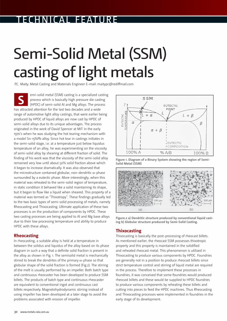
emi-solid metal (SSM) casting is a specialized casting process which is basically high pressure die casting (HPDC) of semi-solid Al and Mg alloys. The process
has attracted attention for the last two decades and a wide range of automotive light alloy castings, that were earlier being produced by HPDC of liquid alloys are now cast by HPDC of semi-solid alloys due to its unique advantages. The process originated in the work of David Spencer at MIT in the early 1970’s when he was studying the hot tearing mechanism with a model Sn-15%Pb alloy. Since hot tear in castings initiates in the semi-solid stage, i.e. at a temperature just below liquidus temperature of an alloy, he was experimenting on the viscosity of semi-solid alloy by shearing at different fraction of solid. The finding of his work was that the viscosity of the semi-solid alloy remained very low until about 50% solid fraction above which it began to increase dramatically. It was also observed that the microstructure contained globular, non-dendritic α-phase surrounded by a eutectic phase. More interestingly, when this material was reheated to the semi-solid region of temperature, in static condition it behaved like a solid maintaining its shape, but it began to flow like a liquid when sheared. This property of a material was termed as “Thixotropy”. These findings gradually led to the two basic types of semi-solid processing of metals, namely Rheocasting and Thixocasting. Ultimate application of these two processes is on the production of components by HPDC. These two casting processes are being applied to Al and Mg base alloys due to their low processing temperature and ability to produce HPDC with these alloys.
RheocastingIn rheocasting, a suitable alloy is held at a temperature in between the solidus and liquidus of the alloy based on its phase diagram in such a way that a definite solid fraction is present in the alloy as shown in Fig. 1. The semisolid metal is mechanically stirred to break the dendrites of the primary α-phase so that globular shape of the solid fraction is formed (Fig.2). The stirring of the melt is usually performed by an impeller. Both batch type and continuous rheocaster has been developed to produce SSM billets. The products of batch type and continuous rheocaster are equivalent to conventional ingot and continuous cast billets respectively. Magnetohydrodynamic stirring instead of using impeller has been developed at a later stage to avoid the problems associated with erosion of impeller.
Figure 1. Diagram of a Binary System showing the region of Semi-Solid Metal (SSM)
Figure.2 a) Dendritic structure produced by conventional liquid cast-ing b) Globular structure produced by Semi-Solid Casting.
ThixocastingThixocasting is basically the post-processing of rheocast billets. As mentioned earlier, the rheocast SSM possesses thixotropic property and this property is maintained in the solidified and reheated rheocast metal. This phenomenon is utilized in Thixocasting to produce various components by HPDC. Foundries are generally not in a position to produce rheocast billets since strict temperature control and stirring of liquid metal are required in the process. Therefore to implement these processes in foundries, it was conceived that some foundries would produced rheocast billets and these would be supplied to HPDC foundries to produce various components by reheating these billets and cutting into pieces to feed the HPDC machines. Thus Rheocasting and Thixocasting processes were implemented in foundries in the early stage of its development.
Semi-Solid Metal (SSM) casting of light metalsP.C. Maity. Metal Casting and Materials Engineer E-mail: [email protected]
S

METAL Casting Technologies June 2011 31
Recently developed SSM casting processesVarious stirring methods including “egg beater” type arrangement, single or twin helical screws, and rolling method have been attempted to produce semi-solid metal in the initial phase of their development. Although these processes achieved their desired goals, the processes have been commercially unfeasible in one way or another. Mechanical stirrers erode in the harsh environment of liquid metal and need to be replaced frequently. Furthermore, gas from the atmosphere and oxide layers formed are mixed with the slurry, affecting mechanical properties of the castings. In case of magnetohydrodynamic stirring, the cost of equipment is very high. Therefore alternative methods of producing semi-solid slurry with globular structure have been attempted in the last decade based on three different mechanisms leading to fine globular / equiaxed microstructures. First, fine equiaxed microstructure was developed in superalloys by pouring low superheat liquid metal in a chill mold. Second, very fine grain structure could be formed by spraying liquid metal over a substrate. Lastly, highly grain refined copper alloys could be produced by Properzi Process by pouring liquid metal with low superheat. The cast billet produced by the above three methods could be heated to the semisolid state to form a billet with globular structure, exhibiting thixotropic behaviour. Therefore the recently developed methods of SSM casting are based on a concept that a semi-solid slurry can be obtained via copious nucleation, inhibition of growth and remelting and redistribution of the nuclei throughout the melt by suitable means. The objective in most of these processes are also aimed at producing the semi-solid slurry close to the die casting machine in a economic way so that reheating of billet for thixocasting are not required. A few of these new semi-solid metal processes are discussed below.
Strain-Induced Melt Activation (SIMA) ProcessDeveloped by Kirkwood, this process is based on the mechanism of dendrite fragmentation in the solid state of an alloy and then reheating to the semisolid regime. The high angle grain boundaries in the structure are melted preferentially, and a globular microstructure develops by recrystallization and coarsening of the new grains.
New Rheo-Casting (NRC)This process was developed at the early stage of development of SSM casting by UBE Industries, Japan. In this process, low superheat liquid metal is poured onto the cool sidewall of a tilted crucible type receiver at the end of a piston of die casting. Nucleation takes place on the cool sidewalls and the nuclei are redistributed in the melt due to forced convection. Once the required volume of liquid metal is poured, the crucible and piston are straightened into a vertical HPDC machine. The machine thermally manages the required solid fraction and then the slurry is cast.
Direct thermal methodThis method was developed by University College Dublin, where the liquid metal is poured into a thin walled copper / steel mold. The thickness of the mold is decided based on the thermal properties of the liquid metal and the mold and the volume of liquid metal poured into the mold, so that after heat transferred to the mold at equilibrium, the liquid metal transforms to semi-solid metal with globular structure. It is believed that under slow rate of external cooling of liquid metal in a thin mold, ripening of the primary solid occurs during this pseudo-isothermal hold period and globular primary phase forms. After this hold period the mold is quenched in water to restore the desired structure.
Cup methodIn this method, developed by Japan and Thailand researchers, the liquid metal is poured into a metallic cup like pouring hot water in a cup. After completion of heat transfer between the liquid metal and the cup, an equilibrium is reached and semi-solid alloy is formed in the cup which is subsequently transferred into a die casting / squeeze casting machine.
Beckwith Macbro Resin Coated Sands
Contact : Rob Dalla Via
30 Devon Road Devon Meadows, Melbourne
Telephone: +61 3 5995 4244
Mobile: 0417 332 723 Fax: +61 3 5995 5030
E-mail: [email protected]
Website: www.beckwithmacbro.com.au
All grades of resin coated sand used for shell molding and shell cores for ferrous and non-ferrous applications
PRODUCTS■ Range of resin strengths from 1.0% to 5.0%■ Silica, Zircon, Chromite coated sands
or blended mixes■ Coated Sands of diff erent AFS
typically from 50-90 AFS■ Thermal Reclaimed Coated Sands
SERVICES■ Full technical and trouble shooting service.■ On-site shell core and shell
molding facility to evaluate the product applications.
■ Laboratory facility to ensure product quality.
nds FOR SALE
SHELL CORE MACHINESSHELL MOULD MACHINES
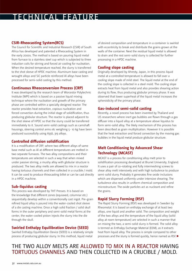
32 www.metals.rala.com.au
TECHNICAL FEATURE
THE TWO ALLOY MELTS ARE ALLOWED TO MIX IN A REACTOR HAVING TORTUOUS CHANNELS AND THEN COLLECTED IN A CRUCIBLE / MOLD.
CSIR-Rheocasting System(RCS)The Council for Scientific and Industrial Research (CSIR) of South Africa has developed and patented a Rheocasting System in the early 2000s. The method is based on pouring liquid metal from furnace to a stainless steel cup which is subjected to three induction coils for stirring and forced air cooling for nucleation. When the desired temperature reached, the slurry is transferred to the shot sleeve of HPDC machine. Aluminum base casting and wrought alloys and SiC particle reinforced Al alloys have been processed for semi-solid casting by this method.
Continuous Rheoconversion Process (CRP) It was developed by the research team of Worcestor Polytechnic Institute (WPI) which is based on a passive liquid mixing technique where the nucleation and growth of the primary phase are controlled within a specially designed reactor. The reactor provides heat extraction, copious nucleation and forced convection during the initial stage of solidification, thus producing globular structure. The reactor is placed adjacent to the shot sleeve of HPDC so that the slurry could be transferred immediately to it. Sound semi-solid castings such as camshaft housings, steering control arms etc weighing 5- 10 kg have been produced successfully using A356, 319 alloys.
Controlled diffusion solidificationIt is a modification of CRP, where two different alloys of same base metal such as Al at different temperatures are melted in two separate furnaces. The two alloy compositions and their temperatures are selected in such a way that when mixed under passive stirring, a mushy alloy with globular structure is produced. The two alloy melts are allowed to mix in a reactor having tortuous channels and then collected in a crucible / mold. It can be used to produce thixocasting billet or can be cast directly in a HPDC machine.
Sub-liquidus castingThis process was developed by THT Presses. It is based on the knowledge that different zones (equiaxed, columnar etc.) sequentially develop within a conventionally cast ingot. Pre-grain refined liquid alloy is poured into the water-cooled shot sleeve of a die casting machine. Once a high solid fraction / solid skull forms in the outer periphery and semi-solid metal forms at the center, the water-cooled piston injects the slurry into the die through the skull.
Swirled Enthalpy Equilibration Device (SEED)Swirled Enthalpy Equilibration Device (SEED) is a relatively simple process of producing globular slurry. In this method, liquid metal
of desired composition and temperature in a container is swirled with eccentricity to break and distribute the grains grown at the walls of the container. Next the residual liquid metal is allowed to drain and the rest semi-solid slurry is collected for further processing in a HPDC machine.
Cooling slope castingOriginally developed by Ahresty, Japan, in this process liquid metal at a controlled temperature is allowed to fall over a cooling slope made of mild steel. The liquid metal at the end of the cooling slope is collected in a steel mold. The cooling slope extracts heat from liquid metal and also provides shearing action during its flow, thus producing globular primary phase. It was observed that lower superheat of the liquid metal increases the spheroidicity of the primary phase.
Gas-induced semi-solid castingRecently, a novel process has been invented by Thailand and US researchers where inert gas bubbles are flown through a gas diffuser into a liquid alloy at a temperature above liquidus to form semi-solid alloy. The likely mechanism of this process has been described as grain multiplication. However it is possible that the heat extraction and forced convection by the moving gas bubbles in the liquid metal produce globular structure.
Melt Conditioning by Advanced Shear Technology (MCAST)MCAST is a process for conditioning alloy melt prior to solidification processing developed at Brunel University, England. It uses a pair of co-rotating and fully intermeshing screws to shear alloy melt intensively and with high turbulence to produce semi-solid slurry. Probably it generates fine oxide inclusions which are dispersed uniformly under intensive shearing. The turbulence also results in uniform chemical composition and microstructure. The oxide particles act as nucleant and refine the grains.
Rapid Slurry Forming (RSF)The Rapid Slurry Forming (RSF) was developed in Sweden by Rheometal. It is based on enthalpy exchange of at least two alloys, one liquid and another solid. The composition and weight of the two alloys and the temperature of the liquid alloy (solid alloy at room temperature) are selected in such a manner that on mixing the two, a semi-solid slurry is formed. The solid alloy is termed as Enthalpy Exchange Material (EEM), as it extracts heat from liquid alloy. The process is simple compared to other processes and the slurry is formed quickly, hence named as RSF.


34 www.metals.rala.com.au
Hong-Nano Cast Method (H-NCM)An advanced rheocasting process has been developed at Yonsei University, South Korea named as Hong-Nano Cast Method (H-NCM). In this method, the semi-solid slurry is produced by nucleation in which the nuclei of the primary α-phase formed in the melt are prevented to grow into dendrites. Instead they are grown into fine globular particles in presence of numerous nuclei. Recently commercial rheo-diecasting machines based on this method has been developed and being used to produce Al alloy automotive components.
ThixomoldingThis method is quite different from other semi-solid casting processes. It uses a modified plastic injection molding machine to produce Mg alloy components. Mg alloy pieces are fed into heated barrel and screw of the machine, which also provides shearing forces, injects the metal into the die when it is semi-solid. Argon atmosphere is provided in the barrel to inhibit oxidation of Mg alloy. Various electronic, automotive and other components are being produced by this process. Currently thixomolding of Al alloys are under development.
Several other semi-solid casting processes have been developed such as Advanced Semi-solid Casting Technology by Honda Japan, Advanced Thixotropic Metallurgy by CSIRO Australia, Rheo-diecasting by Korea Institute of Industrial Technology etc. have been developed and commercialized for the production of semi-solid cast Al alloy components.
Advantages of SSM Casting Processes● SSM components without gas porosity defect
In conventional HPDC, liquid metal is injected into the die at a high speed and high pressure to fill the die cavity completely and to consolidate the casting. During high speed injection, liquid metal splashes and entraps air / gas and oxide layer over liquid metal. However in SSM, the splashing is avoided due to its mushy state. Hence porosity defects in castings are minimised. Hence blister type of defect which appears on heat treatment of die castings is also eliminated.
● Lower shrinkage of castingsSince the SSM temperature is lower than Liquid metal temperature of a particular alloy, the shrinkage is less. Hence shrinkage related defects are minimized.
● Improved Die lifeDie life is a function of liquid metal temperature. More the die erosion is, higher the metal temperature. Since the SSM temperature is lower than its liquid counterpart, the die life improves. In addition to die surface erosion, thermal fatigue effect on die is reduced at lower SSM temperature, which also contributes to improved die life.
● Excellent mechanical propertiesThe mechanical properties of SSM castings are better than
liquid metal based castings due to globular microstructure and reduced porosity.
● Uniform microstructureThe microstructure of SSM castings is more uniform due to less
temperature gradient at mold-metal interface upon filling of die cavity.
Disadvantages of SSM casting processes● Extra processing cost of semi-solid metals
Generally an additional attachment / device is to be set up adjacent to an existing HPDC bearing extra cost.
● Strict temperature ControlIn most of the processes, a strict temperature control in the regime of solidus-liquidus or near liquidus is necessary to achieve globular slurry.
● Inability to produce Complex and thin parts Since the semi-solid metal has less fluidity compared to fully liquid metal, the filling of thin sections would be difficult.
ConclusionA number of methods for processing semi-solid metals based on Al and Mg have been developed in the last two decades and some of them are being used commercially to produce automotive and other light metal castings. Although several options are available to light metal HPDC industries to produce SSM castings, selection of the right process needs to be decided on the basis of their cost-effectiveness in terms of quality requirements for a specific alloy and component to be produced. ■
References1. D. P. Spencer, R. Mehrabian and M. C. Flemings, Metallurgical Transactions, 3
(1972) p.1925.2. R. D. Doherty, H. –I. Lee and E. A. Feast, Materials Science and Engg. 65 (1984)
p.181.3. Metals Handbook, Vol.15, 9th Ed. ASM International, OH., p.767.4. M. C. Flemings, Metallurgical Transactions A, 22A (1991) p.957.5. D. H. Kirkwood, Int. Materials Reviews, 39(5) (1994) p.173.6. UBE Industries Ltd. European Patent No. EP 0 745694 A1 (1996) p.117.7. De Figueredo A, Science and Technology of Semi-solid Metal Processing,
NADCA, USA (2001).8. F. Czerwinski, A. Zielinska-Lipiec, P. J. Pinet and J. Overbeeke, Acta Materialia, 49
(2001) p.1225.9. D. J. Browne et al. Int. J. Cast Metals Research, 16(4) (2003) p.418.10. J. L. Jorstad, Proc. 8th Int. Conf. On Semi-Solid Alloys and Composites (2004)
Limassol, Cyprus.11. Q. Y. Pan, M. Findon and D. Apelian, Proc. 8th Int. Conf. On Semi-Solid Alloys
and Composites (2004) Limassol, Cyprus.12. R. A. Martinez, PhD Thesis, MIT, Cambridge USA (2004).13. D. Doutre, J. Langlais and S. Roy, Proc. 8th Int. Conf. On Semi-Solid Alloys and
Composites (2004) Limassol, Cyprus.14. S. Sh ankar et.al. Proc. 8th Int. Conf. On Semi-Solid Alloys and Composites
(2004) Limassol, Cyprus.15. D. Apelian, Q. Y. Pan and M. Findon, Die Casting Engineer, 48(1) (2004) p.22.16. D. J. Browne, M. J. Hussey and A. J. Carr, Proc. 8th Int. Conf. On Semi-Solid
Alloys and Composites (2004) Limassol, Cyprus.17. H. Cao and M. WessÐn, International Patent No. PCT/SE2005/001889.18. E. C. Legoretta, H.V. Atkinson and H. Jones, Proc. 5th Int. Conf. On Solidification
Processing, 23-25 July, Sheffield, UK.
TECHNICAL FEATURE

MMOLTEN METAL
Ajax TOCCO Magnethermic®
Corporation
1745 Overland Ave
Warren, OH U.S.A. 44483
Tel: 800-547-1527
Tel: +1-330-372-8511
Fax: +1-330-372-8608
www.ajaxtocco.com
Headquarters For:
THE GLOBAL FORCE IN
INDUCTION TECHNOLOGY
Coreless InductionFurnaces
Channel InductionFurnaces
Melting
Holding
Duplexing
Ferrous
Non-Ferrous
High Power JetFlow Inductors
IND
UC
TIO
N M
ELT
ING

36 www.metals.rala.com.au
TECHNICAL FEATURE
Summaryn-going development work on a new and environmentally sustainable foundry sand binder is discussed. The binder system, called ESbond, is based
on natural, renewable and readily available materials which also produces a benign odour during processing and casting. ESbond could be used in a niche market for shell cores which can be made on existing equipment with minimal modification.
A basic laboratory evaluation of four commercial binder systems (three organic self-set systems and the heat-cured shell binder) and several ESbond binder formulations was conducted. The properties include typical tensile and shear strengths from test specimens and preliminary gas emission results from pyrolysis analysis. The results of a casting trial using ESbond cores on cast iron will also be discussed. The current data suggests that with further development, ESbond can offer a viable alternative to current technologies with satisfactory strength, low cost, ease of shake-out and less harmful emission to the environment.
1. IntroductionThere is growing interest in the foundry industry for more environmentally friendly sand binder systems than the traditional ones. This paper reports on a basic study of the CSIRO ESbond sand binder which represents a potentially more environmentally sustainable technology.
Current organic binder systems are petro-chemical based and emit potentially harmful gases to the atmosphere during the core/mould manufacturing process and more particularly during the casting process (1, 2, 3). The organic chemicals (mainly phenol and/or formaldehyde resins) will decompose and give rise to levels
of volatile organic compounds (VOCs), significant levels of oxides of carbon as well as unpleasant odours. The emission of these compounds is subject to more stringent environmental control, and is a concern for foundries. Capturing or destroying gases, smoke and objectionable odours are temporary and expensive solutions. Thus new binders are needed that can eliminate the source of offensive odours and toxic gases, but with equal or better mechanical performance. ESbond was developed in response to the above needs.
ESbond is not a self-set binder, but a heat-cured one that is intended to work similarly to a shell sand binder (also called the shell or Croning process) (4). In the shell process, pre-coated sand is invested and cured in a corebox in a shell core- or mould-making machine. The cores or moulds made with this method are generally hollow with an external shell of a few millimetres thick and good surface finish. However, shell binders use a phenol formaldehyde resin whereas newly developed ESbond is based on naturally derived and less hazardous raw materials. ESbond may thus offer an environmentally sustainable alternative to the shell sand binder without any changes to the equipment or process steps used.
A small-scale laboratory evaluation of several commercial binder systems and ESbond was conducted to compare some indicative property and performance benchmarks. The main aims are to assess the mechanical strength, characterise emitted gases under casting temperature conditions from the selected binder systems and assess the casting performance of the ESbond binders against the shell sand process. Although there are many other attributes that determine the performance of a foundry sand system, this study was limited to strength, volatile emissions and casting characteristics.
Development of an environmentally sustainablefoundry sand binderThang NGUYEN*,**, John CARRIG*,**, Danny MORAN*,**, Xiaoqing ZHANG*** and Sarah KHOR****CAST Cooperative Research Centre, **CSIRO Process Science and Engineering, Melbourne, Australia [email protected], [email protected], [email protected] ***CSIRO Materials Science and Engineering, Melbourne, Australia [email protected], [email protected]
O
THE EMISSION OF THESE COMPOUNDS IS SUBJECT TO MORE STRINGENT ENVIRONMENTAL CONTROL, AND IS A CONCERN FOR FOUNDRIES.

METAL Casting Technologies June 2011 37
2. Laboratory evaluation 2.1 ScopeThe commercial binder systems used in this study are shown in Table 1.
Of the self-set category, the first three binders shown in Table 1 were used to make solid cores at room temperature.
Of the heat-cured category, the commercial shell process and ESbond binders were used. The shell process produces hollow cores cured at temperatures between 250-300°C on a shell core machine (SCM). This is the standard equipment for the shell sand process. The ESbond binder was prepared for coating the sand using patented formulations, and the coated sand was used to make hollow cores on a SCM, under similar conditions to shell sand.
Five ESbond formulations were originally proposed, but in the work to date, one was found to be unsuitable and only four are included in this study. These formulations are identified simply as F2, F3, F4 and F5.
2.2 Tensile testingAs there are many factors which affect the foundry sand strength, any strength data obtained will be specific to the sand grain properties as well as the actual moulding conditions used and should be regarded as indicative only. All dogbone tensile samples based on AFS standards (5) were made using AFS Grain Fineness Number (GFN) 70 silica sand. They were tested approximately 24 hours after manufacture on a bench-type Hounsfield tensometer fitted with purpose-made jaws for a range of dogbone thicknesses.
Self-set organic bindersDogbone tensile samples were made at room temperature for the 3 self-set binder systems. The solid dogbone samples all had a neck width of 25.4 mm but with 3
thicknesses: 25.4 mm, 16 mm and 8 mm respectively. The tensile results in Table 2 indicate a fair degree of
variability between the samples and appear to be dependent also on atmospheric conditions. High air humidity was observed to increase the strip time during core making and decrease the core strength. There were only minor differences between the strength results across 3 sample thicknesses, with the 8 mm samples showing the highest strengths.
As there was no equivalent data available from the binder manufacturers, it was difficult to compare the above tensile results with published data. The tests indicated that dogbone samples from Poliset binder gave the highest tensile strength followed by Furane (Furotec) and Fenotec.
Heat-cured shell and ESbond bindersDogbone samples using coated sand from the shell process and ESbond binders were made on a hot plate and a shell core machine. Only the 8 mm thick size was used for tensile strength testing. In this thickness, the sample cross section could be made solid whereas the thicker ones may be hollow thus causing uncertainty due to a variable cross sectional area.
For shell binder, various contents ranging from about 1.5% to 5% are used in industry. For iron casting, a higher percentage of binder is used. In this investigation, commercial coated sand at 3.5% content was used. For ESbond binders, various contents between 8-10% were used depending on the formulations (F2 to F5). Table 3 presents the tensile results obtained for dogbone samples made on a hot plate at about 190°C.
Samples for both shell and ESbond sands were also made on the shell core machine (SCM). The corebox was designed to operate at temperatures up to 300°C. Figs. 1 (a) and 1(b) show the dogbone samples from the SCM.
No. Binder Type Description
1 Fenotec 810* Organic no-bake Self-set, phenol formaldehyde urea no-bake binder and an ester hardener
2 Poliset* Organic cold-box Self-set phenol formaldehyde plus isocyanate two-part resin and a catalyst
3 Furotec 101* Furan binder Self-set furan resin with acid catalyst
4 Shell** Shell or Croning Phenol formaldehyde (Novalac) resin with hexamine as catalyst and other additives
*Foseco commercial products **Coated shell sand from Beckwith Macbro Sands (BMS)
Binder Poliset Fenotec Furane
Content (wt. %) 2% resin and 0.1% catalyst 3% resin and 0.6% catalyst 1.5% resin and 0.6% catalyst
No. of samples tested 20 of each size 18 of each size 6 of each size
Average tensile strength ± standard deviation, from all samples (kPa)
1,222 ± 279 354 ± 117 648 ± 88
Table 1. List of commercial binders used in study
Table 2. Tensile strength testing for 3 self-set binders

38 www.metals.rala.com.au
TECHNICAL FEATURE
There was a strong contrast in the odour experienced between shell and ESbond binders. During curing and in casting trials, the shell sand emits quite a pungent and persistent odour, whereas that from ESbond curing was considered not to be offensive, similar to mildly burnt biscuits or toast.
The tensile results for the samples made on the SCM are given in Table 4 and between 7-12 samples were used for each binder condition. ESbond F5 was found to be inconsistent in the sand coating process at the time and as a result not included. The other available ESbond samples, however, did show good hardness and surface definition.
As can be seen in Tables 3 and 4, ESbond samples showed much lower strength than shell sands as well as larger variability in the results. However, the ESbond tensile strengths (Table 4) were higher than two of the self-set binders given in Table 2.
It should be recognised that tensile strength is only one of a suite of properties that foundries will need in their sand cores and moulds. They may not always require the highest strength but an appropriate level without compromising other properties such as permeability. Further development and optimisation will be required for ESbond to improve the tensile strength binders.
2.3 Shear testingShear testing was conducted using a universal sand testing machine. In this test, rectangular bars of sand were made in an electrically heated corebox and tested for flexural strength in a 3-point bending test. The test bars measured 85mm x 30mm x 10mm thick and the corebox temperature was about 250°C for both halves. Figs. 2(a) and (b) show the shear test bar corebox and the test samples. The test bars were left to cool for about an hour before testing.
A B
Fig. 1. 8mm thick dogbone samples of shell sand binders (a) and ESbond binders (b).
Samples Average tensile strength ± standard deviation (kPa)
Shell binder samples (3.5 wt. %) 1839 ± 133
F2 samples at 8% 745 ± 78
F3 samples at 10% 886 ± 116
F4 samples at 8% 925 ± 152
Samples Average tensile strength ± standard deviation (kPa)
Samples Shell binder samples (3.5 wt. % )
2065 ± 204
F2 samples at 8% 1384 ± 195
F2 samples at 10% 1328 ± 279
F3 samples at 10% 1072 ± 142
F4 samples at 8% 1135 ± 283
F4 samples at 10% 1038 ± 225
F5 samples at 10% 1130 ± 238
Table 3. Tensile strength results of hot plate samples from shell and ESbond binders
Table 4. Tensile strength results of SCM samples from shell and ESbond binders
Table 5: Shear test results for ESbond binders
Samples Average tensile strength ± standard deviation (kPa)
F2 at 8% 2415 ± 148
F2 at 10% 2085 ± 94
F3 at 10% 1558 ± 77
F4 at 8% 2229 ± 111
F4 at 10% 2034 ± 128
F5 at 10% 2263 ± 115
F5 samples at 10% 1130 ± 238

METAL Casting Technologies March 2011 39METAL Casting Technologies June 2011 39
Six samples per binder-content combination were tested and the results obtained are given in Table 5. The shell binder shear strength for typical use at an aluminium foundry has been quoted as 2263-2649 kPa. It can thus be seen that ESbond shear strengths compare favourably with these values for shell binder.
2.4 Laboratory gas emission analysis Gas emission characteristics of the various sand binder formulations can be obtained by using standard laboratory analytical techniques. Two such techniques are Pyrolysis-Gas Chromatography-Mass Spectrometry (Py-GC-MS) and Thermo-gravimetric Analysis-Fourier Transform Infrared Spectroscopy (TGA-FTIR).
2.4.1 Pyrolysis- GC- MS analysisThis analysis can identify the chemical nature of the components in the gas emission and their distribution but does not determine the actual volume emitted from a given binder mass.
The binders tested were shell, Furane, Poliset and 3 ESbond formulas F2, F3 and F4. The pyrolysis was carried out separately at 700°C which is applicable to non-ferrous casting (e.g. aluminium and magnesium) and at 1300°C for iron casting. The probe containing the sample (1.5 mg for 700°C and 4.5 mg for 1300°C analyses) was heated at a rate of 600°C/sec from 50°C to the two target temperatures and held for 20 sec.
Results for 1300°CThe analysis identified a wider distribution of chemicals in the gas emission from the pyrolysis of ESbond binders as compared to the commercial ones. The commercial binders including the shell binder generated benzene derivatives as the predominant volatiles while furan derivatives and aliphatic compounds were also produced in the pyrolysis of ESbond binders. Integrating the results also provided the distribution of the volatile components. These components can be further consolidated into twobroad groups
A B
Fig. 2. Two-cavity shear test bar corebox (a) and ESbond shear test bars (b).
SHEAR TESTING WAS CONDUCTED USING A UNIVERSAL SAND TESTING MACHINE.
Belec Lab 3000s Spectrometerfor accurate Cast Iron and Steel Analysis
G & C Instrument Services P/LWebsite: www.gcinstrument.com.au
Email: [email protected] Telephone: +61 (0)2 4981 7255
✓Easily Installed!
✓Low Running Costs!
✓ No Special Power Requirements!
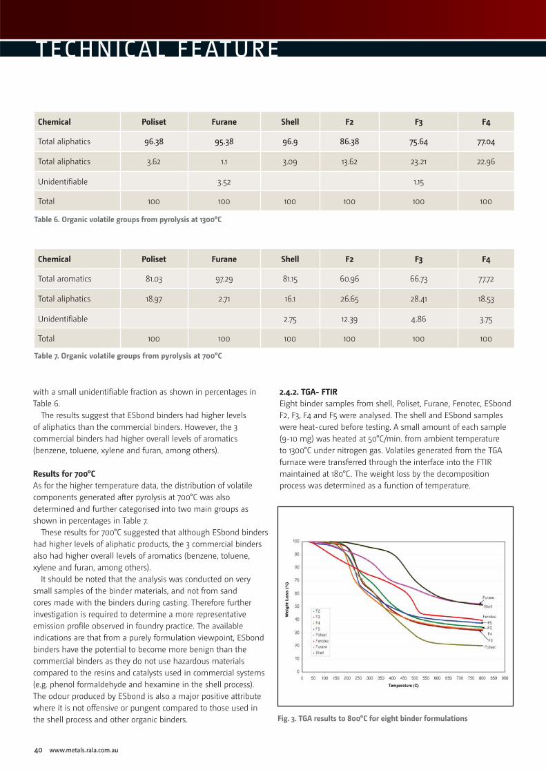
40 www.metals.rala.com.au
TECHNICAL FEATURE
with a small unidentifiable fraction as shown in percentages in Table 6.
The results suggest that ESbond binders had higher levels of aliphatics than the commercial binders. However, the 3 commercial binders had higher overall levels of aromatics (benzene, toluene, xylene and furan, among others).
Results for 700°CAs for the higher temperature data, the distribution of volatile components generated after pyrolysis at 700°C was also determined and further categorised into two main groups as shown in percentages in Table 7.
These results for 700°C suggested that although ESbond binders had higher levels of aliphatic products, the 3 commercial binders also had higher overall levels of aromatics (benzene, toluene, xylene and furan, among others).
It should be noted that the analysis was conducted on very small samples of the binder materials, and not from sand cores made with the binders during casting. Therefore further investigation is required to determine a more representative emission profile observed in foundry practice. The available indications are that from a purely formulation viewpoint, ESbond binders have the potential to become more benign than the commercial binders as they do not use hazardous materials compared to the resins and catalysts used in commercial systems (e.g. phenol formaldehyde and hexamine in the shell process). The odour produced by ESbond is also a major positive attribute where it is not offensive or pungent compared to those used in the shell process and other organic binders.
2.4.2. TGA- FTIR Eight binder samples from shell, Poliset, Furane, Fenotec, ESbond F2, F3, F4 and F5 were analysed. The shell and ESbond samples were heat-cured before testing. A small amount of each sample (9-10 mg) was heated at 50°C/min. from ambient temperature to 1300°C under nitrogen gas. Volatiles generated from the TGA furnace were transferred through the interface into the FTIR maintained at 180°C. The weight loss by the decomposition process was determined as a function of temperature.
Chemical Poliset Furane Shell F2 F3 F4
Total aliphatics 96.38 95.38 96.9 86.38 75.64 77.04
Total aliphatics 3.62 1.1 3.09 13.62 23.21 22.96
Unidentifiable 3.52 1.15
Total 100 100 100 100 100 100
Chemical Poliset Furane Shell F2 F3 F4
Total aromatics 81.03 97.29 81.15 60.96 66.73 77.72
Total aliphatics 18.97 2.71 16.1 26.65 28.41 18.53
Unidentifiable 2.75 12.39 4.86 3.75
Total 100 100 100 100 100 100
Table 6. Organic volatile groups from pyrolysis at 1300°C
Table 7. Organic volatile groups from pyrolysis at 700°C
Fig. 3. TGA results to 800°C for eight binder formulations

METAL Casting Technologies June 2011 41
The remaining weight was a measure of the residual solid products of the binder (mainly amorphous carbon) which had been formed during the thermal decomposition process and should have contributed to the residual strength of the binder.
The TGA results are given in Fig. 3. They are shown only up to 800°C as all the weight losses appear to level out after this temperature. With the exception of Poliset, the ESbond binders showed a higher weight loss compared to shell and other commercial organic binders, indicating a low residual carbon content and low residual strength after casting, thus offering a potential advantage in sand shake-out after casting.
The FTIR analysis provides relative intensities of the evolution of common volatiles. Poliset was shown to have the highest evolution intensity in phenol, benzene derivatives, naphthalene, acetone and phthalates. Shell binder has the highest intensity in ammonia, and was also very high in phenol. Furane is highest in toluene and sulphur dioxide. ESbond binders on the other hand, only produced very low levels of these volatile compounds. These compounds are potentially harmful and classified as hazardous substances to the environment (6). The TGA-FTIR analysis thus confirmed that shell and self-set binders can emit much higher levels of potentially harmful volatiles than ESbond. Fig. 4 compares typical results of the relative intensities of four volatile compounds in the six binders.
3. Experimental casting trialsEarlier work on ESbond (4) for use in sand and permanent moulds has already demonstrated its effectiveness for aluminium casting. Some testing has now been conducted for the casting of iron. In this work, hollow cores from ESbond binders and shell sand
Fig. 4. Relative intensities of the evolution of several gases from the six binder samples
Belec Metals AnalysersDesktop model, up to 24
element channels, inert gas
flushed optics, with Argon
stand. Options of ferrous
and non-ferrous bases.
Portable spectrometer with
assortment of probes. Can
be used in the field, on-site
or at metal auctions for
accurate alloy analysis.
Laboratory spectrometer,
variable configuration,
benchtop or free-standing,
many optional extras,
low Argon and power
usage. Multiple bases with
spark-stand and probe
combination available.
G & C Instrument Services P/L
Website: www.gcinstrument.com.au
Email: [email protected]
Telephone: +61 (0)2 4981 7255
Lab 3000s
Compact Port
Vario Lab

42 www.metals.rala.com.au
TECHNICAL FEATURE
process were used. Fig. 5(a) shows typical ESbond and shell cores made on the SCM and Fig. 5(b) a core located in the sand mould to produce an internal cavity in the casting.
A total of 48 cores were made, the overall size of each core being 232 mm long and the larger section diameter 56 mm. The typical weight of each core was about 0.38 kg. Under laboratory conditions, these cores were regarded as adequate in size for meaningful foundry testing. The core and casting have a similar shape to a bottomless bottle.
A total of 16 moulds were poured in an iron foundry with the ESbond and shell cores using various weight contents shown in Table 8.
Duplicate sets of moulds were used for each sand type. Gray cast iron was used at the furnace melt temperature of 1400°C. Fig. 6(a) shows the pouring of the iron castings and Fig. 6(b) the castings after fettling. The fettling was observed at the foundry and the surface conditions between the casting and core inside the hole were inspected in the lab. Each fettled casting weighed about 2.5 kg.
ESbond burnt sand from all the formulations was shown to be easy to fettle from the castings. No burn-ins or other visible surface defects were observed. ESbond sand was also shaken out as easily as shell sands at both 2% and 3.5%. On sectioned castings, the surface with ESbond sands showed that a reasonably smooth finish was obtained similar to those using shell sands.
Binders F2 F3 F4 F5 Shell
Content (%wt) 8% and 10% 10% 8% and 10% 10% 2% and 3.5%
Table 8. ESbond and shell coated sands used for cores in the casting trial
A
A
B
B
Fig. 5. ESbond and shell cores (a) and a core as located in the mould (b)
Fig. 6. Iron casting with 16 moulds in a sand foundry (a), inspection of castings after fettling, with 4 castings using shell cores in the left corner (circled), and the rest ESbond (b).
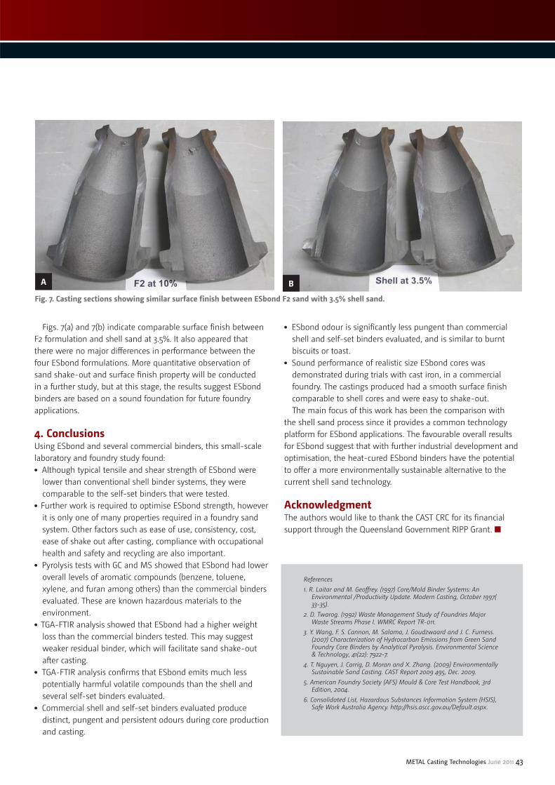
METAL Casting Technologies June 2011 43
Figs. 7(a) and 7(b) indicate comparable surface finish between F2 formulation and shell sand at 3.5%. It also appeared that there were no major differences in performance between the four ESbond formulations. More quantitative observation of sand shake-out and surface finish property will be conducted in a further study, but at this stage, the results suggest ESbond binders are based on a sound foundation for future foundry applications.
4. ConclusionsUsing ESbond and several commercial binders, this small-scale laboratory and foundry study found:● Although typical tensile and shear strength of ESbond were
lower than conventional shell binder systems, they were comparable to the self-set binders that were tested.
● Further work is required to optimise ESbond strength, however it is only one of many properties required in a foundry sand system. Other factors such as ease of use, consistency, cost, ease of shake out after casting, compliance with occupational health and safety and recycling are also important.
● Pyrolysis tests with GC and MS showed that ESbond had lower overall levels of aromatic compounds (benzene, toluene, xylene, and furan among others) than the commercial binders evaluated. These are known hazardous materials to the environment.
● TGA-FTIR analysis showed that ESbond had a higher weight loss than the commercial binders tested. This may suggest weaker residual binder, which will facilitate sand shake-out after casting.
● TGA-FTIR analysis confirms that ESbond emits much less potentially harmful volatile compounds than the shell and several self-set binders evaluated.
● Commercial shell and self-set binders evaluated produce distinct, pungent and persistent odours during core production and casting.
● ESbond odour is significantly less pungent than commercial shell and self-set binders evaluated, and is similar to burnt biscuits or toast.
● Sound performance of realistic size ESbond cores was demonstrated during trials with cast iron, in a commercial foundry. The castings produced had a smooth surface finish comparable to shell cores and were easy to shake-out.The main focus of this work has been the comparison with
the shell sand process since it provides a common technology platform for ESbond applications. The favourable overall results for ESbond suggest that with further industrial development and optimisation, the heat-cured ESbond binders have the potential to offer a more environmentally sustainable alternative to the current shell sand technology.
Acknowledgment The authors would like to thank the CAST CRC for its financial support through the Queensland Government RIPP Grant. ■
A B
Fig. 7. Casting sections showing similar surface finish between ESbond F2 sand with 3.5% shell sand.
References 1. R. Laitar and M. Geoffrey. (1997) Core/Mold Binder Systems: An
Environmental /Productivity Update. Modern Casting, October 1997( 33-35).
2. D. Twarog. (1992) Waste Management Study of Foundries Major Waste Streams Phase I. WMRC Report TR-011.
3. Y. Wang, F. S. Cannon, M. Salama, J. Goudzwaard and J. C. Furness. (2007) Characterization of Hydrocarbon Emissions from Green Sand Foundry Core Binders by Analytical Pyrolysis. Environmental Science & Technology, 41(22): 7922-7.
4. T. Nguyen, J. Carrig, D. Moran and X. Zhang. (2009) Environmentally Sustainable Sand Casting. CAST Report 2009 495, Dec. 2009.
5. American Foundry Society (AFS) Mould & Core Test Handbook, 3rd Edition, 2004.
6. Consolidated List, Hazardous Substances Information System (HSIS), Safe Work Australia Agency. http://hsis.ascc.gov.au/Default.aspx.

44 www.metals.rala.com.au
Back to B A S I C S
Hydrogen porosity
ydrogen is the only gas that is significantly soluble in aluminium and its alloys. Its solubility increases rapidly with temperature and at the melting
point an abrupt increase occurs. The solubility in solid aluminium is, however, very low so that as the alloy cools during solidification dissolved hydrogen in excess of the solid solubility limit is expelled forming the characteristic gas pores in the casting. Figures 1 & 2.
The distribution and severity of hydrogen gas voids is largely influenced by the level of dissolved hydrogen in the melt as well as the presence and size of nucleation sites such as entrained oxides and the cooling rate of the casting. Decreasing the level of hydrogen in the melt and increasing the cooling rate of the casting will suppress void formation and growth. Castings made in sand moulds are more prone to gas void formation than those made in permanent metal dies due to the lower thermal conductivity of the mould
material and subsequent slower cooling rate of sand moulded castings.
Whilst the presence of hydrogen gas voids in a casting can have a severely adverse effect on the mechanical properties of a casting this is not always the case. When the rate of solidification is high, such as in permanent metal mould diecastings, the resultant voids are generally very fine and well dispersed through the section so that any adverse effect is minimised. In such applications hydrogen gas can even have a desirable influence on the size and distribution of shrinkage porosity which is often more detrimental to casting properties. Internal shrinkage cavities require a nucleation point so impurities and dissolved gas can induce closed finely dispersed voids rather than concentrated as much larger shrinkage cavities in thermal centres. Indeed, it is a common strategy employed by diecasters with difficult to feed castings to intentionally add a controlled amount of hydrogen in order to promote superficial soundness.
Hydrogen in aluminium alloys J. F. Meredith Casting Solutions Pty Ltd
H
Figure 2. Hydrogen gas voids in aluminium casting revealed by machining.
Figure 1. Effect of temperature on the solubility of hydrogen in aluminium at 1 atm hydrogen pressure.

METAL Casting Technologies June 2011 45
Sources of hydrogenThe main sources of hydrogen are water vapour and steam originating from:● The atmosphere● Incompletely dried furnace and ladle refractories● Damp furnace tools● Furnace charge additions such as hydrated ingot and scrap● Damp fluxes● Oil contaminated turnings
To reduce the potential for pickup, refractories, furnace tools and charge material should be thoroughly preheated. As is indicated in figure 1, the temperature of the molten metal determines the amount of hydrogen absorbed, subsequently as temperature increases the amount of hydrogen taken into solution increases dramatically and so melt temperature should be kept as low as possible. Melt time and turbulence should also be minimised in order to limit exposure.
The skin of aluminium oxide that forms on the surface of liquid aluminium exposed to air can contain hydrogen. This can be a source of porosity if this oxide film becomes entrained in the melt due to turbulent tapping or pouring practice.
Removal of hydrogenBy careful attention to melting and pouring practice the amount of dissolved hydrogen in the metal can be minimised, but even with the best of practices there will be some residual level which could be detrimental to the casting.
Removal of hydrogen from the melt is generally achieved by bubbling a dry inert gas through the metal. As the gas bubbles move through the melt hydrogen diffuses into the bubbles due
to the pressure difference between the melt and the bubbles. The methods used to introduce the sparging inert gas vary from a hand-held lance fitted with a porous plug diffuser to motor driven rotary impellers with rotation speeds around 500 rpm.
Hand-held lances, even those fitted with a porous graphite diffuser tend to be limited in their effectiveness. The inert gas bubbles tend to be large and rise quickly through the melt hence limiting the amount of metal which comes in contact with the bubbles.
The rotary impeller is a much more efficient means of degassing. The gas is introduced near the bottom of the crucible and the specially designed impeller head produces a large number of very fine bubbles which saturate the melt. As these fine bubbles rise slowly through the liquid dissolved hydrogen diffuses to them and is carried to the surface and ejected to atmosphere. The rising gas bubbles also collect suspended inclusions such as oxides and carries them to the surface of the melt where they can be skimmed off. Due to the small size of the gas bubbles, rotary degassing does not generate the turbulence generally associated with lancing. The operation of a typical rotary degasser is shown schematically in figures 3 and 4 and a typical machine is shown in figure 5. ■
Figure 3. Schematic showing the operation of a typical rotary degasser
Figure 4. Schematic showing the impeller head of a typical rotary degasser
Figure 5. A typical rotarydegassing machine
Figures 3, 4 and 5 supplied by courtesy of Foseco Pty Ltd
References1. Aluminum Casting Technology 2nd Edition, American Foundrymen’s
Society 19932. Foseco Non-Ferrous Foundryman’s Handbook, 11th Edition 19993. Principles of Metal Casting, Heine, Loper & Rosethal, McGraw-Hill 1967
46 www.metals.rala.com.au
Back to the
Generalnduction furnace systems are efficient units designed with interlocks and circuit protection modules. Operators, however, should recognize all the potential
hazards involving high voltage and general foundry melting operations. The following Safety Precautions should be read carefully and properly understood by all operating and maintenance personnel and management personnel responsible for safety.
Safety precautions for operating and maintenance personnelThe purpose of this section is to familiarize operations and maintenance personnel with safety precautions that pertain to foundry operations in general and to the coreless induction melting system in particular. The safety precautions listed in this section should be observed and complied with at all times. These precautions may be considered the minimum to be followed.
It is not the purpose of this section to list every precaution which should be followed under any circumstance. Rather, these general safety precautions form a minimum set from which each installation manager can use as a base line to establish precautions and procedures suitable to his particular operations. Nothing in these precautions can substitute for properly qualified and trained operators and maintenance personnel exercising good judgment.
Copies of these safety precautions should be posted at conspicuous locations throughout the operational area of the melt system in order that operations and maintenance personnel can become thoroughly familiar with them.
General foundry precautionsThe precautions which follow here are well known to foundrymen. They are common to all metal melting operations, not only for coreless induction melting. They are offered as general precautions and should not be construed to cover all types of operations. They should be evaluated in the light of your particular operation and expanded or modified as deemed appropriate. The OSHA published Federal Regulations that are mandatory for all industries. The AFS publishes information that pertains to foundry operations only.● Access to melting and pouring operations should be limited to
authorized personnel only.● Personnel should wear safety glasses, with side shield, at all
times and should use special light reducing glasses when viewing molten metals.
● Heat and flame retardant clothing should be worn by personnel who work at or near furnaces. Clothing made of synthetic materials (nylon, polyester, etc.) should not be worn near furnaces.
● Furnace linings should be inspected frequently at regular
intervals to protect against the danger of “run-outs.” The lining should always be inspected after it cools down.
● Furnaces should be charged carefully to avoid “bridging” of the charge. Excessively high temperatures of the metal in the bath below the bridge can cause rapid erosion of the furnace lining.
● A new furnace lining must be of the correct material, compatible with the metal to be melted and should be thoroughly dry before the furnace is charged for a melt. The sintering procedure for this material must be strictly adhered to.
● Low melting point materials (such as aluminum or zinc) should be added carefully to high temperature baths (such as iron or steel). If low melting point additives submerge before they melt, they can vaporize violently and cause boil-overs or explosions.
● Charge materials should be dry and free of combustible, excessive rust, and/or liquids. Violent vaporization of liquids or combustibles can cause boil-overs or explosions in the metal bath.
● Removable crucibles should be used only for metals and furnace sizes for which they are suitable. They are not designed for the high temperatures required for melting ferrous metals. The crucible manufacturer’s specifications should be the guide for crucible use.
● When metal is transferred in a crucible, a cradle that provides adequate side and bottom support for the crucible must be used. Cradles must be provided with a means to prevent the crucible from slipping out during pouring.
● Be knowledgeable of the chemistry of your melt. Chemical reactions (such as a rapid carbon boil) can damage equipment and can be dangerous to personnel.
● Areas provided to receive runouts or spills must be kept free of accumulations of liquids. Hot metal in contact with liquids can cause violent explosions resulting in personal injuries. Other debris can prevent the flow of molten metal into the runout pit or can ignite causing a fire.
● The runout pit should be ready to receive molten metal at all times that the furnace is in operation. Runouts can occur without warning. Also, if the furnace must be emptied quickly and a ladle is not available, the furnace can be dumped right into the runout pit.
WARNING: Peersonnelel with h impllanteed ororganns, jjoinnts, plates, or simiilar objeects, sshoulld keeep aawaay frromm any induction equipmment. TThe mmagnneticc fieeldss neaear the equipmentt may innducee currrent iin anny mmetatallicc implants. Perssonnel wwith ccardiaac paacemmakkeers aree particularly at t risk annd shoould sstay wwelll awway fromm any induction equipmment.
Safety in induction furnace operations
I
By Prof. John H. D. Bautista, PEE, RMetE, MBA; Technical Consultant, Phil. Metalcasting Association., Inc.
– PART 2 –

Safety precautions for operating personnelAll induction heating and melting equipment uses potentially dangerous electrical power. The equipment is designed for safe, efficient, reliable operation and easy maintenance (if operated properly). Operator safety is enhanced by several design features built into the equipment. Deliberately ignoring these safeguards can expose the operator to hazards. The following precautions should always be observed:● Except for visual checks of the meters and lights on the outside
of the furnace cabinet, all troubleshooting, maintenance, and repair must be performed by qualified maintenance personnel. This qualified maintenance person must be able to recognize “shock hazard” and be trained in the safety precautions required to avoid possible injury or death.
● Keep all cabinet doors locked. Make keys available only to those qualified maintenance personnel who require access to the enclosures.
● Keep shield, covers, and other protective devices in place at all times during equipment operation. Exposed high-voltage equipment is a potential hazard to personnel in the work area.
● Always lock the main power disconnect in the OFF position before opening doors or removing access panels. Do not depend upon interlock devices for protection.
● Use only proven test equipment when troubleshooting a unit or components. Follow the manufacturer’s recommended procedure.
● Prevent inadvertent application of power while work is in progress in cubicles, or on furnaces, by placing warning tags and/or padlocks on main power disconnects.
● Check that ground probe wires are in contact with the furnace charge or molten metal bath every heat.
● Test the Ground Detector prior to every heat. Press, and hold in, the “TEST’ pushbutton. The leakage meter reading should decrease momentarily; the inverter will shut off, the red “CURRENT TRIP” light will turn on, and the green “GLD ON” light will turn off. If the Ground Detector does not function properly, do not operate the power supply.
WARNING: Failuure to innsuree that grouundd proobe wirres are in contact wwith the chargge or r mollten batth ccoulld lead to high volltage onn the bbath ddurinng oopereratioion. This could causse serioous injjury oor deeathh froom electrical shockk.
Power should be turned off whenever the operator must contact the molten metal bath with an electrically conductive tool - slagging tool, temperature probe, sampling ladle, etc.● Operators should wear heavy-duty, non-metallic foundry
gloves when slagging the melt, taking samples, taking temperatures, etc.
When charging the furnace ● Use only dry charge material.● Inspect bundled or baled scrap for trapped moisture before
adding it to the melt.
● Avoid charging partially closed containers (soft drink or beer cans) that could contain trapped liquids. Liquids or pieces of combustible material can vaporize with explosive violence in the melt and can cause an eruption of the molten metal.
WARNING: Failuure to ccomplyly witthh theese prooceddurees may result in ann explossion wwith pposssiblee sereriouus iinjuury to personnel.
Safety precautions for maintenance personnel● Study the maintenance procedures thoroughly.● Become familiar with the melt system and its dangerous areas
before attempting maintenance of any kind.● Never enter a module or cubicle without tagging and/or locking
the main disconnect breaker in the OFF (de-energized) position.● Always use two independent methods to support a tilted
furnace whenever working on or near it.● Use only first-class test equipment when troubleshooting a
unit and follow the manufacturer’s procedure for using the equipment.
Warning: do not touch lead eendss on aa haand d furrnacce.
● Ensure that exposed furnace leads are properly insulated at all times.
● Use proper safeguards when performing work or repairs under conditions which include high steady voltages and normal currents, or high transient voltages and currents which may result from a fault condition.
● When breakdowns or faults occur, guard against exposure to electrically live surfaces, wires, cables, and other related hazards, such as hot surfaces, rough or sharp surfaces.
● Be careful around high pressure lines, fittings, and equipment. Never tighten or loosen couplings, fittings, packings, gauges, etc., when the system is pressurized.
● Do not operate the melting system with any broken wires, loose or cracked components, hydraulic or water leakage, or electrical control malfunction.
● Supply valves (water or air) and charging valves should be opened very slowly to avoid sudden application of pressure to lines, charge tanks, or accumulators.
● The melt system equipment contains safety devices and interlocks. DO NOT defeat or bypass their purpose (except as specifically noted for troubleshooting).
● Be sure the power unit is disconnected and locked out when doing furnace maintenance. If the power unit is used to run several furnaces, disconnect the leads to the furnace being maintained from both ends of the coil and ground the coil. ■
METAL Casting Technologies June 2011 47
References1. Modern Casting Shopbook. ANSI Z241.2 – 1981 “Safety Requirements for
Melting and Pouring Metals in the Metalcasting Industry”. American Foundrymen’s Society, Inc., Golf and Wolf Roads, Des Plaines, IL 60016.
2. National Electrical Code (Latest Edition). National Fire Protection Association (NFPA) or NFPA No. 70-1978, 470 Atlantic, Avenue, Boston, MA 02210.

48 www.metals.rala.com.au
EVENTS
Aluminium China 2011When: 13-15 July 2011Where: Shanghai New International Expo Center – ChinaLocated at the very heart of industrial Asia, Aluminium China 2011 in Shanghai is dedicated to the whole supply chain in the aluminum industry and its major application fields. As part of the Industrial Materials China Events and Global Aluminium brand, Aluminium China uniquely provides access to business opportunities. Join us at Shanghai New International Expo Centre from July 13 to 15, 2011 and together we Bring Aluminum to Life!Web: http://www.aluminiumchina.com/en/
The 8th China (Beijing) International Casting Industry Exhibition ExpoWhen: 10-12 August 2011Where: China International Exhibition Center in Beijing – ChinaThe casting industry is the base of mainstay industry such as automotive, petrochemical, defence, steel, electric power, shipbuilding, textile, equipment manufacturing, etc. As an important component of manufacturing, it acts as a vital function in developing national economy and enhancing defence capacity. CIEXPO 2011 is committed to the development of the China casting industry, actively developing international casting technology communication as well as economic and trade cooperation.Web: http://www.bciffe.com/en/main asp?id=1001&classid=General
Aluminium Cast House Technology 2011When: 11–14 September 2011 Where: Sebel Albert Park Melbourne, AustraliaWith the support of the Australian and international aluminium industry, CAST CRC is organising the Aluminium Cast House Technology, 12th Australasian Conference & Exhibition. Invited and selected world recognised experts will be key speakers at the conference. Following the success of the previous eleven conferences, this conference will address the needs of the primary, secondary and recycling industries. A smelter plant tour will be held in conjunction with the conference. The Conference will also include a large trade exhibition, with major suppliers to the industry having booths to showcase their products and services.Web: http://www.aluminiumcasthouse.com/
9th Global Foundry Sourcing Conference 2011When: 23 September 2011 Where: Grand Regency Hotel, Qingdao – ChinaSeminar opportunities are provided for buyers to make special purchasing presentations, and suppliers to hold products promotion seminars. The Conference is only open to the suppliers and purchasers who register in advance. It is not available for general visitors.Web: https://www.xing.com/events/9th-global-foundry- sourcing-conference-2011-587709/description
MTM EXPO 2011 When: 26-28 September 2011 Where: The Theme Pavillion, Shanghai World ExpoOrganised by the Chinese Society for Metals, Baosteel Group Corporation and Shanghai Society of Metals, MTM EXPO 2011 will consist of Shanghai Metallurgy Expo, Shanghai Tube Expo and Shanghai Metal Expo.Email: [email protected]
AFI 2011 Queenstown Annual ConferenceWhen: 30 October – 1 November 2011Where: Millennium Hotel, Queenstown – New ZealandWith the support of the Australian and New Zealand Casting Industry, CTNZ is organising the Annual AFI Conference in New Zealand. Following the success of the previous AFI 2010 Annual Conference in Adelaide, this conference will address the needs of our industry. We have selected and invited recognised experts as key speakers. Under the Motto “Adventure with Casting” such topics as casting, foundry technology, metallurgy & thermal processing technology will be the focus. In conjunction with the conference, additional highlights include a tour of the Clyde Dam, a ‘Southern Man’ dinner event where you will be able to relax and become a Southern local for the night and a ‘Roaring Twenties’ Conference finale Banquet. The conference will also include a trade exhibition with major suppliers to the industry.Web: www.castingtechnologynz.org
The 6th Metal+Metallurgy & ThermoProcess KoreaWhen: 2-5 November 2011Where: Songdo Incheon – KoreaThis exhibition is made up of: The 6th International Heat Treatment Technology and Refractory, Furnace & Surface Finishing Equipment Exhibition Korea 2011. The 6th International Foundry, Forging and Non-metal, Die Casting Industry Equipment Exhibition Korea 2011. The 4th International ceramics and Powder-Metallurgy Industry Equipment Exhibition Korea 2011.Web: http://www.thermoprocess.com/introduction.html
ALUMINIUM India 2011When: 10-12 November 2011Where: Bombay Exhibition Centre, Mumbai - IndiaIndia’s leading B2B trade event for the aluminium eco-system and its application industries, ALUMINIUM India brings together producers, processors, technology suppliers and consumers along the entire value chain - i.e. from raw materials through to semi-finished and finished products. Now in its third edition, ALUMINIUM India 2011 aims to highlight India’s critical role in the global aluminium industry, by focusing on emerging opportunities in high growth manufacturing sectors in the South Asian region. These include Automotive Manufacturing, Building & Construction, Telecommunications, IT and Hardware. These sectors alone are capable of taking the aluminium industry in the Indian subcontinent to never before heights.Web: http://www.aluminium-india.com/index.html
The 11th Asia Foundry Congress (AFC-11) When: 12-15 November 2011 Where: Guangzhou Ocean Hotel, Guangzhou - ChinaDuring the event, foundrymen from all over the world will gather in China. The congress will be an opportunity for the international community to exchange ideas and develop a common vision for the future of world foundry industry. It will also offer a better chance for all participants to have a deeper understanding of traditional Chinese culture. Web: http://www.afc-11.com/enweb/292.html

Organised by the CAST CRC in conjunction with the Aluminium industry, related
companies. Co-sponsored by TMS USA
Peter Whiteley, Munimula Past and future of furnace technology
Michael Lampard, ABARE Status of the aluminium industry
Kelly Driscoll, CRU Cast house markets and production costs
Ray Petersen, Aleris Dross generation and processing technology: a review
Liz Swain, Rio Tinto Alcan Improving VDC casting safety and quality
Roger Lumley, CSIRO Aluminium markets and applications
Barbara Rinderer, Consulting in Partnership A review of homogenisation
Malcolm Couper, Monash University Aluminium alloys
John Grandfield, Grandfield Technology Application of modelling to casting recipe optimisation
Vu Nguyen, CAST Further developments in open mould conveyor casting
2011 KEY INVITED SPEAKERS INCLUDE:
