cast-in-place rc coupled shear walls shear wall systems 2 • rc coupled shear wall structures are a...
TRANSCRIPT

Cast-in-Place RC Coupled Shear Walls:Unbonded Post-Tensioned Coupling Beams &
Debonded Starter Bars at Wall Base
NHERI Lehigh Researcher’s Workshop
Bethlehem, PA
December 5-6, 2016
Yahya C. Kurama, Ph.D., P.E.
Steven M. Barbachyn, M.S.
University of Notre Dame
Michael J. McGinnis, Ph.D.
University of Texas at Tyler
Richard Sause, Ph.D., P.E.
Lehigh University
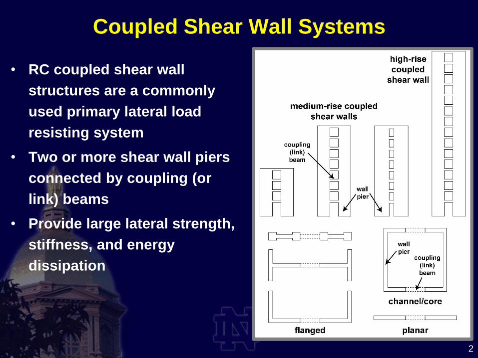
Coupled Shear Wall Systems
2
• RC coupled shear wall
structures are a commonly
used primary lateral load
resisting system
• Two or more shear wall piers
connected by coupling (or
link) beams
• Provide large lateral strength,
stiffness, and energy
dissipation

Conventional Coupling Beams
3courtesy, Magnusson Klemencic Associates
diagonal
bar groups
wall pier
wall piercoupling
beam
• Typical coupling beams are short
• Large shear force demands under large reversed-cyclic
rotations

Conventional RC Coupling Beam
Post-Tensioned Coupling Beams
4
Partially Post-Tensioned RC Coupling Beam
(Specimen 1)
unbonded PT
steel in duct
PT anchor at
end of wall pier
energy dissipating (ED)
mild steel bar with
debonded length
Fully Post-Tensioned RC Coupling Beam
(Specimen 2)
left wall pier right wall pier

Conventional RC Coupling BeamPost-Tensioned RC Coupling Beam
LOAD
large, concentrated
cracks
Post-Tensioned Coupling Beams
5

Validation & Design Process
6
• ACI 318:“...the proposed system shall have strength and toughness equal to or exceeding those provided by a comparable monolithic reinforced concrete structure satisfying this chapter.”
• Validation and Design Documents• ACI ITG-5.1 – Acceptance Criteria for Special Unbonded
Post-Tensioned Structural Walls Base on Validation Testing and Commentary
• ACI ITG-5.2 – Requirements for Design of a Special Unbonded Post-Tensioned Shear Wall Satisfying ACI ITG-5.1 and Commentary
• ACI 318 – Building Code Requirements for Structural Concrete and Commentary

Research Objectives
7
1. To develop a validated seismic design
procedure
2. To conduct system-level experimental
evaluations
3. To validate analytical models and simulation
tools that predict system behavior
4. To create a Design Procedure Document

Presentation Outline
8
• Introduction and Objectives
• Experimental Program
• Specimen 1 Details and Behavior
• Specimen 2 Behavior and Comparisons
• Conclusions

Prototype Structure
9
elevation viewplan view
prototype
core wall
lb / hb = 4.0 (Specimen 1)
= 3.0 (Specimen 2)
• Eight-Story Office Building (coupling degree=30%)
• Designed for Seismic Category D in Los Angeles, CA
• SS = 1.50; S1 = 0.60; CS = 0.136-0.154; R = 6.0; CD = 5.0
• Base Moment for Full-Scale Core Wall ~134,000-151,000 kip-ft

10
NEES Test Setup at Lehigh Univ. (40%-scale)

11
Applied 3rd Floor Drift History
Specimen 1 Specimen 2
ACI ITG 5.1 validation drift
(3% at roof)
ACI ITG 5.1 validation drift
(3% at roof)
1.5x
ACI ITG 5.1 loading protocol

Instrumentation
Type Specimen 1 Specimen 2
load cells 29 29
displacement 123 156
rotation 46 46
strain gauges 214 250
TOTAL 412 481
LVDTplastic
slides
data
acquisition
system
12

13
Digital Image Correlation (DIC)
Type Specimen 1 Specimen 2
2D systems 11 0
3D systems 3 9
TOTAL 14 9
Specimen 1 Specimen 2

Presentation Outline
14
• Introduction and Objectives
• Experimental Program
• Specimen 1 Details and Behavior
• Specimen 2 Behavior and Comparisons
• Conclusions

elevation view
cross-section
15
overlapping
small and
large hoops
adapted
ACI ITG-5.2
to design
confinement
target εmax=0.5εsu
for unbonded
length
PT steel in two
tendons near
mid-depth
shear reinf.
satisfying
ACI 318
less
confinement
due to slab
Coupling Beam Reinforcement (Specimen 1)

16
Wall Pier Reinforcement (Specimen 1)

17
Total Base Shear versus 3rd Floor Drift
(Specimen 1)
validation-level
roof drift = ±3.0%
failure due to
buckling+fracture of
starter bars at toes
coupling beams
performed well
toe region
(designed per
ACI 318-11) flan
ge
web

Reasons for Starter Bar Fracture
18
1. Lap splices above foundation
concentratedcrack at base
lack of crackingwithin splice length
wall flange
wall flange

19
Specimen 1
Reasons for Starter Bar Fracture2. Deterioration of concrete at top of foundation
increasedunsupported
length ofstarter bars
bottom hoop in pier

Presentation Outline
20
• Introduction and Objectives
• Experimental Program
• Specimen 1 Details and Behavior
• Specimen 2 Behavior and Comparisons
• Conclusions

Detail Change in Wall Pier Toes
21
Specimen 1
(per ACI 318-11)
Specimen 2
(with debonded bars)
10” unbonded
length

Coupling Beam Changes
lb
unbonded length
hb
ED
mild steel
barsfloor slab
unbonded PT
strands in ducts
mild steel
skin reinforcement
wallpier
confining hoops
hb
lb
= 4.0
lb
hb
floor slab
unbonded PT
strands in ducts
mild steel
skin reinforcement
wallpier
confining hoops
hb
lb
= 3.0
2 No. M13bars
Specimen 1
Specimen 2
22

flan
ge
web
23
Total Base Shear versus 3rd Floor Drift
(Specimen 2)
validation-level
roof drift = ±3.0%
strength loss due to
buckling+fracture of
starter bars at flanges
failure due to
buckling+fracture of
starter bars at toes
coupling beams
performed well

24
1st Story Damage Progression (Specimen 2)

wall
flange
wall
web
Comparison of Wall Pier Toe Damage
25
core wall plan view
west
pier
east
pier
Δ3,max = 3.68%
Specimen 1
Δ3,max = 2.70%Specimen 2

Coupling Beam Damage
26
west
pier
east
pier
specimen elevation view
θb,max = 10.5%

Beam End Rotations
27

Energy Dissipation
28
βh = Ad / [(E1+E1)(θ’L1+θ’L2)
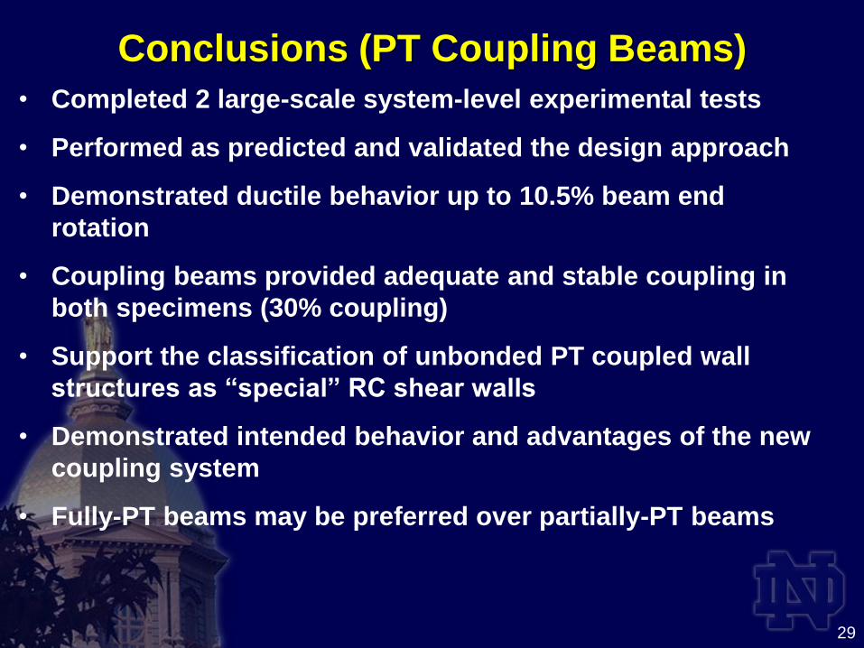
Conclusions (PT Coupling Beams)
29
• Completed 2 large-scale system-level experimental tests
• Performed as predicted and validated the design approach
• Demonstrated ductile behavior up to 10.5% beam end
rotation
• Coupling beams provided adequate and stable coupling in
both specimens (30% coupling)
• Support the classification of unbonded PT coupled wall
structures as “special” RC shear walls
• Demonstrated intended behavior and advantages of the new
coupling system
• Fully-PT beams may be preferred over partially-PT beams

Conclusions (Wall Pier Bases)
30
• Lap splices of vertical starter bars above foundation resulted
in concentration of cracking at wall base (with little
distributed cracking within spliced wall height)
• There was also significant deterioration to concrete at top of
foundation
• Failure in Specimen 1 occurred due to buckling and
subsequent fracture of starter bars in wall pier toes
• Unbonding of starter bars in toes improved behavior of
Specimen 2 by delaying buckling/fracture of starter bars
• General recommendation for RC shear walls:
consider lack of cracking over splice length of starter bars
unbonding of starter bars may delay bar fracture

Acknowledgements
31
• Project funded by NSF Grant No: 1041598
• Dr. Joy Pauschke, Program Director
• This award is part of the “George E. Brown, Jr. Network for
Earthquake Engineering Simulation (NEES) Research
(NEESR)” and the “National Earthquake Hazards Reduction
Program (NEHRP)”
• Magnusson Klemencic Associates (MKA): Dave Fields, Joshua
Mouras, Amy Haaland
• Ken Bondy, structural engineer
• Concrete Donation: Essroc Cement
• Other material donations: Dayton Superior, A.H. Harris
Construction Supplies, Hayes Industries, Sumiden Wire Products
Corporation, Suncoast Post-Tension

Acknowledgements
32
• Lehigh University
– Profs. Jim Ricles, Shamim Pakzad
– Staff: Darrick Fritchman, Peter Bryan, Gary Novak, Carl
Bowman, Thomas Maurullo, Ed Tomlinson
– Graduate Students: Michelle Tillotson, Kristen Peterson,
Karim Kazemibidokhti, Golnaz Shahidi
– Undergraduate Students:
• Katie Brinkhoff, Corey Fallon
• Mathu Davis, Amy Breden, Fannie Tao, Eric Salazar (REU)
• University of Texas at Tyler
– Graduate Student: Michelle Holloman
– Undergraduate Student: Michael Lisk

ptcoupledwalls.nd.edu
33

ptcoupledwalls.nd.edu

Conventional RC Coupling BeamPost-Tensioned RC Coupling Beam
LOAD
large, concentrated
cracks
35
Post-Tensioned Coupling Beams
Specimen 2 Specimen 1
5

36
analytical
model
test
setup
Load Application
11

wall
web
Detail Change in Wall Pier Corners
37
flan
ge
webSpecimen 1 Specimen 2
closely-spacedU-bars

Specimen 1 Specimen 2
38
Comparison of Large Drift Response

wall
flange
wall
web
Comparison of Wall Pier Corner Damage
39
core wall plan view
west
pier
east
pier
Δ3,max = 3.68%
Specimen 1 Δ3,max = 2.70%
Specimen 2


3rd Floor Drift Components (Specimen 2)
41
Specimen 2

Beam PT Stresses
42

Energy Dissipation
43