case study body control module
TRANSCRIPT
econstorMake Your Publications Visible.
A Service of
zbwLeibniz-InformationszentrumWirtschaftLeibniz Information Centrefor Economics
Daun, Marian; Fockel, Markus; Holtmann, Jörg; Tenbergen, Bastian
Research ReportGoal-scenario-oriented requirements engineering for functionaldecomposition with bidirectional transformation to controlled naturallanguage: Case study "body control module"
ICB-Research Report, No. 55
Provided in Cooperation with:University Duisburg-Essen, Institute for Computer Science and Business Information Systems(ICB)
Suggested Citation: Daun, Marian; Fockel, Markus; Holtmann, Jörg; Tenbergen, Bastian(2013) : Goal-scenario-oriented requirements engineering for functional decompositionwith bidirectional transformation to controlled natural language: Case study "body controlmodule", ICB-Research Report, No. 55, Universität Duisburg-Essen, Institut für Informatik undWirtschaftsinformatik (ICB), Essen
This Version is available at:http://hdl.handle.net/10419/75284
Standard-Nutzungsbedingungen:
Die Dokumente auf EconStor dürfen zu eigenen wissenschaftlichenZwecken und zum Privatgebrauch gespeichert und kopiert werden.
Sie dürfen die Dokumente nicht für öffentliche oder kommerzielleZwecke vervielfältigen, öffentlich ausstellen, öffentlich zugänglichmachen, vertreiben oder anderweitig nutzen.
Sofern die Verfasser die Dokumente unter Open-Content-Lizenzen(insbesondere CC-Lizenzen) zur Verfügung gestellt haben sollten,gelten abweichend von diesen Nutzungsbedingungen die in der dortgenannten Lizenz gewährten Nutzungsrechte.
Terms of use:
Documents in EconStor may be saved and copied for yourpersonal and scholarly purposes.
You are not to copy documents for public or commercialpurposes, to exhibit the documents publicly, to make thempublicly available on the internet, or to distribute or otherwiseuse the documents in public.
If the documents have been made available under an OpenContent Licence (especially Creative Commons Licences), youmay exercise further usage rights as specified in the indicatedlicence.
www.econstor.eu

�������������������
���������������������������������������������������
Marian Daun, Markus Fockel,Jörg Holtmann, Bastian Tenbergen
Case Study “Body Control Module”
ICB-Research Report No. 55
May 2013
Research Group Core Research Topics
Prof. Dr. H. H. AdelsbergerInformation Systems for Production and OperationsManagement
E-Learning, Knowledge Management, Skill-Management,Simulation, Artificial Intelligence
Prof. Dr. F. AhlemannInformation Systems and Strategic Management
Strategic planning of IS, Enterprise Architecture Management, IT Vendor Management, Project Portfolio Management, IT Governance, Strategic IT Benchmarking
Prof. Dr. P. ChamoniMIS and Management Science / Operations Research
Information Systems and Operations Research, Business Intelligence, Data Warehousing
Prof. Dr. K. EchtleDependability of Computing Systems
Dependability of Computing Systems
Prof. Dr. S. EickerInformation Systems and Software Engineering
Process Models, Software-Architectures
Prof. Dr. U. FrankInformation Systems and Enterprise Modelling
Enterprise Modelling, Enterprise Application Integration,IT Management, Knowledge Management
Prof. Dr. M. GoedickeSpecification of Software Systems
Distributed Systems, Software Components, CSCW
Prof. Dr. V. Gruhn Software Engineering
Design of Software Processes, Software Architecture, Usabi-lity, Mobile Applications, Component-based and Generative Software Development
PD Dr. C. Klüver Computer Based Analysis of Social Complexity
Soft Computing, Modeling of Social, Cognitive, and Economic Processes, Development of Algorithms
Prof. Dr. T. Kollmann E-Business and E-Entrepreneurship
E-Business and Information Management, E-Entrepreneurship/E-Venture, Virtual Marketplaces and Mobile Commerce, Online-Marketing
Prof. Dr. K. PohlSoftware Systems Engineering
Requirements Engineering, Software Quality Assurance,Software-Architectures, Evaluation of COTS/Open Source-Components
Prof. Dr. R. UnlandData Management Systems and Knowledge Representation
Data Management, Artificial Intelligence, Software Engineering, Internet Based Teaching
Prof. Dr. S. ZelewskiInstitute of Production and Industrial Information Management
Industrial Business Processes, Innovation Management,Information Management, Economic Analyses
For more information visit us on the Web: http://www.icb.uni-due.de
ISSN 1860-2770 (Print)ISSN 1866-5101 (Online)
55Goal-Scenario-Oriented Requirements Engineering for Functional Decomposition with Bidirectional Transfor-mation to Controlled Natural Language


Die Forschungsberichte des Insti tuts für Informatik und Wirtschaftsinformatik dienen der Darstel lung vorläufiger Ergebnisse, die i . d. R. noch für spätere Veröffentl ichungen überarbeitet werden. Die Autoren sind deshalb für kri t ische Hinweise dankbar.
Al l r ights reserved. No part of this report may be reproduced by any means, or translated.
Contact :
Insti tut für Informatik und
Wirtschaftsinformatik (ICB)
Universi tät Duisburg-Essen
Universi tätsstr . 9
45141 Essen
Tel . : 0201-183-4041
Fax: 0201-183-4011
Email : icb@uni -duisburg-essen.de
Authors’ Addresses:
Marian Daun
Bastian Tenbergen
paluno – The Ruhr Insti tute for Software
Technology
Universi ty of Duisburg-Essen
Gerl ingstrasse 16
D-45127 Essen, Germany
Markus Fockel
Jörg Holtmann
Project Group Mechatronic Systems
Design
Fraunhofer Insti tute for Production
Technology IPT
Zukunftsmeile 1
33102 Paderborn, Germany
The ICB Research Reports comprise prel iminary results which wil l usual ly be revised for subsequent publications. Cri tical comments would be appreciated by the authors.
Al le Rechte vorbehalten. Insbesondere die der Übersetzung, des Nachdruckes, des Vortrags, der Entnahme von Abbildungen und Tabel len – auch bei nur auszugsweiser Verwertung.
ISSN 1860-2770 (Print)
ISSN 1866-5101 (Online)
ICB Research Reports
Edited by:
Prof. Dr. Heimo Adelsberger
Prof . Dr. Frederik Ahlemann
Prof . Dr. Klaus Echtle
Prof . Dr. Stefan Eicker
Prof . Dr. Ulrich Frank
Prof . Dr. Michael Goedicke
Prof . Dr. Volker Gruhn
PD Dr. Christina Klüver
Prof . Dr. Tobias Kollmann
Prof . Dr. Klaus Pohl
Prof . Dr. Erwin P. Rathgeb
Prof . Dr. Rainer Unland
Prof . Dr. Stephan Zelewski


i
Abstract
Requirements for embedded systems are mainly documented using natural language. This is
due to the fact that natural language does not require special nomenclature knowledge and
is accepted as the basis for contractual agreements. However, purely natural-language-based
requirements engineering (RE) is often error-prone, potentially ambiguous, and does not
foster traceability and hence requires tedious manual reviews and analyses. Model-based
requirements engineering is often considered a possible solution as models enhance
traceability, aid in stakeholder communication, and foster automatic model analysis and
model checking. However, model-based requirements engineering is only slowly adopted in
the industry, partly because no clear guidelines to their application exist, particularly in
legally binding documents. In order to combine the advantages of model-based
requirements engineering with the convenience of natural-language-based requirements
engineering, we developed a combined RE approach that relies on both a controlled natural
language (i.e., a natural language that is restricted in its expressiveness) as well as
requirements models and defines a structured interface between both specification
paradigms. The purpose of this document is to report on the application of the combined
approach in an industrial case study from the automotive industry: a body control module.
A body control module is an electronic control unit (ECU) that centralizes the control of body
and comfort functions provided by multiple other ECUs distributed in a vehicle. The case
study illustrates how controlled natural language as well as requirements models can be
used in order to specify solution-neutral goal and scenario models as well as functional
requirements of a body control module across multiple layers of abstraction.

ii
Table of Content
1 INTRODUCTION ..................................................................................................................................... 1
2 RELATED WORK ...................................................................................................................................... 4
2.1 AUTOMATIC GENERATION OF MODELS FROM NL-REQUIREMENTS ........................................................ 5
2.2 GENERATING NL-REQUIREMENTS SPECIFICATIONS FROM MODELS ....................................................... 6
2.3 CONCLUSIONS FROM THE RELATED WORK ............................................................................................. 7
3 A CONTROLLED-NATURAL-LANGUAGE-BASED REQUIREMENTS ENGINEERING
APPROACH ......................................................................................................................................................... 8
3.1 METHODOLOGY ....................................................................................................................................... 9
3.2 TEXTUAL REQUIREMENT PATTERNS ...................................................................................................... 10
4 A MODEL-BASED REQUIREMENTS ENGINEERING APPROACH ......................................... 14
4.1 THE ABSTRACTION LAYER MODEL ....................................................................................................... 14
4.2 THE ARTIFACT MODEL .......................................................................................................................... 16
5 COMBINING CONTROLLED-NATURAL-LANGUAGE-BASED AND MODEL-BASED
REQUIREMENTS ENGINEERING ............................................................................................................... 20
5.1 METHODOLOGY ADAPTATION .............................................................................................................. 20
5.2 COMBINED PROCESS MODEL ................................................................................................................. 20
6 CASE STUDY: AUTOMOTIVE BODY CONTROL MODULE ...................................................... 25
6.1 COMPLETE SYSTEM LAYER ..................................................................................................................... 25
6.2 SUBSYSTEM LAYER ................................................................................................................................. 32
6.3 FUNCTION LAYER................................................................................................................................... 40
7 CONCLUSIONS AND FUTURE WORK ............................................................................................ 46
REFERENCES .................................................................................................................................................... 47

i i i
Table of figures
FIGURE 1: FUNCTION HIERARCHY DESCRIBED USING REQUIREMENT PATTERNS (BASED ON [HOLTMANN ET AL.
2011B]) .......................................................................................................................................................... 9
FIGURE 2: FROM REQUIREMENTS TO ANALYSIS MODEL (BASED ON [FOCKEL ET AL. 2012A]) ............................ 13
FIGURE 3: THE REQUIREMENTS VIEW ABSTRACTION LAYER HIERARCHY ......................................................... 15
FIGURE 4: THE ARTIFACT MODEL OF THE MB-RE APPROACH ........................................................................... 17
FIGURE 5: PROCESS FOR THE INTEGRATED METHODOLOGY ................................................................................ 21
FIGURE 6: ENVIRONMENT OF THE BODYCONTROLMODULE ON COMPLETE SYSTEM LAYER ............................. 25
FIGURE 7: GOALS ON COMPLETE SYSTEM LAYER ................................................................................................ 27
FIGURE 8: USE CASES ON COMPLETE SYSTEM LAYER ......................................................................................... 28
FIGURE 9: SCENARIO INDICATE LEFT ON COMPLETE SYSTEM LAYER .................................................................. 29
FIGURE 10: SCENARIO EMERGENCY BRAKE LIGHT CONTROLLING ON COMPLETE SYSTEM LAYER ...................... 30
FIGURE 11: SCENARIO HANDLE LEFT LAMP DEFECT ON THE COMPLETE SYSTEM LAYER ................................... 30
FIGURE 12: FUNCTION HIERARCHY ON THE COMPLETE SYSTEM LAYER ............................................................ 31
FIGURE 13: INITIAL FUNCTION HIERARCHY ON THE SUBSYSTEM LAYER ........................................................... 32
FIGURE 14: ENVIRONMENT OF THE SUBSYSTEM CONTROLTURNSIGNALS ON THE SUBSYSTEM LAYER .............. 33
FIGURE 15: ENVIRONMENT OF THE SUBSYSTEM CONTROLBRAKELIGHT ON THE SUBSYSTEM LAYER ................. 34
FIGURE 16: ENVIRONMENT OF THE SUBSYSTEM HANDLELAMPDEFECT ON THE SUBSYSTEM LAYER ................. 35
FIGURE 17: SCENARIO EMERGENCY BRAKE LIGHT CONTROLLING ON THE SUBSYSTEM LAYER ........................... 36
FIGURE 18: FUNCTIONAL INTERACTION BETWEEN THE SUBSYSTEMS ON THE SUBSYSTEM LAYER ..................... 37
FIGURE 19: FINAL FUNCTIONAL HIERARCHY ON THE SUBSYSTEM LAYER ......................................................... 37
FIGURE 20: INITIAL FUNCTION HIERARCHY ON THE FUNCTION LAYER ............................................................ 39
FIGURE 21: ENVIRONMENT OF THE FUNCTION SWITCHHAZARDLIGHTS ON THE FUNCTION LAYER ................ 40
FIGURE 22: ENVIRONMENT OF THE FUNCTION SIGNALIZEEMERGENCYBRAKE ON THE FUNCTION LAYER ....... 41
FIGURE 23: SCENARIO EMERGENCY BRAKE LIGHT CONTROLLING ON FUNCTION LAYER .................................... 41
FIGURE 24: FINAL FUNCTION HIERARCHY ........................................................................................................... 43
FIGURE 25: TIMING REQUIREMENT IN MODEL-BASED REPRESENTATION ............................................................ 44

iv
Goal-Scenario-Oriented Requirements Engineering for Functional Decomposition
1
1
Literature shows that natural language is the most common documentation format for
requirements specifications (e.g., [Juristo et al. 2002, Pretschner et al. 2007]). Partly, this is
due to the fact that requirements often become the foundation for contractual agreements
[Sikora et al. 2011], for example, between original equipment manufacturers (OEMs) and
suppliers [Jersak et al. 2003]. Using natural language has advantages for the requirements
engineering of embedded systems: on the one hand, it does not require stakeholders and
developers to become familiar with special documentation formats (e.g., formal models) and
is therefore easy to understand [Balzert 2009]. On the other hand, it typically does not
mandate dedicated documentation tools. However, there are a number of disadvantages
using natural language in requirements specifications: since it is inherently ambiguous, it can
be interpreted in different ways by the stakeholders (e.g., [Balzert 2009, Pohl 2010]), and it
cannot be easily processed using automated tools [Yue et al. 2011]. In addition, it requires
manual traceability management [Gotel and Finkelstein 1994] and the sheer volume of
requirements in some development projects impairs requirements validation significantly
[Flynn and Warhurst 1994]. One approach to tackle the problem of the inherent ambiguity of
natural language is to restrict its expressiveness by only allowing certain formulations,
phrases, and a restricted vocabulary. Such a restricted language is called a controlled natural
language (CNL) [Huijsen 1998a, Huisen 1998b, Schwitter 2010].
Using requirements models has been suggested as alleviation for the inherent problems with
natural language-based requirements specification. Using models to document requirements
is beneficial for communication among stakeholders [Pohl 2010]. In addition, models can
help to manage the complexity of the system [Neill and Laplante 2003] and can be processed
automatically. However, model-based approaches are only hesitantly adopted by the
industry partly due to the fact that there is little guidance available on when and how to use
models during the engineering of embedded systems [Sikora et al. 2012]. While some
approaches such as the SPES Modeling Framework [Broy et al. 2012] have been developed in
order to address this problem, such approaches do not take into account that models are not
considered as a suitable foundation for contractual agreements [Sikora et al. 2011].
Furthermore, it is sensible for the development process to develop the system architecture
not only based on the requirements specification, but in step with it [Nuseibeh 2001], ideally
based on a functional hierarchy, which documents required system functions [Schäuffele and
Zurawka 2003, Gausemeier et al. 2009]. This way, the architecture can be based on the
functional hierarchy, which fosters the requirements to be accurately reflected in the
architecture [Fockel et al. 2012a]. While some approaches exist which tackle the integration of
requirements and architecture, these approaches either consider a coarse development
process (e.g., [Nuseibeh 2001]), are solely model-based (e.g., [Pohl and Sikora 2007], or solely
based on (controlled) natural language (e.g., [Holtmann 2010, Holtmann et al. 2011a,

Introduction
2
Holtmann et al. 2011b]). The integration of model-based and natural-language-based
requirements engineering for the purpose of fostering the co-development of requirements
and functionality has thus far not been tackled by existing literature.
The purpose of this document is to show the application of an integrated requirements
engineering approach in an industrial case study. This RE approach makes use of both
controlled natural language and requirements models in order to combine the advantages of
both documentation formats and in order to allow for the co-development of a function
hierarchy and system requirements. The integrated requirements engineering approach
combines the pattern-based, controlled natural language requirements engineering approach
(CNL-RE approach) presented in [Holtmann et al. 2011b] with a model-based requirements
engineering approach (MB-RE approach).
The CNL-RE approach provides the ability to specify requirements such that they can be
used as a contractual basis between suppliers and OEMs. In addition, by using a strict
grammar, it prevents ambiguities for the purpose of conducting automated analyses
[Holtmann 2010] and allows structuring functionalities hierarchically.
The MB-RE approach is a seamless model-based approach to document requirements,
beginning with the system environment and coarse, solution-neutral requirements to
solution-oriented functional requirements. It relies heavily on a goal- and scenario-oriented
process and provides a number of specialized requirements model types which allow for
traceability between one another.
By combining the approaches, requirements can be elicited, agreed upon, and documented
both based on models and textually. The requirements engineer can switch between both
representations as fits best. For instance, the textual representation can be used for
document-oriented reviews or a contractual agreement with the customer, and the model-
based representation can be used to derive the system architecture as the next step in a
model-based development process.
The industrial case study presents a Body Control Module (BCM) from the automotive
domain. A BCM is an embedded system that constitutes a new paradigm in managing the
increasing number and complexity of electronic control units (ECUs) in the passenger
compartment of modern vehicles. The purpose of the BCM is to dispatch control commands,
relay sensor information, and manage data exchange between many different control units,
for example, ECUs for the power door locks, the turn signals, etc. In essence, a BCM is a
control unit for control units. The advantage of such a paradigm is that the interconnectivity
between the various control units is decreased, as every control unit only requires a
connection to the BCM, thereby leading to a reduction in the size of the cable tree inside the
vehicle. For example, rather than having to connect all four turn signals with one another to
ensure synchronous hazard flashing, the turn signals only need to be connected to the BCM
which in turn synchronizes them. On the other hand, this means that the BCM must be able

Goal-Scenario-Oriented Requirements Engineering for Functional Decomposition
3
to handle a large variety of different functions, which all have to be accounted for during
requirements engineering. That is, it must not only be able to control functions of the
individual attached systems, but it must also be able to control the attached systems in
conjunction with one another.
This paper is structured as follows: Section 2 illustrates the related work regarding the
integration of model-based and natural language-based requirements engineering
approaches. The following sections introduce the controlled-natural-language-based and the
model-based requirements engineering approaches, which were merged to an integrated
approach, respectively (Sections 3 and 4). Section 5 introduces the integrated approach
before Section 6 shows the application of the integrated approach on the automotive case
study BCM. Section 7 summarizes this document and provides an outlook on future work.
Related Work
4
2
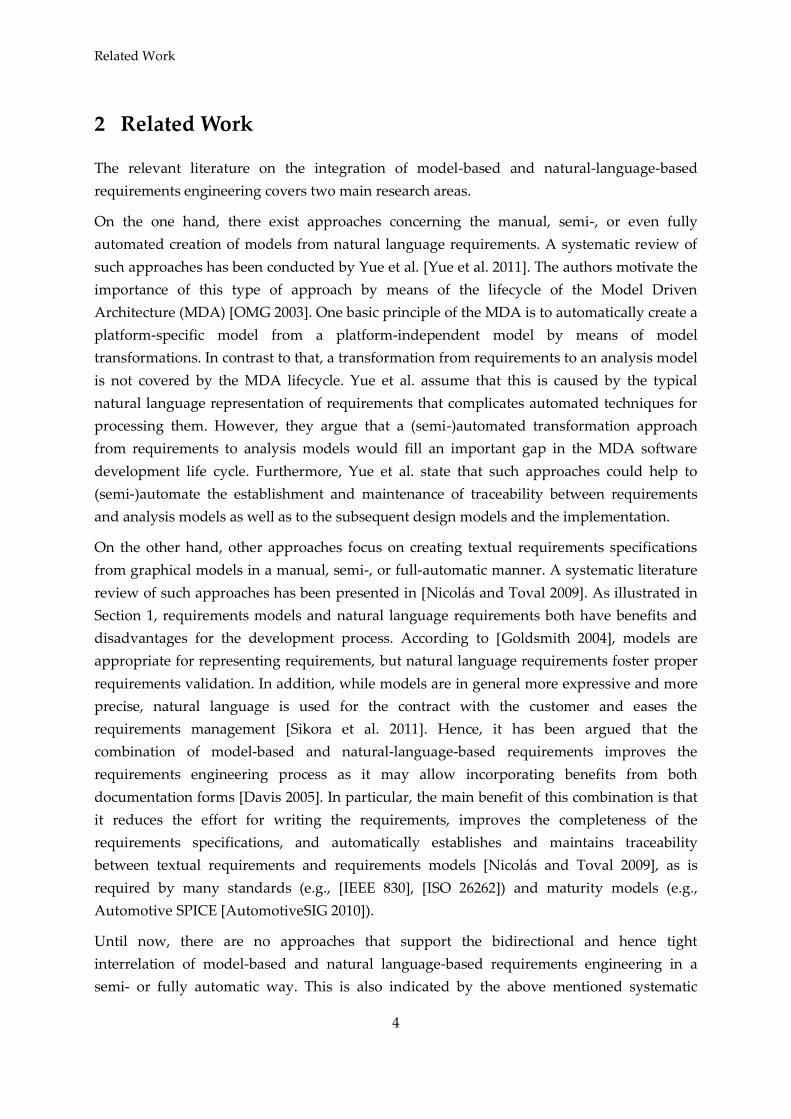
The relevant literature on the integration of model-based and natural-language-based
requirements engineering covers two main research areas.
On the one hand, there exist approaches concerning the manual, semi-, or even fully
automated creation of models from natural language requirements. A systematic review of
such approaches has been conducted by Yue et al. [Yue et al. 2011]. The authors motivate the
importance of this type of approach by means of the lifecycle of the Model Driven
Architecture (MDA) [OMG 2003]. One basic principle of the MDA is to automatically create a
platform-specific model from a platform-independent model by means of model
transformations. In contrast to that, a transformation from requirements to an analysis model
is not covered by the MDA lifecycle. Yue et al. assume that this is caused by the typical
natural language representation of requirements that complicates automated techniques for
processing them. However, they argue that a (semi-)automated transformation approach
from requirements to analysis models would fill an important gap in the MDA software
development life cycle. Furthermore, Yue et al. state that such approaches could help to
(semi-)automate the establishment and maintenance of traceability between requirements
and analysis models as well as to the subsequent design models and the implementation.
On the other hand, other approaches focus on creating textual requirements specifications
from graphical models in a manual, semi-, or full-automatic manner. A systematic literature
review of such approaches has been presented in [Nicolás and Toval 2009]. As illustrated in
Section 1, requirements models and natural language requirements both have benefits and
disadvantages for the development process. According to [Goldsmith 2004], models are
appropriate for representing requirements, but natural language requirements foster proper
requirements validation. In addition, while models are in general more expressive and more
precise, natural language is used for the contract with the customer and eases the
requirements management [Sikora et al. 2011]. Hence, it has been argued that the
combination of model-based and natural-language-based requirements improves the
requirements engineering process as it may allow incorporating benefits from both
documentation forms [Davis 2005]. In particular, the main benefit of this combination is that
it reduces the effort for writing the requirements, improves the completeness of the
requirements specifications, and automatically establishes and maintains traceability
between textual requirements and requirements models [Nicolás and Toval 2009], as is
required by many standards (e.g., [IEEE 830], [ISO 26262]) and maturity models (e.g.,
Automotive SPICE [AutomotiveSIG 2010]).
Until now, there are no approaches that support the bidirectional and hence tight
interrelation of model-based and natural language-based requirements engineering in a
semi- or fully automatic way. This is also indicated by the above mentioned systematic
Goal-Scenario-Oriented Requirements Engineering for Functional Decomposition
5
literature surveys, which only cover one direction (i.e., from natural language requirements
to models and vice versa). Moreover, we conducted a systematic literature review with
particular focus on such articles featuring semi- or fully automated approaches. In the
following, our findings are summarized with regard to the targeted use of natural language
as well as models for eliciting, documenting, reconciling, and validating requirements.
We present related approaches on (semi-)automatically generating models from natural-
language-based in the first subsection and approaches that transform model-based
requirements into natural language in the second subsection. We conclude in the last
subsection.
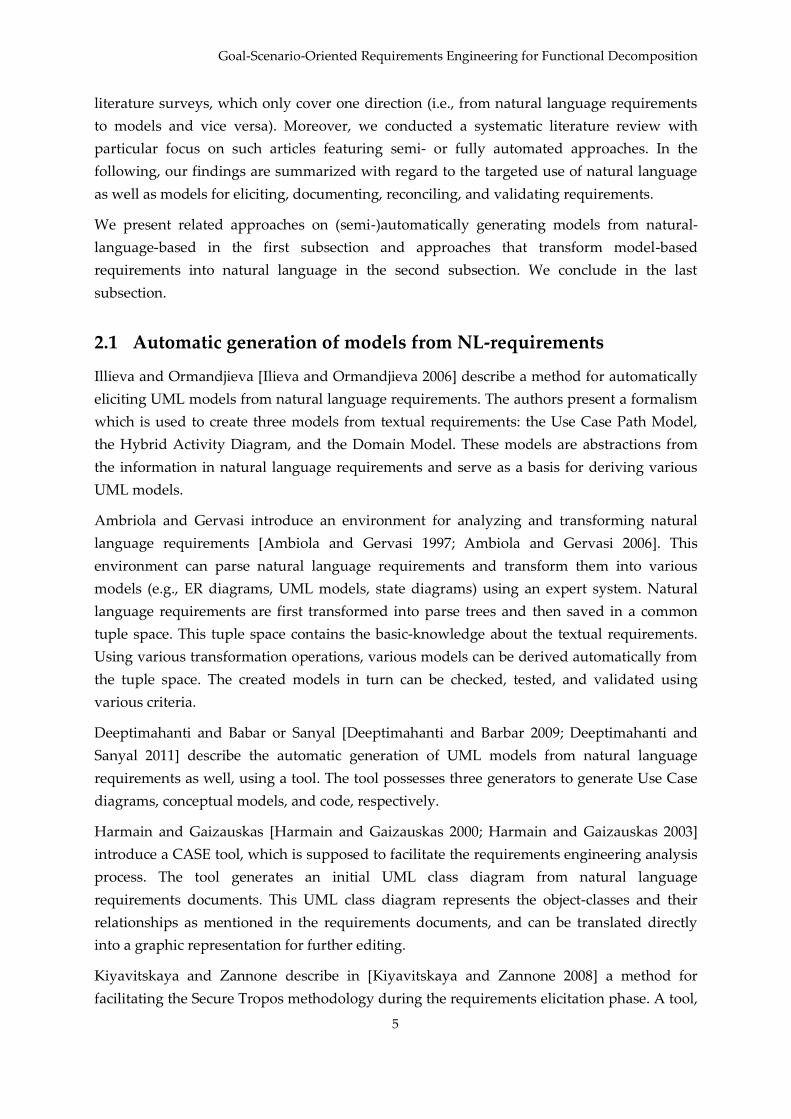
2.1 Automatic generation of models from NL-requirements
Illieva and Ormandjieva [Ilieva and Ormandjieva 2006] describe a method for automatically
eliciting UML models from natural language requirements. The authors present a formalism
which is used to create three models from textual requirements: the Use Case Path Model,
the Hybrid Activity Diagram, and the Domain Model. These models are abstractions from
the information in natural language requirements and serve as a basis for deriving various
UML models.
Ambriola and Gervasi introduce an environment for analyzing and transforming natural
language requirements [Ambiola and Gervasi 1997; Ambiola and Gervasi 2006]. This
environment can parse natural language requirements and transform them into various
models (e.g., ER diagrams, UML models, state diagrams) using an expert system. Natural
language requirements are first transformed into parse trees and then saved in a common
tuple space. This tuple space contains the basic-knowledge about the textual requirements.
Using various transformation operations, various models can be derived automatically from
the tuple space. The created models in turn can be checked, tested, and validated using
various criteria.
Deeptimahanti and Babar or Sanyal [Deeptimahanti and Barbar 2009; Deeptimahanti and
Sanyal 2011] describe the automatic generation of UML models from natural language
requirements as well, using a tool. The tool possesses three generators to generate Use Case
diagrams, conceptual models, and code, respectively.
Harmain and Gaizauskas [Harmain and Gaizauskas 2000; Harmain and Gaizauskas 2003]
introduce a CASE tool, which is supposed to facilitate the requirements engineering analysis
process. The tool generates an initial UML class diagram from natural language
requirements documents. This UML class diagram represents the object-classes and their
relationships as mentioned in the requirements documents, and can be translated directly
into a graphic representation for further editing.
Kiyavitskaya and Zannone describe in [Kiyavitskaya and Zannone 2008] a method for
facilitating the Secure Tropos methodology during the requirements elicitation phase. A tool,
Related Work
6
which is supporting the methodology, aims at translating natural language requirements in
semi-structured specifications based on the SI* modeling framework – an extension of the i*-
language for goal-modeling.
Leonid Kof describes a method for transforming natural language descriptions of interaction
sequences into automata or MSCs [Kof 2009]. This method is based on what Kof refers to as
Discourse Context Modeling for adding missing information to the natural language
specification. Furthermore, Kof describes in [Kof 2010] an interactive, adaptive CASE-tool for
facilitating processing natural language requirements. In this approach, a user marks a
sequence of words in the present text and selects a model element to which those properties
(e.g., the element’s name) are assigned that can be found in the text sequence. This creates
links between text sequences and model elements. These links serve as training sets, which
can be used to foster automatic extraction of model elements and relations.
In [Mich et al. 2002], the authors present a CASE-tool prototype for analyzing requirements,
based on processing natural language documents. The tool supports the automatic
identification of classes and the corresponding associations from textual requirements
documents and generates an abstract model. Similar to [Kof 2010], the model elements are
connected to their textual sources by introducing traceability links.
2.2 Generating NL-requirements specifications from models
In [Drusinsky 2008], a process is described that translates functional and behavioral models
such as UML activity diagrams and MSCs into natural language requirements. This
approach was developed to facilitate the increasing popularity of UML during development
and to be able to express those modeled requirements in natural language form. Similarly,
Meziane et al. introduce an approach in [Meziane et al. 2008] that derives natural language
requirements specifications from UML class diagrams. For this purpose, a system of rules is
used in conjunction with a linguistic ontology in order to express the diagram’s components.
The goal is to document the current state of the system under development in a format that is
understandable for all stakeholders.
Lu et al. [Lu et al. 2007; Lu et al. 2008b; Lu et al. 2008a] present a model-based, object-
oriented approach for eliciting and managing requirements. For this purpose, a requirements
management tool is introduced, which facilitates the integration of object-oriented concepts
and model-based requirements engineering. The principle of “modeling requirements
documents” is meant to improve completeness, consistency, and traceability as well as
integration with artifacts from other phases of the development. In addition, typical
problems of ambiguity and inconsistency in natural language documentation of
requirements can be reduced by presenting the knowledge of the pseudo-domain in an
explicit, well-defined requirements model.

Goal-Scenario-Oriented Requirements Engineering for Functional Decomposition
7
2.3 Conclusions from the Related Work
As can be seen from the literature regarding text-to-model transformation, most approaches
generate UML models like Use Case diagrams or class diagrams, either directly or via
several intermediate transformations. These various approaches are typically meant to
dissolve the inherent ambiguity in natural-language-based requirements. On the other hand,
the approaches focusing on model-to-text transformation primarily aim at facilitating the
communication with stakeholders who have no experience with models. The respective
authors of the approaches commonly agree that such methods offer good support for the
elicitation, documentation, reconciliation, and validation processes in requirements
engineering, and, moreover, they make possible to save much time and much costs. In
essence, each of the approaches presented above allow the developer to benefit from the
transition in certain development scenarios and in specific points during development.
Yet, it can be seen that no approach specifically regards the co-development of natural
language requirements and requirements models. While the approaches presented above
focus on the explicit transition either from models to text or from text to models, no approach
defines a development process that strategically incorporates the transition from models to
text and vice versa in order to make the benefits of both requirements models and natural
language requirements available throughout development.
A technical prerequisite for such a development or requirements engineering process is the
possibility of synchronization between natural language and models. It was argued in
[Nicolás and Toval 2009] that such a "synchronization could be useful in an iterative and
incremental software process”, thereby fostering validation, as validation can be “carried out
directly on the widely understandable generated textual requirements, which could be
changed to make the related models evolve automatically through traceability relationships"
[Nicolás and Toval 2009].

A Controlled-Natural-Language-based Requirements Engineering Approach
8
3 - - -
1
In previous work, we conceived a seamless, model-based design methodology for
automotive systems with focus on suppliers [Fockel et al. 2012a; Fockel et al. 2012b;
Holtmann et al. 2011a]. This automotive-specific design methodology is concerned with
requirements engineering and focuses on the formulation of requirements using natural
language, the validation of requirements and the transition to model-based design.
Our development methodology starts with so-called customer requirements [AutomotiveSIG
2010] that typically are specified informally and are made available to the supplier by an
original equipment manufacturer (OEM). These customer requirements specify the high-
level functionality of the system to be developed. Based on the customer requirements and
technical implementation knowledge, the supplier specifies more detailed system
requirements [AutomotiveSIG 2010], which propose a possible implementation of the
required system functionality.
Since requirements models are not necessarily understood by all stakeholders, their use is
not feasible in many development scenarios as contractual basis or to satisfy standards. This
is especially true for the automotive sector, which is characterized by the collaboration
between OEMs and many suppliers. Consequently, requirements specifications in the
embedded or automotive domain are typically formulated by means of natural language
[Sikora et al. 2012]. This complicates the automatic processing of the specifications. Thus,
requirements validation and the transition to model-based design have to be performed
manually, which is extensive and error-prone.
To overcome this problem, we use a Controlled Natural Language (CNL) approach for the
specification of system requirements in the automotive domain [Holtmann et al. 2011b]. The
CNL restricts the expressiveness of natural language and disambiguates it, enabling
automatic processing of the requirements while having natural language requirements
understandable for all stakeholders at the same time. We extended a CNL for the
specification of functional system requirements, which is already successfully used in the
automotive industry [Kapeller and Krause 2006].
1 This chapter bases on the previously published work ([Fockel et al. 2012a; Fockel et al. 2012b; Holtmann 2010; Holtmann et al. 2011a; Holtmann et al. 2011b]).
Goal-Scenario-Oriented Requirements Engineering for Functional Decomposition
9
3.1 Methodology
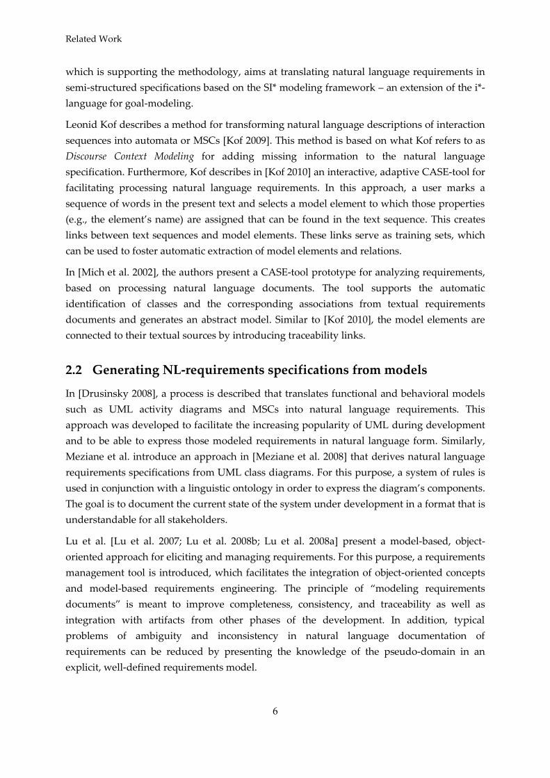
Requirement patterns are a means to describe the functionality of the system under
development (SUD), as sketched in Figure 1. The patterns allow refining the overall system
functionality across systems (i.e., a grouping of functionality) to atomic functions across
several abstraction layers. Besides the different functions, also the dependencies between
them are of interest. To identify the dependencies, the input and output data required and
provided by the different functions are analyzed and described by using the CNL in terms of
signals. The approach is similar to the Structured Analysis as presented in [Ross and
Schoman 1977; DeMarco 1979], for example. By using the requirement patterns, a function
hierarchy spanning a tree with functions as leaves is conceived. While refining the complete
system across subsystems into functions, the input and output interface of an element (i.e,
the complete system or a subsystem) of one abstraction layer is partitioned onto elements of
the next deeper abstraction layer (i.e., a subsystem or a function) in order to reduce the
overall complexity of the SUD. Concrete examples for this can be found in our case study in
Chapter 6. Furthermore, there are requirement patterns, which describe more detailed,
solution-oriented requirements as described in the next chapter and comprise quality
requirements, safety requirements, computation rules, internal states and their transitions,
and activations or deactivations of functions, for example.
Figure 1: Function hierarchy described using requirement patterns (based on [Holtmann et al.
2011b])
In the subsequent development process, a logical architecture is developed manually based
on the function hierarchy. Afterwards, the atomic leaf functions are allocated to logical
components in order to document which function is realized by which component. A
function can be allocated to one or more logical components. Alternatively, a logical
component can also realize the functionality of several functions such that a set of functions
is allocated to a single logical component (see [Fockel et al. 2012b]). The advantage of the
distinction of system functionality and architecture is that it is possible to allocate the same
functionality to different, concrete logical architectures. For example, the functionality of a
BCM for a car and for a truck is the same, but the architecture is different due to the fact that
in a truck more turn signal ECUs have to be controlled (see Chapter 6).
Function m.1.1
Subsystem 1.1
Complete
System
Input
SignalsOutput
Signals
Input
SignalsOutput
Signals
Input Signals Output Signals
Subsystem 1.nInput
Signals
Output
Signals...
Subsystem m.1Input
SignalsOutput
SignalsSubsystem m.n
Input
Signals
Output
Signals...
Function m.1.nInput
SignalsOutput
SignalsFunction m.n.1
Input
SignalsOutput
SignalsFunction m.n.x
Input
SignalsOutput
Signals... ...

A Controlled-Natural-Language-based Requirements Engineering Approach
10
3.2 Textual Requirement Patterns
The CNL consists of textual templates for requirements (requirement patterns) with static,
variable, alternative, and optional parts. The syntax is similar to that of regular expressions.
Five example requirement patterns that are relevant for this paper are listed below. Some
example requirements shaped by the requirement patterns 1–5 are listed in Table 1.
1. The system <system> consists of the following subsystem[s]: <subsystem list>.
2. The functionality of the system <system> consists of the following function[s]:
<function list>.
3. The (system <system> | function <function>) (processes | creates) the following
signal[s]: <signal list>.
4. When the event <event> occurs within the system <system> [and the condition
<condition> is fulfilled], then the function <function> is (activated | deactivated).
5. The (system <system> | function <function>) has to react within <time> <timeUnit> to
its stimuli.
In the above requirements patterns, the element <system> is a functional unit, that is, a
grouping of functionality. Thus, Complete System in Figure 1 represents the functionality of
the SUD, which is decomposed across the subsystems to atomic functions. These functions
have a behavior which can be described as a relation between the input and output signals.
The description of this behavior is not in scope of this paper and could be specified with free
natural language, with formal models, or also with a CNL.
The element signal describes the input and output data of a function. All signals are defined
in a central data lexicon (cf. the data dictionary from [DeMarco 1979]) and referenced by the
requirements shaped by the patterns. Signals specify logical values and can be used to
document the data flow between functions (e.g., velocity). Logical values are more abstract
than concrete values, which may be specified during the design of the logical and technical
architecture. For these architecture types, the interfaces are described in more detail and are
mapped to technical signals such as bus signals. Hence, the input and output signals can be
used to define interfaces in the logical and technical architecture.
ID Requirement text
R1 The system BodyControlModule consists of the following subsystems:
ControlTurnSignals, ControlBrakeLight.
R2 The functionality of the system ControlTurnSignals consists of the following
functions: Indicate, SwitchHazardLights.
R3 The functionality of the system ControlBrakeLight consists of the following functions:
LightBrakeLights, SignalizeEmergencyBrake.
R4 The function LightBrakeLights processes the following signal: brake.

Goal-Scenario-Oriented Requirements Engineering for Functional Decomposition
11
R5 The function LightBrakeLights creates the following signal: light.
R6 The function SignalizeEmergencyBrake processes the following signal:
emergencyBrake.
R7 The function SignalizeEmergencyBrake creates the following signal: lightIntense.
R8 The function SignalizeEmergencyBrake has to react within 25 ms to its stimuli.
Table 1: Example requirements specified with requirement patterns
Furthermore, requirement patterns specify events that trigger the activation or deactivation
of functions. The event specifications can be augmented by conditions that must hold in
order for the event to be triggered. These events and conditions are described with the fourth
requirement pattern. There are further templates that formalize the variables <event> and
<condition> from requirement pattern no. 4. These are listed in Table 2.
Event <signal> (increases above | decreases below | reaches) <value>
<signal> is turned (on | off)
Condition
<signal> [is] [not] (greater than | lower than | equal to | unequal to | greater
than or equal to | lower than or equal to) <value> [is]
<signal> (< | > | == | <= | >= | <>) <value>
Table 2: Templates for events and conditions
By making use of the CNL outlined above, the expressiveness of natural language is
restricted and thereby syntactically disambiguated. This fosters automatic processing of the
requirements in several ways.
Firstly, we developed a prototypical requirements editing environment consisting of a
tabular editor for the data lexicon, as well as a text editor to document the requirements
using the requirement patterns explained above [Holtmann 2010]. The text editor employs
features like error marking (e.g., in the case of text that does not correspond to the
requirement patterns), syntax highlighting, auto completion, and the automatic generation of
an overview of the current function hierarchy. These features support the requirements
engineer in a constructive manner while formulating requirements.
Second, we developed an automatic requirements validation approach on top of the
requirements editing environment [Holtmann et al. 2011b]. The validation approach
automatically checks the overall requirements specification for wellformedness w.r.t. to
predefined rules and guidelines. For example, we outlined in the last subsection that the
inputs and outputs of the atomic functions should be propagated via the subsystems to the
overall system. That is, in the final requirements specification each system should have the
union of inputs and outputs of its subordinate elements (i.e., subsystems or functions).
Regarding the requirements R3 – R7 in Table 1, the subsystem ControlBrakeLight should
process the signals brake and emergencyBrake and create the signals light and lightIntense since

A Controlled-Natural-Language-based Requirements Engineering Approach
12
the subsystem’s subordinate functions LightBrakeLights, SignalizeEmergencyBrake do so. Thus,
there should be two requirements that specify that ControlBrakeLight processes and creates
these input and output signals, respectively. Typically there is a huge amount of
requirements, which are additionally distributed across several documents and document
chapters. Thus, such missing requirements or requirement inconsistencies can easily be
missed and therefore lead to problems in the subsequent development process. Such
requirements defects can be identified by the requirements validation approach.
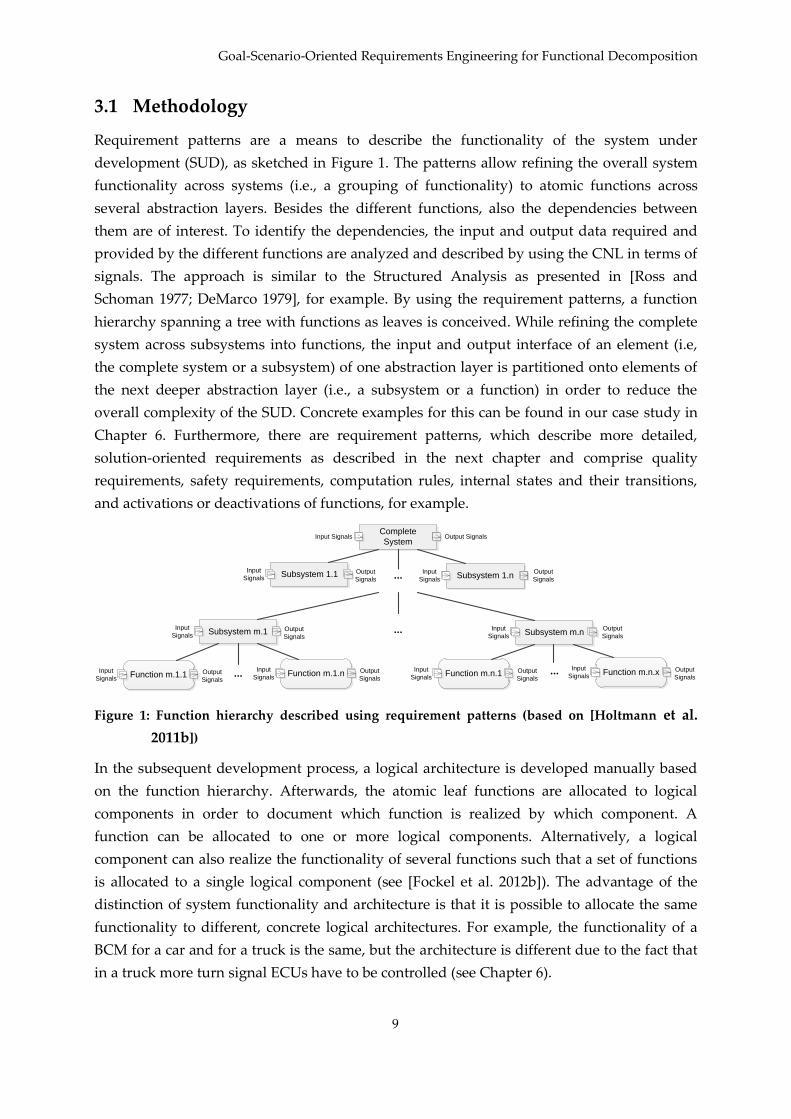
Finally, we ease the transition to model-based development by generating an analysis model
[Fockel et al. 2012a; Fockel et al. 2012b; Holtmann et al. 2011a]. The analysis model reflects
the same information as the requirements and represents the function hierarchy in a SysML
Block Definition Diagram. For example, the analysis model in the bottom of Figure 2 reflects
exactly the same information as the excerpt of requirements in Table 1. We use the analysis
model as a basis to establish traceability to the logical architecture and for detecting missing
or invalid traceability automatically [Fockel et al. 2012a]. For example, we outlined in the last
subsection that all leaf functions of the analysis model have to be allocated to logical
components in the subsequent development process. This is done by means of SysML
allocation links between the elements of the analysis model and the logical components,
amongst other things. If such trace links do not exist, we identify the corresponding
functions or logical components by automatic checks. Furthermore, we also take the relations
between the input and output information of the analysis model and the logical architecture
into account. To execute the generation, we apply the bidirectional, synchronizing model
transformation technique Triple Graph Grammars (TGGs) [Schürr 1995]. Once the analysis
model has initially been generated based on the requirements documented using the
requirement patterns explained above, TGGs allow keeping requirements and analysis
model consistent automatically. This is done by repeatedly updating the parts of the analysis
model that are affected by updated requirements. The other way round, it is also possible to
change the analysis model and update the requirements that are affected by the changes in
the model. Since TGGs store the correspondences between the analysis model and the
documented requirements (cf. objects :co1, :co2, and :co3 in Figure 2), traceability between
them is established and maintained automatically [Fockel et al. 2012a].
Goal-Scenario-Oriented Requirements Engineering for Functional Decomposition
13
Figure 2: From requirements to analysis model (based on [Fockel et al. 2012a])
bdd Analysis ModelBody
ControlModule
Control
TurnSignals
Switch
Hazard
Lights
IndicateLight
BrakeLights
Signalize
Emergency
Brakebrake
light
emergency
Brake
light
Intense
The functionality of the system
ControlBrakeLight
consists of the following functions:
LightBrakeLights,
SignalizeEmergencyBrake.
:co1
:co2
:co3
Control
BrakeLight

A Model-based Requirements Engineering Approach
14
4 -
A seamless model-based requirements engineering approach (MB-RE approach) has been
developed with the aim to foster a systematic, model-based co-design between requirements
and architecture2. The approach is based on a goal-/scenario-oriented stepwise refinement of
requirements from coarse, solution-neutral requirements to detailed, solution-oriented
requirements.
Due to the stepwise, artifact-based refinement, the MB-RE approach allows for traceability
between requirements artifacts. To enable the stepwise refinement, the MB-RE approach is
based on two main concepts: A hierarchy of abstraction layers (see Section 4.1) and a
requirements artifact model (see Section 4.2). In the following, we will summarize the key
ideas of the MB-RE approach, its requirements artifacts and architectural artifacts.
4.1 The Abstraction Layer Model
One key feature of the MB-RE approach is a hierarchy of abstraction layers. Using different
levels of abstraction is a proven way to reduce the complexity of development projects
[Weber and Weisbrod 2003] and has also been successfully applied in a number of different
research approaches (see, e.g., [Braun et al. 2010] and [Bühne et al. 2004]). The continuous
model-based requirements engineering approach therefore offers hierarchical layers of
abstraction for all requirements artifacts, which fosters the decomposition of the SUD in a
systematic manner. At each abstraction layer, a number of different requirements models are
developed: environment models, goal models, scenario models, and solution-oriented
requirements, see Section 4.2. The commonality among the requirements models on one
abstraction layer is that they contain requirements artifacts pertaining to the same set of
concerns [Fine 2002]. Abstraction layers therefore differ from one another with regard to the
level of detail of their requirements, such that some abstraction layers contain more coarsely
specified requirements (in the following, called higher abstraction layers) and some layers
contain more detailed requirements (so called lower abstraction layers).
As prior research shows (e.g., [Sikora et al. 2011]), it is futile to specify a rigid hierarchy of
abstraction layers. This is due to the vastly different development projects in individual
application domains such as automotive technology, avionics, medical, energy, or
automation technology: Building a driver assistance system in the automotive industry is
vastly different from building an assembly line in the automation industry. Consequently,
2 The requirements viewpoint presented in [Daun et al. 2012] is based on the model-based
requirements engineering approach sketched in this chapter.

Goal-Scenario-Oriented Requirements Engineering for Functional Decomposition
15
using the same abstraction layer hierarchy in both endeavors might not be wise. Therefore,
the MB-RE approach supports defining abstraction layers freely with regard to the
development project and the application domain. In other words, a particular abstraction
hierarchy must be defined according to the peculiarities that the project in the given
application domain makes necessary. Therefore, the RE approach does not define a rigid
abstraction hierarchy, but recommends a generic abstraction layer types that can be tailored
towards project and application domain. In the following, the abstraction layer types and
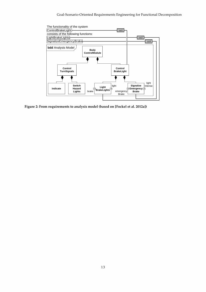
their properties and relations to one another are explained. In Figure 3, the abstraction layer
hierarchy of the MB-RE approach is illustrated.
Figure 3: The Requirements View Abstraction Layer Hierarchy
4.1.1 Top System Layer
The Top System Layer is the most abstract layer. Usually, there is only one system specified at
the Top System Layer. In this abstraction layer, the interfaces of the SUD with its
environment and entities within the environment, such as users and other systems are
captured. In addition, at this abstraction layer, physical and technical processes in the context
of the system are captured. This abstraction layer presents the services and functions offered
by the system using the artifact types outlined in Section 4.2. The requirements artifacts at
this abstraction layer focus on the system's usage, while the architecture is mainly concerned
with the definition of sub-systems.
4.1.2 System and Sub-System Layers
These layers consist of a number of different (sub-)systems that have been identified on the
next higher abstraction layer during the development of the architecture artifacts. It hence
contains the logical building blocks obtained from the decomposition of the overall system.
There may be arbitrarily many of these layers, that is, a system specified on the System Layer
may contain further sub-systems. These sub-systems are specified on the next layer, the Sub-
System Layer. Sub-systems may themselves contain further sub-systems, which are in turn
specified on the next lower sub-system layer, and so forth. Each of these layers usually
contains more than one system. Hence, in contrast to the Top System Layer, the System and
Sub-System Layers contain multiple systems. Consequently, the requirements engineering
process has to be performed for each system and sub-system and must render artifacts that

A Model-based Requirements Engineering Approach
16
are both consistent to one another (i.e., to the artifacts of other systems within this layer) and
to the next higher layer.
4.1.3 Component Layer
The Component Layer is usually the lowest abstraction layer, disregarding from how many
sub-system layers have been defined. This layer is largely similar to the sub-system layer(s).
The main difference between System, Sub-System, and Component Layer is that the sub-
systems specified at the Component Layer are not decomposed any further. Sub-systems that
are not decomposed are considered atomic components. The Component Layer consists of
hardware and software components that realize the entire system's properties. At this layer,
the interrelation between software and hardware components is defined. Therefore, this
layer ordinarily contains the physical building blocks of the entire system.
4.1.4 Using Abstraction Layers
There is no restriction regarding how many or how few abstraction layers must be defined.
For example, if a very simple system is to be designed that is not further decomposed into
sub-systems or components, or if the complexity of the system does not significantly
decrease due to decomposition into sub-systems, the requirements engineer might choose to
use merely one abstraction layer. This would be equivalent with specifying the system under
development on the Top System Layer. On the other hand, it is also possible to use two or
more abstraction layers. Using two abstraction layers is equivalent to specifying the
requirements on the Top System Layer and Component Layer, respectively. In the case that
more than two abstraction layers are used, requirements are also specified on at least one
System Layer.
4.2 The Artifact Model
Research in model-based requirements engineering must provide RE approaches that do not
only give methodological guidance with regard to the use of abstraction, but also with
traceability and consistency of requirements artifacts that are specified during the RE process
[Sikora et al. 2011]. In other words, it must be possible to trace requirements artifacts
throughout the development process [Gotel and Finkelstein 1994]. By means of the stepwise
refinement of requirements artifacts on different layers of abstraction (see Section 4.1), the
MB-RE approach provides one way to achieve both traceability and consistency. One further
device to ensure traceability and consistency in this model-based requirements engineering
approach is the inherent artifact model. Artifacts types used in this approach are
environment models, solution-neutral requirements, that is, goal and scenario models,
solution-oriented requirements models in the perspectives behavior, function, and data, as
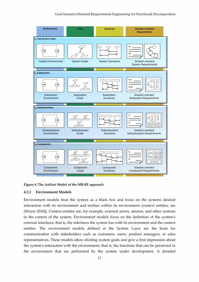
well as architecture models. In the following, we briefly explain the different artifact types of
the RE approach shown in Figure 4.
Goal-Scenario-Oriented Requirements Engineering for Functional Decomposition
17
Figure 4: The Artifact Model of the MB-RE approach
4.2.1 Environment Models
Environment models treat the system as a black box and focus on the systems desired
interaction with its environment and entities within its environment (context entities, see
[Weyer 2010]). Context entities are, for example, external actors, sensors, and other systems
in the context of the system. Environment models focus on the definition of the system's
external interfaces, that is, the interfaces the system has with its environment and the context
entities. The environment models defined at the System Layer are the basis for
communication with stakeholders such as customers, users, product managers, or sales
representatives. These models allow eliciting system goals and give a first impression about
the system's interaction with the environment, that is, the functions that can be perceived in
the environment that are performed by the system under development. A detailed
Environment Scenarios Solution-orientedRequirements
Goals
L1 Top System Layer
System ScenariosSystem Goals Solution-oriented
System Requirements
R1
RN
System Environment
L3 Subsubsystems
Subsubsystem
Scenarios
Subsubsystem
Goals
Solution-oriented
Subsubsystem Requirements
R…
R…
Subsubsystem
Environment
Ln Components
Component
Scenarios
Component
Goals
Solution-oriented
Component Requirements
R…
R…
Component
Environment
L2 Subsystems
Subsystem
Scenarios
Subsystem
Goals
Solution-oriented
Subsystem Requirements
R1.1
R1.M
Subsystem
Environment
A Model-based Requirements Engineering Approach
18
description of context models can be found in [Weyer 2010]. Structural diagrams such as
SysML Internal Block Diagrams can be used to model this artifact type.
4.2.2 Solution-neutral requirements
Solution-neutral requirements are used to document rationales for solution-oriented
requirements. There are two types of solution-neutral requirements: goal models and
scenario models.
Goal models document the intentions that the stakeholders have when conceiving the system
and can sketch alternative realization options. In early requirements engineering, using goal
models helps to focus on identifying the problems and exploring the system solutions and
alternatives. Goals form a first manifestation of the vision about the system that the
stakeholders have in mind. Goals are solution-neutral descriptions of the functionalities,
qualities, and features the system under development must possess. Goals neglect concrete
aspects of the solution. In goal models, relationships between goals, functionalities, and
qualities can be identified. For example, goals might be in direct conflict with each other (i.e.,
fulfilling one goal will make it impossible to fulfill a conflicting goal) or the fulfillment of
goals may contribute—positively or negatively—to the fulfillment of another goal (i.e., make
it easier or harder to achieve the other goal). Goals can be elicited, in part, from the
environment model, but also by means of stakeholder collaboration. The MB-RE approach
differentiates between hardgoals, that is, goals whose fulfillment can be unambiguously
verified (e.g., by yes/no questions), and softgoals, which are goals whose fulfillment depends
on some degree of interpretation (e.g., goals pertaining to the quality aspect “usability”).
Goals and goal modeling is explained in detail in [Pohl 2010] as well as [van Lamsweerde
2009]. KAOS goal diagrams, i* models, or stereotyped SysML Requirements Diagrams can be
used to model this artifact type.
Scenario models are exemplary interactions of the system with its environment. Scenarios
allow eliciting requirements by modeling the system's interaction with context entities that
have been identified in the environment models. Thereby, the system's benefit and impact on
the environment can be assessed. Scenarios fulfill the goals that have been specified in the
goal models. For every goal, there must be at least one scenario that fulfills it and every
scenario must fulfill at least one goal. Furthermore, scenarios may specify some internal
states, albeit the state space of the system under development can usually not be fully
modeled using scenarios. This is due to the fact that scenarios merely model exemplary
interactions of the system with its environment, rarely all interactions. Scenario modeling is
described in detail in [Pohl 2010] as well as [Potts 1995]. Additionally, alternative and error
handling scenarios can be specified that describe exceptional interactions deviating from the
main scenarios. SysML Use Case and Sequence Diagrams as well as ITU Message Sequence
Charts can be used to model this artifact type, for example.
Goal-Scenario-Oriented Requirements Engineering for Functional Decomposition
19
4.2.3 Solution-oriented requirements
Solution-oriented requirements are solution-specific descriptions of behavior, functions, and
data (the three perspectives, see [Pohl 2010] and [Davis 1993]) and thus represent a first step
towards the implementation. Solution-oriented requirements consist of data models,
functional models, and state models which represent the data, function, and behavior
perspective, respectively. Solution-oriented requirements can in insofar be derived from
scenario descriptions as scenarios may specify states that the system adopts after a certain
interaction sequence has been executed. Furthermore, on the basis of scenarios and
environment models, the function perspective of solution-oriented requirements can be
derived in part. All three perspectives of solution-oriented requirements are co-developed, as
they present individual views onto the same system. A more detailed explanation of
solution-oriented requirements is given in [Pohl 2010]. SysML Block Definition Diagrams are
used for the data perspective, SysML Activity Diagrams are used for the function
perspective, and SysML State Machine Diagrams are used for the behavior perspective to
model solution-oriented requirements.
4.2.4 Combining solution-neutral and solution-oriented requirements across
Abstraction Layers
Goal- and scenario-oriented RE approaches appear to be considered a beneficial approach for
practitioners [van Lamsweerde 2009] as an essential component involved in the
requirements engineering process. Typically, in goal- and scenario-oriented approaches, the
context is analyzed, problems are identified, and high level strategic goals for developing a
system to solve the problems are elicited. Consequently, solution-oriented requirements are
specified to fulfill these goals. Thus, goals are guiding the requirements elicitation process
and are identified on the basis of environment artifacts. However, goals merely reflect an
idealized view of the desired context, that is, depict a desired state of the system after
development. Thus, requirements elicitation should not rely only on goals. It needs a
combination with another facilitating option which should give some information of current
reality. For this purpose, scenarios can be used which represent sequences of real events in
the context. Solution-oriented requirements are specified on the basis of goals and scenarios
and build the immediate input for architecture models. Developing these artifacts for some
system, sub-system, or component on some abstraction layer is in principle a sequential
process. However, during the requirements engineering process, particular attention must be
placed on maintaining consistency between the requirements artifacts. While the
relationships between these artifacts as explained above already allow for traceability and
consistency, consistency checks must be performed whenever an artifact is completed so that
the artifacts do not contradict one another. For example, behavior models as well as scenario
models must be checked for consistency across abstraction layers in order to ensure that the
scenarios specified on the lower abstraction layers are correct refinements of the scenarios on
the higher abstraction layer (cf. [Sikora et al. 2010]).

Combining Controlled-Natural-Language-based and Model-based Requirements Engineering
20
5 - - -
-
Informal requirements can be formulated and formalized by means of requirement patterns
using the controlled-natural-language-based RE (CNL-RE) approach illustrated in Chapter 3.
While natural language is the preferred documentation format for legally binding
requirements documents and for document-oriented reviews, there is a tendency and desire
among requirements engineers to use models during the RE process [Sikora et al. 2012]. For
this reason, we integrate the CNL-RE approach shown in Chapter 3 with the model-based RE
(MB-RE) approach explained in Chapter 4. This enables to switch the documentation format
at certain points in time. In the remainder of this section, we present the basic methodology
of the integrated approach. In Chapter 6, we evaluate the applicability of the approach by
means of the case study “Body Control Module”.
5.1 Methodology Adaptation
In order to integrate the CNL-RE and the MB-RE approach, we adapted the methodology of
the latter one. The key change is that all artifacts describe a functional view of the SUD as in
the CNL-RE approach. Furthermore, the use of scenarios of the MB-RE approach enables to
conceive the function hierarchy of the CNL-RE approach in a more systematic way. Based on
this functional view, the logical architecture of the SUD is developed as outlined in the
Chapter 3. This is explained in more detail in the following section.
5.2 Combined Process Model
Figure 5 shows the integrated methodology. The color scheme in Figure 5 is based on the
color scheme in Figure 4, yet has been extended to depict activities that produce artifacts
based on the controlled-natural-language-based component of the combined RE approach.
That is, the red activities 5 and 10 regarding the function hierarchy of the SUD. Furthermore,
some artifacts of the MB-RE approach can alternatively be represented by means of
requirement patterns, see activities 6 and 11.

Goal-Scenario-Oriented Requirements Engineering for Functional Decomposition
21
Figure 5: Process for the integrated methodology
As it can be seen from Figure 5, the integrated methodology is divided into two parts. First,
the functionality of the SUD is considered in its entirety on the so-called complete system layer
act [Activ ity] NLRE-MBRE [Combined process]
2. Specify goals (KAOS)
1. Describe env ironment
(SysML bdd)
3. Determine use cases
(SysML ucd)
9. Refine scenarios
(SysML sd)
7. Limit env ironment
(SysML ibd)
Subsystem Layers
and Function LayerComplete System Layer
4. Specify scenarios
(SysML sd)
5. Deriv e function
hierarchy (SysML bdd /
requirement patterns)
6. Specify
solution-oriented
requirements (SysML /
requirement patterns)
8. Refine goals (KAOS)
11. Add solution-oriented
requirements (SysML /
requirement patterns)
10. Decompose function
hierarchy (SysML bdd /
requirement patterns)
[Function hierarchy
refined because
subsystems were not
sufficiently trivial]
[else]

Combining Controlled-Natural-Language-based and Model-based Requirements Engineering
22
(cf. the complete system in Section 3.1 and the Top System Layer in Section 4.1). Similarly to
the methodology of the CNL-RE approach (cf. Section 3.1), the system layer is refined across
several subsystem layers to the deepest function layer afterwards. In the following, we
explain the particular steps of the methodology in more detail.
Please note that the steps 7 through 11 may be repeated for any subsequent abstraction layer.
Furthermore, Figure 5 as well as our case study could be interpreted in such a way, that only
a sequential requirements engineering process similar to the waterfall model for the whole
software development process [Royce 1970] is allowed. But, of course, iterations are
explicitly allowed in our RE process.
5.2.1 Step 1: Describe Environment
First of all, the environment of the SUD is described. From the viewpoint of a supplier, the
environment typically consists of other ECUs of the car. The environment has to be
determined based on the informal customer requirements of the OEM. The key difference to
the MB-RE approach is that the context of the SUD (i.e., its environment) is considered in a
purely functional manner. That is, we model no concrete ECUs but their functionalities,
which are required or requested by the SUD. The system environment is described by means
of a SysML Internal Block Diagram.
5.2.2 Step 2: Specify Goals
In the second step, the goals of the SUD are specified. These goals are not always known to a
supplier that has to develop a system for an OEM. In this case, the goals have to be
determined based on the customer requirements. In the ideal case, the OEM additionally
forwards the goals together with the customer requirements to the supplier. As in the MB-RE
approach, the goal artifacts are modeled using KAOS goal diagrams [van Lamsweerde 2009].
In order to achieve UML-/SysML-compliant artifacts, we apply stereotyped UML class
diagrams as concrete notation for the KAOS goal diagrams.
5.2.3 Step 3: Determine Use Cases
Third, the use cases of the SUD are determined based on the customer requirements. They
are documented by means of use case diagrams like in the model-based RE approach.
5.2.4 Step 4: Specify Scenarios
In the fourth step, the use cases are described in a more detailed way using scenarios. All
information needed for modeling the use cases and scenarios is determined based on the
customer requirements and the goals the scenarios have to fulfill. The interacting objects are
elements of the environment that has been specified in step 1. Each scenario is modeled by
means of a sequence diagram.

Goal-Scenario-Oriented Requirements Engineering for Functional Decomposition
23
5.2.5 Step 5: Derive Function Hierarchy
In this step, the functionality of the SUD is decomposed into subsystems (cf. Chapter 3).
These subsystems are decomposed in the following iterations until the function layer is
reached (cf. Step 11). This layer contains the atomic functions. Therefore, as explained in
Chapter 3, this decomposition results in a function hierarchy. This step specifies function
hierarchies based on the scenarios specified in Step 4 in a manner consistent with the CNL-
RE approach (cf. Section 3.1). As in the CNL-RE approach, the model-based representation of
the function hierarchy is specified by means of a SysML Block Definition Diagram.
5.2.6 Step 6: Specify Solution-oriented Requirements
Solution-oriented requirements for the complete system can be specified in this step using
the textual requirement patterns of the CNL-RE approach. As explained in Chapter 3, the
patterns encompass besides the description of the SUD functionality also quality and safety
requirements, computation rules, internal states and their transitions, and activations or
deactivations of functions, for example. Typically, these solution-oriented requirements are
formulated in deeper abstraction layers. In this integrated methodology, only the functional
perspective of solution-oriented requirements is being considered as it serves as the basic
input for the decomposition using requirement patterns. The behavioral and structural
perspective can also be specified in addition, but the focus of this combined approach is on
system functions.
5.2.7 Step 7: Limit Environment for each Subsystem on the next Abstraction Layer
In this step, the environment that was specified on the preceding (sub)system layer is cut
down on those elements that are relevant to the subsystems of the currently considered
layer. Each subsystem is considered individually. The other subsystems on the same layer,
which are interacting with the considered subsystem, are as well regarded as functionalities
of the environment. This is specified by means of a SysML Internal Block Diagram as in the
environment description of the complete system layer.
5.2.8 Step 8: Refine Goals for each Subsystem on the next Abstraction Layer
If necessary, the specified goals are refined for the subsystems, which have been newly
added to the function hierarchy. Furthermore, new goals can be added to the initial class
diagram derived from step 2.
5.2.9 Step 9: Refine Scenarios for each Subsystem on the next Abstraction Layer
The scenarios of the superordinate (sub)system layer are refined in this step. To do so, the
superordinate (sub)system(s) are replaced by the subsystems or functions, which have been
newly added at the currently considered layer. The message exchange is adapted
accordingly. As in step 4, sequence diagrams are applied for the specification of the
scenarios.

Combining Controlled-Natural-Language-based and Model-based Requirements Engineering
24
5.2.10 Step 10: Decompose Function Hierarchy
If the subsystems newly added at the previous layer of abstraction can be decomposed, this
is done in this step by further decomposing them in the SysML Block Definition Diagram
representing the function hierarchy. In this case, a new subsystem layer is conceived. A
subsystem is trivial, if all relevant stakeholders have a sufficient understanding about the
subsystem’s functionality without further decomposition. In this case, the subsystems
represent atomic functions, which do not need to be decomposed any further. Thus, the
currently considered layer is the function layer, and the requirements engineering process is
completed after step 11.
Since we conceived a correlation—formalized using bidirectional TGG model
transformations—between the function hierarchy (cf. the analysis model in Chapter 3) and
Natural-Language-based requirements formulated by means of requirement patterns, we
can automatically transfer the function hierarchy to textual requirements. This is especially
important in the case of reviews that typically impose a document-oriented structure.
Furthermore, if changes occur in the textual review version, these changes can automatically
be transferred to the function hierarchy again.
5.2.11 Step 11: Add Solution-oriented Requirements for each Subsystem on the next
Abstraction Layer
If further solution-oriented requirements are identified while refining the functionality of the
SUD, they are formulated by means of requirement patterns in this step.
If the function layer was reached in step 10 (i.e., the subsystems were not decomposed any
further), the process is completed.
5.2.12 End of Process
After the requirements engineering process has been completed, the resulting function
hierarchy as well as the solution-oriented requirements can be transferred to the final system
requirements specification document.
Based on the function hierarchy, a logical architecture is manually conceived at the end of
the requirements engineering process. The traceability between the atomic functions of the
function hierarchy and the logical components is documented by SysML allocation links
([Fockel et al. 2012a]; [Fockel et al. 2012b]).
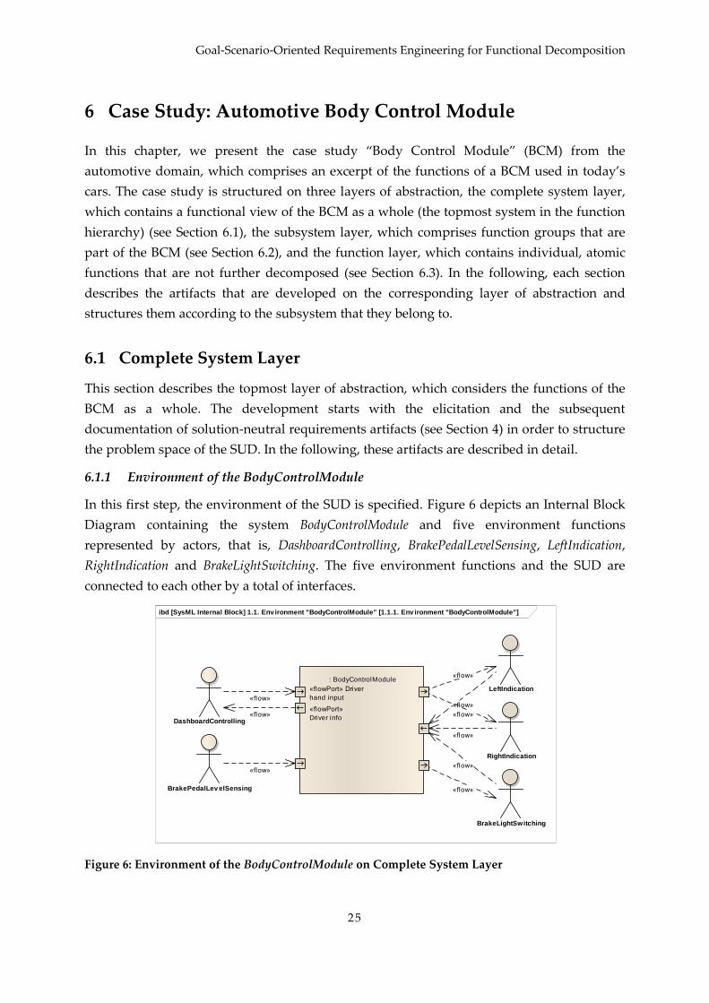
Goal-Scenario-Oriented Requirements Engineering for Functional Decomposition
25
6
In this chapter, we present the case study “Body Control Module” (BCM) from the
automotive domain, which comprises an excerpt of the functions of a BCM used in today’s
cars. The case study is structured on three layers of abstraction, the complete system layer,
which contains a functional view of the BCM as a whole (the topmost system in the function
hierarchy) (see Section 6.1), the subsystem layer, which comprises function groups that are
part of the BCM (see Section 6.2), and the function layer, which contains individual, atomic
functions that are not further decomposed (see Section 6.3). In the following, each section
describes the artifacts that are developed on the corresponding layer of abstraction and
structures them according to the subsystem that they belong to.
6.1 Complete System Layer
This section describes the topmost layer of abstraction, which considers the functions of the
BCM as a whole. The development starts with the elicitation and the subsequent
documentation of solution-neutral requirements artifacts (see Section 4) in order to structure
the problem space of the SUD. In the following, these artifacts are described in detail.
6.1.1 Environment of the BodyControlModule
In this first step, the environment of the SUD is specified. Figure 6 depicts an Internal Block
Diagram containing the system BodyControlModule and five environment functions
represented by actors, that is, DashboardControlling, BrakePedalLevelSensing, LeftIndication,
RightIndication and BrakeLightSwitching. The five environment functions and the SUD are
connected to each other by a total of interfaces.
Figure 6: Environment of the BodyControlModule on Complete System Layer
ibd [SysML Internal Block] 1.1. Env ironment "BodyControlModule" [1.1.1. Env ironment "BodyControlModule"]
DashboardControlling
BrakePedalLev elSensing
BrakeLightSwitching
«flowPort» Driver
hand input
«flowPort»
Driver info
: BodyControlModule
«flowPort» Driver
hand input
«flowPort»
Driver info
LeftIndication
RightIndication
«flow»
«flow»
«flow»«flow»
«flow»
«flow»
«flow»
«flow»
«flow»
Case Study: Automotive Body Control Module
26
As can be seen in Section 4, environment models describe the embedding of the SUD into its
environment. Relevant functions within the environment of the SUD are identified and their
inputs into the SUD and the outputs from the SUD that they receive are documented. Each
input or output constitutes an interface of the SUD with the context. In consequence, the
environment models serve as the foundation for further development activities, such as goal
elicitation (see Section 6.1.2). The key difference to the MB-RE approach is that the context of
the SUD is considered in a purely functional manner. For example, the model contains an
environment function DashboardControlling instead of a concrete ECU
HumanMachineInterface.
While the system BodyControlModule represents the overall functionality of the SUD (cf.
Chapter 3), the purpose of the environment functions is the following:
The function DashboardControlling provides the BCM with the current position of the
turn signal lever, information about the status of the hazard lights button, and means
to light LEDs in the dashboard as feedback to the driver.
The function BrakePedalLevelSensing provides the BCM with the current position of
the brake pedal.
The functions LeftIndication and RightIndication control the left and right turn signals,
respectively.
The function BrakeLightSwitching allows lighting the car’s brake lights.
The concrete signals of the functions are not yet considered in this step but in the Sections
6.1.3 and 6.1.4. In the next step, the goals that the environment functions expect the SUD to
fulfill can be derived based on information of this environment model.
6.1.2 Goals on Complete System Layer
In the second step, the goals for the SUD are specified within a goal diagram.
In Figure 7, a goal diagram describing the refinement of BCM goals in its subgoals is shown.
Legal regulations shall be fulfilled and rear-end collisions shall be avoided by means of the
turn signal and brake light control. Thus, the two root goals Fulfillment of legal regulations and
Avoidance of rear-end collision are refined by the goals Notify of change in direction, Notify of
slowdown and Notify of dangerous situation. In subsequent steps, the indication of a direction
change can be realized by a turn signal control, and the notification of a slowdown can be
realized by a brake light control. The goal Notify of dangerous situation is refined by the goals
Notify of emergency braking and Notify of danger by halting. Dangerous situations caused by a
vehicle standstill (e.g., a car broken down or at the tail end of a traffic jam) can be indicated
by using the hazard lights. An emergency brake shall be indicated by lighting the brake
lights intensely and additionally activating the hazard lights.

Goal-Scenario-Oriented Requirements Engineering for Functional Decomposition
27
Figure 7: Goals on Complete System Layer
As described in Section 4.2.2, goals can be divided in hardgoals and softgoals. In the
example, it is possible to verify that the legal regulations are fulfilled or that an emergency
brake is successfully indicated. But, of course it is not possible to verify that the BCM avoids
rear-end collisions for the whole lifecycle of all cars that have the BCM build in, since the car
driver as well as the environment is another important factor w.r.t. collisions, for example.
Thus, the goal Avoidance of rear-end collision is a softgoal.
Furthermore, the goal Notify of slowdown is a positive contribution for the goal Notify of
emergency braking (indicated by the ++), since an emergency brake is a form of a slowdown,
too. If the goal Notify of slowdown is already fulfilled, then the goal Notify of emergency braking
is easier to fulfill. Negatively contributing goals are not included in this case study.
6.1.3 Use Cases and Scenarios on Complete System Layer
In the third step, the use cases and scenarios of the SUD are determined on the basis of the
informal requirements, the environment model, and the goals specified in the last step.
In Figure 8, a use case diagram is given, which is used to structure the scenario models. In
this example, the use cases Indicate left, Indicate right, and Switch hazard lights are specified for
functionality w.r.t. the turn signals. The environment function DashboardControlling
participates in these use cases. The environment functions LeftIndication and RightIndication
participate on the use cases Switch hazard lights, Indicate left, and Indicate right.
class 1.2.1. Goals "BodyControlModule"
<< hardgoal >>
Notify of change in direction ()
<< hardgoal >>
Notify of dangerous situation ()
<< hardgoal >>
Notify of danger by halting ()
<< hardgoal >>
Notify of slowdown ()
<< softgoal >>
Avoidance of rear-end collision ()
<< hardgoal >>
Fulfi lment of legal regulations ()
<< hardgoal >>
Notify of ermergency braking ()
«Refined By»
«Refined By»
«Refined By»
«Refined By»
«Refined By»
«Refinement Of»
++
«Contribution»
«Refined By» «Refined By»
«Refinement Of» «Refinement Of»
«Refined By»

Case Study: Automotive Body Control Module
28
Figure 8: Use Cases on Complete System Layer
Furthermore, there are the use cases Brake light switching and Emergency brake light controlling
w.r.t. the functionality of the brake light. The environment functions BrakePedalLevelSensing
and BrakeLightSwitching participate on both these use cases. As can be seen from the use case
diagram, the scenario Emergency brake light controlling includes the scenario Switch hazard
lights. This means that the scenario Emergency brake light controlling achieves its functionality
by additionally executing the other scenario. In other words, the hazard lights are activated
when the driver strongly pushes the brake pedal.
In the fourth step, the use cases mentioned above are detailed with scenario models using
sequence diagrams. In this case study, each use case corresponds to one scenario. In Figure 9
and Figure 10, two examples of scenarios are shown that show possible fulfillments of goals.
In Figure 9 a sequence diagram called Indicate left is given that depicts the exemplary
fulfillment of the goal Notify of change in direction. The scenario depicted in the sequence
diagram shows the SUD, BodyControlModule, as well as two environment functions, which
have been taken from the environment model in Figure 6. When the driver uses the turn
signal lever to indicate a left turn, the environment function DashboardControlling sends the
message indicateLeftReq to the BodyControlModule. Subsequently, the BodyControlModule sends
the message indicateAct to LeftIndication to activate the left turn signals and finally sends a
lightIndicateLeftLED message back to DashboardControlling to activate a corresponding LED
on the dashboard. This interaction is one possible way the goal Notify of change in direction
can be fulfilled – another example would be the corresponding scenario Indicate right for
right indication.
uc [Use Case] 1.2. Goals / Requirements / Scenarios "BodyControlModule" [1.2.2. Use Cases "BodyControlModule"]
BodyControlModule
Indicate left
Brake light
switching
Emergency brake
light controlling
Switch hazard
lights
Indicate right
DashboardControlling
(from 1-Environment)
BrakeLightSwitching
(from 1-Environment)
BrakePedalLev elSensing
(from 1-Environment)
LeftIndication
(from 1-Environment)
RightIndication
(from 1-Environment)
«include»

Goal-Scenario-Oriented Requirements Engineering for Functional Decomposition
29
Figure 9: Scenario Indicate left on Complete System Layer
Another example is given in Figure 10. In this figure, a sequence diagram called Emergency
brake light controlling is shown. It describes the interaction taking place, when the driver
strongly pushes the brake pedal because of an emergency. The diagram shows six lifelines:
the BodyControlModule as well as five environment functions, that is, BrakePedalLevelSensing,
BrakeLightSwitching, LeftIndication, RightIndication and DashboardControlling. The scenario
starts with the BodyControlModule receiving the message emergencyBrake from the
environment function BrakePedalLevelSensing. Upon receiving that message, the system sends
a lightIntense request to the environment function BrakeLightSwitching to make the brake
lights light up more intensely. Then, two parallel indicateAct messages are sent to the
environment functions LeftIndication and RightIndication to activate the hazard lights. Finally,
the BodyControlModule sends a lightHazardLightsLED to DashboardControlling to make the
activated hazard lights visible to the driver. The scenario shows the fulfillment of the goal
Notify of emergency braking as documented in Figure 7.
sd [Sequence] 1.2. Goals / Requirements / Scenarios "BodyControlModule" [...
:DashboardControll ing
: BodyControlModule
:LeftIndication
Linked goal: Notify of change in direction
indicateLeftReq()
indicateAct()
lightIndicateLeftLED()

Case Study: Automotive Body Control Module
30
Figure 10: Scenario Emergency brake light controlling on Complete System Layer
As mentioned in Section 4.2.2, alternative and error scenarios can be specified besides the
main scenarios. This type of scenarios can be used to describe a possible malfunction of the
SUD and a suitable reaction to this w.r.t. one or several use cases. Figure 11 presents the
error scenario Handle left lamp defect that occurs if the lamp of the left turn signal fails. When
the status signal about a lamp defect is sent by LeftIndication to BodyControlModule, a warning
lamp shall be activated in the dashboard to indicate this malfunction to the driver (message
lightIndicatorLampDefectLED).
Figure 11: Scenario Handle left lamp defect on the Complete System Layer
This concrete error scenario is involved in the use cases Indicate left and Switch hazard lights,
since the malfunction of the left turn signal lamp affects the correct execution of the main
scenarios of these use cases. That is, the intended result of the use cases (the post condition
that the corresponding lamp is lightened up) cannot be achieved due to the occurred
malfunction. Analogously to the error scenario Handle left lamp defect, there are error
sd [Sequence] 1.2. Goals / Requirements / Scenarios "BodyControlModule" [1.2.5. Scenario "Emergency brake light controlling"]
:BrakeLightSwitching:BrakePedalLevelSensing :DashboardControll ing
: BodyControlModule
:LeftIndication :RightIndication
Linked goal: Notify of emergency braking
par
emergencyBrake()
lightIntense()
indicateAct()
indicateAct()
lightHazardLightsLED()
sd [Sequence] 1.2. Goals / Requirements / Scenarios "BodyControlModule" [1.2.7. Scenario...
:LeftIndication
: BodyControlModule
:DashboardControlling
indicatorLampDefect()
lightIndicatorLampDefectLED()

Goal-Scenario-Oriented Requirements Engineering for Functional Decomposition
31
scenarios for the malfunction of the right turn signal lamp and of the brake lights, which are
not shown in this document.
6.1.4 Function Hierarchy on Complete System Layer
After describing goals, use cases and scenarios on complete system layer, the functionality is
consolidated in a structural view, the function hierarchy. On complete system layer this
hierarchy consists of one element only. In our example that is the BodyControlModule. Figure
12 displays the complete system BodyControlModule including the entirety of its input and
output interfaces that were determined using the scenario models. For example, in the
scenario Indicate left (cf. Figure 9) it was determined that the BCM processes the input signal
indicateLeftReq and creates the output signals indicateAct and lightIndicateLeftLED.
Furthermore, in the scenario Emergency brake light controlling (Figure 10) it was specified that
the BCM processes the input signal emergencyBrake and creates the output signals lightIntense,
indicateAct and lightHazardLightsLED. Thus, these signals have to be part of the
corresponding interfaces of the complete system BodyControlModule as shown in Figure 12.
The rest of the ports stems from further scenarios that are not shown in this document. Note,
that this view is a concretization of the specified SUD in the environment model from Figure
6. Furthermore, this is the topmost layer of the function hierarchy that is further
decomposed in the following.
Figure 12: Function Hierarchy on the Complete System Layer
In order to further decompose the function hierarchy, groups of functionality in form of
subsystems that encapsulate part of the complete system’s functionality are conceived.
Figure 13 shows the decomposed function hierarchy. The functionality of the complete
system BodyControlModule is decomposed into the partial functionalities covering the turn
signals (subsystem ControlTurnSignals), brake lights (subsystem ControlBrakeLight), and the
indication of lamp defects (subsystem HandleLampDefect). This decomposed function
hierarchy serves as input for the subsystem layer, which is described in Section 6.2.
bdd [SysML Block Definition] 2.1.3. Functions / States "ControlBrakeLight" [2.1.3.1. Funct...
«flowPort»
indicateLeftReq
«flowPort»
indicateRightReq
«flowPort»
switchHazardLights
«flowPort» brake
«flowPort»
emergencyBrake
«flowPort»
indicateAct
«flowPort» light
«flowPort»
l ightIntense
«flowPort»
l ightIndicateLeftLED
«flowPort» lightIndicateRightLED
«flowPort»
l ightHazardLightsLED
«flowPort»
l ightIndicatorLampDefectLED
«flowPort»
l ightBrakeLightDefectLED
«flowPort»
indicatorLampDefect
«flowPort»
brakeLightDefect
«block»
BodyControlModule
«flowPort»
indicateLeftReq
«flowPort»
indicateRightReq
«flowPort»
switchHazardLights
«flowPort» brake
«flowPort»
emergencyBrake
«flowPort»
indicateAct
«flowPort» light
«flowPort»
l ightIntense
«flowPort»
l ightIndicateLeftLED
«flowPort» lightIndicateRightLED
«flowPort»
l ightHazardLightsLED
«flowPort»
l ightIndicatorLampDefectLED
«flowPort»
l ightBrakeLightDefectLED
«flowPort»
indicatorLampDefect
«flowPort»
brakeLightDefect

Case Study: Automotive Body Control Module
32
Figure 13: Initial Function Hierarchy on the Subsystem Layer
6.1.5 Solution-oriented Requirements on Complete System Layer
In this case study, solution-oriented requirements are only added on the lowest abstraction
layer.
6.1.6 Requirement Pattern Representation of Function Hierarchy on Complete System
Layer
Before the functionality of the complete system is decomposed for the next layer of
abstraction, a switch to the natural language-based requirement specification could be
performed in order to enable manual reviews in a document-oriented format. The resulting
requirement pattern instances are listed below:
The system BodyControlModule processes the following signals: indicateLeftReq,
indicateRightReq, switchHazardLights, brake, emergencyBrake, indicatorLampDefect,
brakeLightDefect.
The system BodyControlModule creates the following signals: indicateAct,
lightIndicateLeftLED, lightIndicateRightLED, lightHazardLightsLED, light, lightIntense,
switchHazardLights, lightIndicatorLampDefectLED, lightBrakeLightDefectLED.
The system BodyControlModule consists of the following subsystems:
ControlTurnSignals, ControlBrakeLight, HandleLampDefect.
6.2 Subsystem Layer
This chapter includes the next layer of abstraction, which specifies each subsystem of the
BCM in more detail.
bdd [SysML Block Definition] 2.2.3. Functions / States "ControlTurnSignals" [2.2.3.1. Function "Co...
«flowPort»
indicateLeftReq
«flowPort»
indicateRightReq
«flowPort»
switchHazardLights
«flowPort» brake
«flowPort»
emergencyBrake
«flowPort»
indicateAct
«flowPort» light
«flowPort»
l ightIntense
«flowPort»
l ightIndicateLeftLED
«flowPort» lightIndicateRightLED
«flowPort»
l ightHazardLightsLED
«flowPort»
l ightIndicatorLampDefectLED
«flowPort»
l ightBrakeLightDefectLED
«flowPort»
indicatorLampDefect
«flowPort»
brakeLightDefect
«block»
BodyControlModule
«flowPort»
indicateLeftReq
«flowPort»
indicateRightReq
«flowPort»
switchHazardLights
«flowPort» brake
«flowPort»
emergencyBrake
«flowPort»
indicateAct
«flowPort» light
«flowPort»
l ightIntense
«flowPort»
l ightIndicateLeftLED
«flowPort» lightIndicateRightLED
«flowPort»
l ightHazardLightsLED
«flowPort»
l ightIndicatorLampDefectLED
«flowPort»
l ightBrakeLightDefectLED
«flowPort»
indicatorLampDefect
«flowPort»
brakeLightDefect
«block»
ControlTurnSignals
«block»
ControlBrakeLight
«block»
HandleLampDefect

Goal-Scenario-Oriented Requirements Engineering for Functional Decomposition
33
6.2.1 Limited Environment on the Subsystem Layer
In the first step on this layer, the signal interface of the complete system BodyControlModule is
partitioned to its subsystems that were conceived on the previous layer (cf. Section 6.1.4)
w.r.t. the signals they have to process and create to fulfill their specific functionality.
Figure 14 describes the environment of the subsystem ControlIndicators. It is derived from the
functional decomposition on the previous layer (cf. Figure 13) and is the initial input for any
further elicitation of functionality in the following steps for this particular subsystem. The
communication for the indicator and hazard lights requests as well as for activating the LEDs
in the dashboard takes place with the environment function DashboardControlling. Because
the hazard lights shall be activated if an emergency brake occurs, an internal message
switchHazardLightsInternal can be received from the subsystem ControlBrakeLight. From the
viewpoint of the subsystem ControlTurnSignals, the other subsystem ControlBrakeLight is part
of its environment. Thus, it is specified as an environment function in this model. The
environment functions LeftIndication and RightIndication can receive the corresponding
activation requests indicateAct for indicating.
Figure 14: Environment of the subsystem ControlTurnSignals on the Subsystem Layer
As one can see on the example of the subsystem ControlTurnSignals, the interface of the
complete system BodyControlModule covering the messages w.r.t. turn signals is partitioned
onto this specific subsystem. Accordingly, further signals covered by the complete system
interface that are related to other subsystems are partitioned onto these subsystems in the
following. This method enables to focus on implementing one concrete atomic function at the
end of the requirements engineering process.
ibd [SysML Internal Block] 2.2.1. Env ironment "ControlTurnSignals" [2.2.1.1. Env ironment "ControlTurnSignals"]
«flowPort»
indicateLeftReq
«flowPort»
indicateRightReq
«flowPort»
switchHazardLights
«flowPort»
indicateAct
«flowPort»
l ightIndicateLeftLED
«flowPort»
l ightIndicateRightLED
«flowPort»
l ightHazardLightsLED
«flowPort»
switchHazardLightsInternal
: ControlTurnSignals
«flowPort»
indicateLeftReq
«flowPort»
indicateRightReq
«flowPort»
switchHazardLights
«flowPort»
indicateAct
«flowPort»
l ightIndicateLeftLED
«flowPort»
l ightIndicateRightLED
«flowPort»
l ightHazardLightsLED
«flowPort»
switchHazardLightsInternal
DashboardControlling
(from 1-Environment)
LeftIndication
(from 1-Environment)
RightIndication
(from 1-Environment)
ControlBrakeLight
«flow»
«flow»
«flow»
«flow»
«flow»
«flow»
«flow»
«flow»
«flow»

Case Study: Automotive Body Control Module
34
Figure 15 shows the environment model of the subsystem ControlBrakeLight. Analogously to
the environment model for the subsystem ControlTurnSignals, only the signals w.r.t. the
brake lights are considered. Thus, ControlBrakeLight processes requests from the environment
function BrakePedalLevelSensing and creates signals for the environment function
BrakeLightSwitching. As specified in the environment model of ControlTurnSignals (cf. Figure
14), BrakeLightSwitching can communicate with this subsystem in order to request the
activation of the hazard lights.
Figure 15: Environment of the subsystem ControlBrakeLight on the Subsystem Layer
Finally, Figure 16 describes the environment of the subsystem HandleLampDefect. The
environment functions LeftIndication, RightIndication, and BrakeLightSwitching can
communicate possible lamp defects to this subsystem, which can indicate this to the driver
by communicating with the environment function DashboardControlling.
ibd [SysML Internal Block] 2.1.1. Env ironment "ControlBrakeLight" [2.1.1.1. Env ironment "ControlBrakeLight"]
«flowPort» brake
«flowPort»
emergencyBrake
«flowPort» light
«flowPort»
l ightIntense
«flowPort»
switchHazardLightsInternal
: ControlBrakeLight«flowPort» brake
«flowPort»
emergencyBrake
«flowPort» light
«flowPort»
l ightIntense
«flowPort»
switchHazardLightsInternal
BrakePedalLev elSensing
(from 1-Environment)
BrakeLightSwitching
(from 1-Environment)
ControlTurnSignals
«flow»
«flow»
«flow»
«flow»
«flow»

Goal-Scenario-Oriented Requirements Engineering for Functional Decomposition
35
Figure 16: Environment of the subsystem HandleLampDefect on the Subsystem Layer
6.2.2 Refined Goals on the Subsystem Layer
In this example, the goals from the complete system layer are not refined any further.
6.2.3 Refined Scenarios on the Subsystem Layer
After the complete system BodyControlModule has been decomposed into three subsystems
(cf. Section 6.1.4) and their interfaces and environment have been detailed (cf. Section 6.2.1),
the corresponding scenarios have to be refined, too.
Figure 17 presents the scenario Emergency brake light controlling, which is derived from the
scenario Emergency brake light controlling on the complete system layer (cf. Figure 10), the
functional decomposition of the complete system into subsystems as input for this subsystem
layer (cf. Section 6.2.4), and the environment description on this layer (cf. Section 6.2.1). It
visualizes the planned interaction of the system functions ControlBrakeLight and
ControlTurnSignals with their environment. It serves as a basis for the further decomposition
of the function hierarchy (cf. Section 6.2.4).
ibd [SysML Internal Block] 2.3.1. Env ironment "HandleLampDefect" [2.3.1.1. Env ironment "HandleLampDefect"]
«flowPort»
brakeLightDefect
«flowPort»
indicatorLampDefect
«flowPort»
l ightBrakeLightDefectLED
«flowPort»
l ightIndicatorLampDefectLED
: HandleLampDefect
«flowPort»
brakeLightDefect
«flowPort»
indicatorLampDefect
«flowPort»
l ightBrakeLightDefectLED
«flowPort»
l ightIndicatorLampDefectLED
LeftIndication
(from 1-Environment)
RightIndication
(from 1-Environment)
DashboardControlling
(from 1-Environment)
BrakeLightSwitching
(from 1-Environment)
«flow»
«flow»
«flow»
«flow»
«flow»

Case Study: Automotive Body Control Module
36
Figure 17: Scenario Emergency brake light controlling on the Subsystem Layer
The complete system BodyControlModule was decomposed into the subsystems
ControlBrakeLight and ControlTurnSignals, among other things. Thus, this has to be reflected
in all scenarios on the subsystem layer. Therefore, the lifeline :BodyControlModule from the
scenario Emergency brake light controlling on the complete system layer (cf. Figure 10) are
replaced by the lifelines :ControlBrakeLight and :ControlTurnSignals in the corresponding
scenario on the subsystem layer. The messages are specified according to the interface
specification as seen in the environment model (cf. Figure 14 and Figure 15). By partitioning
the complete system into subsystems, internal messages between these subsystems are
specified on this layer: The message switchHazardLightsInternal is exchanged between the two
subsystems ControlBrakeLight and ControlTurnSignals, before further messages are sent to the
environment functions. This interaction was not obvious in the corresponding scenario on
the complete system layer (cf. Figure 10).
6.2.4 Function Hierarchy on the Subsystem Layer
After the interfaces of the complete system have been partitioned onto the subsystems and
their feasibility has been validated by means of accordingly refined scenarios, these
interfaces can be transferred to the function hierarchy.
As a first step towards this, we specify a white box view on the interior of the complete
system BodyControlModule as depicted in Figure 18. The Internal Block Diagram jointly
depicts the subsystems ControlTurnSignals, ControlBrakeLight, and HandleLampDefect as
specified in the environment models of this layer (cf. Section 6.3.1). In this view, also the
internal connections between the systems can be seen, that is, the internal signal
switchHazardLightsInternal.
sd [Sequence] 2.1.2. Goals / Requirements / Scenarios "ControlBrakeLight" [2.1.2.1. Scenario "Emergency brake light controlling"]
:BrakePedalLevelSensing
: ControlBrakeLight
(from 2-Environment)
:BrakeLightSwitching
: ControlTurnSignals
(from 2-Environment)
:DashboardControll ing:LeftIndication :RightIndication
par
emergencyBrake()
lightIntense()
switchHazardLightsInternal()
indicateAct()
indicateAct()
lightHazardLightsLED()
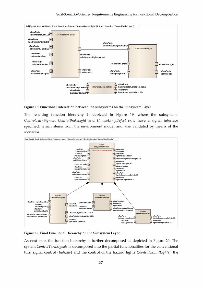
Goal-Scenario-Oriented Requirements Engineering for Functional Decomposition
37
Figure 18: Functional Interaction between the subsystems on the Subsystem Layer
The resulting function hierarchy is depicted in Figure 19, where the subsystems
ControlTurnSignals, ControlBrakeLight and HandleLampDefect now have a signal interface
specified, which stems from the environment model and was validated by means of the
scenarios.
Figure 19: Final Functional Hierarchy on the Subsystem Layer
As next step, the function hierarchy is further decomposed as depicted in Figure 20. The
system ControlTurnSignals is decomposed into the partial functionalities for the conventional
turn signal control (Indicate) and the control of the hazard lights (SwitchHazardLights), the
ibd [SysML Internal Block] 2.1.3. Functions / States "ControlBrakeLight" [2.1.3.2. Function "ControlBrakeLight"]
«flowPort» brake
«flowPort»
emergencyBrake
«flowPort» light
«flowPort»
l ightIntense
«flowPort»
switchHazardLightsInternal
: ControlBrakeLight
«flowPort» brake
«flowPort»
emergencyBrake
«flowPort» light
«flowPort»
l ightIntense
«flowPort»
switchHazardLightsInternal
«flowPort»
indicateLeftReq
«flowPort»
indicateRightReq
«flowPort»
switchHazardLights
«flowPort»
indicateAct
«flowPort»
l ightIndicateLeftLED
«flowPort»
l ightIndicateRightLED
«flowPort»
l ightHazardLightsLED
«flowPort»
switchHazardLightsInternal
: ControlTurnSignals
«flowPort»
indicateLeftReq
«flowPort»
indicateRightReq
«flowPort»
switchHazardLights
«flowPort»
indicateAct
«flowPort»
l ightIndicateLeftLED
«flowPort»
l ightIndicateRightLED
«flowPort»
l ightHazardLightsLED
«flowPort»
switchHazardLightsInternal
«flowPort»
indicatorLampDefect
«flowPort»
brakeLightDefect
«flowPort»
l ightIndicatorLampDefectLED
«flowPort»
l ightBrakeLightDefectLED
: HandleLampDefect«flowPort»
indicatorLampDefect
«flowPort»
brakeLightDefect
«flowPort»
l ightIndicatorLampDefectLED
«flowPort»
l ightBrakeLightDefectLED
bdd [SysML Block Definition] 2.2.3. Functions / States "ControlTurnSignals" [2.2.3.1. Function "ControlTurnSignals"]
«flowPort»
indicateLeftReq
«flowPort»
indicateRightReq
«flowPort»
switchHazardLights
«flowPort» brake
«flowPort»
emergencyBrake
«flowPort»
indicateAct
«flowPort» light
«flowPort»
l ightIntense
«flowPort»
l ightIndicateLeftLED
«flowPort» lightIndicateRightLED
«flowPort»
l ightHazardLightsLED
«flowPort»
l ightIndicatorLampDefectLED
«flowPort»
l ightBrakeLightDefectLED
«flowPort»
indicatorLampDefect
«flowPort»
brakeLightDefect
«block»
BodyControlModule
- switchHazardLightsInternal«flowPort»
indicateLeftReq
«flowPort»
indicateRightReq
«flowPort»
switchHazardLights
«flowPort» brake
«flowPort»
emergencyBrake
«flowPort»
indicateAct
«flowPort» light
«flowPort»
l ightIntense
«flowPort»
l ightIndicateLeftLED
«flowPort» lightIndicateRightLED
«flowPort»
l ightHazardLightsLED
«flowPort»
l ightIndicatorLampDefectLED
«flowPort»
l ightBrakeLightDefectLED
«flowPort»
indicatorLampDefect
«flowPort»
brakeLightDefect
«flowPort» indicateLeftReq
«flowPort»
indicateRightReq
«flowPort»
switchHazardLights
«flowPort»
indicateAct
«flowPort» lightIndicateLeftLED
«flowPort» lightIndicateRightLED
«flowPort»
l ightHazardLightsLED
«flowPort» «systemSignal»
switchHazardLightsInternal
«block»
ControlTurnSignals
«flowPort» indicateLeftReq
«flowPort»
indicateRightReq
«flowPort»
switchHazardLights
«flowPort»
indicateAct
«flowPort» lightIndicateLeftLED
«flowPort» lightIndicateRightLED
«flowPort»
l ightHazardLightsLED
«flowPort» «systemSignal»
switchHazardLightsInternal
«flowPort» brake
«flowPort» «systemSignal»
switchHazardLightsInternal
«flowPort»
emergencyBrake
«flowPort» light
«flowPort»
l ightIntense
«block»
ControlBrakeLight
«flowPort» brake
«flowPort» «systemSignal»
switchHazardLightsInternal
«flowPort»
emergencyBrake
«flowPort» light
«flowPort»
l ightIntense
«flowPort»
indicatorLampDefect
«flowPort»
brakeLightDefect
«flowPort»
l ightIndicatorLampDefectLED
«flowPort»
l ightBrakeLightDefectLED
«block»
HandleLampDefect
«flowPort»
indicatorLampDefect
«flowPort»
brakeLightDefect
«flowPort»
l ightIndicatorLampDefectLED
«flowPort»
l ightBrakeLightDefectLED

Case Study: Automotive Body Control Module
38
system ControlBrakeLights is decomposed into the control of the conventional brake lights as
well as the signalization of an emergency brake, and the system HandleLampDefect is
partitioned into the handling of turn signal (HandleIndicatorDefect) and brake light lamp
defects (HandleBrakeLightDefect). This state of the function hierarchy again serves as input for
the next abstraction layer.
Note, that these subsystems are atomic functions that are not further decomposed, but this
will be decided not until the corresponding decomposition step on the next abstraction layer
(cf. Section 6.3.4). Nevertheless, we will speak in the following of functions to avoid
confusion.
6.2.5 Solution-oriented Requirements
In this case study, solution-oriented requirements are only added on the function layer.
6.2.6 Requirement Pattern Representation of Function Hierarchy on Subsystem Layer
Before the functionality of the subsystem layer is decomposed in the next layer of
abstraction, a switch to the natural-language-based requirement specification could be
performed. The resulting requirement pattern instances are listed below (faded text stems
from the complete system layer, cf. Section 6.1.6).
The system BodyControlModule processes the following signals: indicateLeftReq,
indicateRightReq, switchHazardLights, brake, emergencyBrake, indicatorLampDefect,
brakeLightDefect.
The system BodyControlModule creates the following signals: indicateAct,
lightIndicateLeftLED, lightIndicateRightLED, lightHazardLightsLED, light, lightIntense,
switchHazardLights, lightIndicatorLampDefectLED, lightBrakeLightDefectLED.
The system BodyControlModule consists of the following subsystems:
ControlTurnSignals, ControlBrakeLight, HandleLampDefect.
The system ControlTurnSignals processes the following signals: indicateLeftReq,
indicateRightReq, switchHazardLights.
The system ControlTurnSignals creates the following signals: indicateAct,
lightIndicateLeftLED, lightIndicateRightLED, lightHazardLightsLED.
The system ControlBrakeLight processes the following signals: brake, emergencyBrake.
The system ControlBrakeLight creates the following signals: light, lightIntense,
switchHazardLights.
The system HandleLampDefect processes the following signals: indicatorLampDefect,
brakeLightDefect.
The system HandleLampDefect creates the following signals:
lightIndicatorLampDefectLED, lightBrakeLightDefectLED.
The functionality of the system ControlTurnSignals consists of the following functions:
Indicate, SwitchHazardLights.
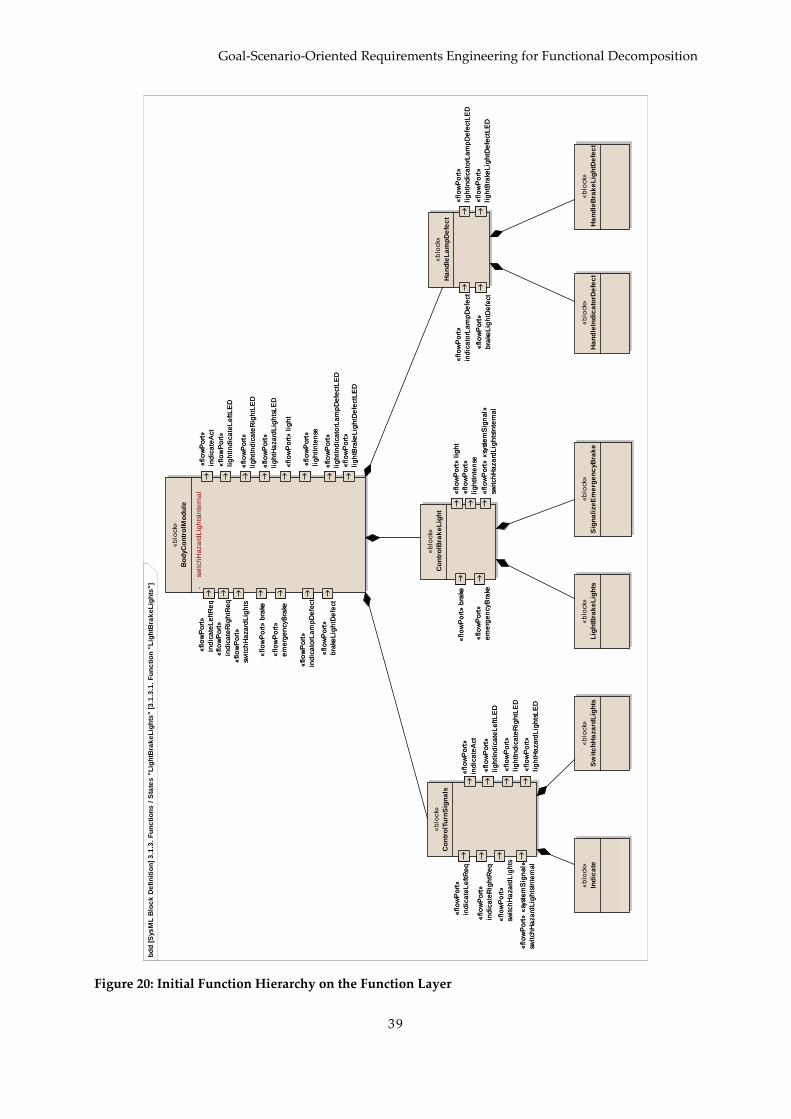
Goal-Scenario-Oriented Requirements Engineering for Functional Decomposition
39
Figure 20: Initial Function Hierarchy on the Function Layer
bd
d [
Sys
ML
Blo
ck
De
fin
itio
n]
3.1
.3.
Fu
nc
tio
ns
/ S
tate
s "
Lig
htB
rak
eL
igh
ts" [
3.1
.3.1
. F
un
cti
on
"L
igh
tBra
ke
Lig
hts
"]
«fl
ow
Po
rt»
ind
ica
teL
eft
Re
q
«fl
ow
Po
rt»
ind
ica
teR
igh
tRe
q
«fl
ow
Po
rt»
swit
ch
Ha
za
rdL
igh
ts
«fl
ow
Po
rt»
bra
ke
«fl
ow
Po
rt»
em
erg
en
cyB
rake
«fl
ow
Po
rt»
ind
ica
teA
ct
«fl
ow
Po
rt»
lig
ht
«fl
ow
Po
rt»
lig
htI
nte
nse
«fl
ow
Po
rt»
lig
htI
nd
ica
teL
eft
LE
D
«fl
ow
Po
rt»
lig
htI
nd
ica
teR
igh
tLE
D
«fl
ow
Po
rt»
lig
htH
aza
rdL
igh
tsL
ED
«fl
ow
Po
rt»
ind
ica
torL
am
pD
efe
ct
«fl
ow
Po
rt»
bra
keL
igh
tDe
fect
«fl
ow
Po
rt»
lig
htI
nd
ica
torL
am
pD
efe
ctL
ED
«fl
ow
Po
rt»
lig
htB
rake
Lig
htD
efe
ctL
ED
«b
lock»
Bo
dyC
on
tro
lMo
du
le
- sw
itch
Ha
za
rdL
igh
tsIn
tern
al
«fl
ow
Po
rt»
ind
ica
teL
eft
Re
q
«fl
ow
Po
rt»
ind
ica
teR
igh
tRe
q
«fl
ow
Po
rt»
swit
ch
Ha
za
rdL
igh
ts
«fl
ow
Po
rt»
bra
ke
«fl
ow
Po
rt»
em
erg
en
cyB
rake
«fl
ow
Po
rt»
ind
ica
teA
ct
«fl
ow
Po
rt»
lig
ht
«fl
ow
Po
rt»
lig
htI
nte
nse
«fl
ow
Po
rt»
lig
htI
nd
ica
teL
eft
LE
D
«fl
ow
Po
rt»
lig
htI
nd
ica
teR
igh
tLE
D
«fl
ow
Po
rt»
lig
htH
aza
rdL
igh
tsL
ED
«fl
ow
Po
rt»
ind
ica
torL
am
pD
efe
ct
«fl
ow
Po
rt»
bra
keL
igh
tDe
fect
«fl
ow
Po
rt»
lig
htI
nd
ica
torL
am
pD
efe
ctL
ED
«fl
ow
Po
rt»
lig
htB
rake
Lig
htD
efe
ctL
ED
«fl
ow
Po
rt»
ind
ica
teL
eft
Re
q
«fl
ow
Po
rt»
ind
ica
teR
igh
tRe
q
«fl
ow
Po
rt»
swit
ch
Ha
za
rdL
igh
ts
«fl
ow
Po
rt»
ind
ica
teA
ct
«fl
ow
Po
rt»
lig
htI
nd
ica
teL
eft
LE
D
«fl
ow
Po
rt»
lig
htI
nd
ica
teR
igh
tLE
D
«fl
ow
Po
rt»
lig
htH
aza
rdL
igh
tsL
ED
«fl
ow
Po
rt»
«sy
ste
mS
ign
al»
swit
ch
Ha
za
rdL
igh
tsIn
tern
al
«b
lock»
Co
ntr
olT
urn
Sig
na
ls
«fl
ow
Po
rt»
ind
ica
teL
eft
Re
q
«fl
ow
Po
rt»
ind
ica
teR
igh
tRe
q
«fl
ow
Po
rt»
swit
ch
Ha
za
rdL
igh
ts
«fl
ow
Po
rt»
ind
ica
teA
ct
«fl
ow
Po
rt»
lig
htI
nd
ica
teL
eft
LE
D
«fl
ow
Po
rt»
lig
htI
nd
ica
teR
igh
tLE
D
«fl
ow
Po
rt»
lig
htH
aza
rdL
igh
tsL
ED
«fl
ow
Po
rt»
«sy
ste
mS
ign
al»
swit
ch
Ha
za
rdL
igh
tsIn
tern
al
«fl
ow
Po
rt»
bra
ke
«fl
ow
Po
rt»
em
erg
en
cyB
rake
«fl
ow
Po
rt»
lig
ht
«fl
ow
Po
rt»
lig
htI
nte
nse
«fl
ow
Po
rt»
«sy
ste
mS
ign
al»
swit
ch
Ha
za
rdL
igh
tsIn
tern
al
«b
lock»
Co
ntr
olB
rak
eL
igh
t
«fl
ow
Po
rt»
bra
ke
«fl
ow
Po
rt»
em
erg
en
cyB
rake
«fl
ow
Po
rt»
lig
ht
«fl
ow
Po
rt»
lig
htI
nte
nse
«fl
ow
Po
rt»
«sy
ste
mS
ign
al»
swit
ch
Ha
za
rdL
igh
tsIn
tern
al
«b
lock»
Ind
ica
te
«b
lock»
Sw
itc
hH
aza
rdL
igh
ts
«b
lock»
Lig
htB
rak
eL
igh
ts
«b
lock»
Sig
na
lize
Em
erg
en
cyB
rak
e
«fl
ow
Po
rt»
bra
keL
igh
tDe
fect
«fl
ow
Po
rt»
ind
ica
torL
am
pD
efe
ct
«fl
ow
Po
rt»
lig
htB
rake
Lig
htD
efe
ctL
ED
«fl
ow
Po
rt»
lig
htI
nd
ica
torL
am
pD
efe
ctL
ED
«b
lock»
Ha
nd
leL
am
pD
efe
ct
«fl
ow
Po
rt»
bra
keL
igh
tDe
fect
«fl
ow
Po
rt»
ind
ica
torL
am
pD
efe
ct
«fl
ow
Po
rt»
lig
htB
rake
Lig
htD
efe
ctL
ED
«fl
ow
Po
rt»
lig
htI
nd
ica
torL
am
pD
efe
ctL
ED
«b
lock»
Ha
nd
leIn
dic
ato
rDe
fec
t
«b
lock»
Ha
nd
leB
rak
eL
igh
tDe
fec
t
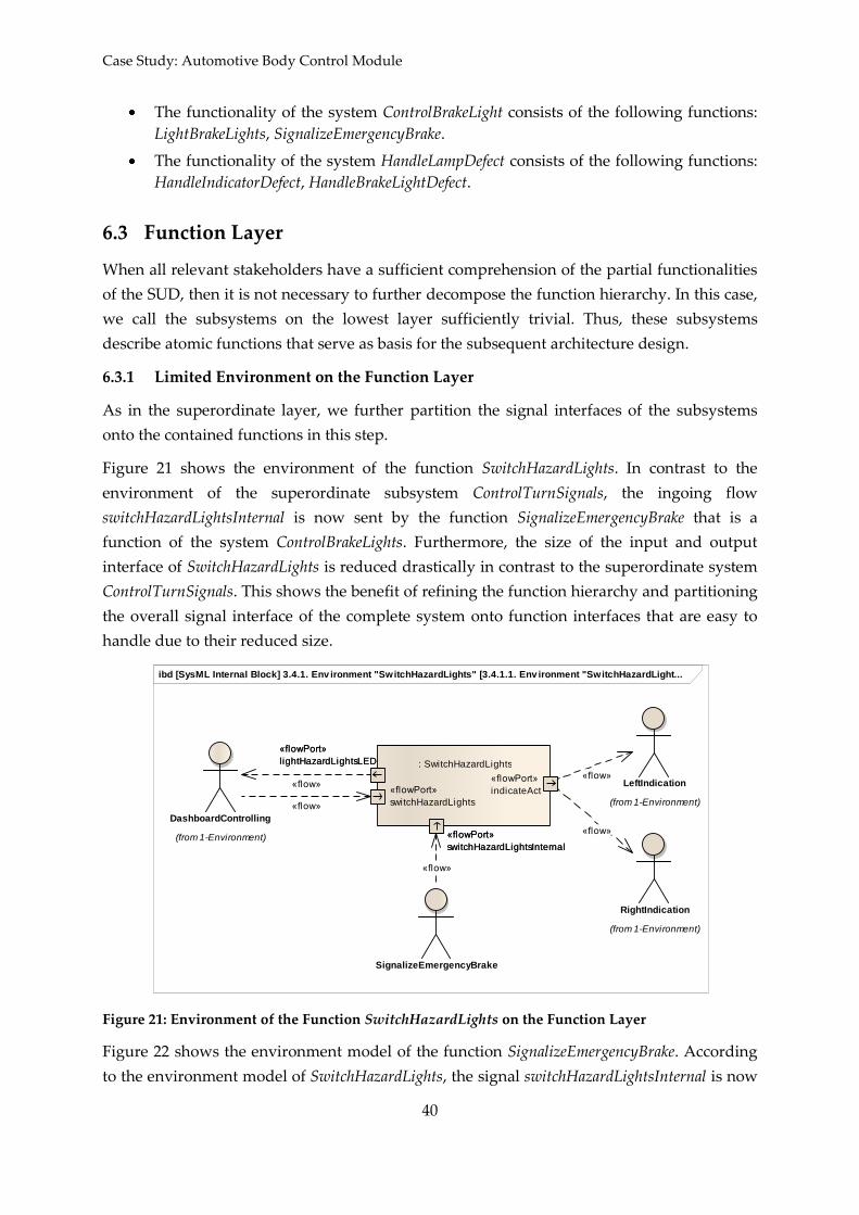
Case Study: Automotive Body Control Module
40
The functionality of the system ControlBrakeLight consists of the following functions:
LightBrakeLights, SignalizeEmergencyBrake.
The functionality of the system HandleLampDefect consists of the following functions:
HandleIndicatorDefect, HandleBrakeLightDefect.
6.3 Function Layer
When all relevant stakeholders have a sufficient comprehension of the partial functionalities
of the SUD, then it is not necessary to further decompose the function hierarchy. In this case,
we call the subsystems on the lowest layer sufficiently trivial. Thus, these subsystems
describe atomic functions that serve as basis for the subsequent architecture design.
6.3.1 Limited Environment on the Function Layer
As in the superordinate layer, we further partition the signal interfaces of the subsystems
onto the contained functions in this step.
Figure 21 shows the environment of the function SwitchHazardLights. In contrast to the
environment of the superordinate subsystem ControlTurnSignals, the ingoing flow
switchHazardLightsInternal is now sent by the function SignalizeEmergencyBrake that is a
function of the system ControlBrakeLights. Furthermore, the size of the input and output
interface of SwitchHazardLights is reduced drastically in contrast to the superordinate system
ControlTurnSignals. This shows the benefit of refining the function hierarchy and partitioning
the overall signal interface of the complete system onto function interfaces that are easy to
handle due to their reduced size.
Figure 21: Environment of the Function SwitchHazardLights on the Function Layer
Figure 22 shows the environment model of the function SignalizeEmergencyBrake. According
to the environment model of SwitchHazardLights, the signal switchHazardLightsInternal is now
ibd [SysML Internal Block] 3.4.1. Env ironment "SwitchHazardLights" [3.4.1.1. Env ironment "SwitchHazardLight...
«flowPort»
indicateAct«flowPort»
switchHazardLights
«flowPort»
l ightHazardLightsLED
«flowPort»
switchHazardLightsInternal
: SwitchHazardLights
«flowPort»
indicateAct«flowPort»
switchHazardLights
«flowPort»
l ightHazardLightsLED
«flowPort»
switchHazardLightsInternal
DashboardControlling
(from 1-Environment)
SignalizeEmergencyBrake
LeftIndication
(from 1-Environment)
RightIndication
(from 1-Environment)
«flow»
«flow»
«flow»
«flow»
«flow»

Goal-Scenario-Oriented Requirements Engineering for Functional Decomposition
41
sent to this function instead of its superordinate system. Apart from that, the interface size
was reduced for this function, as well.
Figure 22: Environment of the Function SignalizeEmergencyBrake on the Function Layer
The other environment models are specified accordingly.
6.3.2 Refined Goals on the Function Layer
In this example, the goals from the complete system layer are not refined any further.
6.3.3 Refined Scenarios on the Function Layer
Figure 23 depicts the scenario Emergency brake light controlling on function layer. It is the
refinement of the scenario on subsystem layer (cf. Section 6.2.3): The subsystem lifelines
ControlBrakeLight and ControlIndicators were decomposed into the atomic functions
SignalizeEmergencyBrake and SwitchHazardLights.
Figure 23: Scenario Emergency brake light controlling on Function Layer
ibd [SysML Internal Block] 3.2.1. Env ironment "SignalizeEmergencyBrake" [3.2.1.1. Env ironment "SignalizeEmergen...
«flowPort»
emergencyBrake
«flowPort»
l ightIntense
«flowPort»
switchHazardLightsInternal
: SignalizeEmergencyBrake«flowPort»
emergencyBrake
«flowPort»
l ightIntense
«flowPort»
switchHazardLightsInternal
BrakeLightSwitching
(from 1-Environment)
BrakePedalLev elSensing
(from 1-Environment)
SwitchHazardLights
«flow»
«flow»
«flow»
sd [Sequence] 3.2.2. Goals / Requirements / Scenarios "SignalizeEmergencyBrake" [3.2.2.1. Scenario "Emergency brake light controlling"]
:BrakePedalLevelSensing
: SignalizeEmergencyBrake
(from 2-Environment)
:BrakeLightSwitching
: SwitchHazardLights
(from 2-Environment)
:DashboardControll ing:LeftIndication :RightIndication
par
emergencyBrake()
lightIntense()
switchHazardLightsInternal()
indicateAct()
indicateAct()
lightHazardLightsLED()

Case Study: Automotive Body Control Module
42
6.3.4 Function Hierarchy on the Function Layer
As a result from the initial function hierarchy for this layer (cf. Figure 20) and the partition of
the signal interfaces in the subsequent step of limiting the environment (cf. Section 6.3.1),
Figure 24 shows the final function hierarchy. Since the partial functionalities on this layer are
sufficiently trivial for all stakeholders and their interfaces are easy to handle, we decompose
them not any further and consider them as atomic functions. These functions have to be
fulfilled by components of the architecture to be designed in the subsequent development
process.
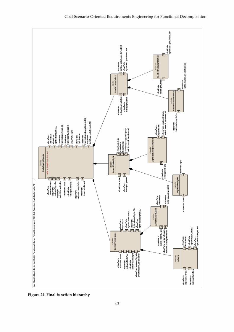
Goal-Scenario-Oriented Requirements Engineering for Functional Decomposition
43
Figure 24: Final function hierarchy
bd
d [
Sys
ML
Blo
ck
De
fin
itio
n]
3.1
.3.
Fu
nc
tio
ns
/ S
tate
s "
Lig
htB
rak
eL
igh
ts" [
3.1
.3.1
. F
un
cti
on
"L
igh
tBra
ke
Lig
hts
"]
«fl
ow
Po
rt»
ind
ica
teL
eft
Re
q
«fl
ow
Po
rt»
ind
ica
teR
igh
tRe
q
«fl
ow
Po
rt»
swit
ch
Ha
za
rdL
igh
ts
«fl
ow
Po
rt»
bra
ke
«fl
ow
Po
rt»
em
erg
en
cyB
rake
«fl
ow
Po
rt»
ind
ica
teA
ct
«fl
ow
Po
rt»
lig
ht
«fl
ow
Po
rt»
lig
htI
nte
nse
«fl
ow
Po
rt»
lig
htI
nd
ica
teL
eft
LE
D
«fl
ow
Po
rt»
lig
htI
nd
ica
teR
igh
tLE
D
«fl
ow
Po
rt»
lig
htH
aza
rdL
igh
tsL
ED
«fl
ow
Po
rt»
ind
ica
torL
am
pD
efe
ct
«fl
ow
Po
rt»
bra
keL
igh
tDe
fect
«fl
ow
Po
rt»
lig
htI
nd
ica
torL
am
pD
efe
ctL
ED
«fl
ow
Po
rt»
lig
htB
rake
Lig
htD
efe
ctL
ED
«b
lock»
Bo
dyC
on
tro
lMo
du
le
- sw
itch
Ha
za
rdL
igh
tsIn
tern
al
«fl
ow
Po
rt»
ind
ica
teL
eft
Re
q
«fl
ow
Po
rt»
ind
ica
teR
igh
tRe
q
«fl
ow
Po
rt»
swit
ch
Ha
za
rdL
igh
ts
«fl
ow
Po
rt»
bra
ke
«fl
ow
Po
rt»
em
erg
en
cyB
rake
«fl
ow
Po
rt»
ind
ica
teA
ct
«fl
ow
Po
rt»
lig
ht
«fl
ow
Po
rt»
lig
htI
nte
nse
«fl
ow
Po
rt»
lig
htI
nd
ica
teL
eft
LE
D
«fl
ow
Po
rt»
lig
htI
nd
ica
teR
igh
tLE
D
«fl
ow
Po
rt»
lig
htH
aza
rdL
igh
tsL
ED
«fl
ow
Po
rt»
ind
ica
torL
am
pD
efe
ct
«fl
ow
Po
rt»
bra
keL
igh
tDe
fect
«fl
ow
Po
rt»
lig
htI
nd
ica
torL
am
pD
efe
ctL
ED
«fl
ow
Po
rt»
lig
htB
rake
Lig
htD
efe
ctL
ED
«fl
ow
Po
rt»
ind
ica
teL
eft
Re
q
«fl
ow
Po
rt»
ind
ica
teR
igh
tRe
q
«fl
ow
Po
rt»
swit
ch
Ha
za
rdL
igh
ts
«fl
ow
Po
rt»
ind
ica
teA
ct
«fl
ow
Po
rt»
lig
htI
nd
ica
teL
eft
LE
D
«fl
ow
Po
rt»
lig
htI
nd
ica
teR
igh
tLE
D
«fl
ow
Po
rt»
lig
htH
aza
rdL
igh
tsL
ED
«fl
ow
Po
rt»
«sy
ste
mS
ign
al»
swit
ch
Ha
za
rdL
igh
tsIn
tern
al
«b
lock»
Co
ntr
olT
urn
Sig
na
ls
«fl
ow
Po
rt»
ind
ica
teL
eft
Re
q
«fl
ow
Po
rt»
ind
ica
teR
igh
tRe
q
«fl
ow
Po
rt»
swit
ch
Ha
za
rdL
igh
ts
«fl
ow
Po
rt»
ind
ica
teA
ct
«fl
ow
Po
rt»
lig
htI
nd
ica
teL
eft
LE
D
«fl
ow
Po
rt»
lig
htI
nd
ica
teR
igh
tLE
D
«fl
ow
Po
rt»
lig
htH
aza
rdL
igh
tsL
ED
«fl
ow
Po
rt»
«sy
ste
mS
ign
al»
swit
ch
Ha
za
rdL
igh
tsIn
tern
al
«fl
ow
Po
rt»
bra
ke
«fl
ow
Po
rt»
em
erg
en
cyB
rake
«fl
ow
Po
rt»
lig
ht
«fl
ow
Po
rt»
lig
htI
nte
nse
«fl
ow
Po
rt»
«sy
ste
mS
ign
al»
swit
ch
Ha
za
rdL
igh
tsIn
tern
al
«b
lock»
Co
ntr
olB
rak
eL
igh
t
«fl
ow
Po
rt»
bra
ke
«fl
ow
Po
rt»
em
erg
en
cyB
rake
«fl
ow
Po
rt»
lig
ht
«fl
ow
Po
rt»
lig
htI
nte
nse
«fl
ow
Po
rt»
«sy
ste
mS
ign
al»
swit
ch
Ha
za
rdL
igh
tsIn
tern
al
«fl
ow
Po
rt»
ind
ica
teL
eft
Re
q
«fl
ow
Po
rt»
ind
ica
teR
igh
tRe
q
«fl
ow
Po
rt»
ind
ica
teA
ct
«fl
ow
Po
rt»
lig
htI
nd
ica
teL
eft
LE
D
«fl
ow
Po
rt»
lig
htI
nd
ica
teR
igh
tLE
D
«b
lock»
Ind
ica
te
«fl
ow
Po
rt»
ind
ica
teL
eft
Re
q
«fl
ow
Po
rt»
ind
ica
teR
igh
tRe
q
«fl
ow
Po
rt»
ind
ica
teA
ct
«fl
ow
Po
rt»
lig
htI
nd
ica
teL
eft
LE
D
«fl
ow
Po
rt»
lig
htI
nd
ica
teR
igh
tLE
D
«fl
ow
Po
rt»
swit
ch
Ha
za
rdL
igh
ts
«fl
ow
Po
rt»
ind
ica
teA
ct
«fl
ow
Po
rt»
lig
htH
aza
rdL
igh
tsL
ED
«fl
ow
Po
rt»
«sy
ste
mS
ign
al»
swit
ch
Ha
za
rdL
igh
tsIn
tern
al
«b
lock»
Sw
itc
hH
aza
rdL
igh
ts
«fl
ow
Po
rt»
swit
ch
Ha
za
rdL
igh
ts
«fl
ow
Po
rt»
ind
ica
teA
ct
«fl
ow
Po
rt»
lig
htH
aza
rdL
igh
tsL
ED
«fl
ow
Po
rt»
«sy
ste
mS
ign
al»
swit
ch
Ha
za
rdL
igh
tsIn
tern
al
«fl
ow
Po
rt»
bra
ke
«fl
ow
Po
rt»
lig
ht
«b
lock»
Lig
htB
rak
eL
igh
ts
«fl
ow
Po
rt»
bra
ke
«fl
ow
Po
rt»
lig
ht
«fl
ow
Po
rt»
em
erg
en
cyB
rake
«fl
ow
Po
rt»
lig
htI
nte
nse
«fl
ow
Po
rt»
«sy
ste
mS
ign
al»
swit
ch
Ha
za
rdL
igh
tsIn
tern
al
«b
lock»
Sig
na
lize
Em
erg
en
cyB
rak
e
«fl
ow
Po
rt»
em
erg
en
cyB
rake
«fl
ow
Po
rt»
lig
htI
nte
nse
«fl
ow
Po
rt»
«sy
ste
mS
ign
al»
swit
ch
Ha
za
rdL
igh
tsIn
tern
al«
flo
wP
ort
»
bra
keL
igh
tDe
fect
«fl
ow
Po
rt»
ind
ica
torL
am
pD
efe
ct
«fl
ow
Po
rt»
lig
htB
rake
Lig
htD
efe
ctL
ED
«fl
ow
Po
rt»
lig
htI
nd
ica
torL
am
pD
efe
ctL
ED
«b
lock»
Ha
nd
leL
am
pD
efe
ct
«fl
ow
Po
rt»
bra
keL
igh
tDe
fect
«fl
ow
Po
rt»
ind
ica
torL
am
pD
efe
ct
«fl
ow
Po
rt»
lig
htB
rake
Lig
htD
efe
ctL
ED
«fl
ow
Po
rt»
lig
htI
nd
ica
torL
am
pD
efe
ctL
ED
«fl
ow
Po
rt»
ind
ica
torL
am
pD
efe
ct
«fl
ow
Po
rt»
lig
htI
nd
ica
torL
am
pD
efe
ctL
ED
«b
lock»
Ha
nd
leIn
dic
ato
rDe
fec
t«
flo
wP
ort
»
ind
ica
torL
am
pD
efe
ct
«fl
ow
Po
rt»
lig
htI
nd
ica
torL
am
pD
efe
ctL
ED
«fl
ow
Po
rt»
bra
keL
igh
tDe
fect
«fl
ow
Po
rt»
lig
htB
rake
Lig
htD
efe
ctL
ED
«b
lock»
Ha
nd
leB
rak
eL
igh
tDe
fec
t«
flo
wP
ort
»
bra
keL
igh
tDe
fect
«fl
ow
Po
rt»
lig
htB
rake
Lig
htD
efe
ctL
ED
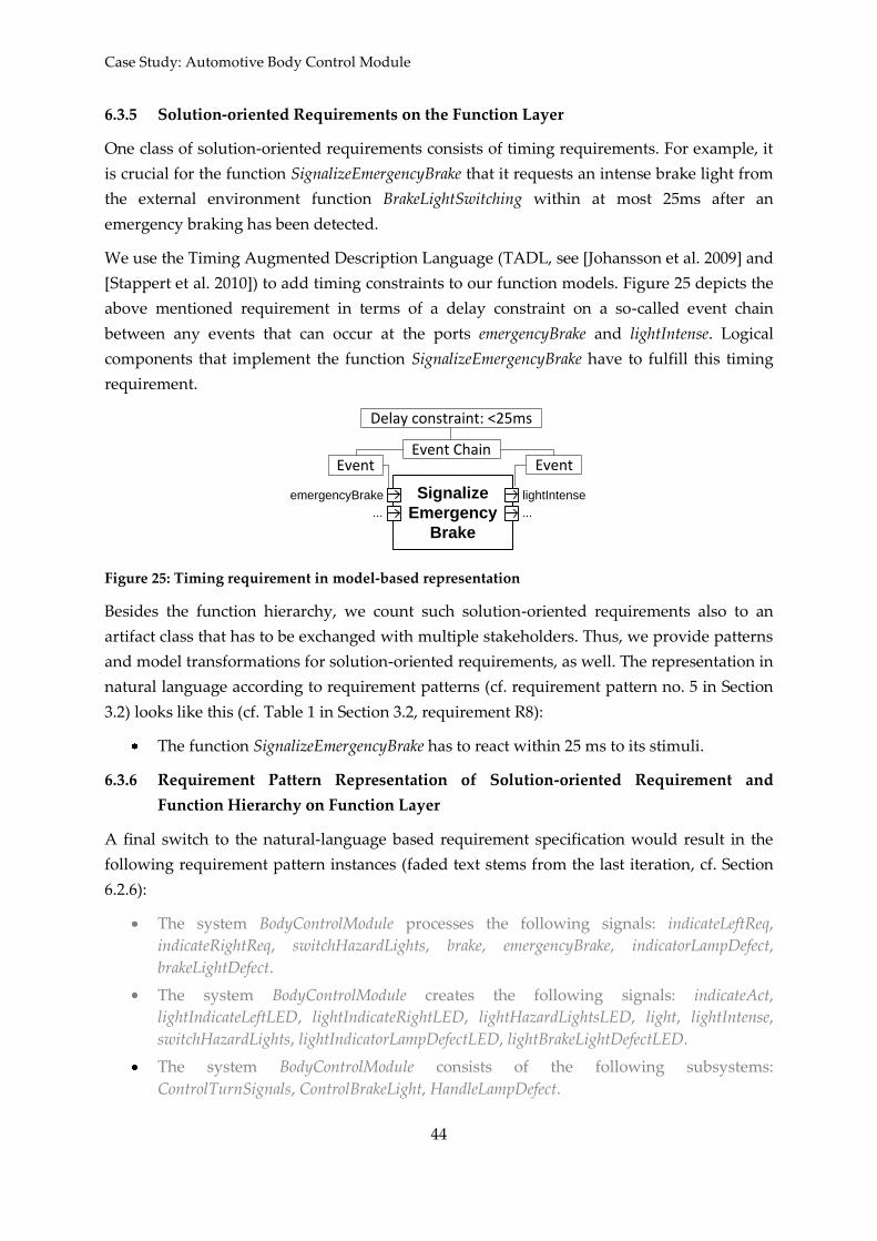
Case Study: Automotive Body Control Module
44
6.3.5 Solution-oriented Requirements on the Function Layer
One class of solution-oriented requirements consists of timing requirements. For example, it
is crucial for the function SignalizeEmergencyBrake that it requests an intense brake light from
the external environment function BrakeLightSwitching within at most 25ms after an
emergency braking has been detected.
We use the Timing Augmented Description Language (TADL, see [Johansson et al. 2009] and
[Stappert et al. 2010]) to add timing constraints to our function models. Figure 25 depicts the
above mentioned requirement in terms of a delay constraint on a so-called event chain
between any events that can occur at the ports emergencyBrake and lightIntense. Logical
components that implement the function SignalizeEmergencyBrake have to fulfill this timing
requirement.
Signalize
Emergency
Brake
emergencyBrake lightIntense
... ...
Event EventEvent Chain
Delay constraint: <25ms
Figure 25: Timing requirement in model-based representation
Besides the function hierarchy, we count such solution-oriented requirements also to an
artifact class that has to be exchanged with multiple stakeholders. Thus, we provide patterns
and model transformations for solution-oriented requirements, as well. The representation in
natural language according to requirement patterns (cf. requirement pattern no. 5 in Section
3.2) looks like this (cf. Table 1 in Section 3.2, requirement R8):
The function SignalizeEmergencyBrake has to react within 25 ms to its stimuli.
6.3.6 Requirement Pattern Representation of Solution-oriented Requirement and
Function Hierarchy on Function Layer
A final switch to the natural-language based requirement specification would result in the
following requirement pattern instances (faded text stems from the last iteration, cf. Section
6.2.6):
The system BodyControlModule processes the following signals: indicateLeftReq,
indicateRightReq, switchHazardLights, brake, emergencyBrake, indicatorLampDefect,
brakeLightDefect.
The system BodyControlModule creates the following signals: indicateAct,
lightIndicateLeftLED, lightIndicateRightLED, lightHazardLightsLED, light, lightIntense,
switchHazardLights, lightIndicatorLampDefectLED, lightBrakeLightDefectLED.
The system BodyControlModule consists of the following subsystems:
ControlTurnSignals, ControlBrakeLight, HandleLampDefect.

Goal-Scenario-Oriented Requirements Engineering for Functional Decomposition
45
The system ControlTurnSignals processes the following signals: indicateLeftReq,
indicateRightReq, switchHazardLights.
The system ControlTurnSignals creates the following signals: indicateAct,
lightIndicateLeftLED, lightIndicateRightLED, lightHazardLightsLED.
The system ControlBrakeLight processes the following signals: brake, emergencyBrake.
The system ControlBrakeLight creates the following signals: light, lightIntense,
switchHazardLights.
The system HandleLampDefect processes the following signals: indicatorLampDefect,
brakeLightDefect.
The system HandleLampDefect creates the following signals:
lightIndicatorLampDefectLED, lightBrakeLightDefectLED.
The functionality of the system ControlTurnSignals consists of the following functions:
Indicate, SwitchHazardLights.
The functionality of the system ControlBrakeLight consists of the following functions:
LightBrakeLights, SignalizeEmergencyBrake.
The functionality of the system HandleLampDefect consists of the following
functions: HandleIndicatorDefect, HandleBrakeLightDefect.
The function SignalizeEmergencyBrake has to react within 25 ms to its stimuli.
The function Indicate processes the following signals: indicateLeftReq, indicateRightReq.
The function Indicate creates the following signals: indicateAct, lightIndicateLeftLED,
lightIndicateRightLED.
The function SwitchHazardLights processes the following signals: switchHazardLights.
The function SwitchHazardLights creates the following signals: indicateAct,
lightHazardLightsLED.
The function LightBrakeLights processes the following signals: brake.
The function LightBrakeLights creates the following signals: light.
The function SignalizeEmergencyBrake processes the following signals: emergencyBrake.
The function SignalizeEmergencyBrake creates the following signals: lightIntense,
switchHazardLights.
The function HandleIndicatorDefect processes the following input signals:
indicatorLampDefect.
The function HandleIndicatorDefect creates the following signals:
lightIndicatorLampDefectLED.
The function HandleBrakeLightDefect processes the following signals: brakeLightDefect.
The function HandleBrakeLightDefect creates the following signals:
lightBrakeLightDefectLED.

Conclusions and Future Work
46
7
Natural language is the most common documentation format for requirements in the
development of today’s embedded systems [Juristo et al. 2002, Pretschner et al. 2007].
However, because of the inherent ambiguity of natural language, the volume of textually
documented requirements in many systems, and the difficulty handling system complexity
and requirements traceability, the use of model-based requirements documentation has been
advocated [Sikora et al. 2012]. Yet, since requirements often build the basis for contractual
agreements between suppliers and OEMs and due to missing methodical guidelines on
when to apply models during system development, models are rarely applied in practice
[Sikora et al. 2011]. We have developed a combined requirements engineering approach
based on controlled natural language [Holtmann et al. 2011b] and the requirements
viewpoint of the SPES Modeling Framework [Daun et al. 2012] in order to combine the
advantages of model-based requirements documentation and natural language-based
requirements documentation. By making use of this combined approach, it is possible to
elicit and document requirements continuously and trace requirements from origin to their
model-based manifestation in a function hierarchy.
We have applied the combined approach to a real-world industrial case study from the
automotive industry, that is, a Body Control Module, which presents a new paradigm in
automotive control unit interaction. The case study showed that the combined approach can
be applied to automotive systems and supports the engineering of requirements consistently
across multiple abstraction layers. It can be seen from the case study how context models
and goal models can be used in early requirements engineering phases and be refined using
scenarios. The resulting function hierarchy can be used in following phases of a model-based
development process as a basis for the conception of the architecture of the SUD.
Furthermore, the textual requirement pattern representation can be used as basis for legal
documents exchanged with the customer or for document-oriented, intermediate reviews.
This work hence does not only provide a benefit for the integrated development using both
model-based and natural language-based requirements specifications, but also shows how
system requirements and a function hierarchy can be co-developed and hence shows how a
transition from the requirements viewpoint to the functional viewpoint of the SPES
Modeling Framework [Vogelsang et al. 2012] can be performed. However, given that this
transition is not complete (cf. [Daun et al. 2012, Vogelsang et al. 2012]), future work will
address how the transition between these viewpoints can be improved, and how with the aid
of model-based requirements and controlled natural language related development
activities, for example, safety engineering, artifact validation, or functional analysis, can be
integrated.
Goal-Scenario-Oriented Requirements Engineering for Functional Decomposition
47
[Ambiola and Gervasi 1997] V. Ambriola, V. Gervasi: Processing Natural Language
Requirements. In: Proceedings of the 12th IEEE
International Conference on Automated Software
Engineering, 1997.
[Ambiola and Gervasi 2006] V. Ambriola, V. Gervasi: On the Systematic Analysis of
Natural Language Requirements with CIRCE. In:
Proceedings of the International Conference on
Automated Software Engineering, 2006.
[AutomotiveSIG 2010] Automotive Special Interest Group (SIG): Automotive
SPICE. Process Reference Model.
http://www.automotivespice.com/automotiveSIG_PRM_
v45.pdf. Accessed on: June 7th, 2012.
[Balzert 2009] H. Balzert: Lehrbuch der Softwaretechnik: Basiskonzepte
und Requirements Engineering, 3rd Edition, Spektrum
Akademischer Verlag, Heidelberg, 2003.
[Braun et al. 2010] P. Braun, M. Broy, F. Houdek, M. Kirchmayr, M. Müller,
B. Penzenstadler, K. Pohl, T. Weyer: Guiding
requirements engineering for software-intensive
embedded systems in the automotive industry.
Computer Science Research and Development, Springer,
Heidelberg, 2010, DOI: 10.1007/s00450-010-0136-y
[Bühne et al. 2004] S. Bühne, G. Halmans, K. Pohl, M. Weber, H.
Kleinwechter, T. Wierczoch: Defining requirements at
different levels of abstraction. In: Proceedings of the 12th
IEEE International Requirements Engineering
Conference, 2004.
[Daun et al. 2012] M. Daun, B. Tenbergen, T. Weyer: Requirements
Viewpoint. In: K. Pohl, H. Hönninger, R. Achatz, M.
Broy: Model-Based Engineering of Embedded Systems –
The SPES 2020 Methodology. Springer, 2012.
[Davis 1993] A. M. Davis: Software Requirements – Objects,
Functions, States. 2nd Edition, Prentice Hall, Englewood
Cliffs, New Jersey, 1993.
[Davis 2005] A. Davis: Just Enough Requirements Engineering: Where
Software Development Meets Marketing. Dorset House
Publishing, New York, 2005.

Conclusions and Future Work
48
[Deeptimahanti and Barbar 2009] D. K. Deeptimahanti, M. A. Babar: An Automated Tool
for Generating UML Models from Natural Language
Requirements. In: Proceedings of the 24th IEEE/ACM
International Conference on Automated Software
Engineering, 2009.
[Deeptimahanti and Sanyal 2011] D. K. Deeptimahanti, R. Sanyal: Semi-Automatic
Generation of UML Models from Natural Language
Requirements. In: Proceedings of the 4th India Software
Engineering Conference, 2011.
[DeMarco 1979] T. DeMarco: Structured Analysis and System
Specification. Yourdon Press, Upper Saddle River, New
Jersey, 1979.
[Drusinsky 2008] D. Drusinsky: From UML Activity Diagrams to
Specification Requirements. In: IEEE International
Conference on System of Systems Engineering, 2008.
[Fine 2002] K. Fine: The Limits of Abstraction. Oxford University
Press, New York, 2002.
[Flynn and Warhurst 1994] D. J. Flynn, R. Warhurst: An empirical study of the
validation process within requirements determination.
Information Systems Journal 4, 1994, pp. 185-212.
[Fockel et al. 2012a] M. Fockel, J. Holtmann, J. Meyer: Semi-automatic
Establishment and Maintenance of Valid Traceability in
Automotive Development Processes. In: Proceedings of
the 2nd International Workshop on Software Engineering
for Embedded Systems, 2012.
[Fockel et al. 2012b] M. Fockel, P. Heidl, J. Höfflinger, H. Hönninger, J.
Holtmann, W. Horn, J. Meyer, M. Meyer, J. Schäuffele:
Application and Evaluation in the Automotive Domain.
In: K. Pohl, H. Hönninger, R. Achatz, M. Broy: Model-
Based Engineering of Embedded Systems – The SPES
2020 Methodology. Springer, 2012.
[Gausemeier et al. 2009] J. Gausemeier; U. Frank; J. Donoth; S. Kahl: Specification
technique for the description of self-optimizing
mechatronic systems. Research in Engineering Design 20,
2009, pp. 201–223.
[Goldsmith 2004] R. Goldsmith: Discovering Real Business Requirements
for Software Project Success. Artech House, Boston, 2004.
Goal-Scenario-Oriented Requirements Engineering for Functional Decomposition
49
[Gotel and Finkelstein 1994] O. C. Z. Gotel, C. W. Finkelstein: An analysis of the
requirements traceability problem. In: Proceedings of the
1st International Conference on Requirements
Engineering, 1994.
[Harmain and Gaizauskas 2000] H. M. Harmain, R. Gaizauskas: CM-Builder: An
Automated NL-based CASE Tool. Proceedings of the 15th
IEEE International Conference on Automated Software
Engineering, 2000.
[Harmain and Gaizauskas 2003] H. M. Harmain, R. Gaizauskas: CM-Builder: A Natural
Language-Based CASE Tool for Object-Oriented
Analysis. In: Automated Software Engineering 10(2),
2003, pp. 157–181
[Holtmann 2010] J. Holtmann. Mit Satzmustern von textuellen
Anforderungen zu Modellen. In: OBJEKTspektrum
RE/2010. (Online Themenspecial Requirements
Engineering) http://www.sigs-
datcom.de/fileadmin/user_upload/zeitschriften/os/2010/
RE/holtmann_OS_RE_2010.pdf. Accessed on: June 7th,
2012.
[Holtmann et al. 2011a] J. Holtmann, J. Meyer, M. Meyer: A Seamless Model-
Based Development Process for Automotive Systems. In:
Workshopband Software Engineering, Lecture Notes in
Informatics Volume 184, Bonner Köllen Verlag, Bonn,
2011.
[Holtmann et al. 2011b] J. Holtmann, J. Meyer, M. von Detten: Automatic
Validation and Correction of Formalized, Textual
Requirements. In: Proceedings of the 4th IEEE
International Conference on Software Testing,
Verification and Validation Workshops, 2011.
[Huijsen 1998a] W.-O. Huijsen: Controlled Language – An Introduction.
In: Proceedings of the 2nd International Workshop on
Controlled Language Applications, 1998..
[Huisen 1998b] W.-O. Huijsen: Completeness of Compositional Trans-
lation, Elinkwijk Drukkerij B.V., 1998.
[IEEE 830] Institute of Electrical and Electronics Engineers: IEEE
Std. 830-1998: IEEE Recommended Practice for Software
Requirements Specifications, 1998.
Conclusions and Future Work
50
[Ilieva and Ormandjieva 2006] M. G. Ilieva, O. Ormandjieva: Models Derived from
Automatically Analyzed Textual User Requirements. In:
Proceedings of the 4th International Conference on
Software Engineering Research, Management and
Applications, 2006.
[ISO 26262] International Organization for Standardization:
ISO26262: Road Vehicles – Functional Safety, 2011.
[Jersak et al. 2003] M. Jersak, K. Richter, R. Ernst, J. Braam, Z. Jiang, F. Wolf:
Formal methods for integration of automotive software.
In: Proceedings of the Design, Automation and Test in
Europe Conference and Exhibition, 2003.
[Johansson et al. 2009] R. Johansson; P. Frey; J. Jonsson; J. Nordlander; R. M.
Pathan; N. Feiertag; M. Schlager; H. Espinoza; K.
Richtter; St. Kuntz; H. Lönn; R. T. Kolagari; H. Blom:
TADL: Timing Augmented Description Language
Version 2. 2009.
[Juristo et al. 2002] N. Juristo, A. Moreno, A. Silva: Is the European industry
moving toward solving RE problems? IEEE Software
19(6), 2002, pp. 70–77.
[Kapeller and Krause 2006] R. Kapeller, S. Krause: So natürlich wie Sprechen -
Embedded Systeme modellieren. In: Design & Elektronik
08, 2006, pp. 64–67.
[Kiyavitskaya and Zannone 2008] N. Kiyavitskaya, N. Zannone: Requirements Model
Generation to Support Requirements Elicitation: The
Secure Tropos Experience. Automated Software
Engineering 15(2), 2008, pp. 149–173.
[Kof 2009] L. Kof: Translation of Textual Specifications to Automata
by Means of Discourse Context Modeling. In: Lecture
Notes in Computure Science 5512, Springer, Heidelberg,
2009, pp. 197–211.
[Kof 2010] L. Kof: From Requirements Documents to System
Models: A Tool for Interactive Semi-Automatic
Translation. In: Proceedings of the 18th IEEE International
Requirements Engineering Conference, 2010.

Goal-Scenario-Oriented Requirements Engineering for Functional Decomposition
51
[Lu et al. 2007] C.-W. Lu, W. C. Chu, C.-H. Chang, C. H. Wang: A
Model-Based Object-Oriented Approach to Requirement
Engineering (MORE). In: Proceedings of the 1st
International Computer Software and Applications
Conference, 2007.
[Lu et al. 2008a] C.-W. Lu, W. C. Chu, C.-H. Chang: Model-Based Object-
Oriented Requirement Engineering and its Support to
Software Documents Integration. In: Proceedings of the
2008 International Conference on Software Engineering
Research and Practice, 2008.
[Lu et al. 2008b] C.-W. Lu, C.-H. Chang, W. C. Chu, Y.-W. Cheng, H.-C.
Chang: A Requirement Tool to Support Model-Based
Requirement Engineering. In: Proceedings of the 2nd
International Computer Software and Applications
Conference, 2008.
[Meziane et al. 2008] F. Meziane, N. Athanasakis, S. Ananiadou: Generating
Natural Language Specifications from UML Class
Diagrams. Requirements Engineering 13(1), 2008, pp. 1-
18.
[Mich et al. 2002] L. Mich, R. Garigliano, A. Zanasi, C. A. Brebbia, N. F. F.
E. Ebecken, P. Melli: NL-OOPS: A Requirements
Analysis Tool Based on Natural Language Processing.
Management Information Systems 6, 2002, pp. 321–330.
[Neill and Laplante 2003] C. Neill, P. Laplante: Requirements Engineering: the state
of Practice. IEEE Software 20(4), 2003, pp. 40-45.
[Nicolás and Toval 2009] J. Nicolás, A. Toval: On the Generation of Requirements
Specifications from Software Engineering Models: A
Systematic Literature Review. Information and Software
Technology 51(9), 2009, pp. 1291-1307..
[Nuseibeh 2001] B. Nuseibeh: Weaving together requirements and
architectures. In: IEEE Computer 34(3), 2001, pp. 115-119.
[OMG 2003] Object Management Group: MDA Guide, Version 1.0.1.
OMG Document Number: omg/2003-06-01, 2003.
[Pohl 2010] K. Pohl: Requirements Engineering: Foundations,
Principles, and Techniques. Springer, Heidelberg, 2010.

Conclusions and Future Work
52
[Pohl and Sikora 2007] K. Pohl, E. Sikora: The Co-Development of System
Requirements and Functional Architecture. In: J.
Krogstie, A. Lothe Opdahl, S. Brinkkemper: Conceptual
Modelling in Information Systems Engineering. Springer,
Heidelberg, 2007.
[Broy et al. 2012] M. Broy, W. Damm, S. Henkler, K. Pohl, A. Vogelsang, T
Weyer: Introduction to the SPES Modeling Framework.
In: K. Pohl, H. Hönninger, R. Achatz, M. Broy: Model-
Based Engineering of Embedded Systems – The SPES
2020 Methodology. Springer, 2012.
[Vogelsang et al. 2012] A. Vogelsang, S. Eder, M. Feilkas, D. Ratiu: Functional
Viewpoint. In: K. Pohl, H. Hönninger, R. Achatz, M.
Broy: Model-Based Engineering of Embedded Systems –
The SPES 2020 Methodology. Springer, 2012.
[Potts 1995] C. Potts: Using schematic scenarios to understand user
needs. In: Proceedings of the 1st Conference on Designing
Interactive Systems: Processes, Practices, Methods, &
Techniques, 1995.
[Pretschner et al. 2007] A. Pretschner, M. Broy, I. Krüger, Th. Stauner: Software
engineering for automotive systems: a roadmap. In:
Proceedings of Future of Software Engineering, 2007.
[Ross and Schoman 1977] D. T. Ross, K. E. Schoman: Structured Analysis for
Requirements Definition. IEEE Transactions on Software
Engineering SE-3(1), 1977, pp. 6 – 15.
[Royce 1970] W. W. Royce: Managing the Development of Large
Software Systems. In: Proceedings of IEEE WESCON,
1970, pp. 1-9.
[Schäuffele and Zurawka 2003] J. Schäuffele, Th. Zurawka: Automtive Software
Engineering – Grundlagen, Prozesse, Methoden und
Werkzeuge. Vieweg, Wiesbaden, 2003.
[Schürr 1995] A. Schürr: Specification of Graph Translators with Triple
Graph Grammars. In: Graph-Theoretic Concepts in
Computer Science. Springer, Heidelberg, 1995.
[Schwitter 2010] R. Schwitter: Controlled natural languages for
knowledge representation. In: Proceedings of the 23rd
International Conference on Computational Linguistics:
Posters, 2010.
[Sikora et al. 2010] E. Sikora, M. Daun, K. Pohl: Supporting the Consistent
Specification of Scenarios across Multiple Abstraction
Levels. In: Proceedings of Requirements Engineering:
Foundation for Software Quality, 2010.
Goal-Scenario-Oriented Requirements Engineering for Functional Decomposition
53
[Sikora et al. 2011] E. Sikora, B. Tenbergen, K. Pohl: Requirements
engineering for embedded systems: An investigation of
industry needs. In: Proceedings of Requirements
Engineering: Foundation for Software Quality, 2011.
[Sikora et al. 2012] E. Sikora, B. Tenbergen, K. Pohl: Industry Needs and
Research Directions in Requirements Engineering for
Embedded Systems. Requirements Engineering 17(1),
2012, pp. 57-78.
[Stappert et al. 2010] F. Stappert; J. Jonsson; J. Mottok; R. Johansson: A Design
Framework for End-To-End Timing Constrained
Automotive Applications. In: Proceedings of the
European Congress on Embedded Real-Time Software
and Systems, 2010.
[van Lamsweerde 2009] A. van Lamsweerde: Requirements Engineering: From
System Goals to UML Models to Software Specifications.
Wiley, Sussex, 2009.
[Weber and Weisbrod 2003] M. Weber, J. Weisbrod: Requirements engineering in
automotive development: Experiences and challenges.
IEEE Software 20, 2003, pp. 16-24.
[Weyer 2010] T. Weyer: Kohärenzprüfung von Verhaltens-
spezifikationen gegen spezifische Eigenschaften des
operationellen Kontexts. Dissertation, University of
Duisburg-Essen, Faculty for Business Information
Systems, Essen, 2010.
[Yue et al. 2011] T. Yue, L. Briand, Y. Labiche: A Systematic Review of
Transformation Approaches between User Requirements
and Analysis Models. Requirements Engineering 16(2),
2011, pp. 75–99.

Previously published ICB - Research Reports
Previously published ICB - Research Reports
2013
No 54 (March)
Fischotter, Melanie; Goedicke, Michael, Kurt-Karaoglu, Filiz; Schwinning, Nils; Striewe, Michael:
“Erster Jahresbericht zum Projekt “Bildungsgerechtigkeit im Fokus” (Teilprojekt 1.2 – “Blended
Learning”) an der Fakultät für Wirtschaftswissenschaften
2012
No 53 (December)
Frank, Ulrich: “Thoughts on Classification / Instantiation and Generalisation / Specialisation”
No 52 (July 2012)
Berntsson Svennson, Richard; Berry, Daniel; Daneva, Maya; Dörr, Jörg; Frickler, Samuel A.;
Herrmann, Andrea; Herzwurm, Georg; Kauppinen, Marjo; Madhavji, Nazim H.; Mahaux, Martin;
Paech, Barbara; Penzenstadler, Birgit; Pietsch, Wolfram; Salinesi, Camile; Schneider, Kurt; Seyff,
Norbert; van de Weerd, Inge (Eds): “18th International Working Conference on Requirements
Engineering: Foundation for Software Quality. Proceedings of the Workshops Re4SuSy, REEW,
CreaRE, RePriCo, IWSPM and the Conference Related Empirical Study, Empirical Fair and Doctoral
Symposium“
No 51 (May)
Frank, Ulrich: “Specialisation in Business Process Modelling: Motivation, Approaches and Limitations”
No 50 (March)
Adelsberger, Heimo; Drechsler, Andreas; Herzig, Eric; Michaelis, Alexander; Schulz, Philipp; Schütz,
Stefan; Ulrich, Udo: “Qualitative und quantitative Analyse von SOA-Studien – Eine Metastudie zu
serviceorientierten Architekturen”
2011
No 49 (December 2011)
Frank, Ulrich: “MEMO Organisation Modelling Language (2): Focus on Business Processes”
No 48 (December 2011)
Frank, Ulrich: “MEMO Organisation Modelling Language (1): Focus on Organisational Structure”
No 47 (December 2011)
Frank, Ulrich: “MEMO Organisation Modelling Language (OrgML): Requirements and Core Diagram
Types”
No 46 (December 2011)
Frank, Ulrich: “Multi-Perspective Enterprise Modelling: Background and Terminological Foundation”

No 45 (November 2011)
Frank, Ulrich; Strecker, Stefan; Heise, David; Kattenstroth, Heiko; Schauer, Carola: “Leitfaden zur
Erstellung wissenschaftlicher Arbeiten in der Wirtschaftsinformatik”
No 44 (September 2010)
Berenbach, Brian; Daneva, Maya; Dörr, Jörg; Frickler, Samuel; Gervasi, Vincenzo; Glinz, Martin;
Herrmann, Andrea; Krams, Benedikt; Madhavji, Nazim H.; Paech, Barbara; Schockert, Sixten; Seyff,
Norbert (Eds): “17th International Working Conference on Requirements Engineering: Foundation for
Software Quality (REFSQ 2011). Proceedings of the REFSQ 2011 Workshops REEW, EPICAL and
RePriCo, the REFSQ 2011 Empirical Track (Empirical Live Experiment and Empirical Research Fair),
and the REFSQ 2011 Doctoral Symposium“
No 43 (February)
Frank, Ulrich: “The MEMO Meta Modelling Language (MML) and Lnguage Architecture – 2nd
Edition”
2010
No 42 (December)
Frank, Ulrich: “Outline of a Method for Designing Domain-Specific Modelling Languages”
No 41 (December)
Adelsberger,Heimo; Drechsler, Andreas (Eds): “Ausgewählte Aspekte des Cloud-Computing aus einer
IT-Management-Perspektive – Cloud Governance, Cloud Security und Einsatz von Cloud Computing
in jungen Unternehmen”
No 40 (October 2010)
Bürsner, Simone; Dörr, Jörg; Gehlert, Andreas; Herrmann, Andrea; Herzwurm, Georg; Janzen, Dirk;
Merten, Thorsten; Pietsch, Wolfram; Schmid, Klaus; Schneider, Kurt; Thurimella, Anil Kumar (Eds):
“16th International Working Conference on Requirements Engineering: Foundation for Software
Quality. Proceedings oft he Workshops CreaRE, PLREQ, RePriCo and RESC“
No 39 (May 2010)
Strecker, Stefan; Heise, David; Frank, Ulrich: “Entwurf einer Mentoring-Konzeption für den
Studiengang M.Sc. Wirtschaftsinformatik an der Fakultät für Wirtschaftswissenschaften der
Universität Duisburg-Essen“
No 38 (February 2010)
Schauer, Carola: “Wie praxisorientiert ist die Wirtschaftsinformatik? Einschätzungen von CIOs und
WI-Professoren“
No 37 (January 2010)
Benavides, David; Batory, Don; Grunbacher, Paul (Eds.): “Fourth International Workshop on
Variability Modelling of Software-intensive Systems”
2009
No 36 (December 2009)
Strecker, Stefan: “Ein Kommentar zur Diskussion um Begriff und Verständnis der IT-Governance -
Anregungen zu einer kritischen Reflexion”
Previously published ICB - Research Reports
No 35 (August 2009)
Rüngeler, Irene; Tüxen, Michael; Rathgeb, Erwin P.:“Considerations on Handling Link Errors in
STCP“
No 34 (June 2009)
Karastoyanova, Dimka; Kazhamiakan, Raman; Metzger, Andreas; Pistore, Marco (Eds.): “Workshop on
Service Monitoring, Adaption and Beyond”
No 33 (May 2009)
Adelsberger,Heimo; Drechsler , Andreas; Bruckmann, Tobias; Kalvelage, Peter; Kinne, Sophia;
Pellinger, Jan; Rosenberger, Marcel; Trepper, Tobias: „Einsatz von Social Software in Unternehmen –
Studie über Umfang und Zweck der Nutzung“
No 32 (April 2009)
Barth, Manfred; Gadatsch, Andreas; Kütz, Martin; Rüding, Otto; Schauer, Hanno; Strecker, Stefan:
„Leitbild IT-Controller/-in – Beitrag der Fachgruppe IT-Controlling der Gesellschaft für Informatik
e. V.“
No 31 (April 2009)
Frank, Ulrich; Strecker, Stefan: “Beyond ERP Systems: An Outline of Self-Referential Enterprise
Systems – Requirements, Conceptual Foundation and Design Options”
No 30 (February 2009)
Schauer, Hanno; Wolff, Frank: „Kriterien guter Wissensarbeit – Ein Vorschlag aus dem Blickwinkel der
Wissenschaftstheorie (Langfassung)“
No 29 (January 2009)
Benavides, David; Metzger, Andreas; Eisenecker, Ulrich (Eds.): “Third International Workshop on
Variability Modelling of Software-intensive Systems”
2008
No 28 (December 2008)
Goedicke, Michael; Striewe, Michael; Balz, Moritz: „Computer Aided Assessments and Programming
Exercises with JACK“
No 27 (December 2008)
Schauer, Carola: “Größe und Ausrichtung der Disziplin Wirtschaftsinformatik an Universitäten im
deutschsprachigen Raum - Aktueller Status und Entwicklung seit 1992”
No 26 (September 2008)
Milen, Tilev; Bruno Müller‐Clostermann: “ CapSys: A Tool for Macroscopic Capacity Planning”
No 25 (August 2008)
Eicker, Stefan; Spies, Thorsten; Tschersich, Markus: “Einsatz von Multi-Touch beim Softwaredesign am
Beispiel der CRC Card-Methode”
No 24 (August 2008)
Frank, Ulrich: “The MEMO Meta Modelling Language (MML) and Language Architecture – Revised
Version”

No 23 (January 2008)
Sprenger, Jonas; Jung, Jürgen: “Enterprise Modelling in the Context of Manufacturing – Outline of an
Approach Supporting Production Planning”
No 22 (January 2008)
Heymans, Patrick; Kang, Kyo-Chul; Metzger, Andreas, Pohl, Klaus (Eds.): “Second International
Workshop on Variability Modelling of Software-intensive Systems"
2007
No 21 (September 2007)
Eicker, Stefan; Annett Nagel; Peter M. Schuler: “Flexibilität im Geschäftsprozess-management-
Kreislauf"
No 20 (August 2007)
Blau, Holger; Eicker, Stefan; Spies, Thorsten: “Reifegradüberwachung von Software"
No 19 (June 2007)
Schauer, Carola: “Relevance and Success of IS Teaching and Research: An Analysis of the ‚Relevance
Debate’
No 18 (May 2007)
Schauer, Carola: “Rekonstruktion der historischen Entwicklung der Wirtschaftsinformatik: Schritte der
Institutionalisierung, Diskussion zum Status, Rahmenempfehlungen für die Lehre”
No 17 (May 2007)
Schauer, Carola; Schmeing, Tobias: “Development of IS Teaching in North-America: An Analysis of
Model Curricula”
No 16 (May 2007)
Müller-Clostermann, Bruno; Tilev, Milen: “Using G/G/m-Models for Multi-Server and Mainframe
Capacity Planning”
No 15 (April 2007)
Heise, David; Schauer, Carola; Strecker, Stefan: “Informationsquellen für IT-Professionals – Analyse
und Bewertung der Fachpresse aus Sicht der Wirtschaftsinformatik”
No 14 (March 2007)
Eicker, Stefan; Hegmanns, Christian; Malich, Stefan: “Auswahl von Bewertungsmethoden für
Softwarearchitekturen”
No 13 (February 2007)
Eicker, Stefan; Spies, Thorsten; Kahl, Christian: “Softwarevisualisierung im Kontext serviceorientierter
Architekturen”
No 12 (February 2007)
Brenner, Freimut: “Cumulative Measures of Absorbing Joint Markov Chains and an Application to
Markovian Process Algebras”
No 11 (February 2007)
Kirchner, Lutz: “Entwurf einer Modellierungssprache zur Unterstützung der Aufgaben des
IT-Managements – Grundlagen, Anforderungen und Metamodell”

Previously published ICB - Research Reports
No 10 (February 2007)
Schauer, Carola; Strecker, Stefan: “Vergleichende Literaturstudie aktueller einführender Lehrbücher der
Wirtschaftsinformatik: Bezugsrahmen und Auswertung”
No 9 (February 2007)
Strecker, Stefan; Kuckertz, Andreas; Pawlowski, Jan M.: “Überlegungen zur Qualifizierung des
wissenschaftlichen Nachwuchses: Ein Diskussionsbeitrag zur (kumulativen) Habilitation”
No 8 (February 2007)
Frank, Ulrich; Strecker, Stefan; Koch, Stefan: “Open Model - Ein Vorschlag für ein
Forschungsprogramm der Wirtschaftsinformatik (Langfassung)”
2006
No 7 (December 2006)
Frank, Ulrich: “Towards a Pluralistic Conception of Research Methods in Information Systems
Research”
No 6 (April 2006)
Frank, Ulrich: “Evaluation von Forschung und Lehre an Universitäten – Ein Diskussionsbeitrag”
No 5 (April 2006)
Jung, Jürgen: “Supply Chains in the Context of Resource Modelling”
No 4 (February 2006)
Lange, Carola: “Development and status of the Information Systems / Wirtschaftsinformatik discipline:
An interpretive evaluation of interviews with renowned researchers, Part III – Results
Wirtschaftsinformatik Discipline”
2005
No 3 (December 2005)
Lange, Carola: “Development and status of the Information Systems / Wirtschaftsinformatik discipline:
An interpretive evaluation of interviews with renowned researchers, Part II – Results Information
Systems Discipline”
No 2 (December 2005)
Lange, Carola: “Development and status of the Information Systems / Wirtschaftsinformatik discipline:
An interpretive evaluation of interviews with renowned researchers, Part I – Research Objectives and
Method”
No 1 (August 2005)
Lange, Carola: „Ein Bezugsrahmen zur Beschreibung von Forschungsgegenständen und -methoden in
Wirtschaftsinformatik und Information Systems“

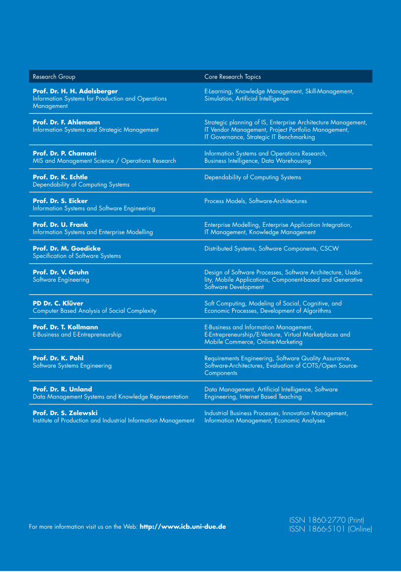
�������������������
���������������������������������������������������
Marian Daun, Markus Fockel,Jörg Holtmann, Bastian Tenbergen
Case Study “Body Control Module”
ICB-Research Report No. 55
May 2013
Research Group Core Research Topics
Prof. Dr. H. H. AdelsbergerInformation Systems for Production and OperationsManagement
E-Learning, Knowledge Management, Skill-Management,Simulation, Artificial Intelligence
Prof. Dr. F. AhlemannInformation Systems and Strategic Management
Strategic planning of IS, Enterprise Architecture Management, IT Vendor Management, Project Portfolio Management, IT Governance, Strategic IT Benchmarking
Prof. Dr. P. ChamoniMIS and Management Science / Operations Research
Information Systems and Operations Research, Business Intelligence, Data Warehousing
Prof. Dr. K. EchtleDependability of Computing Systems
Dependability of Computing Systems
Prof. Dr. S. EickerInformation Systems and Software Engineering
Process Models, Software-Architectures
Prof. Dr. U. FrankInformation Systems and Enterprise Modelling
Enterprise Modelling, Enterprise Application Integration,IT Management, Knowledge Management
Prof. Dr. M. GoedickeSpecification of Software Systems
Distributed Systems, Software Components, CSCW
Prof. Dr. V. Gruhn Software Engineering
Design of Software Processes, Software Architecture, Usabi-lity, Mobile Applications, Component-based and Generative Software Development
PD Dr. C. Klüver Computer Based Analysis of Social Complexity
Soft Computing, Modeling of Social, Cognitive, and Economic Processes, Development of Algorithms
Prof. Dr. T. Kollmann E-Business and E-Entrepreneurship
E-Business and Information Management, E-Entrepreneurship/E-Venture, Virtual Marketplaces and Mobile Commerce, Online-Marketing
Prof. Dr. K. PohlSoftware Systems Engineering
Requirements Engineering, Software Quality Assurance,Software-Architectures, Evaluation of COTS/Open Source-Components
Prof. Dr. R. UnlandData Management Systems and Knowledge Representation
Data Management, Artificial Intelligence, Software Engineering, Internet Based Teaching
Prof. Dr. S. ZelewskiInstitute of Production and Industrial Information Management
Industrial Business Processes, Innovation Management,Information Management, Economic Analyses
For more information visit us on the Web: http://www.icb.uni-due.de
ISSN 1860-2770 (Print)ISSN 1866-5101 (Online)
55Goal-Scenario-Oriented Requirements Engineering for Func-
tional Decomposition with Bidirectional Transformation to
Controlled Natural Language