case studies cs 4 - worldofpumps.com · case studies – cs 4 segment – affinity laws \ pumping...
TRANSCRIPT

1
CASE STUDIES – CS 4
Segment – Affinity Laws \ Pumping System
Topic/ case – Cooling water pumps at coke oven, Tata Steel –
Low discharge due to high pressure drop across chillers
Description of the case – Tata Steel has installed 10”/12” size cooling water pump in
their coke plant.
The rated discharge of the pumps was selected such that the required discharge could
be obtained from two pumps, while the others could be used as stand-by units. In
practice, however, they have to run at least four pumps to get the required flow rate.
Investigation revealed that the large pressure drop across the chillers has moved the
system curve to a higher level of head. The company is considering refurbishing the
cooling coils in the chillers to reduce system loss and also, at the same time, using
larger impellers to improve the flow from each pump.
Question for discussion-
2. What are the diagnostic steps to determine the actual head and capacity of
the pumps in operation?
3. How do we determine the new impeller diameter of the existing pumps for
larger head?
4. How do we draw the new pump H-Q and new system curves and estimate
flow from each pump?
PUMPSENSE CS4 1/17
2
Pump System Data Provided by Tata Steel
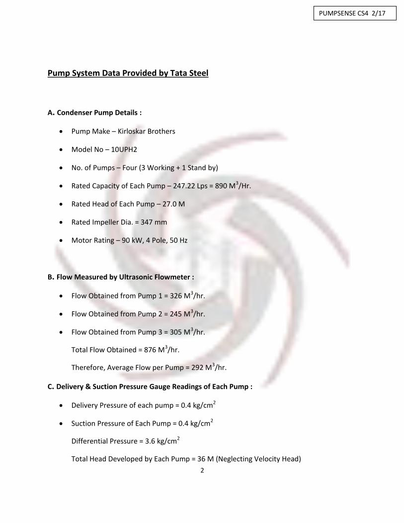
A. Condenser Pump Details :
Pump Make – Kirloskar Brothers
Model No – 10UPH2
No. of Pumps – Four (3 Working + 1 Stand by)
Rated Capacity of Each Pump – 247.22 Lps = 890 M3/Hr.
Rated Head of Each Pump – 27.0 M
Rated Impeller Dia. = 347 mm
Motor Rating – 90 kW, 4 Pole, 50 Hz
B. Flow Measured by Ultrasonic Flowmeter :
Flow Obtained from Pump 1 = 326 M3/hr.
Flow Obtained from Pump 2 = 245 M3/hr.
Flow Obtained from Pump 3 = 305 M3/hr.
Total Flow Obtained = 876 M3/hr.
Therefore, Average Flow per Pump = 292 M3/hr.
C. Delivery & Suction Pressure Gauge Readings of Each Pump :
Delivery Pressure of each pump = 0.4 kg/cm2
Suction Pressure of Each Pump = 0.4 kg/cm2
Differential Pressure = 3.6 kg/cm2
Total Head Developed by Each Pump = 36 M (Neglecting Velocity Head)
PUMPSENSE CS4 2/17

3
D. Inlet & Outlet Pressure of Chiller-Condensers :
Chiller Unit 1
Inlet Pressure = 3.8 kg/cm2
Outlet Pressure = 1.2 kg/cm2
Therefore, Head drop across Chiller Unit 1 is 26 M
Chiller Unit 2
Inlet Pressure = 3.8 kg/cm2
Outlet Pressure = 1.5 kg/cm2
Therefore, Head drop across Chiller Unit 2 is 23 M
Chiller Unit 3
Inlet Pressure = 3.8 kg/cm2
Outlet Pressure = 1.8 kg/cm2
Therefore, Head drop across Chiller Unit 3 is 20 M
Avg. head drop across chiller unit is 23 M.
E. Establishing the System resistance Curve for the Existing System:
The total head of the pumping system and the system resistance curve under the existing condition is
established in the following manner:
Head Developed by each pump = 36 M
Avg. flow from each pump = 292 M3/Hr.
Friction Head drop in the discharge pipe between pump & chiller condenser(avg.) = 2 M
Friction Head drop in the piping beyond the chiller condenser up to cooling tower = 3 M
(assumed)
Total friction head drop in the system corresponding to 876 M3/Hr.
PUMPSENSE CS4 3/17
4
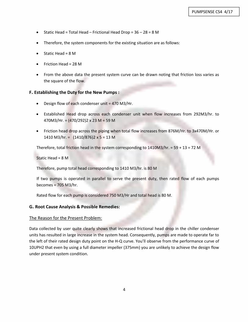
Static Head = Total Head – Frictional Head Drop = 36 – 28 = 8 M
Therefore, the system components for the existing situation are as follows:
Static Head = 8 M
Friction Head = 28 M
From the above data the present system curve can be drawn noting that friction loss varies as
the square of the flow.
F. Establishing the Duty for the New Pumps :
Design flow of each condenser unit = 470 M3/Hr.
Established Head drop across each condenser unit when flow increases from 292M3/hr. to
470M3/Hr. = (470/292)2 x 23 M = 59 M
Friction head drop across the piping when total flow increases from 876M/Hr. to 3x470M/Hr. or
1410 M3/hr. = (1410/876)2 x 5 = 13 M
Therefore, total friction head in the system corresponding to 1410M3/hr. = 59 + 13 = 72 M
Static Head = 8 M
Therefore, pump total head corresponding to 1410 M3/hr. is 80 M
If two pumps is operated in parallel to serve the present duty, then rated flow of each pumps
becomes = 705 M3/hr.
Rated flow for each pump is considered 750 M3/Hr and total head is 80 M.
G. Root Cause Analysis & Possible Remedies:
The Reason for the Present Problem:
Data collected by user quite clearly shows that increased frictional head drop in the chiller condenser
units has resulted in large increase in the system head. Consequently, pumps are made to operate far to
the left of their rated design duty point on the H-Q curve. You’ll observe from the performance curve of
10UPH2 that even by using a full diameter impeller (375mm) you are unlikely to achieve the design flow
under present system condition.
PUMPSENSE CS4 4/17
5
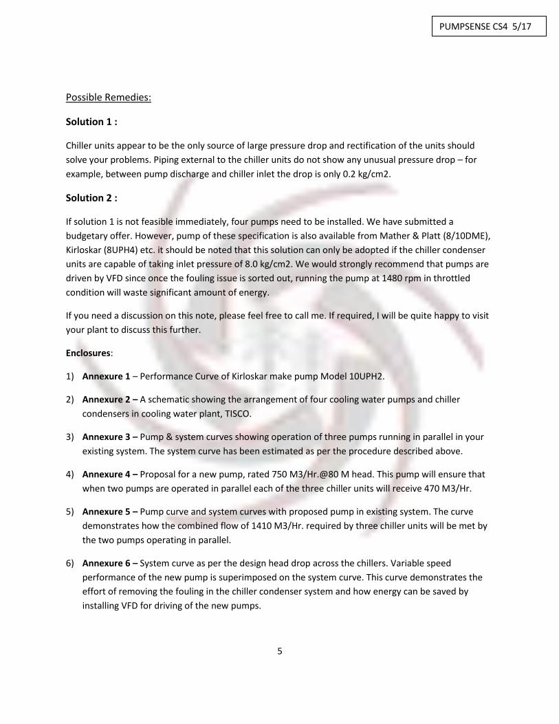
Possible Remedies:
Solution 1 :
Chiller units appear to be the only source of large pressure drop and rectification of the units should
solve your problems. Piping external to the chiller units do not show any unusual pressure drop – for
example, between pump discharge and chiller inlet the drop is only 0.2 kg/cm2.
Solution 2 :
If solution 1 is not feasible immediately, four pumps need to be installed. We have submitted a
budgetary offer. However, pump of these specification is also available from Mather & Platt (8/10DME),
Kirloskar (8UPH4) etc. it should be noted that this solution can only be adopted if the chiller condenser
units are capable of taking inlet pressure of 8.0 kg/cm2. We would strongly recommend that pumps are
driven by VFD since once the fouling issue is sorted out, running the pump at 1480 rpm in throttled
condition will waste significant amount of energy.
If you need a discussion on this note, please feel free to call me. If required, I will be quite happy to visit
your plant to discuss this further.
Enclosures:
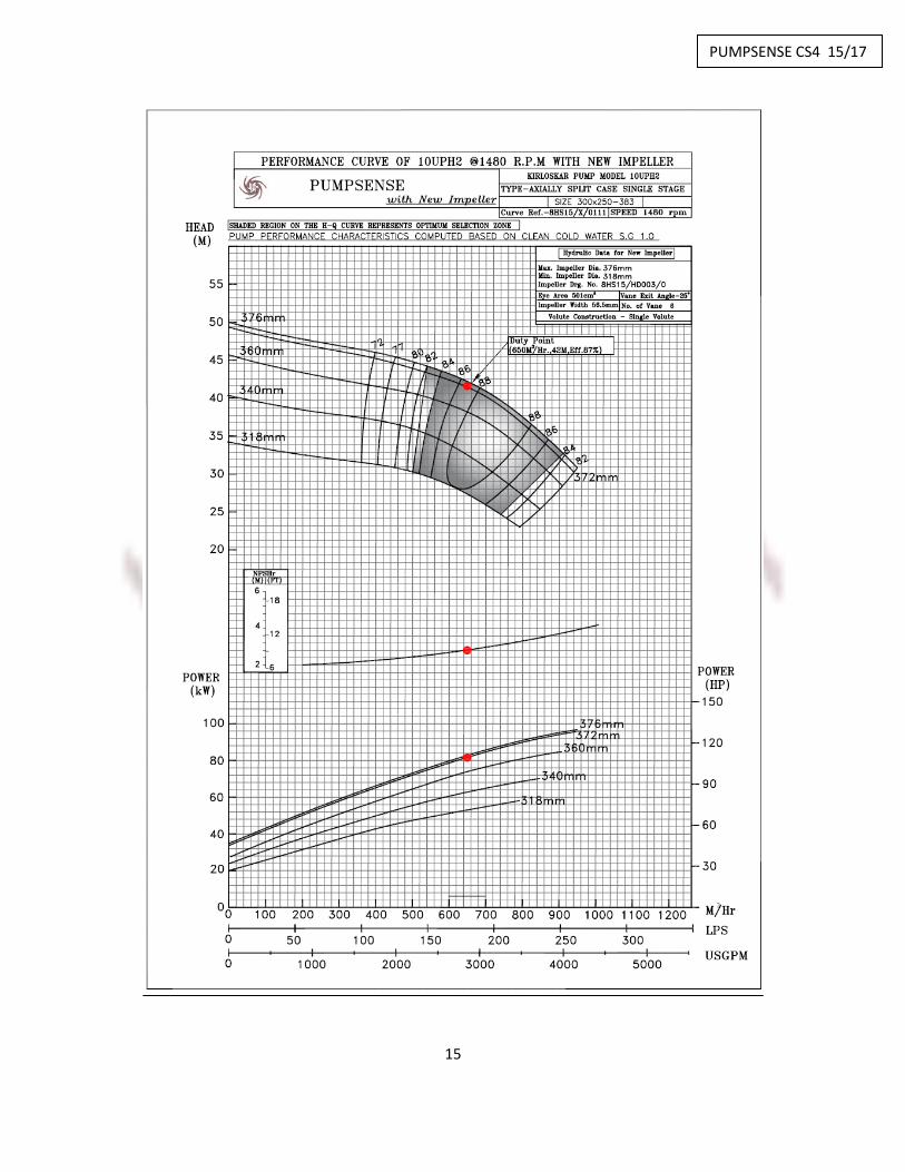
1) Annexure 1 – Performance Curve of Kirloskar make pump Model 10UPH2.
2) Annexure 2 – A schematic showing the arrangement of four cooling water pumps and chiller
condensers in cooling water plant, TISCO.
3) Annexure 3 – Pump & system curves showing operation of three pumps running in parallel in your
existing system. The system curve has been estimated as per the procedure described above.
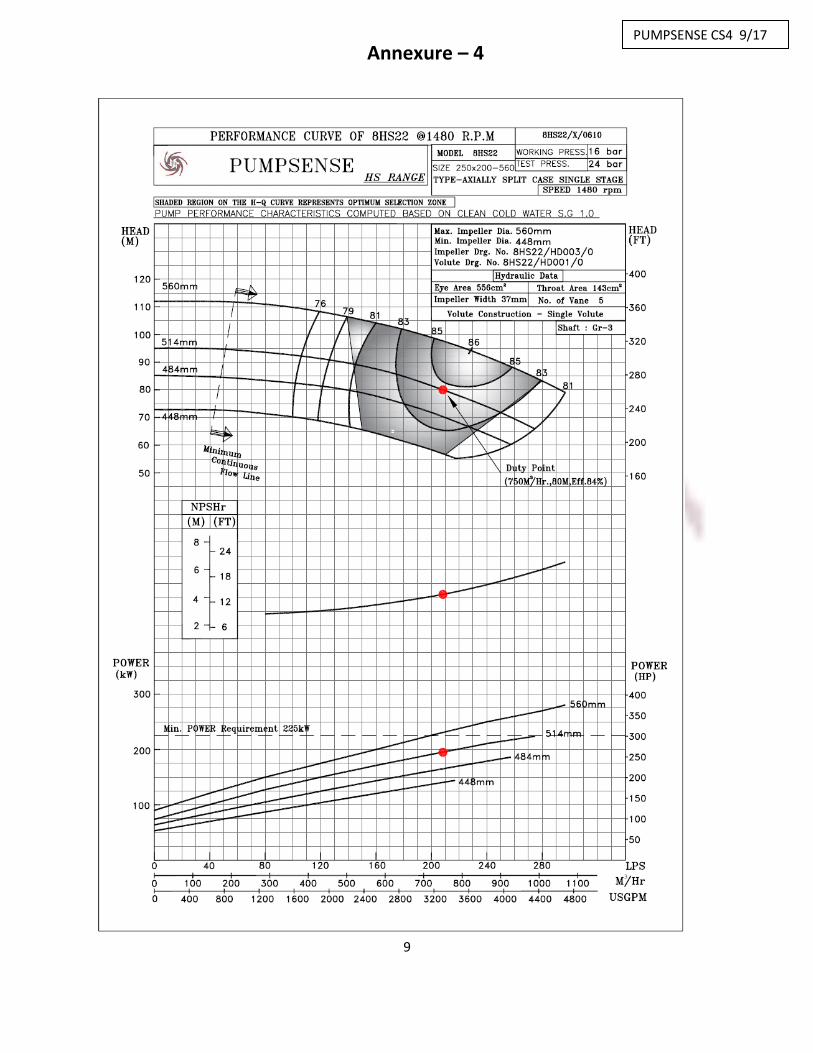
4) Annexure 4 – Proposal for a new pump, rated 750 M3/Hr.@80 M head. This pump will ensure that
when two pumps are operated in parallel each of the three chiller units will receive 470 M3/Hr.
5) Annexure 5 – Pump curve and system curves with proposed pump in existing system. The curve
demonstrates how the combined flow of 1410 M3/Hr. required by three chiller units will be met by
the two pumps operating in parallel.
6) Annexure 6 – System curve as per the design head drop across the chillers. Variable speed
performance of the new pump is superimposed on the system curve. This curve demonstrates the
effort of removing the fouling in the chiller condenser system and how energy can be saved by
installing VFD for driving of the new pumps.
PUMPSENSE CS4 5/17

6
Annexure – 1
PUMPSENSE CS4 6/17

7
PUMPSENSE CS4 7/17

8
Annexure –
3
PUMPSENSE CS4 8/17
9
Annexure – 4
PUMPSENSE CS4 9/17

10
PUMPSENSE CS4 10/17

11
PUMPSENSE CS4 11/17

12
Solution 1
Renovation of Existing System
Rotating Element for Raw Water Pump – Technical Specifications
A. Introduction – Coke Oven cooling water system at Tata Steel, Jamshedpur, has four cooling
water pumps supplied by Kirloskar Brothers Ltd, Pune. The pump casings are in good working
order and it is intended to replace the rotating elements of these existing pumps to meet the
altered flow and head conditions. The new rotating elements should include energy efficient
impellers and ensure at least four years of uninterrupted working life.
B. Existing Pump – Following is the brief description of the existing pump units:
No of pumps - Four
Make: Kirloskar Brothers Ltd, Pune, India
Type: Axially split case
Delivery / Suction Branch Sizes: 10”/12”
Casing Design: Single volute, side suction, side discharge.
Rated Capacity: 247.22 l/s – 890 m3/hr
Rated head: 27.0 m
Rotational Speed: 1480 rpm
Impeller Diameter – 347 mm
Driver: 90 KW, 4 pole, 50 Hz, 415V TEFC motor
C. Scope of Work: We have considered the following scope of work:
1. Design and development a new impeller for 650 m3/hr at 42 m total head.
2. Measurement of internal dimensions of the existing pump and rotating element at site in
order to clearly establish the site constraints for optimizing the design of rotating element.
3. Design of shaft and other rotating components as per the list of components included in this
document.
4. Preparation of final data sheet and of machining drawings for components of the rotating
element. Submission of these documents to Tata Steel for their approval and future
reference.
5. Manufacture of components based on approved drawings
6. Submission of all quality assurance documents as per the list included in this document.
7. Installation of the rotating element at site. Conducting trial run of the pump with the new
rotating element in association with Tata Steel engineers.
8. Demonstrating to Tata Steel that performance guarantee has been met
PUMPSENSE CS4 12/17

13
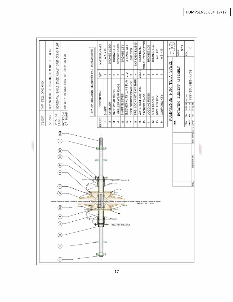
Components and their material specifications
Sr. No Component Material Specifications
1 Impeller Gun Metal BS1400 LG2
2 Case Wear Rings Bronze BS1400 LB2
3 Shaft AISI 410
4 Sleeves and sleeve
nuts
Zinc Free Bronze BS1400 CT1
5 Stuffing box bushes Bronze BS1400 LB2
6 Glands Bronze BS1400 LG2
7 Lantern ring Bronze BS1400 LG2
8 Water deflector Neoprene Rubber
9 Bearings SKF 6309
10 Gland packing PTFE
Please note that the above list is indicative only and any additional components / consumables
needed to successfully carry out the replacement of the existing rotating element will be in our
scope of supply.
D. Quality Assurance Documents – The following quality assurance documents will be submitted
by us:
Component QA Documents
Impeller Dynamic balancing report as per ISO 1940 G 6.3
Chemical test report, dimensional report
Shaft Ultrasonic test report, chemical and physical test report, dimensional
report
Wear Rings Hardness, chemical test and dimensional reports
Shaft sleeves Chemical test and hardness reports
PUMPSENSE CS4 13/17

14
E. Data sheets – We are attaching a preliminary data sheets containing key information relating to
dimensions of the components and their design features. Preliminary data sheet should be
considered indicative only and has been included to indicate our understanding of the design
task and the design approach proposed by us. In the event of an order, we willl submit a final
data sheet for approval when all of the design elements have been finalised. We, however,
confirm that key hydraulic design data – rated capacity, head, efficiency and NPSHR shall not be
changed and retained as per the preliminary data sheet.
F. Meeting performance guarantee – Fulfilment of performance guarantee will be ensured by
taking suction and delivery pressure gauge readings and power consumption at the motor
terminals for pre-defined number of flow conditions before and after the installation of new
rotating element. The method of fulfilment of performance guarantee will be discussed in detail
with Tata Steel during pre-award discussions to arrive at mutually agreed procedure.
PUMPSENSE CS4 14/17
15
PUMPSENSE CS4 15/17

16
PUMPSENSE CS4 16/17
17
PUMPSENSE CS4 17/17