carl goldberg products ex-treme 330 3-d
TRANSCRIPT

CARL GOLDBERG PRODUCTS
EX-TREME 330 3-D
© 2002 Carl Goldberg Products, Inc.

WARNING! THIS IS NOT A TOY!
THIS IS NOT A BEGINNERS AIRPLANE
This R/C kit and the model you will build from it is not a toy! It is capable of serious bodily harm and property damage. It is your responsibility, and yours alone - to build this kit correctly, properly install all R/C components and flying gear (engine, tank, radio, pushrods, etc. and to test the model and fly it only with experienced, competent help, using commonsense and in accordance with all safety standards as set forth in the Academy of Model Aeronautics Safety Code. It is suggested that you join the AMA and become properly insured before attempting to fly this model. If you are just starting R/C modeling, consult your local hobby dealer or write to the Academy of Model Aeronautics to find an experienced instructor in your area.
Write to: Academy of Model Aeronautics, 5151 Memorial Dr. Muncie, IN 47302
LIMITED WARRANTY
Carl Goldberg Products is proud of the care and attention that goes into the manufacture of parts for its model kits. The company warrants that for a period of 90 days, it will replace, at the buyers request, any part or material shown to the company’s satisfaction to have been defective in workmanship or material at the time of purchase.
No other warranty of any kind, expressed or implied, is made with respect to the merchandise sold by the company. The buyer acknowledges and understands that he is purchasing only a component kit from which the buyer will himself construct a finished flying model airplane. The company is neither the manufacturer of such a flying model airplane, nor a seller of it. The buyer hereby assumes the risk and all liability for personal or property damage or injury arising out of the buyers use of the components or the finished flying model airplane, whenever any such damage or injury shall occur.
Any action brought forth against the company, based on the breach of the contract of sale to the buyer, or on any alleged warranty there under, must be brought within one year of the date of such sale, or there after be barred. This one-year limitation is imposed by agreement of the parties as permitted by the laws of the state of Georgia.
Important Information Covering coming loose is not COVERED UNDER WARRANTY. Due to temperature changes the plane may develop some wrinkles in the covering that you will need to remove with an iron. Be sure to seal the edges down first so that you do not cause the covering to shrink and leave exposed areas of wood. Please inspect the plane before beginning to assemble to make sure you are happy with it. After assembly has begun you cannot return the kit. If you find a problem before beginning to assemble the plane you must contact us, please do not return it to the dealer.
© 2002 Carl Goldberg Products, Inc.

EX-TREME 330 3-D ARF
PARTS LAYOUT
O ne P iece W ingA ilerons
F uselage
A lim inum L anding G ear
M ain W heels
H ardw ood E ngine M ount
E levator
R udder
H orizontal S tab
V ertical S tab
F uel T ank
© 2002 Carl Goldberg Products, Inc. Page - 3
EX-TREME 330 3-D ARF
BUILDING INSTRUCTIONS
Before starting to build this kit, we urge you to read through these instructions. They contain some important building sequences as well as instructions and warnings concerning the assembly and use of the model.
We expect that you have some building experience to take on this model. However, every minute detail is not covered. This is not a basic trainer. The instructions together with the simplicity of this kit will allow you to produce a first class EX-TREME 330 3-D.
BUILDING SUPPLIES NEEDED
Hobby knife w/ #11 blade
Thin Zap CA
30 Minute Z-poxy
Thread lock
Wire cutters
Pliers
Drill with bits: 1/8”, 5/32”
Phillips and standard screwdriver
Small clamps
Masking tape
Tape measure
Washable marker
Paper towels
Rubbing alcohol
See the list at the end of the instruction book for a list of additional R/C equipment you will need to complete the EX-TREME 330 3-D.
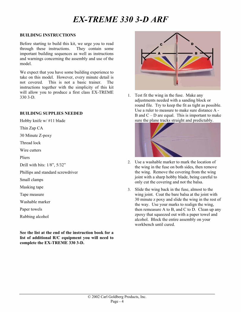
1. Test fit the wing in the fuse. Make any
adjustments needed with a sanding block or round file. Try to keep the fit as tight as possible. Use a ruler to measure to make sure distance A - B and C – D are equal. This is important to make sure the plane tracks straight and predictably.
2. Use a washable marker to mark the location of
the wing in the fuse on both sides, then remove the wing. Remove the covering from the wing joint with a sharp hobby blade, being careful to only cut the covering and not the balsa.
3. Slide the wing back in the fuse, almost to the wing joint. Coat the bare balsa at the joint with 30 minute z poxy and slide the wing in the rest of the way. Use your marks to realign the wing, then remeasure A to B, and C to D. Clean up any zpoxy that squeezed out with a paper towel and alcohol. Block the entire assembly on your workbench until cured.
© 2002 Carl Goldberg Products, Inc. Page - 4
EX-TREME 330 3-D ARF
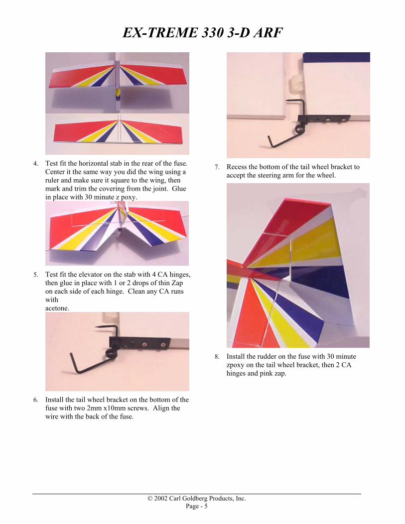
4. Test fit the horizontal stab in the rear of the fuse.
Center it the same way you did the wing using a ruler and make sure it square to the wing, then mark and trim the covering from the joint. Glue in place with 30 minute z poxy.
5. Test fit the elevator on the stab with 4 CA hinges,
then glue in place with 1 or 2 drops of thin Zap on each side of each hinge. Clean any CA runs with acetone.
6. Install the tail wheel bracket on the bottom of the
fuse with two 2mm x10mm screws. Align the wire with the back of the fuse.
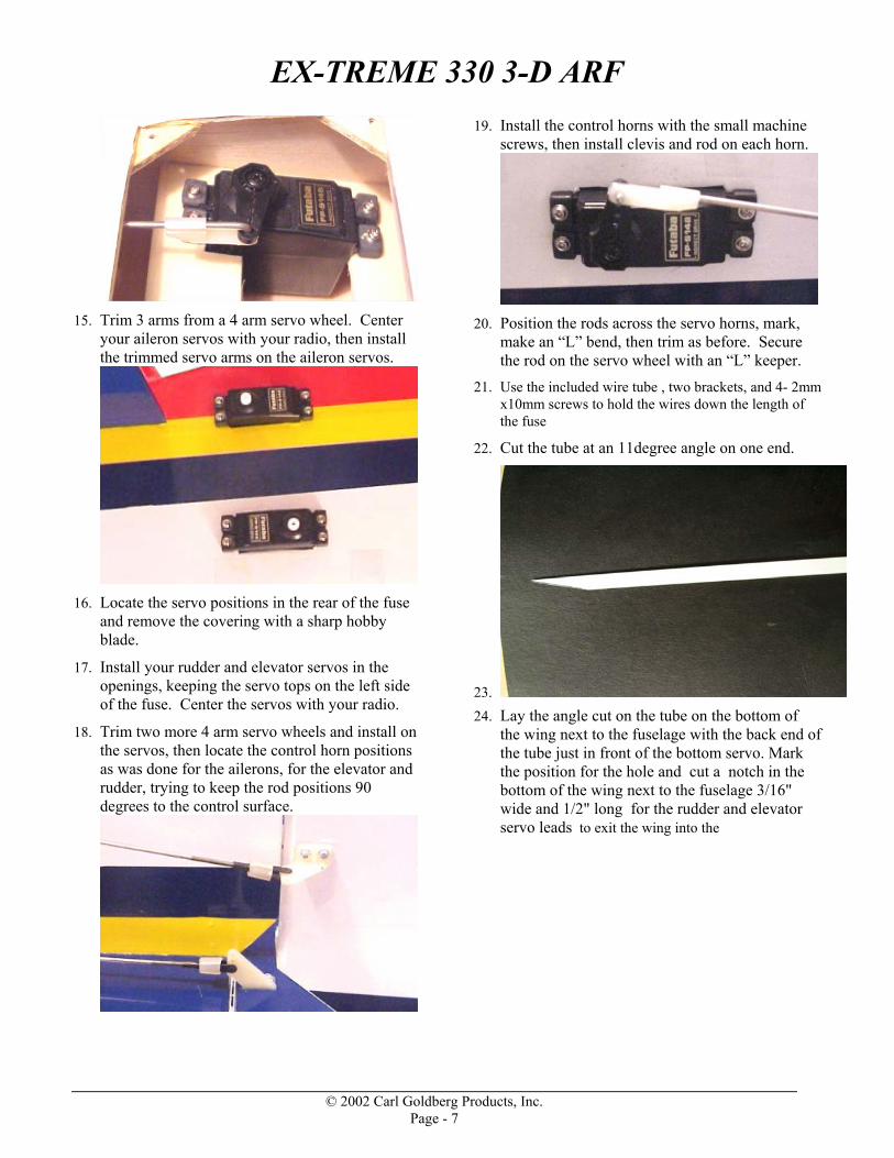
7. Recess the bottom of the tail wheel bracket to
accept the steering arm for the wheel.
8. Install the rudder on the fuse with 30 minute
zpoxy on the tail wheel bracket, then 2 CA hinges and pink zap.
© 2002 Carl Goldberg Products, Inc. Page - 5

EX-TREME 330 3-D ARF
9. Install the tail wheel on the bracket using a small
inner diameter wheel collar and set screw on each side of the wheel. Use thread lock on each set screw.
10. Trial fit, then install an aileron on each side of
the wing with 4 CA hinges and pink zap. Make sure the wing tip and aileron tip are aligned before you glue.
11. Install two aileron servos and one throttle servo
in the wing. You may need to open the servo trays to accept the size of your servos. Use a hobby blade or razor saw to open the servo trays. The aileron servos should be located to the outside of the servo trays from the fuse, the throttle servo needs to be close to the fuse.
12. Position the aileron control rods off the servos,
toward the ailerons, keeping the rods 90 degrees to the ailerons. Mark the position of the aileron control horns, then install them with the 2mm x 20mm machine screws and backing plates.
13. Trim a hole using a sharp hobby blade, just
behind the radio hatch on each side of the wing, aligned with the servo, for the aileron control rod.
14. Use a clevis on the threaded end of the control
rod and install one on each control horn. Lay the rod across the servo arm, then make an “L” bend at each intersection. Trim each rod to ¼” from the bend, install in the horn, and secure with an “L” keeper. Place a small piece of fuel tubing on each clevis to lock in place.
© 2002 Carl Goldberg Products, Inc. Page - 6
EX-TREME 330 3-D ARF
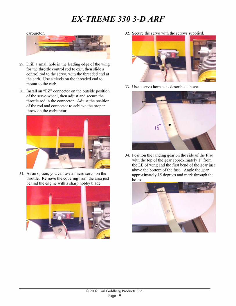
15. Trim 3 arms from a 4 arm servo wheel. Center
your aileron servos with your radio, then install the trimmed servo arms on the aileron servos.
16. Locate the servo positions in the rear of the fuse
and remove the covering with a sharp hobby blade.
17. Install your rudder and elevator servos in the openings, keeping the servo tops on the left side of the fuse. Center the servos with your radio.
18. Trim two more 4 arm servo wheels and install on the servos, then locate the control horn positions as was done for the ailerons, for the elevator and rudder, trying to keep the rod positions 90 degrees to the control surface.
19. Install the control horns with the small machine screws, then install clevis and rod on each horn.
20. Position the rods across the servo horns, mark,
make an “L” bend, then trim as before. Secure the rod on the servo wheel with an “L” keeper.
21. Use the included wire tube , two brackets, and 4- 2mm x10mm screws to hold the wires down the length of the fuse
22. Cut the tube at an 11degree angle on one end.
23. 24. Lay the angle cut on the tube on the bottom of
the wing next to the fuselage with the back end of the tube just in front of the bottom servo. Mark the position for the hole and cut a notch in the bottom of the wing next to the fuselage 3/16" wide and 1/2" long for the rudder and elevator servo leads to exit the wing into the
© 2002 Carl Goldberg Products, Inc. Page - 7

EX-TREME 330 3-D ARF
tube.
25. Attach the tube to the side of the fuselage with
the two brackets and 4 sheet metal screws. You can now run you wires from the rear servos through the tube into the wing.
26. Trial fit your engine on the right side of the fuse.
You can open the rails up slightly if needed. Slide the engine forward so you have at least ¼” clearance from the front of the prop hub to the front of the fuse. Mark the location, remove your motor, then drill for the 3mm engine mounting bolts.
27. Mount your engine to the fuse with 3mm x
20mm bolts, washers, and lock nuts. There is no need to add any washers under the motor as the right thrust is built into the motor mounts.
28. Prepare and install a servo wheel on the throttle
servo as was done with the control surfaces. Make sure your servo is at low position and the travel matches up with the travel of the
© 2002 Carl Goldberg Products, Inc. Page - 8
EX-TREME 330 3-D ARF
carburetor.
29. Drill a small hole in the leading edge of the wing
for the throttle control rod to exit, then slide a control rod to the servo, with the threaded end at the carb. Use a clevis on the threaded end to mount to the carb.
30. Install an “EZ” connector on the outside position of the servo wheel, then adjust and secure the throttle rod in the connector. Adjust the position of the rod and connector to achieve the proper throw on the carburetor.
31. As an option, you can use a micro servo on the
throttle. Remove the covering from the area just behind the engine with a sharp hobby blade.
32. Secure the servo with the screws supplied.
33. Use a servo horn as is described above.
34. Position the landing gear on the side of the fuse
with the top of the gear approximately 1” from the LE of wing and the first bend of the gear just above the bottom of the fuse. Angle the gear approximately 15 degrees and mark through the holes.
© 2002 Carl Goldberg Products, Inc. Page - 9

EX-TREME 330 3-D ARF
35. Drill the holes for the gear, then install the gear using the 3mm x 30mm bolts and lock nuts.
36. Install the axles in the end of the landing gear
using the 4mm lock nuts.
37. Install the first collar and set screw on the axle.
38. Install the large wheel, then the second collar and
set screw to secure the wheel. Leave a small amount of space from the wheel hub to allow the wheel to turn freely. Use thread lock on the set
screws.
39. Lay out the parts for the fuel tank assembly.
Check the tank for any debris inside, then check the fit of the stopper. You may need to remove some flash with a sharp hobby knife.
40. Bend the long fuel tube so 1/3 of it is bent up at
45 degrees.
41. Assemble the stopper as shown, with the small
washer to the inside of the stopper, then the stopper, and the large washer. Secure with the machine screw. Just start the screw for now.
© 2002 Carl Goldberg Products, Inc. Page - 10
EX-TREME 330 3-D ARF
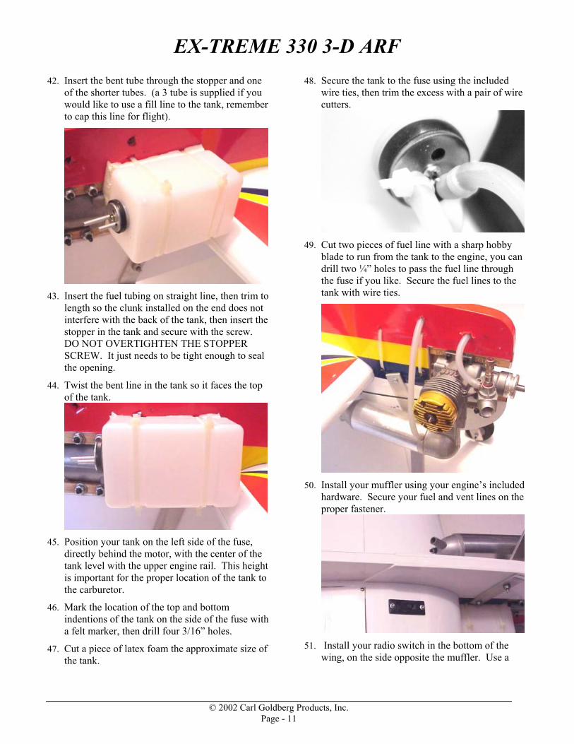
42. Insert the bent tube through the stopper and one of the shorter tubes. (a 3 tube is supplied if you would like to use a fill line to the tank, remember to cap this line for flight).
43. Insert the fuel tubing on straight line, then trim to
length so the clunk installed on the end does not interfere with the back of the tank, then insert the stopper in the tank and secure with the screw. DO NOT OVERTIGHTEN THE STOPPER SCREW. It just needs to be tight enough to seal the opening.
44. Twist the bent line in the tank so it faces the top of the tank.
45. Position your tank on the left side of the fuse,
directly behind the motor, with the center of the tank level with the upper engine rail. This height is important for the proper location of the tank to the carburetor.
46. Mark the location of the top and bottom indentions of the tank on the side of the fuse with a felt marker, then drill four 3/16” holes.
47. Cut a piece of latex foam the approximate size of the tank.
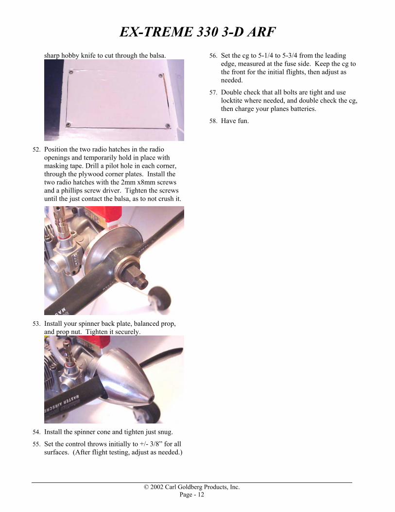
48. Secure the tank to the fuse using the included wire ties, then trim the excess with a pair of wire cutters.
49. Cut two pieces of fuel line with a sharp hobby
blade to run from the tank to the engine, you can drill two ¼” holes to pass the fuel line through the fuse if you like. Secure the fuel lines to the tank with wire ties.
50. Install your muffler using your engine’s included
hardware. Secure your fuel and vent lines on the proper fastener.
51. Install your radio switch in the bottom of the
wing, on the side opposite the muffler. Use a
© 2002 Carl Goldberg Products, Inc. Page - 11
EX-TREME 330 3-D ARF
sharp hobby knife to cut through the balsa.
52. Position the two radio hatches in the radio
openings and temporarily hold in place with masking tape. Drill a pilot hole in each corner, through the plywood corner plates. Install the two radio hatches with the 2mm x8mm screws and a phillips screw driver. Tighten the screws until the just contact the balsa, as to not crush it.
53. Install your spinner back plate, balanced prop,
and prop nut. Tighten it securely.
54. Install the spinner cone and tighten just snug.
55. Set the control throws initially to +/- 3/8” for all surfaces. (After flight testing, adjust as needed.)
56. Set the cg to 5-1/4 to 5-3/4 from the leading edge, measured at the fuse side. Keep the cg to the front for the initial flights, then adjust as needed.
57. Double check that all bolts are tight and use locktite where needed, and double check the cg, then charge your planes batteries.
58. Have fun.
© 2002 Carl Goldberg Products, Inc. Page - 12
EX-TREME 330 3-D ARF
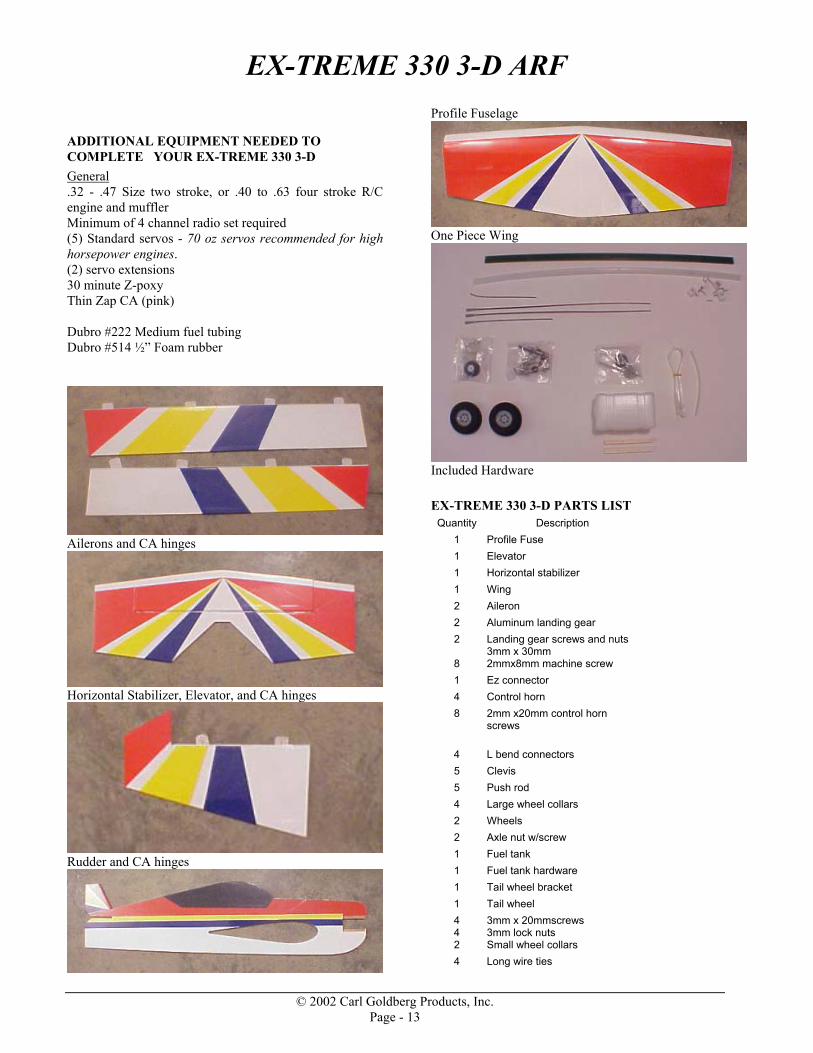
ADDITIONAL EQUIPMENT NEEDED TO COMPLETE YOUR EX-TREME 330 3-D General .32 - .47 Size two stroke, or .40 to .63 four stroke R/C engine and muffler Minimum of 4 channel radio set required (5) Standard servos - 70 oz servos recommended for high horsepower engines. (2) servo extensions 30 minute Z-poxy Thin Zap CA (pink) Dubro #222 Medium fuel tubing Dubro #514 ½” Foam rubber
Ailerons and CA hinges
Horizontal Stabilizer, Elevator, and CA hinges
Rudder and CA hinges
Profile Fuselage
One Piece Wing
Included Hardware EX-TREME 330 3-D PARTS LIST
Quantity Description 1 Profile Fuse 1 Elevator 1 Horizontal stabilizer 1 Wing 2 Aileron 2 Aluminum landing gear 2 Landing gear screws and nuts
3mm x 30mm 8 2mmx8mm machine screw 1 Ez connector 4 Control horn 8 2mm x20mm control horn
screws
4 L bend connectors 5 Clevis 5 Push rod 4 Large wheel collars 2 Wheels 2 Axle nut w/screw 1 Fuel tank 1 Fuel tank hardware 1 Tail wheel bracket 1 Tail wheel 4 4
3mm x 20mmscrews 3mm lock nuts
2 Small wheel collars 4 Long wire ties
© 2002 Carl Goldberg Products, Inc. Page - 13

EX-TREME 330 3-D ARF
14 CA hinges 1 Wire tube 2 Wire tube brackets 4 2mm x 10mm screws for tube
brackets 1 Decal set
© 2002 Carl Goldberg Products, Inc. Page - 14
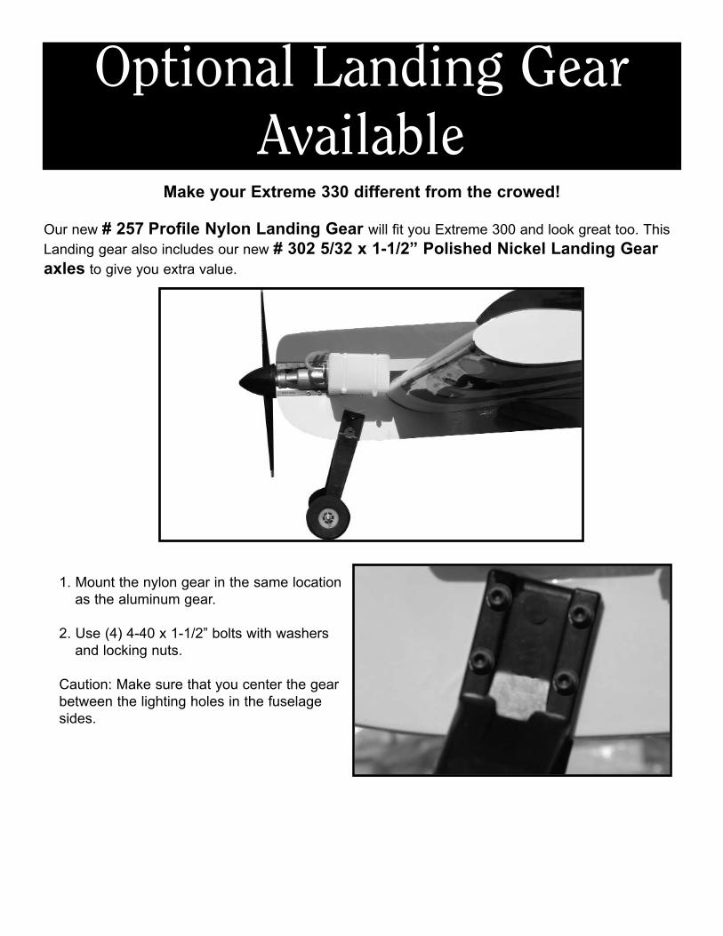
Optional Landing GearAvailable
Make your Extreme 330 different from the crowed!
Our new # 257 Profile Nylon Landing Gear will fit you Extreme 300 and look great too. ThisLanding gear also includes our new # 302 5/32 x 1-1/2” Polished Nickel Landing Gearaxles to give you extra value.
1. Mount the nylon gear in the same locationas the aluminum gear.
2. Use (4) 4-40 x 1-1/2” bolts with washers and locking nuts.
Caution: Make sure that you center the gearbetween the lighting holes in the fuselagesides.

EX-TREME 330 3-D ARF
The Elevator This maneuver has your plane drop vertically in a nose high attitude, depending on wind conditions any where from a 45 degree angle in low wind to almost backwards in higher wind conditions. To perform it, at a high altitude with high rates on, pull your throttle back and feed in the elevator until you have the full high rate applied. Use the rudder to guide the plane, and adjust attitude with minor throttle inputs. You will loose altitude quickly, to recover, apply full power and fly out level. Watch out for getting too low or applying too much rudder, it could cause the plane to snap.
The Harrier This maneuver has your plane in very slow forward flight in a nose high 45 degree attitude. To perform it, enter the same way as you would an elevator, then feed in power until the plane maintains altitude and starts to fly forward at a nose high attitude. Maintain it by holding up elevator and adjusting power, use the rudder to change direction. Using ailerons may cause the plane to snap and should be avoided. Add power and push the nose back over to recover.
© 2002 Carl Goldberg Products, Inc. Page - 15

EX-TREME 330 3-D ARF
The Waterfall This maneuver has your plane flipping around the axis of the wing, while dropping. Starting from a high altitude, go to low throttle and gradually pull the nose up to near vertical. Just when the plane is about the stall, give it full down elevator and full power. Make attitude corrections with the rudder and ailerons to keep the plane flipping on axis. Cut the throttle and hold full down elevator as the plane flips around to nose high again, add power to flip it over again. Watch your altitude as to not get too close to the ground. Neutralize the elevator and add power to recover.
The Blender This is a violent maneuver that starts with a vertical rolling dive that stops the descent as it changes into a flat spin. Start at a good high altitude, go to low throttle and push the nose down into a straight dive. Feed in full left aileron and complete 3 rolls, then immediately move your transmitter sticks to an inverted snap position, down elevator, left aileron, right rudder, all full throw. Now feed in high throttle to flatten the spin and stop the altitude loss. Recover by neutralizing the rudder and ailerons, and holding a little down elevator. After you gain some airspeed you can roll out to upright. Use caution as this is a violent and high G mauver that will put a great deal of stress on the airframe.
© 2002 Carl Goldberg Products, Inc. Page - 16