career profile of
TRANSCRIPT

Career Profile of Er. A.S. Bhagat Consultant, Quadricon Pvt Ltd, Mumbai Recipient of S.B. Joshi Memorial Award for Excellence in Bridge & Structural Engineering for the year 2003, cited by Alumni Association of College of Engineering, Pune Date of Birth:
• 12th September, 1930 Educational Qualification and Training:
• Mechanical Engineer • Career in Manufacturing of bridge construction equipment
Professional Experience and Training:
• Construction of several steel Quadricon bridges in strategic locations of Himalayan mountains
• Innovation of the Unishear joint • Jointly with his wife, Mrs. Shakuntala Bhagat, outstanding civil engineer
and past professor of IIT, Bombay and daughter of Late S.B. Joshi, carried out research, investigations, evaluations and applications of non-conventional innovative ideas and products work of ‘Unishear Connector’, the ideal structural connection system
• Innovative design of special structural steel elements to meet the higher standards of Structural efficiency of Quadricon
• Innovative open spandrel Arch Bridge at Solding across 90 m deep gorge, erected in incremental cantilever without intermediate support.
• Record time construction in 18 months of flyover on eastern express highway at Mumbai without hindrance to traffic
• Export of Quadricon modular components for number of bridges in Bangladesh and Philippines
• Commercial operation in USA in the name of Quadricon Bridge System (QBS)

Honors & Awards:
• Highest Award for the invention of Unishear connection from Invention Promotion Board in 1973
• Number of products are patented in India and other countries like a) Unishear connector b) Mobile Gantry system c) Prefabricated prestressed structural system d) Bridging system across roads, rails, etc.
Details of Contact: A/8, Ferreira Annexe, Shitaldevi Temple Road, Mahim West, Mumbai 400 016 Ph: 91-22-2446 4618, Mob No: 9820043106 Email: [email protected]

9 Unishear Connectors & Quadricon System For Steel Bridges
Mr. Anirudha S. Bhagat
Chairman & Managing Director Quadricon Pvt. Ltd
9.1 Introduction Most of the innovations are originated through observations of critical needs of the society and evaluating scopes for improvements that become continuously feasible due to overall developments in all sciences.
Steel was chosen as the ideal material for the bridges due to very favorable strength to weight ratio and intrinsic property of bearing tensile as well as compressive forces.
However, this method had limited success in obtaining approval. As such, we decided to undertake full scale turnkey design build Bridge Contracts assuming all risks for innovations. And such contracts could only be awarded in locations such as high altitude Himalayan Ranges where conventional bridge technologies proved impossible or time consuming. However, this opportunity provided challenging opportunities to innovation covering the entire spectrum of aspects, which we called Total Systems Approach. The first such contract of Fered was by Himachal Pradesh PWD at 1200’ altitude in the Spiti Valley. Because the risk at adopting unproven technology was minimum or no other party was willing to undertake for years and as such, the PWD would not be blamed in assuming such risk and if it succeeds then the same would be highly credible For sponsoring, innovation. And that is what happened. The First two small bridges were completed within one working season, which is 4 months only per year. And that immediately followed by some other bridges. The reputation for Quadricon Bridge soon spread throughout the Himalayan States from Kashmir to Arunachal and we constructed 69 bridges in short period of 6 years 1972-1978.
Every bridge according to the process of optimization exercises that we had evolved had been termed by us as a prototype because the innovative features could be introduced only in stages for gaining the confidence of the PWD who had to approve the designs although not complying with any standards and codes.
In fact most of these designs were approved after load testing and commissioning of traffic and sometimes even after a year or two. All these 69 projects were undertaken at high cost of funding raised at personal risks.
We had also been fortunate of being financially supported by quite a few ‘Godfathers’ who appreciated our pioneering efforts in this complex field where there was no precedent even in advanced countries in undertaking of such high financial risks entirely personally by innovators anywhere worldwide. Normally such R&D efforts are always sponsored by Governments or Research Institutions and that too carried out in smaller scale models in laboratories whereas we had no alternative but to carry out full scale construction of bridges at high cost market credit. And without such full scale track record subsequent PWDs would not have adopted Quadricon Technology. Most of the

important projects providing breakthrough opportunities were awarded only because there was no alternative to Quadricon solution.
Most important being the 140 mtrs span bridge across Chenab River near Akhnoor which was washed away in 1991 - heavy flood and cut off the only link with 15 lac population across. The conventional Technology required 5-7 years to construct, Quadricon did it in 15 months at fraction of the cost and provided permanent bridge at the cost of a temporary bridge that was required.
The chronology of varied structures and bridges constructed during 30 years concurrent development is carried out in optimizing manufacturing process-construction technologies and development of attendant packages of technologies and equipment through R&D for erection, transportation, manufacture etc., as a package. The strategy for worldwide commercial scale proliferation is covered in www.quadricon.com. 9.2 Drawbacks of Conventional Connections in Steel Bridges Conventionally long established riveted connections especially for dynamically loaded bridge structures are the most problematic and handicapping the entire spectrum of technology covering design, choice of materials, fabrication, quality control, handling storage, transport & erection at site and maintenance. This makes the entire process not only highly complex and inefficient but also making it necessary to treat each bridge project individually as unique and also making the structures highly inefficient from the point of view of productive utilization of permissible stresses in the material used. The reason is that each rivet of about 20 mm diameter (which is standard size) could provide a structural connection of 2.5 T in shear capacity. As such, for a 150 ft. span railway bridge which would have chord forces ranging between 183 T to 253 T, which means each joint will require 74- 101 rivets on each side of the joint to make this connection. Since the joint has to provide (non eccentric) axial connection of the members which require cover plates on both sides to ensure neutral axes to coincide. The cover plates also require full capacity to transfer the load. These multiple numbers of rivets make the connection rigid in other direction, developing severe secondary moments when the structure is loaded repeatedly and since the joint is rigid the secondary moments become very severe and this aspect requires provision of thick cover plates and additional numbers of rivets to increase the redundancy against fatigue. Whereas in bridge analysis, these connections are assumed to be hinged joints and this rigidity is neglected because the above additional rivets specified in the codes provide the necessary safety factor. Over the years this aspect is never looked into normally. Fabrication of all such riveted structures requiring thousands of drilling of holes with thousands of rivets require drilling by use of standardized templates to ensure correct alignment of holes among the members. The severe further problem happens when the bridge span is required to be provided with camber, which in case of Railway bridge is mainly required for live load because the comparative percentage of dead load is less. Whereas in case of road bridges, the dead

load is several times the live load which is the main reason why steel bridges are normally used for railways only. Coming back to inducing camber at site, the procedure requires the entire assembly of the bridge to be done on the approach by use of smaller diameter service bolts and jacked up at each nodal point (where all the members meet) to create the required profile for camber. Camber is calculated so that when the strains are induced in every member due to the maximum load on the bridge, the bridge will remain in ‘positive’ camber. Because of this, temporary change in profile, majority of rivet holes between main members and cover plates do not coincide (match) and small numbers which do coincide are fitted, with service bolts and attempts are made to match additional numbers of holes through drilling of ‘drifters’ which are tapered high tensile pins hammered by force in the mismatched holes which allows additional service bolts installed by force. The elongated holes due to drifters result in burring at edges of the holes which leave permanent gaps between cover plates and main members which induce rusting around gaps, which cannot be painted repeatedly.
The capacity and minimum number of the service bolts is required to be sufficient to temporary load bridge structure to the extent when still mare numbers of holes could match and additional service bolts are installed so that loading of the structure would to match all rivet holes. At this stage sequentially one by one service bolts are removed and riveted by hot rivets maintaining the profile of camber and this way all service bolts are replaced by hot rivets. The necessity of hot rivets as against permanent bolts that have been traditionally adopted is that the hot rivets being malleable would fill up the gaps in the mismatch among the holes and ensure full capacity of the rigid connection which also has to account for the large secondary stresses that are induced due to rigidity when repeated live load punishes the connection. This mismatch reduces the effective cross section of the rivets and requires additional numbers to compensate the loss. And even then the rivets become loose due to such hammering loads commencing with rivets, which are away from the structural neutral axes, which suffer maximum rotation from the neutral axes. Because of this inherent anomalies all Railway bridges are constantly monitored by an ‘army’ of bridge inspectors (BRIs) and the rivets getting loose, are monitored, recorded and reviewed by senior maintenance engineers who recommend repairs and even replacement of entire bridge girders as they age. This serious responsibility is entirely dependent upon the BRI’s who are the lowest level technical persons in the Railway Engineering force and public depends entirely on BRl’s skills and devotion to duty. , The process of inspection of such bridges is so cumbersome that BRIs sometimes have to climb up and down on rope ladders and test the rivets looseness by hammering, a crude method with doubtful reliability and hence periodical bridge collapses. The repairs are carried out by drilling out each rivet reaming in the holes and once again replacing with service bolts one by one in order to allow the traffic continue and once again the service bolts are replaced by hot rivets as was carried out when the bridge was new after realigning the oblong holes by reaming. As against the invention of Unishear Connector has in one stroke eliminated all the above anomalies and across the board provided simplest solutions covering design, fabrication,

erection and maintenance reducing also the preventive maintenance to minimum and that too, not dependent upon human failibility.
9.3 Invention of Efficient Joint and Connection Systems
Steel even though the ideal structural material for bridges was being eliminated from adoption was mainly because of the most inefficient jointing & connection systems that existed and continues to exist conventionally such as riveted & bolted or even site welded connections, all of which are highly inefficient & give rise to eccentricity in load transfer & which are required to be counteracted by additional cover plates materials. Further due to rigidity of the connections, dynamically loaded structures especially traffic bridges suffer secondary moments at joints which result in use of additional materials. Critical Analysis of productive utilization of structural properties of existing steel bridges showed very low efficiencies in productive utilization of permissible stresses in the materials used in Conventional Bridges due to above factors. Even the engineering analysis carried out with conventional rigid joints do not represent the actual behavior of the structures because the assumptions for joints are considered as hinges instead of actual rigid connections requiring additional redundancies, in design requiring additional materials. This has all along been the most severe anomaly in predicting service life expectancies and resulted in huge investment in continuing inspection, periodical evaluation and assessment of service worthiness of aging bridge structures.
With these severe limitations in technology, the designers all along have had to compromise between reduction of numbers of joints in the structures and the largest individual components that could be manufactured, handled, transported to far out sites & constructed, again requiring heavy equipment, and highly specialized skills for every tailor- made bridge according to specific, site conditions, and made any standardization impossible.
This very inefficient jointing also resulted in evolution over the years for the steel mills having to produce a wide variety of structural rolled shapes to facilitate adoption in various structural applications to be as efficient as possible. As part of the some handicaps the situation prompted the evolution into large capacity for handling in factories so that structures with minimum joints could be manufactured & inspite of the handicaps of transport, that the bridges could be constructed. All these factors combined evolved into RCC & PSC structures replacing steel as preferred structural material.
Adverse aspects in experience of RCC & PSC so far has shown that the original assumptions for adopting the same as fit & forget solutions have not been validated and having heavily invested in the knowledge, equipment & technology (initially imported), the momentum is set to continue even at exorbitant cost for solving the inherent inadequacies such as anti corrosive treatment of reinforcement steel adding to heavy costs which is without ascertaining long term & confirmed reliability viz the thermal bonded PVC coating including transport to and from the factory plus damage in handling, storage and installation which is accepted as unavoidable.
The necessity of several types of rolled sections gave rise to the problem of availability of various rolled shapes at any given time because of the necessity of large quantity batches for economy of scale in the rolling programs. This had become serious handicap in the programme of supply & demand. This invariably resulted in about 20% of rolled sections being unavailable at any given time, further resulting into severe hold-ups of manufacturing progress or alternatively utilizing available ‘heavier’ steel sections and adding to costs requiring additional engineering inputs, including delays and costs of

redesigning. Such conditions have resulted in steel producers having huge quantities remaining unsold with steel service centers at any given time.
The most important finding is that every bridge structure so far in the world is tailor-made & unique which involved repetitive work at sizeable costs without any attempt of standardization without which optimization is not possible
9.3.1 Invention of Unishear Connector Based on the above considerations confirmed by the worldwide studies about these universal problems, by 1964, the team decided to concentrate on development of an ideal structural jointing device for steel structures which would eliminate the severe limitations of conventional jointing of steel members especially for dynamically loaded bridges. The pursuit succeeded by 1968 in this effort and they developed the Ideal Joint meeting the following essential criteria exactly
• Ideal hinging capability between two structural members that could be interlocked transversely giving no rise to any eccentricity and provide or ideal pin connection, as shown in Fig. 9.1, having dimensionally exact interlocking through accurate tapered conical tongues and grooves, which would have relative rotational range between two ports to act as hinge to ensure the structural members joined to remain axially loaded without rise, of secondary moments or eccentricities. • Unishear connector is also provided with the antisabotage device as shown in Fig.9.2.
• The two joining parts are identical ‘and not male / female.
• The two parts to be transversely coupled with coinciding neutral axis of joined member in both xx & yy planes • No clearance in meshing of two parts due to conical shapes at interlocking surfaces. The angle of cones being less than 10 degrees which is self locking against parting of the two parts but at a same time permits relative rotations in yy axis of the joint.
• Capable of covering widest range of loading in various sizes.
• Capable of serving as tension, as well as compression connections. (In actual practice
compression capacities are 50% to 150% more with minor modifications in manufacture).
• Capable of infinite fatigue life in required range of varying loads.
• Capable of mass production for economy of scale
• Weldable to structural steel without preheating irrespective of varying thicknesses
between the joint and structural member
• Capable of utilization in prefabricated modular system of structural components.
• Capable of utilizing in other tailor made special structures.

Fig 9.1 A Revolutionary Structural Jointing Device For Bridge Assemblies

Fig 9.2 Antisabotage Device for Unishear Connection
These above ideal conceptualized criteria have been met in the Unishear Connector, which is the Heart of the Quadricon System of Modular Permanent Bridge Superstructure. The ‘prototype’ joint was utilized the first time in 1969 for a full-scale structure of. launching girder of 140’ span for launching and erection of 115 T weight each 28 numbers of precast prestressed girders of 110’ span for bridge across Vainganga at Gadchiroli at Chandrapur (Vidarbha) Maharashtra State. The weight of the Quadricon steel launching girder was a fraction of what launching girders with conventional joints would have weighed and the total efficiency & ease of fabrication, transport & construction was unbelievable especially by conventional standards, but highly appreciated by the contractor & PWD Maharashtra who got the structure fully load tested at site, under simulated loading by Maharashtra Engineering Research Institute of Nashik before actual use.
Unishear connectors have following sailent features :
• These have tension resisting capacities from 20 T to 400 T per joint in several intermediate capacities.
• Capacity of the Unishear joint when loaded in compression is 40% mare than its capacity in tension.

• The two ports of the Joint are identical and not male and female. These parts are
inter locked transversely.
• Only one nut and bolt is required to effect full load transfer, the bolt itself remaining non lord bearing. Function being to keep the two parts interlocked. Hence the same is of nominal size.
• The connection has no eccentricity in load transfer.
• Weight of the Unishear Connectors is negligible in the Assembled Structure and
substantially less than the weight of Structural materials in conventionally Riveted / bolted or even welded connections, which are required for counteracting eccentricity and secondary moments required in equivalent capacity joints’. These consist of multiple bolts or rivets, gussets / cover plates. This also reduces design detailing and fabrication costs substantially. The initial joints themselves are used in the welding Jigs and fixtures.
• Each identical port of the joint has interlocking tongues and grooves, which are
accurate. They provide idea pin connection when coupled by intermeshing, thus eliminating secondary moments. Actual assembly of the bridge structure becomes exact representative of the analysis in design & hence structurally efficient.
• Intermeshing mating surfaces of tongues and grooves are in slow tapers (conical) which provide exact meshing when transversely coupled. This eliminates the normal problems of tolerances. As such lull capacity connection is obtained immediately on the coupling being affected, which are integrally welded to the structural modules. This feature ensures the geometry of the assembled truss to be exactly as analyzed in design.
• These features of Unishear Joints permit provision of ‘Camber in the Bridge Truss
very simply by increasing or decreasing the lengths of only chord members in the frames which is easily carried out in the building jigs as required before welding the Unishear Joints on the chord members. Because of these facilities, pre-loading of truss is eliminated. • Unishear Connectors have small extensions in the form of solid links. Structural
members are welded on the two sides of these links in specially developed jigs and Fixtures which make fabrication very simple and ensure dimensional accuracy of each component and which in turn ensures accurate assembly of the Bridge trust.
• Unishear Joints are made of specially developed low carbon Micro Alloyed High
Tensue Steel with a special process of metal forming to eliminate Stress concentrations which provides high Dynamic Loading Capacity for minimum 2 Million Cycles of repetitive loading (Threshold Level) Dynamic Loads range within load range of 40% of tension Capacity of each Joint viz; a 200 T Tension Capacity Unishear Joint has 80 T Dynamic range (which is the varying load range for 2 Million Cycles that may be induced by Live Load that is 120 T Tension is induced by Dead Load and range of: 120 T. to 200 T. due to Live Load such Fatigue Capacities are guaranteed for every Unishear Joint, require in the bridge structures.

• The Unishear Connectors in continuing refinements have been optimized through R & D over the years. Through full scale Prototype Destructive & Non-destructive testing for establishing the highest standards for most reliable and Guaranteed Fatigue life expectancy standards for permanent Bridges for Roads, highways and Railways. Theseincludes the welding details of the components. This optimization is according to the stress range required, for each end bridge covered in the range of standardized spans that have been optirnised and such modular components are offered ex-stock [or adoption by consultant, contractors as well as end users organizations through stockist curn agents.
9.4 Quadricon Prefabricated Superstructures For Permanent Bridges For Highways and Railways
9.4.1 The Only Total Systems Approach (TSA) to Bridge Construction in The World Quadricon Prefabricated System facilitates quick construction of a variety of Bridge Superstructures, meeting any span and loading conditions for Highways and Railways. Quadricon Bridge Superstructures are mode out of o few standardized prefabricated components. These are easy to handle Transport and erect by minimum skilled labour. Quadric Bridge Superstructure can be supplied according to the loading and the service life expected by the user/owner which is provided by permutations in Assembly of modular Components. This development and optimization involved international expertise and full scale simulated testing in USA at Lehigh University in the stage of prototype at Bethlehem and repented at The Indian Institute of Technology, Bombay with the final options component. The above testing and evaluating programmed was established to ensure continuous mass production conforming to the established standards and monitoring of the stringent Quality Control involving NDT and DT at various stages 9.4.2 Advantages That Quadricon System Offers Through A ‘Total Systems Approach” • All the components are standardized and moss produced and are available for ex-stock deliveries or on very short schedules. Thus cost of production, which is carried out under ideal factory working conditions. Is reduced and the high quality is assured. The small individual components are amenable for hot dip galvanizing, this eliminates periodical repainting which is far from ideal anticorrosive treatment and the most serious problems for service life assurance. As the designs are ‘Modular’ the details as to what particular sections of steel are to be used, is of no consequence most sections available at the time of manufacture con be utilized for meeting the required structural properties br which several alternative Combinations of Sections are optimized and can be adopted This features allow is product to be arranged Quickly in any country. • Dead weight of the superstructures is reduced due to higher structural efficiencies of Quadricon structures reducing dead weight and thus requiring lighter Foundations. • Since work content at site is reduced to minimum, Quadricon bridges can be transported and erected even in most difficult terrains and mountainous regions. • There are several areas in the countries where streams to be bridged change the course of

their flow. In such cases. Quadricon superstructures can be easily shifted to the new locations. • Quadricon Bridge can be used on Temporary Pickings on foundations for immediate use for crossing of road construction equipment and then can be shifted to permanent foundations when the some are completed. Thus the expense for temporary Bridging is saved in case of new highway construction alignment. • Quadricon trusses con be encased in concrete for the purpose of aesthetics and corrosion resistance. • In Quadricon deck bridges. FI.C.C deck slab is integrally connected with top chords of Quadricon trusses This ensures composite action in cost-in-situ or precast Deck slabs for combined strength. Such Assemblies have post tensioned. Bottom tension chords for reducing depth of trusses which result in substantial economies. • Large projects can order out Quadricon components in Bulk for various bridge site applications even before exact requirements have been worked out and still meet the exact requirements out of Quadricon Components on hand merely by Permutations in Assemblies. • It has been proven through actual experience on several structures that Quadricon Components provide highest efficiencies in productive utilisation of available structural properties (Permissible Stresses). This provides overall 30% savings in steel materials. Quadricon has specially optimized & Total Systems Approach (TSA) for City traffic flyover bridges & elevated express highways requiring shallow foundations- spread footings to eliminate fouling with underground services and quickly removable for their maintenance At times certain variations are required to be carried out especially in alignment of assemblies for following situations of bridges, viz; 1. Curved Bridges 2. Skew bridges 3. Floating bridges 4. Self raising spans 5. Bridges curved in plan as well as in elevation 6. Removable bridges by launching and de-Launching from the banks 7. Bascule bridges 8. Floating spans or Quadricon Modular pontoons 9. Mobile Bridges for temporary strengthening or isolating weak bridges during special heavy load transport. Quadricon trusses and girders are used in the following situations: • Reinforced chord for extended spans for higher structural efficiency, as shown in Fig 9.3 • Balanced cantilever assembly multiple spans, as shown in Fig 9.4 • Continuous spans, as shown in Fig 9.5 • Stayed girder system using Quadricon tension links for long spans, as shown in Fig 9.6 • Suspension Bridge, as shown in Fig 9.7 • Bow string or tied arch, as shown in Fig 9.8 • Inverted arch for deep gorges bridging, as shown in Fig 9.9 • Post tensioned truss for effecting reduction in depth of truss, as shown in Fig 9.10

Fig. 9.3 Reinforced Chord For Extended Spans For Higher Structural Efficiency
Fig 9.4 Balanced Cantilever Assembly Multiple Spans
Fig 9.5 Continuous Spans
Fig 9.6 Stayed Girder System Using Quadricon Tension Links For Long Spans

Fig 9.7 Suspension Bridge
Fig 9.8 Bow String or Tied Arch
Fig 9.9 Inverted Arch For Deep Gorges Bridging
Fig 9.10 Post Tensioned Truss For Effecting Reduction In Depth Of Truss

9.5 Patents The initial patent for this joint was obtained in 1969 was valid for 16 years i.e. upto 1985. The improvements on this joint have been have been continually carried out and fresh patents are obtained progressively which add validity of 16 years each time and as such are in force all the time. Following is the list of patents obtained by Quadricon Pvt Ltd. 9.5.1 List of Patents 1. Patent No. 123163 dt. 15.9.1969 — A unique forged joint, the “Unishear Connector”, as shown in Fig.9.11. Finite element evaluation for eliminating stress concentrations in the mass of the Unishear Connector through modifications of contours, shapes and thicknesses in various portion of the body was carried out prior to full scale fatigue testing. The stress concentration is shown in Fig. 9.12 S. No. Country Patent No. Dote 1. 2. 3. 4. 5. 6 7. .8. 9. 10. 11. 12.
India Australia Bangladesh Ceylon Egypt Indonesia Japan Malaya Pakistan Sarawo1i Singapare U.K.
123163 484195 1000272 7370 488/75 4479 48-054755 219 of 1978 126342 1388, 855 149/1978 1388, 855
15.9.1969 18.12.1973 28.2.1973 27.5.1975 11.8.1975 22.11.1973 18.5.1973 14.4.1978 19.2.1978 10.7.1978 2.5.1978 26.6.1972
Fig 9.11 Patented Unishear Split Coupling

Fig 9.12 Finite Element Evaluation of Stress for Unishear Joint 2. Patent No. 173514 dt. 6.8.1992—A Traffic flyover bridge having portal type superstructure and shallow footings / foundations 3. Patent No. 173515 dt. 13.8.1992 — A bridging system for permitting construction of under passes across the railway embankment below the railway track without stopping and stowing down the speed of the railway traffic 4. Patent No. 173732 dt. 6.8.1992 — A mobile gantry system 5. Patent No. 188493 (320/130M/1997) dt. 25.6.2O03 — An improved Connector for connecting members of a structure machine or the like 6. Patent No.. 188495(342/130M/1997) cit. 25 6 2003 — A prefabricated priestesses structural module / system for superstructure of bridges or the like and the superstructure comprising the same
9.6 Challenging Projects Taken By Quadricon Systems a) 110 ft span launching truss including 80’ cantilever launching nose For 28 Numbers 110 ton precast PS Girders (electrically operated stepless screw Jack - 4Numbers) For 14 span bridge across Vainganga River at Gadchiroli District Chandrapur 1968-70, as shown in Fig.9.13.

In this project the prototype Unishear Connectors oF 70 T capacity were first used. The launching truss weight was 60 % less than that of conventional foreign designed launching truss. The truss was constructed out of prefabricated modular components of 4’ x 4’ square weighing 50 kgs. each, having chord force capacity of 70 T. The components were easily handled, transported and erected manually in 6 days. The truss was tested for full-scale load at bridge site by Maharashtra Engineering Research Institute before commencement of operations. The launching truss was part of the highly mechanized equipment having 4 nos. electrically operated telescopic screw jacks of 15’ step less range for handling, side shifting and placing the 110’ span, 110 ton PSC girders directly on the bridge bearings.
Fig 9.13 First Use of Patented Unishear connectors – Wainganga River at Gadchiroli, Chandrapur, Maharashtra b) 110 ft. span, temporary bridge with steel road deck of IRC single lone Class 1311 8A loading ordered by PWD Maharashtra in 1970-71, as shown in Fig. 9.14 by special Legislative sanction The bridge was required for emergency situations where bridge had to be quickly erected like Army’s Bailey Bridges. The bridge was load tested, by simulation at its inaugural demonstration, on rood opposite Bombay Centre of Institution of Engineers, India, on,7th July 1972. This coincided with the onnounc6ment of winning of highest Award of Invention Promotion Board of NRDC for the Unishear Joint. During 1971-1977, works with cumulative value of As. 7.5 crores were completed this included 69 Numbers of Quadricon Permanent Bridges in Himalayan Mountains from Kashmir to Arunachal Pradesh. Each of this bridges had some elements of innovative aspects being full scale evaluated in the program of Sequential improvements towards achieving proven and optimized Total Systems Approach — The T.S.A. concept for permanent bridges. For the benefit to user society Really permanent bridges having in built Plan with possibilities for preventive maintenance.

Fig 9.14 First Quadricon Bridge Kit – Ordered by Govt. of Maharashtra c) Design and construction of 90 mtrs. diameter inverted conical shed, as shown in Fig 9.15 , having height at central apex of 37 mtrs. with peripheral supports of 11 .5 mtrs, constructed for L.&T Cement plant at Awarpur without stopping operations below saving huge loss that would have resulted if operations had to be stopped necessary in normal construction. Design concept consisted of 15 numbers two-hinge portal crossing at the centre erected by incremental cantilever method in 27° slope. Total weight was about 60% less than that of conventional technology.
Fig 9.15 Quadricon System Used for Inverted Conical shed d) Bridge, as shown in Fig 9.16, across Dhaman Khad on tributary of Bias: River, District KuIlu, 51.5 M span Single Lane IRC Class A loading.

Fig 9.16 Bridge Across Dhaman Khad e) Bridge across Kheri Khad on Solon Nahon Road in Himochal Prodesh’,. 39 M span,’ Single Lane IRC Class A loading, is shown in Fig 9.17.
Fig 9.17 Bridge Across Kheri Khad f) 140 M long of 2 lanes of IRC Class A or Single lone of IAC (loss 70R deck type rood bridge across 90 M Solding Khud, tributary of River Satluj. supported on Quadricon Arch of 100 M span is as shown in Fig 9.18. Entire construction carried out in innovative (patent applied) incremental cantilever erection process including construction of foundations for the arches for which specialized construction and - erection equipment has been developed including safe methodology of operations capable of utilizing local unskilled labour to be quickly trained. This system of high-level construction across mountain roads is first ever attempt at such innovation in the world. Whereas conventionally the normal mountainous roads constructed by cutting the sides of the mountains and usually running along the waterways as the construction process requires water for the workers and technicians. However such roads invariably require crossing over to the other side of the mountains where the normal practice is to bring down the road level in order to hove smallest possible spans of a bridge, across the waterway in the volley in order to save costs. Quadricon’s study and experience over 30 year period of construction of large numbers of such bridges showed and clearly established that the cost of bringing down the road from high level involves much

longer length through zigzag alignment to maintain the negotiable slope and heavy cost. Besides, the Himalayan Mountain ranges being “comparatively young” in history, having loose soil with boulders which very quickly gets eroded in monsoons resulting in heavy landslides and the road traffic get frequently blocked. Combined cost of such delays and continuing repairs has been solved with the Quadricon’s new methodology successfully developed and demonstrated in this project by providing high level (.0 meter Valley) Crossing and henceforward this problems shall be solved in fraction of time presently required.
Fig 9.18 Solding Khud Bridge g) 1994—Design and construction of 138 mtrs. single span bridge with heavy Army Tank loading specifications, is as shown in Fig 9.19. The bridge components were fabricated at site on approach and the bridge was erected progressively across fast flowing Chenab River in Quadricon’s proprietary incremental cantilever system of erection without any intermediate support in record working time of 6 months. The 62 years old earlier bridge was washed away in September 1992 cutting off vast areas of population in Jammu requiring Detour of 156 km.
Fig 9.19 Quadricon Bridge Across Chenab River h) Design and erection of 230 mtrs. long City Traffic Flyover 6 lane bridge with main obligatory, span of 61 mtrs. — 37° skew and 7 approach spans is as shown in Fig 9.20. The bridge was erected without traffic block in record Working time of 18 months in 1994, as

against tender requirement of 36 months. The project won the Award from Indian Institute of Bridge Engineers.
Fig 9.20 Sardar Vallabhbhai Patel Flyover, Eastern Express Highway i) 72 M span bridge across River Pabbor near Saraswati Nagar, District Jubbal in Himachal Pradesh, constructed in record time of 90 days for saving large area of perishable apple crop across the river awaiting crossing over for marketing, is as shown in Fig 9.21.
Fig 9.21 Bridge Across River Pabbar, Himachal Pradesh j) 61 M span Quadricon Truss Bridge across River Pabbar at Chirgoon, District Rohru, Himachal Pradesh — Single Lane IAC Class A loading. Earlier bridge of 15 M Span was washed away in heavy Floods cutting of large areas of population, is shown in Fig 9.22.

. Fig 9.22 61m Span Bridge Across Andhra Khad at Chirgaon k) 30 M span bridge across River Khareband near Madgaon, Goa, as shown in Fig 9.23, was constructed within 30 days. In replacement of 200 year old stone arch bridge used by thousand of vehicles.
Fig 9.23 Khareband Bridge l) Bridge across Malana Khad across Malana River, 72 M span, IRC Double Lane RC( Rood Deck, Loading Class 2 Leans x 40 A / Single Lone 70A, as shown in Fig 9.24 was constructed in record time 90 days for Hydro Electric Power Project, on which depended the approach to the site.
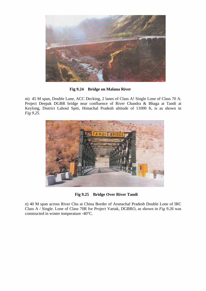
Fig 9.24 Bridge on Malana River m) 45 M span, Double Lane, ACC Decking, 2 lanes of Class A! Single Lone of Class 70 A. Project Deepak DGBR bridge near confluence of River Chandra & Bhaga at Tandi at Keylong, District Lahoul Spiti, Himachal Pradesh altitude of 11000 ft, is as shown in Fig 9.25.
Fig 9.25 Bridge Over River Tandi n) 40 M span across River Chu at China Border of Arunachal Pradesh Double Lone of IRC Class A / Single. Lone of Class 70R for Project Vartak, DGBRO, as shown in Fig 9.26 was constructed in winter temperature -40°C.

Fig 9.26 Bridge for Project Vartak o) 83 M span across River Pala near Kalimpong, IRC Class A Loading with Steel Road Decking to cater for highest seismic zone, as shown in Fig.9.27 was constructed for Darjeeling Gorkha Hill Council.
Fig 9.27 Quadricon Bridge Across River Pala Near Kalimpong p) Number of Piling Platforms, as shown in Fig 9.28, have been designed, fabricated and developed for off-shore Jetties and Ports. The platform eliminates use of expensive floating equipment. As operations are commenced from the share itself in continuing cantilever for heavy piling and the platform moves forward on rollers installed on steel liners. The Piles System allows RCC precast pile caps on deck girders cast, on the approach and carried across the piles by the tail end launching truss at the rear, facilitating completion of approach road simultaneously which is used for movement of all construction, materials eliminating need for floating equipment. The operation of pile driving using heavy driving hammer working at upto 25 m cantilever tip induced 100% reversal of stresses in the Quadricon modular structure resulting in most severe fatigue loading with no adverse effect.

Fig 9.28 Off shore Quadricon Pile Driving Platforms 9.7 Advantages of Quadricon Modular Bridge System (QMBS) • Modular concept obviates design approvals of each individual design once QMBS specifications are established and approved generally by the users. • Longer spans of upto 200 m possible as against 40-50 m in concrete, that too, out standardized moss produced components. Span of 140 m successfully executed in 15 months across fast flowing Chenab River in Jammu in cantilever 100 m Arch Deck Arch across 90 m Deep gorge constructed in cantilever without intermediate support on Indus (an Tibet National Highway) • Lighter weight of superstructure for given load conditions. • Lighter Foundations due to lighter dead load and fewer piers due to longer spans. Consequently minimizes civil works. This affords particular benefit for bridges across waterways where creation of piers/supports is obviated / lessened. • Virtually unlimited fatigue life of the component as against 20-30 years for concrete. Joints successfully fatigue tested for over 2 million cycles what is below the fatigue threshold level. • Manageable Dimensions of modular components enable Hot-Dip Galvanizing of the

entire bridge ensuring a longer service life of at least 75 years even in corrosive environment such as Mumbai. • Ease of transportation and standardized methods of erection requiring minimum skills. • Substantially reduced construction time. This in turn affords significant cost savings in eliminating cost escalations. The overall cost advantages are available particularly for longer spans. • Economy of scale inherent in the modular concept, enabling mass manufacture of standardized components in small scale industries and also in industrially backward areas enjoying fiscal incentives. • Less infrastructure required at site. • Enables 100% Non-destructive Testing of fabricated components making Total Quality Management (TQM) achievable at least cost. Every component can be again proof load tested under simulated loading pattern at sites, just before erection, which eliminates need for load testing of bridge after erection which is cumbersome and expensive. • Small and medium Scale industries can manufacture these components without additional capital investments. This in turn enables fast multiplication of capacity to match the growth of market demand.
9.8 Conclusion Quadricon Prefabricated System facilitates quick construction of a variety of Bridge Superstructures, meeting any span and loading conditions for Highways and Railways. Quadricon Bridge Superstructures are mode out of o few standardized prefabricated components. These are easy to handle Transport and erect by minimum skilled labour. Quadric Bridge Superstructure can be supplied according to the loading and the service life expected by the user/owner which is provided by permutations in Assembly of modular Components. This development and optimization involved international expertise and full scale simulated testing in USA at Lehigh University in the stage of prototype at Bethlehem and repented at The Indian Institute of Technology, Bombay with the final options component. The above testing and evaluating programmed was established to ensure continuous mass production conforming to the established standards and monitoring of the stringent Quality Control involving NDT and DT at various stages.