carbon-fiber subframe design and cae
TRANSCRIPT

Page 1
CARBON-FIBER SUBFRAME DESIGN AND CAE
Nikhil Bolar1, Darren Womack1, Erryn Ashmore1, Armando Perez1, Shiv Pareta1, Vijay Gabbita1, Rudy Schrempf2
Magna International: Cosma International1 / Magna Exteriors2
David Wagner, Xiaoming Chen Ford Motor Company
Abstract
A carbon fiber composite front subframe was designed and manufactured for the Ford Fusion to reduce weight and improve fuel economy. The design process of this compression molded thermoset carbon fiber composite subframe was CAE driven. Finite element analyses were conducted for topology optimization, design iterations and verifications. CAE analyses demonstrated that the carbon fiber composite subframe met performance targets for stiffness, durability and fastener bearing area stress distribution.
The composite utilizes a chopped 50k industrial grade carbon fiber compounded with a modified vinyl ester resin system creating EpicBlendTM CFS-Z SMC. (EpicBlendTM is a trademark of Magna International Inc.) This carbon fiber EpicBlendTM CFS-Z SMC is approximately 50% by weight chopped carbon fiber. The second carbon fiber composite material that is co-molded with the CFS-Z SMC is a pre-preg material that utilizes continuous 0o/90o non crimped fabric, EpicBlendTM CFS-Z 0o/90o NCF. This composite is approximately 56% by weight continuous oriented carbon fiber. Using this multi directional fabric of 300g/m2 with the modified vinyl ester resin system provides a boost in material properties where needed in the subframe. This combination of materials achieves a 7.2 kg (28%) mass reduction over a stamped steel subframe.
The innovative subframe includes six co-molded local EpicBlendTM CFS-Z w/0o/90o NCF patches that are included in the compression molding operation by placing them beneath the SMC charges. Additional innovations include SMC over molded stainless-steel inserts at the body and steering mount locations and carbon fiber SMC energy absorbing front horns. The subframe achieves a dramatic 82% part reduction by replacing the 45 steel parts with two (2) molded parts that incorporate six (6) over molded steel parts. The two moldings, an upper clam shell and a lower close out panel, are joined by adhesive bonding plus structural rivets.
The CAE analyses used material properties derived from flat plaque testing of the composite materials. Multiple design modifications and CAE analyses resulted in a final design that met performance based on the CAE predictions.
Introduction
Light-weighting strategies in the automotive industry [1] is pursued extensively to meet government regulations and fuel efficiency. Automakers have successfully used aluminum as steel replacement in many structures. The balance of cost and weight reduction is always challenging in vehicle engineering. Taking a step further, material alternatives to steel and aluminum are also being investigated. Carbon-fiber reinforced polymers with their low density and high strength to weight ratios can be investigated as alternatives to steel and aluminum in vehicle structures.
Ford Motor Company, Cosma International and Magna Exteriors worked on a development program to investigate the opportunity, engineering and manufacturing challenges in the design of a carbon-fiber intensive subframe for a high-volume production vehicle, the Ford Fusion. The objectives of the project were to design and prototype the lightweight front subframe to meet the

Page 2
performance characteristics namely stiffness, NVH, durability, safety, corrosion, vehicle assembly feasibility similar to current production steel subframe.
Product Information
The current production subframe for the Ford Fusion comprises of several steel stamped parts welded together to form a perimeter design. An image of the same is shown in Figure 1. The structure weighs 26.1 kg.
Figure 1: Steel production subframe labeled with its attachment points
The structure is mounted to the vehicle body at four locations (body mounts, BM in figure 1) via rubber isolators to dampen the vibrations. The attachment points on this structure are listed in Table I and corresponds to the labels in Figure1.
Subframe attachment points
1 Front lower control arm
Front LHS/RHS
2 Rear LHS/RHS
3 Steering gear unit LHS/RHS
4 Stabilizer bar LHS/RHS
5 Engine roll restrictor Center
6 Exhaust hanger LHS/RHS
Table I: List of subframe attachment points
The front lower control arm has two attachment points and the loads are transferred via the ride and handling bushing units. Due to the symmetry of the suspension system there are left-hand and right-hand connections at all the points except the singular engine roll restrictor. The stabilizer bar also has compliance via a bushing and has one attachment point on either side of

Page 3
the vehicle. The steering gear unit has a bolted attachment on each side.
The product requirements comprise of
• Structural performance attributes including stiffness, durability, strength, crash and bolt torque loads
• Environmental and thermal requirements
• Dimensional and assembly requirements
Manufacturing Process and Materials Investigations
Based on the target application of the subframe and their inherent performance requirements, various composite material were considered. Primarily the matrix can be separated into two basic groups, thermoplastic and thermoset materials. These both have a wide range of automotive applications from exterior and interior panels to housings for powertrain components. The key performance driver for the ultimate material selection was the thermal performance under operating conditions.
Thermosets generally have a high glass transition temperature and perform well in a wide range of environmental conditions. These materials considered for application included High Pressure Resin Transfer Molding (HP-RTM) and Sheet Molding Compound (SMC). HP-RTM with a preform is a complex process driving higher cycle times and costs as compared to SMC compression molding process. SMC offered the best combination of mechanical properties, environmental performance and cost effectiveness while being well suited for high volume applications due to a relative lower cycle-time. SMC material is compounded with chopped carbon-fiber within a thermoset resin matrix and is placed in an open mold and cured under heat and pressure in a compression molding process.
An additional unique capability of the SMC process is the ability to process both random chopped fiber as well as continuous directional fibers (0/90 laminate) through the same compounding line. This aspect of the process allowed for a highly tailored solution for the part performance through reinforcing continuous fibers to be co-molded with the short-fiber system with the same resin base.
The SMC compression molding process begins with delivery of the materials to the mold. SMC and uni-directional material charges are pre-cut in an offline process based on the part weight and location of the necessary reinforcement with the laminates. Figure 2 shows a schematic of the process where the charges are placed in a heated mold either by manual or robotic placement depending on the program volumes. Upon placing the charge, the molding cycle begins with the closing of the molds which results in a very high pressure on the material. The heat of the mold and shearing of the material causes the material to flow and fill the die geometry. With the reaction being completed in the resin system the mold is opened and the part is removed and placed on a cooling fixture to handling temperatures and de-flashed.

Page 4
Figure 2: Schematic of the compression molding process
The manufacturing or molding feasibility was based on best practices, process guidelines and cycle-time investigations. With mold flow simulation capability and material characterization not currently fully developed, the components were designed by these guidelines set in collaboration with the manufacturing team. These drove the thickness range and part features. However, where in certain design critical zones these limits could exceed using minor process modifications.
With respect to the assembly of two molded components via an adhesive, the primary bonding area was required to be on a horizontal plane to enable the stability of the adhesive against any wipe and drip. This zone needed a two-sided access to cure in a bonding station.
Material system: Chopped carbon-fiber
During the molding process, the resin and fiber material system flows through the mold cavity resulting in fiber reorientation and possibly some resin rich areas. These lead to the anisotropy of the material thus requiring a robust flow simulation and material characterization models. Due to the development nature of the current project and flow simulation still being developed, material information was extracted from tested coupons on a flat plaque at different orientations. Although not fully representative, a conservative isotropic value was used on the upper composite and stress levels were monitored at critical areas. The mostly flat lower close-out molded component was also evaluated assuming isotropic behavior but with properties at the plaque level.
Material system: UD laminate carbon-fiber (continuous fiber)
The precut laminates were positioned in the die with features in the mold to prevent any collapse of the patch during the molding process. Draping simulation was carried out to understand any large deviations of the laminae and to prevent any tear. With the positions of the laminate being unaffected, anisotropic material properties were used based on the physical testing of the coupons obtained from flat plaques. The coupons were excised at different angles with the same orientation as in the subframe to determine the individual lamina parameters. Special plaques were also developed with all the laminae in a single orientation to establish and verify the parameters.
Both discontinuous and continuous fiber was tested at different temperatures to extract the required material parameters to be help aid the numerical simulations. Table-II gives an overview

Page 5
of the fiber-matrix material properties.
EpicBlend TM CFS-Z Composite Mechanical Properties
Density (g/cm3)
Modulus (GPa)
Specific Modulus (1000 kN-m/kg)
Tensile Strength (MPa)
Specific Strength (kN-m / kg)
CFS-Z SMC 50 wt% CF
1.41 30 21.3 215 152
CFS-Z 0o/90o NCF 56 wt% CF
1.46 50 32.2 660 452
HSLA Steel 7.87 207 26.3 500 63.5
Table II: Carbon Fiber Thermoset Mechanical Properties with reference HSLA Steel
Carbon-fiber composite front subframe
The lightweight perimeter subframe for the Ford Fusion comprises mainly of two compression molded thermoset carbon-fiber composite parts along with multiple steel based over-molded sleeves, washers and rivets. The thermoset composite comprises of a chopped 50k industrial grade carbon fiber with an altered vinyl ester resin system and compounded creating EpicBlendTM CFS-Z SMC. This carbon fiber SMC is approximately 50% by weight chopped carbon fiber. The second carbon fiber composite material that is co-molded with the CFS-Z SMC is a pre-preg material that utilizes continuous fiber lamina oriented at 0o and 90o. Using this multi-oriented laminate of 300g/m2 with a similar matrix system results in an increase in properties in critical areas; predominantly in the clevis attachments of this subframe.
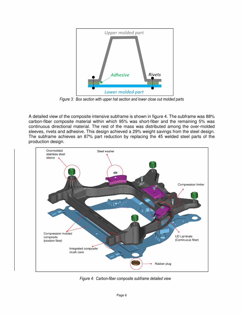
The structure employs a box section concept formed from the two molded components as shown in figure 3. The upper molded component is a hat section molded part flanged along the periphery to enable the joining. There are a significant number of ribbed features within the section to provide internal reinforcement and stiffen the structure. The lower is predominantly flat with ribs at the clevis attachments.
Although adhesive joints are currently used in certain panels and other similar automotive structures, it was identified as a high-risk item in the composite subframe due to the high road loads and temperature/environment conditions. The two molded composite parts are riveted and bonded via stainless steel rivets and a polyurethane based adhesive along the flange. A conservative pitch of 75mm was used to facilitate the rivets.
Page 6
Figure 3: Box section with upper hat section and lower close out molded parts
A detailed view of the composite intensive subframe is shown in figure 4. The subframe was 88% carbon-fiber composite material within which 95% was short-fiber and the remaining 5% was continuous directional material. The rest of the mass was distributed among the over-molded sleeves, rivets and adhesive. This design achieved a 29% weight savings from the steel design. The subframe achieves an 87% part reduction by replacing the 45 welded steel parts of the production design.
Figure 4: Carbon-fiber composite subframe detailed view

Page 7
The six UD laminate patches (continuous fiber) are strategically located at the clevis attachment on the upper and lower molded parts. Other innovative features include the over-molded stainless sleeves at the body mount and steering attachment locations. The crush horns or the front crush cans are integrated into the molded parts as well. An image of the prototyped subframe is shown in Figure 5.
This subframe was also machined at the attachment zones to meet the dimensional requirements and tolerances. CMM data was established and accepted for the prototyped parts and the vehicle assembly was also verified. As a part of the standard automotive process, detailed engineering drawings were developed at component and assembly levels specifying the requirements at all critical and non-critical zones. The subframe showed a good dimensional stability at component and vehicle levels.
Figure 5: Carbon-fiber composite subframe prototype
The four over-molded stainless-steel sleeves at the body mount locations were cast with features on the outer surface to enable a locking mechanism with the molded composite. The sleeves aid the design by assisting the bushing push-in and push-out requirements, as an isolating interface to the aluminum outer can on the bushing and provide rigidity to the suspension load transfer from the structure to the mount. Figure 6 shows the region of the over molded sleeve at the front body mount with stiffening ribs along the vertical post. A similar over-molded sleeve is used in the steering attachment location as a compression limiter.
The design also included steel washers with a specific hardness and coating requirement at attachment locations. This aided in the isolation of the bolts with the exposed fibers on the subframe to prevent galvanic corrosion. They were also designed by altering the thickness and

Page 8
diameter for load distribution over an area using the theoretical bolt pressure cone from the applied torque. A collar feature was present in the washers to fit in the machined holes of the composite subframe.
Figure 6: Over-molded body mount stainless steel sleeve
Structural performance and CAE results
The structural performance of the carbon-fiber composite designs is based on a combination of design targets and the current production steel design. The three main sub-system level attributes are evaluated with static stiffness, durability and strength load-cases.
Stiffness Analysis / Topology Optimization
The static stiffness is evaluated by applying unit loads at all attachment points (Table I) of the subframe. Using Hooke’s law, k= F/d where F is the applied load (N) at the attachment point along a vector, d is the resulting displacement (mm) along that direction, the stiffness k (N/mm) along the direction of the vector is evaluated.
The design space of the subframe was developed based on the static and dynamic clearances of the adjacent systems. Topology optimization [8] was first carried out on the design space with the stiffness targets translated to displacement constraints corresponding to applied unit loads. The analyses were considered with and without several manufacturing constraints to understand load path of the resulting structure. A snapshot of the design space and topology results with draw constraints are visualized in figure 7.

Page 9
Figure 7: Front subframe design space and topology optimization results
The topology results cannot be directly translated to a feasible final design, but it does give a general picture of the main load-paths for reinforcements and shear plane for critical areas. The optimization was carried out using isotropic material properties for the short fiber composite and the designs were drafted for manufacturing and assembly feasibility. Due to the thickness limitations driven by the cycle-time requirements, laminates (NCF) were introduced at the clevis attachments to locally reinforce the structure without which achieving the targets posed a challenge. Sixteen layers of orthogonal unidirectional laminae were therefore co-molded with the short-fiber material system.
Durability: Global endurance design loads
The structure was evaluated for component level durability loads (also known as the endurance loads) which is equivalent to the full vehicle 150,000 miles as per the Ford corporate standard. The durability loads include several events like cornering, jounce/rebound, stab-bar/roll, max-tie-rod, etc. to reflect different road load events. Each loading event has an associated load at the attachment points resolved in their respective translational and rotational components. The events also have an associated repeat cycle establishing the number of times the vehicle goes through the loading cycle. Using DesignLife [10], the fatigue damage is determined per event from the evaluated static stresses and its corresponding repeat cycle. The total fatigue life of the structure is determined from the inverse of the summation of the accumulated damage from all events.
Prior to fatigue material testing the design was analyzed for the endurance loads with a factor of the material yield (x% of σy). Maximum damage driving static loading condition was extracted by time-slicing the durability event profile. This enabled a quick check to review the stress values on the structure and modify the designs.
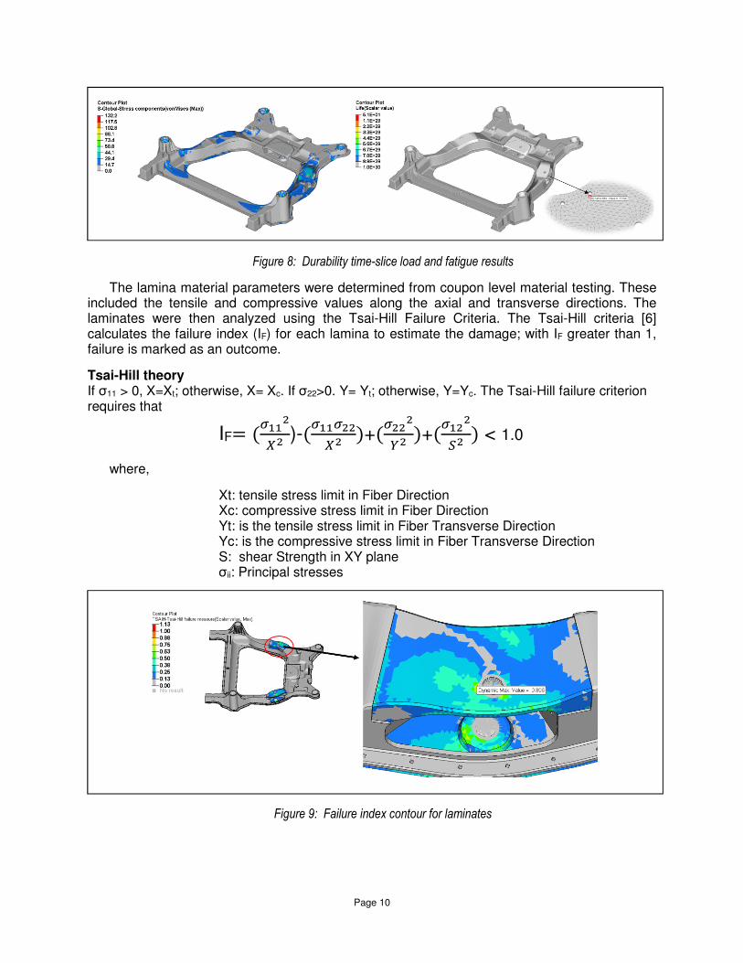
Once the coupon level fatigue testing was completed, a stress-life curve was generated to enable a fatigue analysis taking account into all the durability loading events and estimate the accumulated damage. This approach was the decision-making analysis for fatigue assessment. Figure 8 shows the time-sliced static results (stress values) for an intermediate design iteration and the fatigue results (life) for one of the final design iterations.
Page 10
Figure 8: Durability time-slice load and fatigue results
The lamina material parameters were determined from coupon level material testing. These included the tensile and compressive values along the axial and transverse directions. The laminates were then analyzed using the Tsai-Hill Failure Criteria. The Tsai-Hill criteria [6] calculates the failure index (IF) for each lamina to estimate the damage; with IF greater than 1, failure is marked as an outcome.
Tsai-Hill theory If σ11 > 0, X=Xt; otherwise, X= Xc. If σ22>0. Y= Yt; otherwise, Y=Yc. The Tsai-Hill failure criterion requires that
IF= (���
�
��)-(
������
��)+(
����
��)+(
����
�) < 1.0
where,
Xt: tensile stress limit in Fiber Direction Xc: compressive stress limit in Fiber Direction Yt: is the tensile stress limit in Fiber Transverse Direction Yc: is the compressive stress limit in Fiber Transverse Direction S: shear Strength in XY plane σii: Principal stresses
Figure 9: Failure index contour for laminates

Page 11
Permanent-set analysis: Global static strength
The structure was also assessed for strength via the permanent-set loads also known as the global strength loads. These loads are not repetitive in nature but can be reviewed as an extreme occurrence to ensure the structure remains intact with limited displacement and stress/strain levels with no separation from the connected systems. The global strength load-case is evaluated in two increasing load levels to ensure structure integrity. Typically, the simulation is carried out in a non-linear load case with non-linear material properties. Since the composite material exhibits very limited plasticity in the post yield zone, the target criteria were adjusted to ensure the stress levels are below the yield limit. Figure 10 shows the results for the chopped-fiber material system where the stresses were well below yield limit. The laminates showed a failure index of over 1.0 in certain regions (figure 11). With all laminate parameters not fully developed and with conservative values, the joint was to be evaluated during the prototype. Physical Clamping/Torque tests showed no failure in this location.
Figure 10: Stress distribution under permanent set load case: SMC/Short fiber
Figure 11: Failure index distribution under permanent set load case: Laminates
Apart from these main sub-system level analyses, the subframe was also assessed for safety/crash simulation and bolt torque analysis at the attachment points. Although safety/crash simulation on a sub-system level is carried out to compare results with the baseline steel design,

Page 12
an evaluation on a full vehicle level ensures it meets the structural performance and system level dynamics. In the full vehicle simulation, the vehicle with a velocity of 36 mph impacts a rigid flat frontal barrier. The crash strategy is to absorb certain percentage of energy via the crush horns prior to the dynamics. The approach on the sub-system level analysis is carried out with a quasi-static analysis using LSDyna [9] with defined failure in the material system. Apart from the longitudinal translation on the front body mount, the subframe is constrained in all degrees of freedom at the body-mount locations, a rigid barrier is prescribed to translate along the vehicle’s longitudinal axis as shown in figure 12.
Figure 12: Quasi-static analysis set-up: BM Front:
The intended system dynamics following the initial crush at the front horns includes the separation mode at the rear body mount locations. Figure 13 shows the results for the quasi-static subframe at an instance showing the failure progression where the front horns have absorbed certain initial energy and separation is ensued at the rear body mounts.
Figure 13: Quasi-static results

Page 13
Clamping analysis for bolt torque loads
Clamping simulation or bolt torque analysis was simulated at the all attachment points to ensure structural integrity within the specified torque limits. This is critical to the design of the structure in the local regions of all bolt attachment points; e.g. clevises (control arm front and engine roll restrictor) where a minimized initial gap is designed to account for the bushing inner metal sleeve tolerances to ensure assembly and non-clevis joints like the steering and the stabilizer bar/ rear control arm attachments where the structure is evaluated under column loads as a result of the applied torque.
The analysis was conducted using Abaqus [7], a finite element solution system where all interfaces at the joint under review were modeled with contact elements. The deformation and stresses/strains were observed, and design changes were implemented accordingly. Based on the assembly and part variations, the tolerances were considered during the development and analysis of the finite element model. Typically, during vehicle assembly the pre-designed gap allows the sub-systems to be assembled easily. The initial bolt torque load is used to close the gap before enabling a clamped joint. Clamping efficiency of a particular joint is then determined by the percentage of the remaining torque. The stress levels on the structure are also evaluated to ensure it is below the design limits. For a non-clevis joint where there are no intended gaps, a column feature like a boss provides the structure rigidity and the stress levels are monitored during the clamping simulation.
Figure 13 shows the model setup for the front control arm clevis joint. During the bolt torque process, the composite surfaces are pulled towards the inner-metal from the control arm busing closing the design gap and the torque load continues to rise till it reaches the specified limit. The clamping efficiency, stresses in the composites (short fiber and continuous fiber/laminates) are evaluated to help aid the design.

Page 14
Figure 14: Front LCA model set up
Figure 15: Laminates Failure Index under clamping load
Figure 16: short fiber composite stresses under clamping load
Figure 17: short fiber composite stresses under clamping load
The stress results for the laminate and the short fiber from the simulation can be visualized in figures 15 through 17. Although high stresses were observed in the short fiber composite system, they were localized and/or adjacent to a rigid element. The physical tests showed no failure in these locations.
Figure 18 shows the clamping contour and load plot. The plot is used to determine the load at gap closure from which the joint clamping efficiency is evaluated.
Interface 9 normal force = 109330 N
Clamping efficiency, e = (Normal Force / Total clamp-force) x 100
e = (20670/130000) x 100 = 84.1%

Page 15
Figure 18: Clamping efficiency of the clevis joint
In a similar manner, the rest of the attachments were analyzed. The non-clevis joints were analyzed for stress levels. Prototypes underwent torque testing at the Ford test lab and the clevis attachments passed the tests without any failure. The steering attachment also passed the torque test but at a slightly lower torque level and was used as the new redefined limit for that attachment. With further investigation lower load level was estimated to be from an assembly induced minor gap at the neighboring attachment point which is expected to be resolved with minimal changes.
Other Targets
The environmental performance targets set for this program were the same as the production design. The subframe with the composite material was expected to survive in the under-hood and under-body environmental conditions at various extreme temperatures and interaction with auto-fluids such as transmission ATF, petroleum, motor-oil, brake fluid, anti-freeze dot-4, 38% sulphuric acid and road salts. The material was selected based on some prior knowledge and engineering judgement to meet the specs. Further information on corrosion strategies and test results can be reviewed in the publication [3] of SPE’s ACCE-2019.
The understanding of the thermal environment around a subframe is vital in the design of the composite subframes. The elevated temperatures and the ambient conditions of the region may affect the properties of the composite material system. Hence material testing of Magna’s proprietary EpicBlendTM CFS-Z was carried out at different temperatures to understand its behavior.
The dimensional requirements were carried over from the production design in order to enable a similar appropriate assembly with the body, steering and suspension components. These include the positions and tolerance requirements of the body mounts and clevis/bolted attachments. Dimensional analysis using a VSA software was used to understand the resulting assembly variations based on inputs from process capabilities.
Prototype Testing: Component and vehicle level
The details on the component and vehicle level testing is published in the current SPE’s ACCE-2019 series Chen [2].

Page 16
Business case and cost estimates
A production and business study on the subframe are published in the current SPE’s ACCE-2019 series Krull [4].
Summary and Next steps
The carbon fiber intensive subframe project exhibits a lot of potential in automotive engineering especially in structural applications. The development work involved a significant amount of engineering discussions and thought process. The project successfully demonstrated the product manufacturing feasibility with advanced solutions like over-molding and co-molding along with the design features in a compression molding process while meeting the intended large volume production capability. CAE simulation aided by material testing and engineering assumptions helped the design to be successful in almost all the physical tests.
This project also broadens the light-weighting capability of composite materials in chassis structures. However, there is a need to understand material characterization and properties especially in the areas of molding simulation and predictive properties to achieve correlation and optimize the engineering process and product in the future.
Acknowledgements
The authors acknowledge and gratefully thank our colleagues at Magna Exteriors, Cosma International, Magna Composites Centre of Excellence, Ford Research & Advanced Engineering, Ford Chassis Engineering and many others for contributing to the exciting project. In total over 100 researchers, engineers and scientists helped design, analyze, build, test and evaluate the carbon fiber composite front subframe. The numerous suppliers included, among others, Zoltek, a division of the Toray Group, Tycos Tool and Die (Magna), CTS Composites Group, Stanley/Crawford Products, Barron Industries, Ashland and others. Success was achieved by collaborating and leveraging the diverse areas of expertise exhibited by all team members.
References
1. Wagner, Chen, Uicker, Weiler, Swikoski, Bolar, “Ford Lightweight Subframe Research and Development”, Lightweighting World, July-August 2017.
2. Chen, Wagner, Uicker, Bolar, “Carbon Fiber subframe development – Fatigue and strength CAE and Test results”, Automotive Composites Conference & Exhibition, 2019
3. Chen, Hosking, Anderson, Wagner, Bolar, “Carbon Fiber subframe development – Corrosion and Mitigation Strategies and Test Results”, Automotive Composites Conference & Exhibition, 2019
4. Krull, Ingram, Chen, Dahl, Wagner, “Carbon Fiber subframe Manufacturing process and cost estimates”, Automotive Composites Conference & Exhibition, 2019
5. Nettles, “Basic mechanics of laminated composite plates”, NASA reference publication 1351.
6. Simulia, Abaqus Analysis User’s Guide, Version 2017
7. MSC.Nastran Reference Manual- Layered Composite Material Analysis, 2004
8. Altair Engineering Inc., “Optistruct User’s Guide”, 2017
9. LS-DYNA Keyword User’s Manual, R9, Livermore Software Technology Corporation (LSTC), 2016
10. nCode DesignLife Theory Guide, Version 13.1, 2017