car park jet fan
TRANSCRIPT

7/15/2019 Car Park Jet Fan
http://slidepdf.com/reader/full/car-park-jet-fan 1/14
1
Kruger Induced Jet Fan Ventilation Systems
C ar P ar k V en t i l a t i on S y s t em
7/15/2019 Car Park Jet Fan
http://slidepdf.com/reader/full/car-park-jet-fan 2/14
2
Kruger Induced Jet Fan
Why our model outperforms products from our competitors
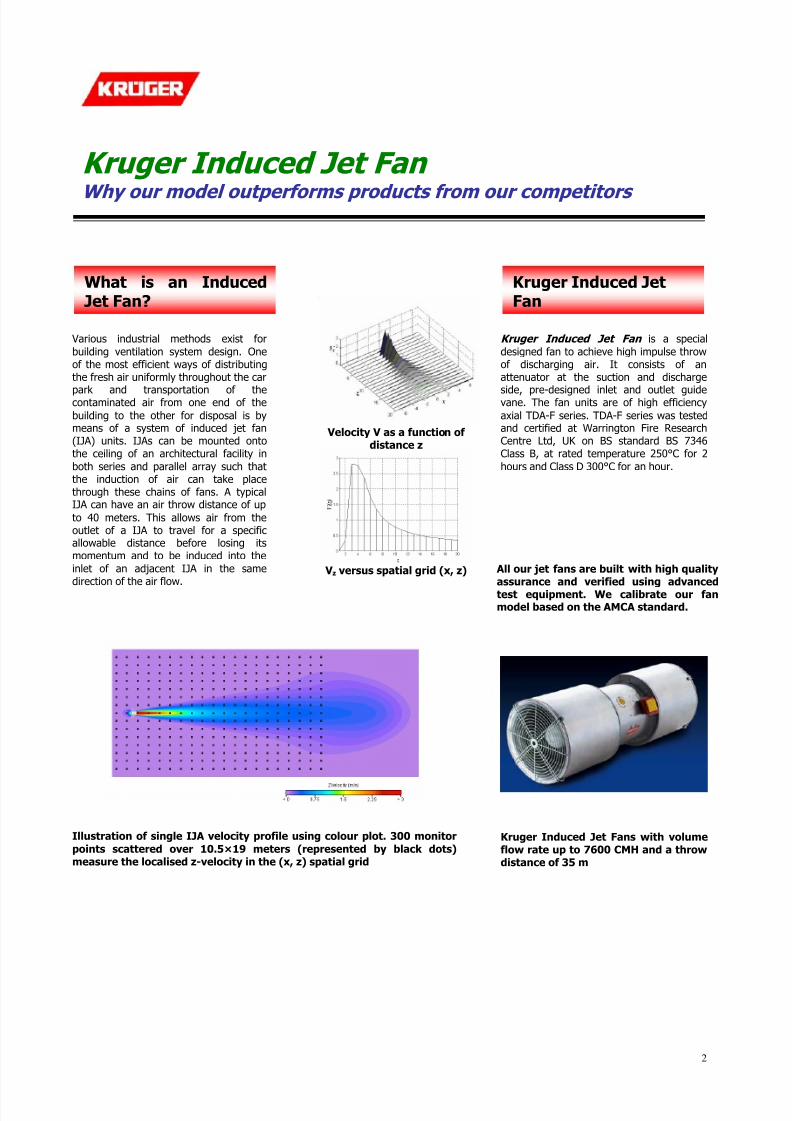
Velocity V as a function of distance z
V z versus spatial grid (x, z)
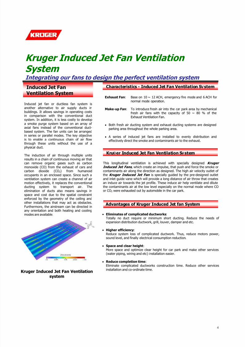
Kruger Induced Jet Fan is a special
designed fan to achieve high impulse throwof discharging air. It consists of anattenuator at the suction and discharge
side, pre-designed inlet and outlet guidevane. The fan units are of high efficiency
axial TDA-F series. TDA-F series was testedand certified at Warrington Fire ResearchCentre Ltd, UK on BS standard BS 7346Class B, at rated temperature 250°C for 2
hours and Class D 300°C for an hour.
Various industrial methods exist for
building ventilation system design. Oneof the most efficient ways of distributingthe fresh air uniformly throughout the car
park and transportation of thecontaminated air from one end of the
building to the other for disposal is bymeans of a system of induced jet fan(IJA) units. IJAs can be mounted ontothe ceiling of an architectural facility in
both series and parallel array such thatthe induction of air can take placethrough these chains of fans. A typicalIJA can have an air throw distance of up
to 40 meters. This allows air from theoutlet of a IJA to travel for a specificallowable distance before losing itsmomentum and to be induced into the
inlet of an adjacent IJA in the samedirection of the air flow.
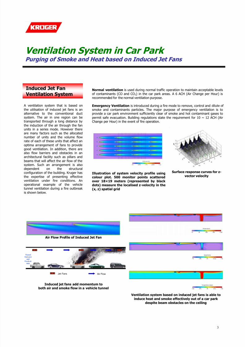
Kruger Induced Jet Fans with volumeflow rate up to 7600 CMH and a throwdistance of 35 m
Illustration of single IJA velocity profile using colour plot. 300 monitor
points scattered over 10.5×19 meters (represented by black dots)measure the localised z-velocity in the (x, z) spatial grid
What is an InducedJet Fan?
Kruger Induced JetFan
All our jet fans are built with high qualityassurance and verified using advancedtest equipment. We calibrate our fanmodel based on the AMCA standard.
7/15/2019 Car Park Jet Fan
http://slidepdf.com/reader/full/car-park-jet-fan 3/14
3
Ventilation System in Car Park
Purging of Smoke and Heat based on Induced Jet Fans
Normal ventilation is used during normal traffic operation to maintain acceptable levelsof contaminants (CO and CO2) in the car park areas. A 6 ACH (Air Change per Hour) isrecommended for the normal ventilation purpose.
Emergency Ventilation is introduced during a fire mode to remove, control and dilute of smoke and contaminants particles. The major purpose of emergency ventilation is toprovide a car park environment sufficiently clear of smoke and hot contaminant gases to
permit safe evacuation. Building regulations state the requirement for 10 ~ 12 ACH (Air
Change per Hour) in the event of fire operation.
Illustration of system velocity profile usingcolour plot. 500 monitor points scattered
over 18×19 meters (represented by black dots) measure the localised z-velocity in the
(x, z) spatial grid
Surface response curves for z-
vector velocity
Air Flow Profile of Induced Jet Fan
Tunnel
Entrance
and
Fresh air
inlet
Jet Fans Air Flow
Induced jet fans add momentum toboth air and smoke flow in a vehicle tunnel
Ventilation system based on induced jet fans is able to
induce heat and smoke effectively out of a car park
despite beam obstacles on the ceiling
Induced Jet Fan Ventilation System
A ventilation system that is based on
the utilisation of induced jet fans is analternative to the conventional ductsystem. The air in one region can be
transported through a long distance bythe induction of the air through the fanunits in a series mode. However thereare many factors such as the allocatednumber of units and the volume flowrate of each of these units that affect an
optima arrangement of fans to providegood ventilation. In addition, there arealso flow barriers and obstacles in anarchitectural facility such as pillars and
beams that will affect the air flow of thesystem. Such an arrangement is alsodependent on the structuralconfiguration of the building. Kruger has
the expertise of presenting effective
ventilation under fire conditions. Anoperational example of the vehicletunnel ventilation during a fire outbreak
is shown below.
7/15/2019 Car Park Jet Fan
http://slidepdf.com/reader/full/car-park-jet-fan 4/14
4
Kruger Induced Jet Fan Ventilation System Integrating our fans to design the perfect ventilation system
Advantages of Kruger Induced Jet fan System
Kru er Induced Jet Fan Ventilation S stem
Induced Jet Fan Ventilation System
Characteristics - Induced Jet Fan Ventilation S stem
This longitudinal ventilation is achieved with specially designed Kruger Induced Jet Fans , which create an impulse, that push and force the smoke orcontaminants air along the direction as designed. The high air velocity outlet of the Kruger Induced Jet Fan is specially guided by the pre-designed outlet
and inlet guide vane which will provide a long distance of air throw that creates
an induce air towards the jet profile. These induce air help ventilate and dilutethe contaminants air at the low level especially on the normal mode where COor CO2 were exhausted out by automobile in the car park.
Induced jet fan or ductless fan system isanother alternative to air supply ducts inbuildings. It allows savings in operating costsin comparison with the conventional ductsystem. In addition, it is less costly to develop
a smoke purge system based on an array of axial fans instead of the conventional duct-based system. The fan units can be arrangedin series or parallel modes. The key objective
is to enable a continuous chain of air flowthrough these units without the use of aphysical duct.
The induction of air through multiple unitsresults in a chain of continuous moving air thatcan remove organic gases such as carbonmonoxide (CO) from the exhaust of cars andcarbon dioxide (CO2) from humanoid
occupants in an enclosed space. Since such aventilation system can create a channel of air
motion effectively, it replaces the conventionalducting system to transport air. The
elimination of ducts also means savings inspace and cost due to the spatial constraintenforced by the geometry of the ceiling andother installations that may act as obstacles.
Furthermore, the airstream can be directed inany orientation and both heating and coolingmodes are available. Eliminates of complicated ductworks:
Totally no duct require or minimum short ducting. Reduce the needs of expansion distribution ductwork, grill, louver, damper and etc.
Higher efficiency:Reduce system loss of complicated ductwork. Thus, reduce motors power,sound level, and finally electrical consumption reduction.
Space and clear height:More space and optimize clear height for car park and make other services(water piping, wiring and etc) installation easier.
Reduce completion time:Eliminate complicated ductworks construction time. Reduce other services
installation and co-ordinate time.
Exhaust Fan: Base on 10 ~ 12 ACH, emergency fire mode and 6 ACH for
normal mode operation.
Make-up Fan: To introduce fresh air into the car park area by mechanicalfresh air fans with the capacity of 50 ~ 80 % of the
Exhaust Ventilation Fan.
Both fresh air ducting system and exhaust ducting systems are designedparking area throughout the whole parking area.
A series of induced jet fans are installed to evenly distribution andeffectively direct the smoke and contaminants air to the exhaust.
Kruger Induced Jet Fan Ventilationsystem

7/15/2019 Car Park Jet Fan
http://slidepdf.com/reader/full/car-park-jet-fan 5/14
5
Smoke Control Using Induced Jet Fans
Looking into the modern smoke control system
Kruger Electronic-based Smoke Control System
Measured Signal
Measured Signal
Measured Signal
Smoke, Heat
and CO Probes
Exhaust Fans
Heat
Sensors
ch2
ch5
ch4
ch5 ch4
ch3
ch2
ch1
ch3 ch2
Smoke Control System
Supply Fan Controller
Air Jet Fan Controller
Exhaust Fan Controller
CO Indicator
Smoke Indicator
Threshold Functions
Temperature Indicator
Power Supply
+
-
ch0ch1ch2ch3ch4ch5ch6ch7
ch0ch1ch2ch3ch4ch5ch6ch7
ch0ch1ch2ch3ch4ch5ch6ch7
+ -
Supply Fan
Controller
Channels
Control SignalFrequency Inverter
SmokeSensors
CO
Sensors
Activation
Measured Signal
Measured Signal
Measured Signal
Smoke, Heat
and CO Probes
Kruger
Jet Fans
Heat
Sensors
CO Indicator
Smoke Indicator
Temperature Indicator
Control SignalFrequency Inverter
SmokeSensors
CO
Sensors
Activation
Measured Signal
Measured Signal
Measured Signal
Smoke, Heatand CO Probes
Supply Fans
Heat
Sensors
CO Indicator
Smoke Indicator
Temperature Indicator
Control SignalFrequency Inverter
Smoke
Sensors
CO
Sensors
Activation
Air Jet FanController
Channels
Activated
Jet FanAir Flow Heat, Smoke
& CO sensorsFire
Emergency region that requires immediate
purge of smoke and heat
Activated
Exhaust
Fan
Activated
Supply
Fan
Legend
Shown above is a smoke control electronic system for acar park that is installed with induced air jet fans, as
well as exhaust and supply fans. It is built with heat,smoke and CO sensors that will detect the presence of high temperature and smoke generation. The fanswithin the region of the fire will be activated to remove
the undesirable contaminants at an increased rate.
Emergency smoke and heat purge by induced jet fan ventilation system in a car park
On the left: When the sensors detect the presence of high temperature and smoke concentration, the fansassigned to the segment, which the controller identifies
as the fire region is activated. Only activated fans withinthe vicinity of the fire takes part in the purging process.
Kruger Smoke Control System
Kruger smoke control system is the state-of-the-art
technology that is developed by our very own team of engineers. As a result, it is of low initial cost and we ensurehigh quality and reliable data acquisition from sensor
probes and accurate control based on low levelprogrammed algorithms.
The control system typically consists of smoke, heat andCO probes that are strategically positioned at variouslocations in a car park. These probes detect temperature
and count of smoke particles and send the signal to acontrol system. If the system identifies an abnormal rise of heat and smoke concentration within a short period of timethat signifies the possibility of a fire, an alarm will be
activated. When these concentrations reach a level that isabove the threshold set by the system, the supply andexhaust fans will be increased to a higher operation by thecontroller. The induced jet fans will also have a higher
volume flow rate to purge the smoke and heat at a faster
rate so that visibility can be reduced to an acceptable levelfor humans to f ind their escape routes.
Sensors are evenly distributed in a car park and the systemis able to detect the location where there is a fire outbreak.If the fire is localised in a space, only the fans that arewithin the encapsulation perimeter from the centre of thefire are activated.

7/15/2019 Car Park Jet Fan
http://slidepdf.com/reader/full/car-park-jet-fan 6/14
6
An Effective Ventilation System Our system design methodology
Computational model showing carpark floor layout
Computational models used in the design of theventilation system that is based on KrugerInduced Jet Fans in the Bandar Utama Project,
Malaysia
Architecturalsurvey of car
park
Identification of
flowrequirements
and obstacles in
enclosure
Placement offans and design
of air circuit
Adjusting
volume flow rateof induced jet
fans and supply
exhaust fans
Verify
effectiveness ofventilation
system design
using CFD
Deliver CFDoutputs and
graphs
Systematic approach for the design of Kruger Induced Jet Fan Ventilation System in a car park
ComputationalFluid Dynamics
All ventilation systems designed
for car parks are verified atKruger using Computational FluidDynamics (CFD) software.
Simulation models of the building(or car park) are built, tested andanalysed. The details of thedevelopment and validation of aventilation model using inducedet fans is given. The model has
been extensively validated usingthe test data from CFDsimulation. The effectiveness of ventilation is determined by the
degree of stagnant air regionsduring normal operation mode of the fan units and the magnitudeof gas contaminants and heat
resulting from a simulated fire
when the units are activated atfull power.
DesignMethodology
Systematic approach that consists of building survey, followed by theidentification of air sources,
pressure differences and resistancesto flow is implemented at Kruger.
Once an efficient air circuit isdesigned, the pressure differencesat various locations are modified toachieve the desired flow rates at
different zones. The pressuredifferences or energy potentialdifferences flows over the resistorssuch as obstacles, pillars, ceiling
beams, walls and staircases in thecar park. Once we have confirmedthat an effective air current isflowing, the next step will be to varythe potential difference and
resistance to create the desiredcurrent. This means that we canmodify the total number or volumeflow rates of the fans that control
the total volume flow rate forsupply, exhaust or migration of airfrom one point to another.
Design of an Effective Ventilation System

7/15/2019 Car Park Jet Fan
http://slidepdf.com/reader/full/car-park-jet-fan 7/14
7
Computational Fluid Dynamics
A powerful tool in our organisation
Air jets from fans at fan height level Smoke Concentration Level (ppm)
Temperature Level (deg Celsius) Air Speed Level (m/s)
Computational Fluid Analysis
Computational Fluid Dynamics (CFD) analysis has beenundertaken to provide an effective method of determiningthe optimum placement of induce jet fan units in an
enclosure, so as to achieve the best ventilation. The
examination of the air circuitry is important in ensuringthat the distribution of air and its movement properties aresufficient to provide the enclosure for both general and
emergency ventilation cases. In a car park, the generalventilation of carbon monoxide (CO) and carbon dioxide(CO2) is achieved by the daily and periodic operation of theinduce jet fans. During a fire outbreak when smoke is
produced at high rates, all the fans are activated at fullpower to push the dangerous contaminants out of thebuilding. Therefore, it is vital that induced jet fans arepositioned strategically throughout the car park to maintain
a distribution of air that covers sufficient areas to removepotential stagnant air regions known as ‘dead spots’ andwhich moves fast enough to transport any contaminantsproduced within the enclosure.
CFD has been used to illustrate the effectiveness of positioning fans based on our specialist’ s proposedconfiguration. The degree of ventilation is analysedusing the speed, smoke concentration, and
temperature contour plots of the ventilation systemthat is operating at normal and emergency modesfrom the front, plan and side views
A fire is typically simulated within the facility and the fans areactivated to the full power mode. The volume flow rates of each fan is doubled and smoke concentration plots areprepared for the fire situation. For both the normal andemergency operational modes, the CFD model of a ventilation
system is sometimes verified using experimental results.Useful deduction on the performance of the system is made.Steady and transient state solutions provide insights on themost effective smoke control using our designed ventilation
system.
Fire simulation in car park from isometricview
CFD simulation outputs enable us to predict thedistribution of smoke and heat from a fire sourceand how air flows through the spatial region inthe car park

7/15/2019 Car Park Jet Fan
http://slidepdf.com/reader/full/car-park-jet-fan 8/14
Induced Jet FAN
IJA Se rie s

7/15/2019 Car Park Jet Fan
http://slidepdf.com/reader/full/car-park-jet-fan 9/14
Induced Jet Fan – IJA Series Fan
• Double flanged casing is produced in mild steel orgalvanised Steel.
• Impeller is made of PPG, PAG or Aluminum withmanually adjustable pitch blades.
• Painting or galvanized finish on all parts.
• Totally enclosed Class ‘F’/’H’ motor with a min.IP54 protection. Motors up to 2.2kW are usuallysupplied on DOL starting, motors 3.0kW and above
are star/delta starting. • Unidirectional or truly-reversible flow direction. Silencer
• Outer casing made of galvanized steel sheet andinner casing made of galvanized steel perforatedsheet.
• Rounded nose to smooth airflow and a tapered tailto reduce the air turbulence and pressure drop.
• Glass fiber as absorption filler material to achieveexcellent acoustic performance.
• Each model is available with 1D/2D silencer asstandard length. Non-standard length to meetspecial performance requirement can be suppliedupon request.
Technical Data
ModelFlow Rate
m3/h
Outlet Velocity
m/s
Installed Power
kW
Phase Hz VoltagedB(A) at
3m
RPM
2250 8.0 0.11 3 50/60 400/380 38/38 1450/1750IJ A 315
4500 16.0 0.75 3 50/60 400/380 54/54 2850/3450
3240 9.1 0.2 3 50/60 400/380 43/42 1450/1750IJ A 355
6480 18.2 1.5 3 50/60 400/380 58/58 2850/3450
4500 10.0 0.6 3 50/60 400/380 44/46 1450/1750IJ A 400
9000 20.0 3.6 3 50/60 400/380 60/62 2850/3450
6000 10.5 0.6 3 50/60 400/380 46/47 1450/1750IJ A 450
12000 21.0 3.6 3 50/60 400/380 62/62 2850/3450
Dimensions
Model A B C L
IJ A 315 315 415 355 1125
IJ A 355 355 455 355 1225
IJ A 400 410 510 450 1394
IJ A 450 460 560 450 1510
Accessor ies
Mounting Feet
Dimensions
Mounting Feet Hanger Model
A B C D H Wt/set (kg) A B Wt/set (kg)
IJ A 315 265 315 25 50 209 2 355 263 2.2
IJ A 355 290 355 25 50 237 2 395 263 2.2
IJ A 400 304 400 25 50 265 2.5 440 263 2.2
IJ A 450 375 450 25 50 288 3 490 288 2.4
Hanger
C
L
Ø B
Ø A
A
B
2° x Ø10
2° x Ø10
A
B
C
D
H
All Dimensions in mm.

7/15/2019 Car Park Jet Fan
http://slidepdf.com/reader/full/car-park-jet-fan 10/14
Induced Jet Fan – IJA Series
Distance from Nozzle (m) 2 4 6 8 10 12 14 16 18 20 22 24
Flow Width d (m) 0.85 1.70 2.55 3.40 4.25 5.10 5.95 6.80 7.65 8.50 9.35 10.20
IJA 315 5.62 3.47 2.42 1.86 1.51 1.27 1.09 0.91 0.73 0.55 0.37 0.25
IJA 355 6.42 4.35 3.05 2.35 1.91 1.61 1.39 1.22 1.09 0.96 0.83 0.70
IJA 400 7.41 5.26 3.72 2.87 2.33 1.97 1.70 1.50 1.34 1.21 1.10 1.01
Center Line Velocity (m/s)
IJA 450 7.82 5.73 4.37 3.36 2.74 2.32 2 1.77 1.58 1.43 1.3 1.2
Distance from Nozzle (m) 26 28 30 32 34 36 38 40 42 44 46 48
Flow Width d (m) 11.05 11.90 12.75 13.60 14.45 15.30 16.15 17.00 17.85 18.70 19.56 20.41
IJA 315 - - - - - - - - - - - -
IJA 355 0.57 0.44 0.24 - - - - - - - - -
IJA 400 0.94 0.84 0.74 0.64 0.54 0.44 0.26 - - - - -
Center Line Velocity (m/s)
IJA 450 1.11 1.03 0.97 0.91 0.85 0.81 0.77 0.67 0.57 0.47 0.37 0.27
IJA 315 IJ A 355 IJ A 400 IJ A 450
d
Tested by Warrington Fire Research which is UK’slargest independent specialist in fire safety testing,consultancy and research.
IJA series were tested in accordance with BS7346 Part2: 1990 and satisfied the performance criteria for ClassB as defined in BS standard.
ClassTemperature
(°C)Duration
(hrs)
A 150 5.0
B 250 2.0
C 300 0.5
D 300 1.0
E 400 2.0
F 600 1.5
G 650 1.0
H 840Achieved in 0.5 hrs(No rated duration)
TESTING

7/15/2019 Car Park Jet Fan
http://slidepdf.com/reader/full/car-park-jet-fan 11/14
IJC 9/7T
Specification
Dimension
850
4 0 0
950798
3 5 0
9881028
Dia 125
Velocity Profile
Distance (m) 1 2 3 4 5 6 7 8 9 10 11 12 13
Velocity (m/s) 10.55 5.85 4.04 3.09 2.50 2.10 1.81 1.59 1.42 1.28 1.17 1.07 0.99
Distance (m) 14 15 16 17 18 19 20 21 22 23 24 25 26
Velocity (m/s) 0.92 0.86 0.81 0.76 0.72 0.68 0.65 0.62 0.59 0.56 0.54 0.52 0.50
Fan Flow Rate (m3/h) 2200 Power (W) 550
Fan Speed (rpm) 1350Power Supply
(V/Ph/Hz)220~240/1/50
Nozzle Diameter (mm) 125 Outlet Velocity 16.6

7/15/2019 Car Park Jet Fan
http://slidepdf.com/reader/full/car-park-jet-fan 12/14
IJC 10-8
Specification
Dimension
5 0 0
9501098
4 0 0
988
1028
4 5 0
Ø127
Ø9
1150
Velocity Profile
Distance (m) 0 2 4 6 8 10 12 14 16 18 20 22 24
Velocity (m/s) 18.70 6.82 3.61 2.46 1.86 1.50 1.25 1.08 0.94 0.84 0.76 0.69 0.63
Fan Flow Rate (m3/h) 2700 Power (W) 550
Fan Speed (rpm) 1300Power Supply
(V/Ph/Hz)230~240/3/60
Nozzle Diameter (mm) 127 Outlet Velocity 18.7

7/15/2019 Car Park Jet Fan
http://slidepdf.com/reader/full/car-park-jet-fan 13/14
IJM 250x2
Specification
Dimension
Velocity Profile (For single fan)
Distance (m) 1 2 3 4 5 6 7 8 9 10 11 12 13
Velocity (m/s) 6.32 4.79 3.42 2.65 2.17 1.83 1.59 1.40 1.25 1.13 1.04 0.95 0.88
Distance (m) 14 15 16 17 18 19 20 21 22 23 24 25 26
Velocity (m/s) 0.82 0.77 0.72 0.68 0.64 0.61 0.58 0.55 0.53 0.51 0.49 0.47 0.45
D i a 2 7 2
2 9 1 1
5 5
386
3 0 0
MOUNTING
BRACKET
540
PROTECTION
NET
D i a 2 4 8
Fan Flow Rate (m3/h) 2540 Power (W) 380
Fan Speed (rpm) 2420Sound Level
dB(A)57 @3m
(Free Field)
Outlet Diameter (mm) 248Power Supply
(V/Ph/Hz)230~240/1/50
Outlet Velocity (m/s) 7.6

7/15/2019 Car Park Jet Fan
http://slidepdf.com/reader/full/car-park-jet-fan 14/14
IJM 250x2 (60Hz)
Specification
Dimension
Velocity Profile (For single fan)
Distance (m) 1 2 3 4 5 6 7 8 9 10 11 12 13
Velocity (m/s) 6.32 4.79 3.42 2.65 2.17 1.83 1.59 1.40 1.25 1.13 1.04 0.95 0.88
Distance (m) 14 15 16 17 18 19 20 21 22 23 24 25 26
Velocity (m/s) 0.82 0.77 0.72 0.68 0.64 0.61 0.58 0.55 0.53 0.51 0.49 0.47 0.45
D i a 2 7 2
2 9 1 1
5 5
386
3 0 0
MOUNTING
BRACKET
540
PROTECTION
NET
D i a 2 4 8
Fan Flow Rate (m3/h) 2590 Power (W) 510
Fan Speed (rpm) 2400Sound Level
dB(A)57 @3m
(Free Field)
Outlet Diameter (mm) 248Power Supply
(V/Ph/Hz)230~240/1/60
Outlet Velocity (m/s) 7.6