car park ventilation by jet thrust system
TRANSCRIPT

Car Park Ventilation by Jet Thrust System
- Example smoke control project-- London, UK-
AIRTREND Ltd. Predstavništvo u Beogradu Kumanovska 14, 11000 Beograd Tel: 011/3836886, 3085740 Faks: 011/3444113e-mail: [email protected]: www.airtrend.rs
© Fläkt Woods 2007
• What is CFD?
• Why use CFD?
• Design criteria for car park
• Special instructions
• How the model was constructed
• Geometry & Results
• Summary & Conclusions
Contents
SLIDE 2

© Fläkt Woods 2007
What is CFD?
SLIDE 3

© Fläkt Woods 2007
What is CFD?
• Stands for Computational Fluid Dynamics
• Consists of a mathematical method called Finite Volume Analysis where the following equations are used:
- Conservation of mass (continuity equation)
- Conservation of linear momentum (Newton’s second law)
- Conservation of energy (First law of thermodynamics)
SLIDE 4
© Fläkt Woods 2007
Why use CFD?
SLIDE 5

© Fläkt Woods 2007
• CFD is an effective means to ensure that there is a good distribution of the airflow throughout the car park.
• Rather than simply complying with regulations CFD offers the opportunity to provide an engineered solution to car park ventilation.
• CFD is an integral part of the systems that we offer.
Why use CFD?
SLIDE 6

© Fläkt Woods 2007
Design Criteria for car park
SLIDE 7

© Fläkt Woods 2007
General VentilationThe ventilation system is to provide 6 air changes per hour as defined in Approved documents F1 section 2.8, 2.9.
Emergency VentilationThe ventilation system is to provide 10 air changes per hour as defined in Approved documents B3 section 12 or be designed in accordance with the BS7346 part 7 to cope with a fire load in an unsprinkled car park.
The fans must be suitable for 300 degrees Celsius for 1 hour, with the extract flowrate divided between at least 2 fans.
Design criteria
SLIDE 8

© Fläkt Woods 2007
Special instructions
SLIDE 9

© Fläkt Woods 2007
Special instructions
• The ventilation system is to achieve smoke control in emergency ventilation in order to aid fire fighter access to theseat of the fire.
SLIDE 10

© Fläkt Woods 2007
How is the CFD model constructed?
SLIDE 11

© Fläkt Woods 2007
How is the CFD model constructed?
• An enclosure in constructed that defines the outline of the car park.
• Into this enclosure the car park geometry is added.
• Ventilation components are added such as Jet Thrust Fans and extract / supply fans.
SLIDE 12

© Fläkt Woods 2007
Geometry & Results
SLIDE 13

© Fläkt Woods 2007
Geometry
Isometric view of Basement Level 1 SLIDE 14
Entrance / exit ramp
Entrance tunnel
Ramp towards Basement 2
Ventilation shaft 03
Ventilation shaft 01
Ventilation shaft 02

© Fläkt Woods 2007
Geometry
Plan view of Basement Level 1 SLIDE 15
JTF01
JTF02
JTF03
JTF04
JTF05
JTF06
JTF07
JTF08
JTF09
JTF10
JTF11
JTF12
JTF13 JTF14
JTF15
JTF16
Entrance / exit ramp
Entrance tunnel
Stair core 06Fire fighter
stair core 07
Stair core 02
Fire fighter stair core 03
© Fläkt Woods 2007
General Ventilation
SLIDE 16

© Fläkt Woods 2007
Results
General Ventilation - Speed plot at mid level SLIDE 17

© Fläkt Woods 2007
Results
General Ventilation - Velocity plot at mid level SLIDE 18

© Fläkt Woods 2007
Emergency Ventilation
SLIDE 19

© Fläkt Woods 2007
Results
Emergency Ventilation – Velocity plotsSLIDE 20
180 seconds
360 seconds

© Fläkt Woods 2007
Results
Emergency Ventilation – Temperature plots SLIDE 21
180 seconds
360 seconds

© Fläkt Woods 2007
Results
Emergency Ventilation – Visibility plots SLIDE 22
180 seconds
360 seconds
© Fläkt Woods 2007
Results
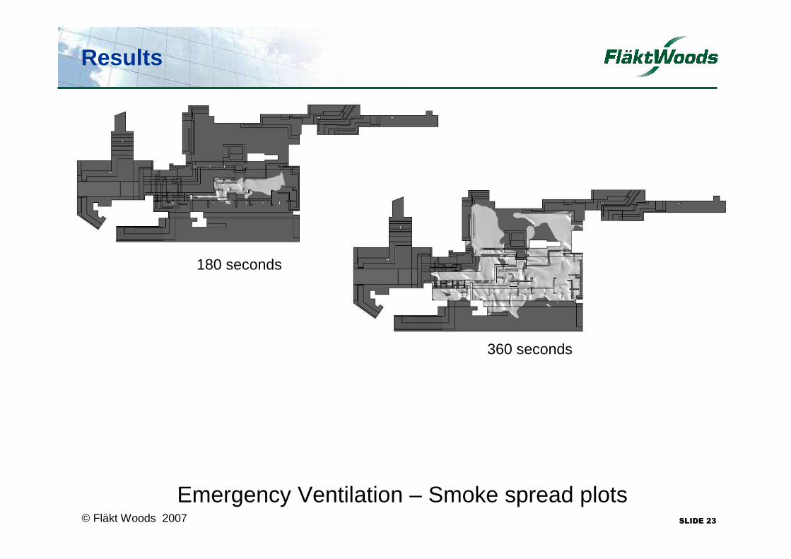
Emergency Ventilation – Smoke spread plotsSLIDE 23
180 seconds
360 seconds

© Fläkt Woods 2007
Results
Emergency Ventilation – Smoke spread plotsSLIDE 24
360 seconds

© Fläkt Woods 2007
Results
Emergency Ventilation – Smoke TestSLIDE 25
© Fläkt Woods 2007
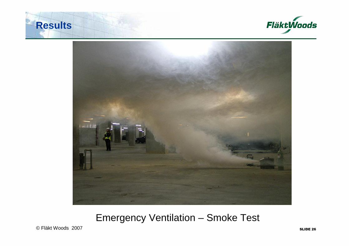
Results
Emergency Ventilation – Smoke TestSLIDE 26

© Fläkt Woods 2007
Summary & Conclusions
SLIDE 27

© Fläkt Woods 2007
Summary & Conclusions
• The results of the CFD analysis demonstrate that the scheme provides a good distribution of air throughout the car park prior to extraction, for both general and emergency ventilation scenarios.
• The ventilation system provides good smoke control in the case of a fire taking place Basement Level 1.
SLIDE 28

© Fläkt Woods 2007
Any Questions???
Conclusion
This presentation and any accompanying notes are copyright of Fläkt Woods Limited and should not be copied or reproduced without written permission. Please note that figures in this presentation should NOT be applied to any project designs without the express
written permission of Fläkt Woods Limited
SLIDE 29