car collision warning system based on rtk gps · ts 1c - development in gnss measurement...
TRANSCRIPT

TS 1C - Development in GNSS Measurement Technologies and Techniques
Milan Horemuž
Car Collision Warning System Based on RTK GPS
Integrating Generations
FIG Working Week 2008
Stockholm, Sweden 14-19 June 2008
1/13
Car Collision Warning System Based on RTK GPS
Milan HOREMUZ, Sweden
Key words: RTK, GPS, road safety, Kalman filter
SUMMARY
Many serious traffic accidents happen when a car drives over to the opposite lane. An
effective way to prevent such accidents is to mount a barrier between opposite driving
directions in form of cable fence. This is a quite expensive solution, which is not applicable
on all roads. Therefore it is desirable to find alternative methods.
One possible alternative is to use GPS, namely a RTK method (Real Time Kinematics), which
is capable to deliver sufficiently accurate position to compute if the car drives in correct lane
and if the distance to the road edge is safe. The basic concept of the warning system is to
place the actual position of the car into a precise road model and to compute if the car is
outside or on its way out of the correct lane. If so, the system will warn the driver.
This paper describes a prototype of such a warning system. The system was tested on 10 km
long road section. The car performed 38 intentional manoeuvres that should trigger alarm.
The evaluation of the tests was done visually, using video sequence synchronised with the
graphical output from the warning system. 32 manoeuvres were correctly alarmed by the
system. The system issued 32 false alarms during 40 minutes driving. However, most of them
had only short duration, less than 0.2 s.

TS 1C - Development in GNSS Measurement Technologies and Techniques
Milan Horemuž
Car Collision Warning System Based on RTK GPS
Integrating Generations
FIG Working Week 2008
Stockholm, Sweden 14-19 June 2008
2/13
Car Collision Warning System Based on RTK GPS
Milan HOREMUZ, Sweden
1. INTRODUCTION
Many serious traffic accidents occur when a car drives over to the opposite lane. An effective
way to prevent such accidents is to mount a barrier between lanes in form of cable fence. This
is quite expensive solution, which is not applicable on all roads. Therefore it is desirable to
find alternative methods.
One possibility is to use a collision avoidance system based on camera and radar sensors,
which are available on the market, for example Barber and Clarke (1998), Jansson e. al
(2002). Such systems use radar sensor to determine the range and relative velocity between
the car and other objects. The camera with image analysis software can determine the position
of the car relative to the lane painting. The collision avoidance systems are performing very
well in avoiding collisions between cars travelling in the same lane and in the same direction.
It is more difficult to handle the scenarios where the car is meeting another car travelling in
opposite direction. In this case, the meeting car can be falsely identified as a collision object,
especially in curves. The weakness of the camera sensor is weather and visibility dependency.
For example the road edges cannot be reliably recognised from the images if there is snow
coverage on the road.
In this paper we study the possibility use GPS, namely RTK method (Real Time Kinematics),
which is today routinely used for machine guidance, for example Baertlein at. al. (2000). This
method is capable to deliver sufficiently accurate position to compute if the car drives in
correct lane and if the distance to the road edge is safe. The basic concept of the warning
system is to place the actual position of the car into a precise road model and to compute if the
car is outside or on its way outside the correct lane. If so, the system will warn the driver.
The warning system consists of two components: a GPS receiver with RTK function and a
computer with software that evaluates the position of the car relative to the road model and
issues warning if the car is outside or is heading outside the correct lane. We named this
system VSKTH (Varningssystem KTH). The prototype was tested with GPS receiver Trimble
R7, which updates the position 20 times per second.
2. ANALYSIS AND SYSTEM SPECIFICATION
2.1 Positioning sensor
The warning system is built solely on GPS sensor with real time kinematics (RTK)
functionality. It means that the receiver must be able to receive RTK corrections either via
radio modem or via GSM modem. The corrections are generated by one or more reference
receivers. The precision in horizontal position is according to the manufacturer’s specification
10 mm + 1ppm, where ppm (parts per million) is distance dependent part of the error. It

TS 1C - Development in GNSS Measurement Technologies and Techniques
Milan Horemuž
Car Collision Warning System Based on RTK GPS
Integrating Generations
FIG Working Week 2008
Stockholm, Sweden 14-19 June 2008
3/13
expresses the growth of the positional error in millimetres per kilometre distance from
reference station. This precision is valid for synchronized RTK mode. In this mode the GPS
receiver waits for the corrections, which are generated with 1 Hz frequency. It means that the
position is available only once per second with certain delay, which depends on the
communication link between reference and roving receiver. The delay is in range of 1 – 2 s. In
this application a higher update frequency and shorter delay is required. Therefore it is more
suitable to use so called low-latency mode, in which the roving receiver uses ”older”
corrections to compute current position. In this way it is possible to compute position
immediately after the roving receiver performs observations towards satellites. Today, there
are receivers on the market with up to 20 Hz position update frequency. The drawback of this
mode is lower precision: 20 mm + 1 ppm. The position is delivered with delay 20 ms
(Trimble 2003), which is caused by receiver’s hardware and software; in the following text
we will denote it as hardware delay HD.
How the delay and the update frequency affect the performance of the warning system?
Generally we can state that the warning system can detect the change in the driving direction
faster, if the sensor has higher update frequency and shorter delay. The system issues a
warning based on the computed lateral distance dL, dR between the car and the edge of the
road – see Figure 1.
Dangerous
zone
Driving
direction
dL dR
dmin
Road edge
Figure 1. Dangerous zone, lateral distance d and error in course .
If the distance is less than a critical value dmin, then the car is in dangerous zone. The
performance of the warning system depends on the ability to compute actual lateral distance d
and it depends on update frequency f and hardware delay HD. If we consider that we need at
least one position update to compute the driving direction, then the total delay TD, i.e.
difference between time of last known position and the time when the warning system
computes and displays new position is given by:

TS 1C - Development in GNSS Measurement Technologies and Techniques
Milan Horemuž
Car Collision Warning System Based on RTK GPS
Integrating Generations
FIG Working Week 2008
Stockholm, Sweden 14-19 June 2008
4/13
1
TD HDf
(1)
We can say that during time TD the motion of the car is not sensed and the lateral distance is
changed by d. d depends on the velocity of the car, error in course , update frequency f
and hardware delay HD. Table 1 lists numerical values of d computed for car velocity 90
km/h. These values can be used for choosing a suitable value for safety marginal dmin.
Table 1. Values of d computed for velocity 90 km/h
Update frequency
f
[Hz]
d ( = 1)
[m]
d ( = 2)
[m]
d ( = 5)
[m]
1 0.45 0.91 2.27
5 0.10 0.21 0.52
10 0.06 0.12 0.31
20 0.04 0.08 0.20
2.2 Precision of GPS position
Depending on availability of RTK corrections and the quality of GPS signals, there are four
types of solution that a RTK GPS receiver can produce:
1. RTK fixed solution, expected precision is on cm-level. This solution is available only
when uninterrupted GPS phase observations and RTK corrections are available.
2. RTK float solution, expected precision is on dm-level. This solution is typically
available shortly after the start of the receiver or after the re-acquiring of GPS signal or RTK
corrections.
3. DGPS solution, expected precision is 1 - 3 m. In this case the RTK corrections are
available, but GPS signal is too weak to perform phase observations. This is usually the case
when many of available satellites are behind the trees.
4. Autonomous solution, precision 10 - 20 m. This solution is generated, if the RTK
corrections are not available.
2.3 Road model
A precise road model is a prerequisite for correct functionality of the warning system. By road
model we understand a database of coordinates of points that describe the geometry of road.
Such database can be created by surveying discrete points along the road’s edges or along the
middle line. The method of surveying should guarantee sufficient accuracy; preferably below
0.15 m. Usually the existing databases are not accurate enough for this purpose. In the
following text a section of the road between two surveyed points will be referred as segment.
TS 1C - Development in GNSS Measurement Technologies and Techniques
Milan Horemuž
Car Collision Warning System Based on RTK GPS
Integrating Generations
FIG Working Week 2008
Stockholm, Sweden 14-19 June 2008
5/13
3. KINEMATIC MODEL FOR POSITIONING
Kalman filter seems to be the most appropriate tool for the computation of position, velocity
and acceleration of the car in real time. We use PVA (position velocity acceleration) model to
describe the motion of the car (Schwarz et. al. 1989). We have chosen this model, because we
assume that the car undergoes just smooth motions, without any abrupt changes of
acceleration and the driving direction. In this model, the kinematic state of the car is described
by six parameters:
T
x y x yx y v v a a x (2)
where
x, y are horizontal coordinates expressed in Swedish national reference system RT90
vx, vy are x and y components of velocity
ax, ay are x and y components of acceleration
A kinematic model can be generally written in linear form as:
x Fx Gu (3)
where F is dynamic matrix, which in case of PVA model takes following form:
0 0 1 0 0 0
0 0 0 1 0 0
0 0 0 0 1 0
0 0 0 0 0 1
0 0 0 0 0 0
0 0 0 0 0 0
F (4)
ax
ax
0 0
0 0
0 0,
0 0
1 0
0 1
G u (5)
G is a shaping matrix and u is a vector of random acceleration with covariance matrix
axT
ay
q 0E s t
0 q
Q u u . (6)

TS 1C - Development in GNSS Measurement Technologies and Techniques
Milan Horemuž
Car Collision Warning System Based on RTK GPS
Integrating Generations
FIG Working Week 2008
Stockholm, Sweden 14-19 June 2008
6/13
The choice of the numerical values of q in matrix Q determines the weight of the predicted
parameters x. In other words, matrix Q expresses the degree of correctness of the PVA model.
Value q = 0 means that we assume perfect conformance of the model with reality. If we set
too low values of q, then there is a risk that the system will detect the change of the driving
direction with larger time delay. For this reason we used relatively high, empirically
determined value q = 0.1 2 3 1/2m s Hz . By doing so, the filter relays more on the current
observation and the computed trajectory of the car will not be as smooth as it would be using
smaller values of q.
We used standard Kalman filter formulation described in Brown (1992) with the following
steps:
1. Initialisation: estimation of starting values for position, velocity, acceleration and their
covariance matrix. We use three consequent measured positions (x1, y1, … x3, y3) for the
computation of these values:
T
3 2 3 2 3 2 1 3 2 10 3 3 2 2
x x y y x 2x x y 2y yx y
t t t t
x (7)
2 2 22y y y2 2 x
x,0 x y 2 2 4 4
2 2 44diag
t t t t
Q (8)
2. Prediction:
T
k k 1 x,k x,k 1 k, x T x Q T Q T Q (9)
3. Computation of gain matrix:
1
T T
k x,k k k k x,k k
K Q H R H Q H (10)
4. Update state vector using measurements from current epoch:
k k k k k kˆ x x K L H x (11)
Store state variables for the next epoch:
k kˆx x (12)
5. Update covariance matrix:
x,k k k x,kˆ Q I K H Q (13)

TS 1C - Development in GNSS Measurement Technologies and Techniques
Milan Horemuž
Car Collision Warning System Based on RTK GPS
Integrating Generations
FIG Working Week 2008
Stockholm, Sweden 14-19 June 2008
7/13
Store covariance matrix for next epoch:
x,k x,kˆQ Q (14)
Steps 2 to 5 are repeated for everey new GPS observation. Symbol (^) denotes the optimum
estimate and subscript k denotes epoch number. T is transition matrix that can be obtained by
solving the differential equation (3):
2
2
t
1 0 t 0 t / 2 0
0 1 0 t 0 t / 2
0 0 1 0 t 0e
0 0 0 1 0 t
0 0 0 0 1 0
0 0 0 0 0 1
FT (15)
t is time interval between GPS observations. L denotes vector of observations, i.e. horizontal
coordinates expressed in national reference system:
T
k x yL (16)
R is covariance matrix of observations:
2
x
2
y
0
0
R (17)
The elements of this matrix are available together with the coordinates from GPS receiver.
H is design matrix that relates state vector with observations:
1 0 0 0 0 0
0 1 0 0 0 0
H (18)
Qk is covariance matrix of wk given by:
k 1
k k 1,
k
d
w T G u (19)

TS 1C - Development in GNSS Measurement Technologies and Techniques
Milan Horemuž
Car Collision Warning System Based on RTK GPS
Integrating Generations
FIG Working Week 2008
Stockholm, Sweden 14-19 June 2008
8/13
5 4 3
ax ax ax
5 4 3
ay ay ay
4 3 2
ax ax axT
k k k 4 3 2
ay ay ay
3 2
ax ax ax
3 2
ay ay ay
t q / 20 0 t q /8 0 t q / 6 0
0 t q / 20 0 t q /8 0 t q / 6
t q /8 0 t q / 3 0 t q / 2 0E
0 t q /8 0 t q / 3 0 t q / 2
t q / 6 0 t q / 2 0 q t 0
0 t q / 6 0 t q / 2 0 q t
Q w w
(20)
4. DESCRIPTION OF ALGORITHM
The software reads in position from GPS receiver, finds the segment in the road model and
computes the distance to the road edges. If the distance is shorter than critical value dmin, then
the system triggers alarm “In dangerous zone”. The GPS position is then used to update state
vector using the above-described Kalman filter and predicted position (3 s ahead) is
computed. If this predicted position falls into the dangerous zone, the alarm “Heading into
dangerous zone” is triggered. In the next step, the software computes the difference between
the direction of the road and computed direction of velocity vector. If this difference is
statistically larger than zero, then alarm “Wrong course” is triggered.
5. TEST SETUP
We tested the warning system on road number 68, approximately 10 km stretch between cities
Horndal och Hästbo, located 150 km west from Stockholm. This part of the road was
surveyed by mobile mapping system Visimind, which is based on combination of GPS,
inertial navigation and digital camera sensors. The standard error of surveyed coordinates is
15 cm. The result from this surveying was a list of coordinates of points on the middle line
and the width of the road. The distance between surveyed points was 10 m on straight sections
and 5 m in curves.
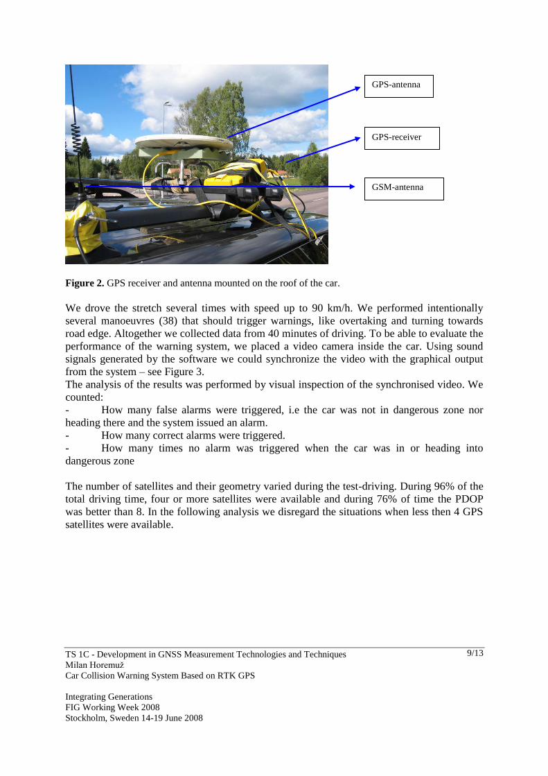
During this experiment we used GPS receiver Trimble R7 with antenna Zephyr placed on the
roof of the car – see Figure 2.
TS 1C - Development in GNSS Measurement Technologies and Techniques
Milan Horemuž
Car Collision Warning System Based on RTK GPS
Integrating Generations
FIG Working Week 2008
Stockholm, Sweden 14-19 June 2008
9/13
Figure 2. GPS receiver and antenna mounted on the roof of the car.
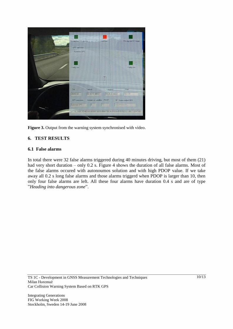
We drove the stretch several times with speed up to 90 km/h. We performed intentionally
several manoeuvres (38) that should trigger warnings, like overtaking and turning towards
road edge. Altogether we collected data from 40 minutes of driving. To be able to evaluate the
performance of the warning system, we placed a video camera inside the car. Using sound
signals generated by the software we could synchronize the video with the graphical output
from the system – see Figure 3.
The analysis of the results was performed by visual inspection of the synchronised video. We
counted:
- How many false alarms were triggered, i.e the car was not in dangerous zone nor
heading there and the system issued an alarm.
- How many correct alarms were triggered.
- How many times no alarm was triggered when the car was in or heading into
dangerous zone
The number of satellites and their geometry varied during the test-driving. During 96% of the
total driving time, four or more satellites were available and during 76% of time the PDOP
was better than 8. In the following analysis we disregard the situations when less then 4 GPS
satellites were available.
GPS-receiver
GPS-antenna
GSM-antenna
TS 1C - Development in GNSS Measurement Technologies and Techniques
Milan Horemuž
Car Collision Warning System Based on RTK GPS
Integrating Generations
FIG Working Week 2008
Stockholm, Sweden 14-19 June 2008
10/13
Figure 3. Output from the warning system synchronised with video.
6. TEST RESULTS
6.1 False alarms
In total there were 32 false alarms triggered during 40 minutes driving, but most of them (21)
had very short duration – only 0.2 s. Figure 4 shows the duration of all false alarms. Most of
the false alarms occured with autonoumos solution and with high PDOP value. If we take
away all 0.2 s long false alarms and those alarms triggerd when PDOP is larger than 10, then
only four false alarms are left. All these four alarms have duration 0.4 s and are of type
”Heading into dangerous zone”.

TS 1C - Development in GNSS Measurement Technologies and Techniques
Milan Horemuž
Car Collision Warning System Based on RTK GPS
Integrating Generations
FIG Working Week 2008
Stockholm, Sweden 14-19 June 2008
11/13
Duration of false alarms [s]
0.2
66%
0.4
13%
0.6
3%
3
6%
4
3%
2
6%
0.8
3%
Figure 4. Duration of false alarms .
6.2 Correct alarms
During test-driving we did 38 different manoeuvres that should trigger an alarm. In 32 cases
the alarm was issued correctly and in 6 manoeuvres no alarm was triggered. This happened
with autonomous (4x) and DGPS (2x) solution. In all these 6 manoeuvres the system showed
the position of the car correctly, i.e. in dangerous zone, but the alarm was not triggered
because of low precision of the GPS solutions. System issues an alarm only if the car is in
dangerous zone with 99% probability. Figure 5 shows the type of GPS solution when the
correct alarms were triggered.
Autonom
6% DGPS
13%
RTK float
16%RTK fixed
65%
Figure 5. Type of solution when correct alarms were triggered.

TS 1C - Development in GNSS Measurement Technologies and Techniques
Milan Horemuž
Car Collision Warning System Based on RTK GPS
Integrating Generations
FIG Working Week 2008
Stockholm, Sweden 14-19 June 2008
12/13
7. CONCLUSIONS
Based on the analysis of the test-driving, we can conclude that the system works satisfactory
if RTK float or RTK fixed solution is available. This is usually the case in open areas outside
the cities. When driving in urban areas, the signals from satellites are often interrupted or
blocked by obstacles.
During our test the system issued quite many false alarms, which can be disturbing for driver.
Most of these alarms were of type “Heading into dangerous zone” and “Wrong course”. We
have shown that the number of the false alarms can be decreased significantly, if the alarm is
issued only in the case when it is computed during time period longer than 0.2 s. Another
reason for false alarms was bad satellite geometry, i.e. large PDOP, so it is necessary to
weight down the observations with large PDOP.
Our test showed that the autonomous solution has better precision than expected. If PDOP
value was less than 8, the system showed correct position of the car relative to the road edges.
Even during manoeuvres the computed position was in very good agreement with real
position of the car.
Despite of very promising results shown by our test, currently there are limitations that
prevent broader use of such system. First of all, in many countries, including Sweden, the
precision of existing road models is not sufficient for this purpose. Secondly, the price of
RTK GPS receivers is high. This is because of relatively small user group of such receivers.
But it can be assumed that the price will decrease with increasing number of users. Another
issue is availability of RTK corrections. Currently there are just limited areas covered by such
corrections but it can be assumed that the coverage will grow as the demand for this service is
also growing.
Since the purpose of this project was to study feasibility of using GPS as a sensor in the
warning system, we did not address all issues connected to practical implementation of the
system, like integrity and reliability of GPS, detection of sensor failures, the form of alarm
suitable for driver, etc. It should be also pointed out that GPS has its advantages and
limitations. This is statement is true for other navigation sensors as well. Therefore it would
be beneficial to add other complementing sensors that can provide positional information
when the GPS solution ids not available.
8. LIST OF ABBREVIATIONS
GSM Global System for Mobile communications
f position update frequency
HD hardware delay
TD total delay
PDOP Positional Dilution of Precision, a number that describes the effect of satellites
geometry on the positioning precision. The lower PDOP is the better precision is expected.
Usually a value below 8 is acceptable.
TS 1C - Development in GNSS Measurement Technologies and Techniques
Milan Horemuž
Car Collision Warning System Based on RTK GPS
Integrating Generations
FIG Working Week 2008
Stockholm, Sweden 14-19 June 2008
13/13
RTK Real Time Kinematic
GPS Global Positioning System
REFERENCES
Barber P., Clarke N. (1998) Advanced Collision Warning Systems. Industrial Automation and
Control: Applications in the Automotive Industry (Digest No.1998/234).
Brown R., G., Whang, P., Y., C. (1992). Introduction to random signals and applied Kalman
filtering. Wiley & Sons, New York, Chichester, Toronto, Brisbane, Singapore.
Jansson J., Ekmark J., Gustafsson F. (2002). Decision Making for Collision Avoidance
Systems. Society of Automotive Engineers, 2002-01-0403.
Trimble (2003). MS series Operation Manual. Version 1.5. Part Number 40868-03-ENG.
Revision A, TRIMBLE.
Baertlein H., Carlson B, Eckels R., Lyle S and Wilson S. (2000). A High-Performance, High-
Accuracy RTK GPS Machine Guidance System. GPS Solutions. Volume 3, Number 3, pp 4 –
11. Springer Berlin, Heidelberg
Schwarz K. P., Cannon M. E. and Wong R. V. C. (1989). A comparison of GPS kinematic
models for determination of position and velocity along a trajectory. Manuscripta geodaetica
14: 345 – 353. Springer-Verlag.
BIOGRAPHICAL NOTES
Milan Horemuž, PhD. is employed as researcher in the Royal Institute of Technology in
Stockholm since 1996. Previously he worked in Slovak Technical University in Bratislava
where he received his PhD degree in geodesy. His current research interest is precise GPS
positioning for deformation measurements and application in traffic research.
CONTACTS
Horemuz Milan, PhD
Royal Institute of Technology
Department of Transport and Economics
Division of Geodesy
Teknikringen 72
100 44 Stockholm
SWEDEN
Tel. + 46 8 790 73 35
Fax + 46 8 790 73 43
Email: [email protected]
Web site: http://www.infra.kth.se/geo/