capacitors for ac and dc general purpose … and dc general purpose applications capacitor...
TRANSCRIPT

www.regalbeloitcapacitors.com
CPD 512
03 / 07
Capacitors for AC and DC General Purpose Applications
Capacitor Application Data Sheet
PRIMARY INFORMATION ( Essential )
1. Application: ________________________________________________________________________________ 2. Capacitance:_______________________Tolerance:_______________________________________________
3. Peak Voltage:_____________________RMS Voltage: ____________________________________________
4. Peak Current:____________________ RMS Current: ____________________________________________
5. Transient Voltage:_______________Duration:_____________Freq. of Occurrence:__________________
6. Frequency or Repetition Rate (Hz):________________Duty Cycle:________________________________
7. Ambient Temperature: _______________Max.:_______________Min.:_____________________________
8. Capacitor Charge Time: ______________Discharge Time:_______________________________________
9. Required Operating Life (Hours): ____________________________________________________________
10. Waveforms:
SECONDARY INFORMATION (Provide as Appropriate)
11. Physical Size Limitations: _________________________________________________________________ 12. Mounting Requirements: _________________________________________________________________ 13. Applicable Specifications: ________________________________________________________________ 14. Type of Cooling Available: ________________________________________________________________ 15. Unusual Atmospheric Conditions: ________________________________________________________ 16. Other Special Requirements: _____________________________________________________________
17. Number of Samples Required: _______________18. Potential Usage: __________________________
CPD 512 – 03/ 07 www.regalbeloitcapacitors.com
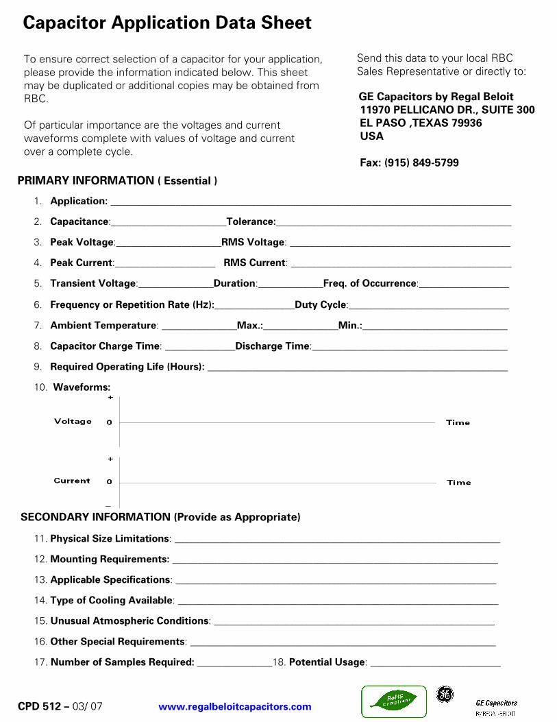
To ensure correct selection of a capacitor for your application, please provide the information indicated below. This sheet may be duplicated or additional copies may be obtained from RBC. Of particular importance are the voltages and current waveforms complete with values of voltage and current over a complete cycle.
Send this data to your local RBC Sales Representative or directly to:
GE Capacitors by Regal Beloit 11970 PELLICANO DR., SUITE 300 EL PASO ,TEXAS 79936 USA Fax: (915) 849-5799

CPD 512– 03 / 07 www.regalbeloitcapacitors.com
1
Table of Contents
Descriptive Information 1 Product Safety 3 General Purpose AC Capacitors-Gem III (240-370VAC) 4 Application Notes/ Technical Data 6 General Purpose AC Capacitors-Gem III (600 VAC) 10 Application Notes/ Technical Data 12 General Purpose AC Capacitors-Gem III (660 VAC) (Series Section) 16 Application Notes/ Technical Data 18 Cross Reference 660 Volt AC 22 Dual Rated Capacitors 23 Mounting Hardware for Gem III Capacitors 25
Descriptive Information
RBC Capacitors for General Purpose Applications Metallized film capacitors are unsurpassed in terms of size, weight, performance, and reliability for ac applications. RBC - Capcom brings over 60 years of capacitor manufacturing experience to the product lines described in this publication. These capacitors represent the best in product design for long-term reliability and safe operation. RBC’s materials, product, and process development work continue to provide capacitor users with outstanding total value. The specific products in this bulletin are aimed at market/application segments for General Purpose, Power Supply and Electronic Power Conversion. The Gem III General Purpose Capacitors are used for filtering on a wide variety of light industrial equipment. The conversion of electrical power in uninterruptible power supplies and drive control systems requires filter capacitors. An application note is included to help customers in the correct choice and use of these capacitors.
CPD 512 – 03 / 07 www.regalbeloitcapacitors.com
2
Descriptive Information
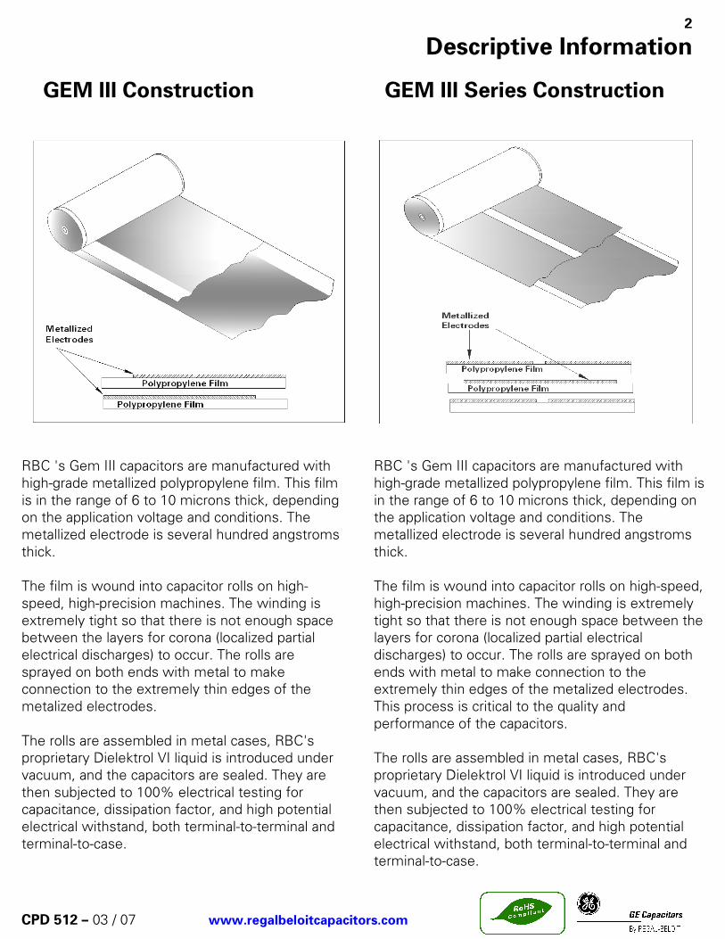
GEM III Construction GEM III Series Construction
RBC 's Gem III capacitors are manufactured with high-grade metallized polypropylene film. This film is in the range of 6 to 10 microns thick, depending on the application voltage and conditions. The metallized electrode is several hundred angstroms thick. The film is wound into capacitor rolls on high-speed, high-precision machines. The winding is extremely tight so that there is not enough space between the layers for corona (localized partial electrical discharges) to occur. The rolls are sprayed on both ends with metal to make connection to the extremely thin edges of the metalized electrodes. The rolls are assembled in metal cases, RBC's proprietary Dielektrol VI liquid is introduced under vacuum, and the capacitors are sealed. They are then subjected to 100% electrical testing for capacitance, dissipation factor, and high potential electrical withstand, both terminal-to-terminal and terminal-to-case.
RBC 's Gem III capacitors are manufactured with high-grade metallized polypropylene film. This film is in the range of 6 to 10 microns thick, depending on the application voltage and conditions. The metallized electrode is several hundred angstroms thick.
The film is wound into capacitor rolls on high-speed, high-precision machines. The winding is extremely tight so that there is not enough space between the layers for corona (localized partial electrical discharges) to occur. The rolls are sprayed on both ends with metal to make connection to the extremely thin edges of the metalized electrodes. This process is critical to the quality and performance of the capacitors.
The rolls are assembled in metal cases, RBC's proprietary Dielektrol VI liquid is introduced under vacuum, and the capacitors are sealed. They are then subjected to 100% electrical testing for capacitance, dissipation factor, and high potential electrical withstand, both terminal-to-terminal and terminal-to-case.
Product Safety 3
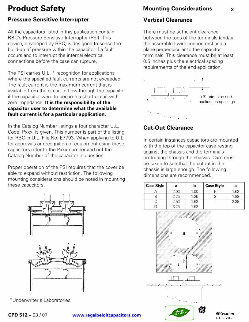
Case Style a b Case Style a
A 2.00 1.00 P 1.62B 2.25 1.25 S 1.88C 2.50 1.62 T 2.38D 3.25 1.62
*Underwriter's Laboratories
CPD 512 – 03 / 07 www.regalbeloitcapacitors.com
Pressure Sensitive Interrupter All the capacitors listed in this publication contain RBC's Pressure Sensitive Interrupter (PSI). This device, developed by RBC, is designed to sense the build-up of pressure within the capacitor if a fault occurs and to interrupt the internal electrical connections before the case can rupture. The PSI carries U.L. * recognition for applications where the specified fault currents are not exceeded. The fault current is the maximum current that is available from the circuit to flow through the capacitor if the capacitor were to become a short circuit with zero impedance. It is the responsibility of the capacitor user to determine what the available fault current is for a particular application. In the Catalog Number listings a four character U.L. Code, Pxxx, is given. This number is part of the listing for RBC in U.L. File No. E7793. When applying to U.L. for approvals or recognition of equipment using these capacitors refer to the Pxxx number and not the Catalog Number of the capacitor in question. Proper operation of the PSI requires that the cover be able to expand without restriction. The following mounting considerations should be noted in mounting these capacitors.
Mounting Considerations Vertical Clearance There must be sufficient clearance between the tops of the terminals (and/or the assembled wire connectors) and a plane perpendicular to the capacitor terminals. This clearance must be at least 0.5 inches plus the electrical spacing requirements of the end application.
Cut-Out Clearance In certain instances capacitors are mounted with the top of the capacitor case resting against the chassis and the terminals protruding through the chassis. Care must be taken to see that the cutout in the chassis is large enough. The following dimensions are recommended.

General Purpose AC Capacitors – Gem III 4
SPECIFICATIONS: Available Capacitance Range: 2 to 120 µF Capacitance Tolerance: ± 6% Capacitance Variation with Temperature: See chart E-3 on page 9. Rated Voltage: See Rating Tables. Rating is the 60Hz RMS voltage for a
sinusoidal waveform. For other waveforms refer to the Application Note on page 6.
Leakage Current: 30 µA maximum Frequency: 50/60 Hz. For higher frequencies refer to the Application.
Note on page 7. Operating Temperature: -40 ˚C to +70 ˚C Storage Temperature: -40 ˚C to +90 ˚C Operating Life: 60,000 hours with 94% survival Dissipation Factor: 0.1% maximum Case Material/Finish: Unpainted Aluminum case, Ternplate steel cover. Terminations: 0.250” x 0.031” quick connect blades. Dielectric Fluid: Dielektrol VI Internal Protection: UL recognized Pressure Sensitive Interrupter. See Ratings
Table for RBC’s Code Number listed under RBC’s UL. File E7793 (N). For UL submittals with these capacitors use the RBC ’Pxxx’ number not the Catalog Number. The corresponding generic UL designation that includes the Available Fault Current (AFC) rating is given below. All these capacitors are capable of interrupting available fault currents of up to 10,000 amperes.
Case Style RBC Code Generic UL Code
A P921 A10000AFCP P965 P10000AFCS P968 S10000AFCT P969 T10000AFC
CPD 512 – 03 / 07 www.regalbeloitcapacitors.com
240 and 370 Volts AC This series of Gem III is specifically designed for applications such as AC filters where harmonic frequencies greater than 60Hz are common. Application Data is provided starting on page 5 that gives the Equivalent Series Resistance (ESR) for these units. This allows the user to calculate the losses for each design/application and to ensure that they are kept within the permissible limits. Any questions regarding the suitability of a capacitor for a particular application may be referred to RBC Engineers through your RBC sales representative.

* It is RBC’s goal to serve you with the most cost effective and the highest quality capacitor designs. Standardization to the catalog type shown is a major program at RBC. However, RBC remains sensitive to your needs and requirements, and will continue to offer the above ratings (and more) in case configurations to meet your application (s).
General Purpose AC Capacitors – Gem III 5
CPD 512 – 03 / 07 www.regalbeloitcapacitors.com
Case Style A
240 and 370 Volts AC *STANDARD RATINGS Case Style P, S, and T
Capacitance (µµµµF)
CatalogNumber
CaseStyle
HeightC (ins)
ULCode
15 97F8036 P 2.88 P96525 97F8037 P 2.88 P96530 97F8038 P 3.88 P96535 97F8039 P 3.88 P96540 97F8040 P 3.88 P96545 97F8041 P 4.75 P96550 97F8042 P 4.75 P96555 97F8043 P 4.75 P965
60 97F8044 S 4.75 P96865 97F8045 S 4.75 P96870 97F8046 S 4.75 P96875 97F8047 S 4.75 P968
80 97F8048 T 3.88 P96985 97F8049 T 3.88 P96990 97F8050 T 3.88 P96995 97F8051 T 4.75 P969100 97F8052 T 4.75 P969120 97F8053 T 4.75 P969
3 97F8054 A 2.12 P9214 97F8055 A 2.12 P9215 97F8056 A 2.88 P9216 97F8057 A 2.88 P9217.5 97F8058 A 2.88 P92110 97F8059 A 3.88 P92112.5 97F8060 A 3.88 P921
15 97F8061 P 2.88 P96517.5 97F8062 P 2.88 P96520 97F8063 P 3.88 P96525 97F8064 P 3.88 P96530 97F8065 P 3.88 P96535 97F8066 P 4.75 P96540 97F8067 P 4.75 P965
45 97F8068 S 4.75 P96850 97F8069 S 4.75 P96855 97F8070 S 4.75 P968
60 97F8071 T 3.88 P96965 97F8072 T 3.88 P96970 97F8073 T 4.75 P969
240 Volts A-C Nominal
370 Volts A-C Nominal

Application Note 6
CatalogNumber
µµµµFESRohms
CurveNumber
97F8036 15 0.0257 2
97F8037 25 0.0180 2
97F8038 30 0.0228 3
97F8039 35 0.0206 3
97F8040 40 0.0190 3
97F8041 45 0.0241 4
97F8042 50 0.0226 4
97F8043 55 0.0213 4
97F8044 60 0.0215 5
97F8045 65 0.0206 5
97F8046 70 0.0198 5
97F8047 75 0.0191 5
97F8048 80 0.0164 5
97F8049 85 0.0160 5
97F8050 90 0.0156 5
97F8051 95 0.0193 6
97F8052 100 0.0189 6
97F8053 120 0.0176 6
97F8054 3 0.0700 1
97F8055 4 0.0539 1
97F8056 5 0.0586 2
97F8057 6 0.0499 2
97F8058 7.5 0.0411 2
97F8059 10 0.0471 3
97F8060 12.5 0.0392 3
97F8061 15 0.0244 2
97F8062 17.5 0.0218 2
97F8063 20 0.0281 3
97F8064 25 0.0240 3
97F8065 30 0.0213 3
97F8066 35 0.0262 4
97F8067 40 0.0240 4
97F8068 45 0.0235 5
97F8069 50 0.0222 5
97F8070 55 0.0210 5
97F8071 60 0.0175 5
97F8072 65 0.0169 5
97F8073 70 0.0207 6
240 Volts AC Nominal
370 Volts AC Nominal
CPD 512 – 03 / 07 www.regalbeloitcapacitors.com
97F8000 Series 240 and 370 Volts AC The 97F8000 series of capacitors may be used in AC applications where the voltage waveform is non-sinusoidal. This Application Note is provided to assist in the correct use of the capacitors where higher frequency harmonic currents are present. If you need further assistance please contact RBC’s Capacitors Operation through your normal sales channel. Higher frequency currents are commonly encountered in the filter circuits of Static Power Converters. These frequencies range from 180 to 1500 Hz for a 60 Hz system in various combinations of the odd harmonics depending on the type of converter. Generally, there are not significant harmonic currents above the 25th harmonic. These capacitors can carry a total current of up to 15 amperes RMS (fundamental plus harmonics). The Equivalent Series Resistance (ERS) for each Catalog Number is shown in the ESR tables on this page. This value may be used to calculate the expected watts loss for a particular application. The user must determine the total RMS current (fundamental plus harmonics) for the application. The watts loss is then calculated using the equation:
W = I 2 x ESR
Where I = Total RMS current And ESR= Value from ESR tables. The calculated watts from this equation must not exceed the allowable watts loss shown on the curve corresponding to the particular capacitor. Two sets of curves are shown, one for natural circulation and one for forced air circulation.
NOTES (1) In no case should the total RMS current of 15 amperes be exceeded for any of these capacitors. (2) Running the capacitors at case temperatures above 70 ºC will have a significant effect on expected life. (See chart G-1 on page 8 ) (3) Running the capacitors at voltages above the nominal rated voltage will also result in significantly reduced life. (See chart G-2 on page 8 )

Allowable Watts Loss - 97F8000 ( 240 and 370 Volt ) Series 7
CPD 512 – 03 / 07 www.regalbeloitcapacitors.com
Natural Circulation Maximum Allowable Watts Loss
Ambient Temperature (ºC) – Natural Circulation
Allowable Watts Loss - 97F8000 ( 240 and 370 Volt ) Series
Forced Circulation Maximum Allowable Watts Loss Ambient Temperature (ºC) – Forced Circulation

General Purpose AC Capacitors – Gem III Application Data 8
CPD 512 – 03 / 07 www.regalbeloitcapacitors.com
Life Vs
Temperature
% of Chart G-1 Life
Degrees ˚C
Life Vs
Voltage
% of Rated Chart G-2 Life
% of Rated Voltage

General Purpose AC Capacitors – Gem III Application Data 9
CPD 512 – 03 / 07 www.regalbeloitcapacitors.com
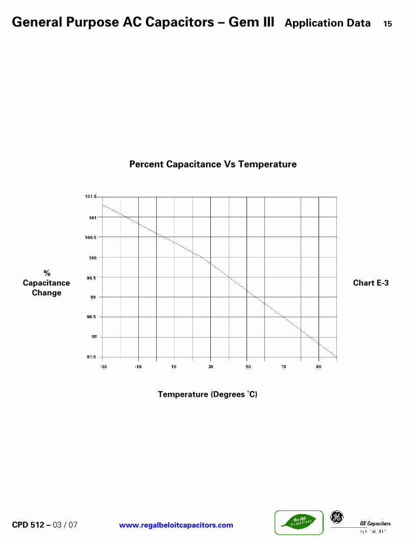
Percent Capacitance Vs Temperature
% Capacitance Chart E-3 Change
Temperature ( Degrees ˚C)

General Purpose AC Capacitors – Gem III 10
SPECIFICATIONS: Available Capacitance Range: 1.5 to 45 µF Capacitance Tolerance: ± 6% Capacitance Variation with Temperature: See chart E-3 on page 15. Rated Voltage: See Rating Tables. Rating is the 60Hz RMS voltage for a
sinusoidal waveform. For other waveforms refer to the Application Note on page 15.
Leakage Current: 30 µA maximum Frequency: 50/60 Hz. For higher frequencies refer to the
Application. Operating Temperature: -40 ˚C to +70 ˚C Storage Temperature: -40 ˚C to +90 ˚C Operating Life: 60,000 hours with 94% survival Dissipation Factor: 0.1% maximum Case Material/Finish: Unpainted Aluminum Contact factory for material /
finish to meet UL outdoor standards if required. Terminations: 0.250” x 0.031” quick connect blades. Dielectric Fluid: Dielektrol VI Internal Protection: UL recognized Pressure Sensitive Interrupter. See
Ratings Table for RBC’s Code Number listed under RBC’s UL. File E7793 (N). For UL submittals with these capacitors use the RBC ’Pxxx’ number not the Catalog Number. The corresponding generic UL designation that includes the Available Fault Current (AFC) rating is given below. All these capacitors are capable of interrupting available fault currents of up to 10,000 amperes.
CPD 512 – 03 / 07 www.regalbeloitcapacitors.com
Case Style RBC Code Generic UL Code
A P961 A10000AFC
B P962 B10000AFC
C P963 C10000AFC
D P964 D10000AFC
600 Volts AC This series of Gem III is specifically designed for general purpose AC applications in power supplies, UPS and power conversion equipment. Application Data is provided starting on page 12 that gives the Equivalent Series Resistance (ESR) for each unit. This allows the user to calculate the losses for each design/application and to ensure that they are kept within the permissible limits. Any questions regarding the suitability of a capacitor for a particular application may be referred to RBC Engineers through your RBC sales representative.

General Purpose AC Capacitors – Gem III 11
600 Volts AC
Case Style a bA 2.16 1.31B 2.69 1.56C 2.91 1.91D 3.66 1.97
Capacitance (µµµµF)
CatalogNumber
CaseStyle
HeightC(in.)
ULCode
1.5 97F8240 A 2.12 P961
2.0 97F8241 A 2.12 P961
2.5 97F8242 A 2.88 P961
3.0 97F8243 A 2.88 P961
4.0 97F8244 A 2.88 P961
5.0 97F8245 A 3.88 P961
6.0 97F8246 A 3.88 P961
7.0 97F8247 A 4.75 P961
8.0 97F8248 A 4.75 P961
10 97F8249 B 3.88 P962
12 97F8250 B 3.88 P962
15 97F8251 B 3.88 P962
18 97F8252 B 4.75 P962
20 97F8253 B 4.75 P962
25 97F8254 C 4.75 P963
30 97F8255 D 3.88 P964
35 97F8256 D 4.75 P964
40 97F8257 D 4.75 P964
45 97F8258 D 4.75 P964
600 Volts AC Nominal
CPD 512 – 03 / 07 www.regalbeloitcapacitors.com
*STANDARD RATINGS Case Style A, B, C and D
* It is RBC’s goal to serve you with the most cost effective and the highest quality capacitor designs. Standardization to the catalog type shown is a major program at RBC. However, RBC remains sensitive to your needs and requirements, and will continue to offer the above ratings (and more) in case configurations to meet your application (s).

Application Note 12
ERS Values for 97F8200 (600 Volt) Series.Curves Numbers refer to Graphs on next Page.
CatalogNumber
µµµµFESRohms
CurveNumber
97F8240 1.5 0.1277 1
97F8241 2.0 0.0971 1
97F8242 2.5 0.0984 2
97F8243 3.0 0.0831 2
97F8244 4.0 0.0639 2
97F8245 5.0 0.0723 3
97F8246 6.0 0.0615 3
97F8247 7.0 0.0739 4
97F8248 8.0 0.0657 4
97F8249 10.0 0.0404 4
97F8250 12.0 0.0366 4
97F8251 15.0 0.0309 4
97F8252 18.0 0.0361 5
97F8253 20.0 0.0334 5
97F8254 25.0 0.0294 5
97F8255 30.0 0.0220 5
97F8256 35.0 0.0258 6
97F8257 40.0 0.0240 6
97F8258 45.0 0.0225 6
600 Volts AC Nominal
CPD 512 – 03 / 07 www.regalbeloitcapacitors.com
97F8200 Series 600 Volts AC The 97F8000 series of capacitors on the attached product sheet may be used in AC applications where the voltage waveform is non-sinusoidal. This Application Note is provided to assist in the correct use of the capacitors where higher frequency harmonic currents are present. If you need further assistance please contact RBC’s Capacitors Operation through your normal sales channel. Higher frequency currents are commonly encountered in the filter circuits of Static Power Converters. These frequencies range from 180 to 1500 Hz for a 60 Hz system in various combinations of the odd harmonics depending on the type of converter. Generally, there are not significant harmonic currents above the 25th harmonic. These capacitors can carry a total current of up to 15 amperes RMS (fundamental plus harmonics). The Equivalent Series Resistance (ERS) for each Catalog Number is shown in the ESR tables on this page. This value may be used to calculate the expected watts loss for a particular application. The user must determine the total RMS current (fundamental plus harmonics) for the application. The watts loss is then calculated using the equation:
W = I 2 x ESR
Where I = Total RMS current And ESR= Value from ESR tables. The calculated watts from this equation must not exceed the allowable watts loss shown on the curve corresponding to the particular capacitor. Two sets of curves are shown, one for natural circulation and one for forced air circulation.
NOTES
(1) In no case should the total RMS current of 15 amperes be exceeded for any of these capacitors.
(2) Running the capacitors at case temperatures above 70 ºC will have a significant effect on expected life. (See chart G-1 on page 14 )
(3) Running the capacitors at voltages above the nominal rated voltage will also result in significantly reduced life. (See chart G-2 on page 14)
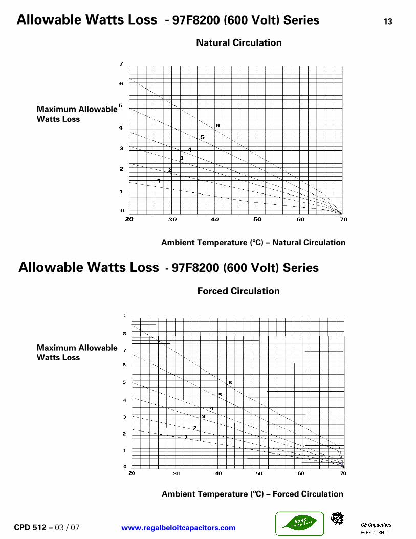
Allowable Watts Loss - 97F8200 (600 Volt) Series 13
CPD 512 – 03 / 07 www.regalbeloitcapacitors.com
Natural Circulation
Maximum Allowable Watts Loss
Ambient Temperature (ºC) – Natural Circulation
Allowable Watts Loss - 97F8200 (600 Volt) Series
Forced Circulation Maximum Allowable Watts Loss Ambient Temperature (ºC) – Forced Circulation

General Purpose AC Capacitors – Gem III Application Data 14
CPD 512 – 03 / 07 www.regalbeloitcapacitors.com
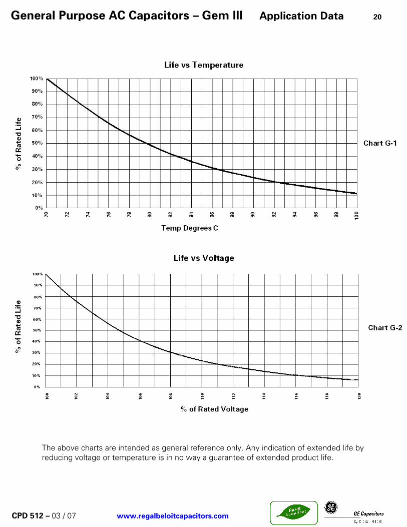
Life Vs Temperature
% of Chart G-1 Life
Degrees ˚C
Life Vs Voltage
% of Rated Chart G-2 Life
% of Rated Voltage
General Purpose AC Capacitors – Gem III Application Data 15
CPD 512 – 03 / 07 www.regalbeloitcapacitors.com
Percent Capacitance Vs Temperature
% Capacitance Chart E-3 Change
Temperature (Degrees ˚C)

General Purpose AC Capacitors – Gem III (Series Section) 16
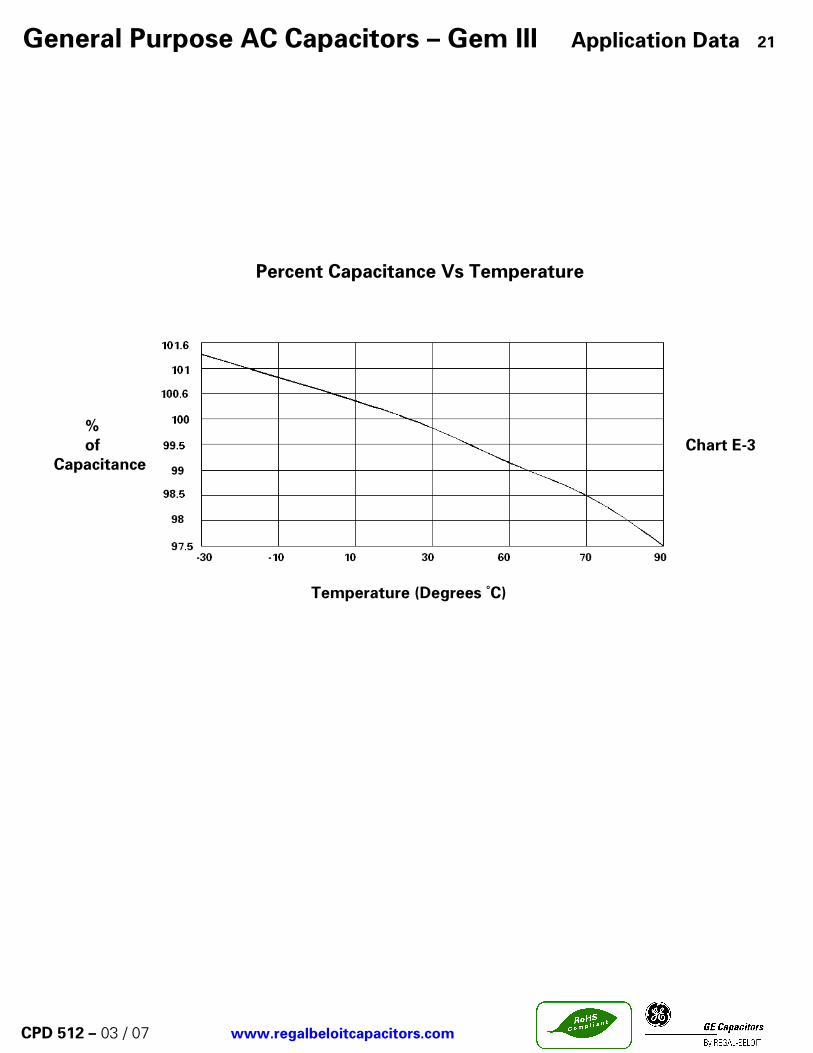
SPECIFICATIONS: Available Capacitance Range: 2 to 45 µF Capacitance Tolerance: ± 6% Capacitance Variation with Temperature: See chart E-3 on page 21. Rated Voltage: See Rating Tables. Rating is the 60Hz RMS voltage for a
sinusoidal waveform. For other waveforms refer to the Application Note on page 6.
Leakage Current: 30 µA maximum Frequency: 50/60 Hz. For higher frequencies refer to the Application Note. Operating Temperature: -40 ˚C to +70 ˚C Storage Temperature: -40 ˚C to +90 ˚C Operating Life: 60,000 hours with 94% survival Dissipation Factor: 0.1% maximum Case Material/Finish: Unpainted Aluminum Terminations: 0.250” x 0.031” quick connect blades. Dielectric Fluid: Dielektrol VI Internal Protection: UL recognized Pressure Sensitive Interrupter. See Ratings
Table for RBC’s Code Number listed under RBC’s UL. File E7793 (N). For UL submittals with these capacitors use the RBC ’Pxxx’ number not the Catalog Number. The corresponding generic UL designation that includes the Available Fault Current (AFC) rating is given below. All these capacitors are capable of interrupting available fault currents of up to 10,000 amperes.
Case Style RBC Code Generic UL Code
A P851 A10000AFC
B P852 B10000AFC
C P853 C10000AFC
CPD 512 – 03 / 07 www.regalbeloitcapacitors.com
660 Volts AC This series of Gem III is specifically designed for general-purpose AC applications in power supplies, UPS and power conversion equipment. Application Data is provided that gives the Equivalent Series Resistance (ESR) for each units. This allows the user to calculate the losses for each design/application and to ensure that they are kept within the permissible limits. Any questions regarding the suitability of a capacitor for a particular application may be referred to RBC Engineers through your RBC sales representative.

General Purpose AC Capacitors – Gem III (Series Section) 17
Capacitance (µµµµF)
Catalog Number Case StyleHeightC(in.)
ULCode
ESR ohms
Curve Number
2 27L6095 A 3.88 P851 0.0971 12.5 27L6093 A 3.88 P851 0.0984 23 27L6094 A 3.88 P851 0.0831 24 27L6012 A 3.88 P851 0.0639 25 27L6013 A 3.88 P851 0.0723 26 27L6014 A 4.75 P851 0.0615 37 27L6015 A 4.75 P851 0.0739 38 27L6016 A 4.75 P851 0.0657 410 27L6017 B 3.88 P852 0.0404 412 27L6018 B 4.75 P852 0.0366 415 27L6073 C 4.75 P853 0.0309 418 27L6089 D 3.88 P854 0.0361 420 27L6082 D 4.75 P854 0.0334 525 27L6022 D 4.75 P854 0.0294 530 27L6023 D 4.75 P854 0.0220 5
CPD 512 – 03 / 07 www.regalbeloitcapacitors.com
660 Volts AC
2003 Revision
Case Style a b
A 2.16 1.31
B 2.69 1.556
C 2.91 1.91
D 3.66 1.97

Application Note 18
CPD 512 – 03 / 07 www.regalbeloitcapacitors.com
27L Series 660 Volts AC (series section) The 27L series of capacitors on the attached product sheet may be used in AC applications where the voltage waveform is non-sinusoidal. This Application Note is provided to assist in the correct use of the capacitors where higher frequency harmonic currents are present. If you need further assistance please contact RBC’s Capacitor’s Operation through your normal sales channel. Higher frequency currents are commonly encountered in the filter circuits of static Power Converters. These frequencies range from 180 to 1500 Hz for a 60 Hz system in various combinations of the odd harmonics depending on the type of converter. Generally, there are not significant harmonic currents above the 25th harmonic. These capacitors can carry a total current of up to 15 amperes RMS (fundamental plus harmonics). The Equivalent Series Resistance (ERS) for each Catalog Number is shown in the ESR tables on this page. This value may be used to calculate the expected watts loss for a particular application. The user must determine the total RMS current (fundamental plus harmonics) for the application. The watts loss is then calculated using the equation:
W = I 2 x ESR
Where I = Total RMS current And ESR= Value from ESR tables. The calculated watts from this equation must not exceed the allowable watts loss shown on the curve corresponding to the particular capacitor. Two sets of curves are shown, one for natural circulation and one for forced air circulation.
NOTES
(1) In no case should the total RMS current of 15 amperes be exceeded for any of these capacitor
(2) Running the capacitors at case temperatures above 70 ºC will have a significant effect on expected life. (See chart G-1 on page 20)
(3) Running the capacitors at voltages above the nominal rated voltage will also result in significantly reduced life. (See chart G-2 on page 20)

Allowable Watts Loss - 27L (660 Volt) Series Section 19
CPD 512 – 03 / 07 www.regalbeloitcapacitors.com
Natural Circulation Maximum Allowable Watts Loss Ambient Temperature (ºC) – Natural Circulation
Allowable Watts Loss - 27L (660 Volt) Series Section
Forced Circulation Maximum Allowable Watts Loss
Ambient Temperature (ºC) – Forced Circulation
General Purpose AC Capacitors – Gem III Application Data 20
CPD 512 – 03 / 07 www.regalbeloitcapacitors.com
The above charts are intended as general reference only. Any indication of extended life by reducing voltage or temperature is in no way a guarantee of extended product life.
General Purpose AC Capacitors – Gem III Application Data 21
CPD 512 – 03 / 07 www.regalbeloitcapacitors.com
Percent Capacitance Vs Temperature
% of Chart E-3 Capacitance
Temperature (Degrees ˚C)

Capacitance µµµµF
CatalogNumber BASE HT
Capacitance µµµµF
CatalogNumber
BASE HT UL CODE
2.0 61L1271 A 2.12 2.0 27L6095 A 3.88 P8512.5 61L1280 A 2.88 2.5 27L6093 A 3.88 P8513.0 61L1272 A 2.88 3.0 27L6094 A 3.88 P8514.0 61L313 A 2.88 4.0 27L6012 A 3.88 P8515.0 61L1273 A 3.88 5.0 27L6013 A 3.88 P8516.0 61L1274 A 3.88 6.0 27L6014 A 4.75 P8517.0 61L316 A 3.88 7.0 27L6015 A 4.75 P8518.0 61L1275 A 4.75 8.0 27L6016 A 4.75 P85110.0 61L1286 B 3.88 10.0 27L6017 B 3.88 P85212.0 61L1276 B 4.75 12.0 27L6018 B 4.75 P85215.0 61L1289 B 5.75 15.0 27L6073 C 4.75 P85318.0 61L1277 B 5.75 18.0 27L6089 D 3.88 P85420.0 61L322 C 4.75 20.0 27L6082 D 4.75 P85425.0 61L323 C 5.75 25.0 27L6022 D 4.75 P85430.0 61L324 D 5.75 30.0 27L6023 D 4.75 P854
Capacitance µµµµF
CatalogNumber
BASE HTCapacitance
µµµµF
CatalogNumber
BASE HT UL CODE
2.0 26F6618 A 2.12 2.0 27L6095 A 3.88 P8512.5 26F6619 A 2.12 2.5 27L6093 A 3.88 P8513.0 26F6620 A 2.38 3.0 27L6094 A 3.88 P8514.0 26F6621 A 3.12 4.0 27L6012 A 3.88 P8515.0 26F6622 A 3.50 5.0 27L6013 A 3.88 P8516.0 26F6623 A 4.25 6.0 27L6014 A 4.75 P8517.0 26F6624 A 4.50 7.0 27L6015 A 4.75 P8518.0 26F6625 A 5.50 8.0 27L6016 A 4.75 P85110.0 26F6626 C 3.88 10.0 27L6017 B 3.88 P85212.0 26F6627 C 4.50 12.0 27L6018 B 4.75 P85215.0 26F6628 C 5.50 15.0 27L6073 C 4.75 P85318.0 26F6629 C 6.75 18.0 27L6089 D 3.88 P85420.0 26F6634 D 6.25 20.0 27L6082 D 4.75 P85425.0 26F6665 D 7.25 25.0 27L6022 D 4.75 P85430.0 26F6636 D 8.00 30.0 27L6023 D 4.75 P854
GEM II (61L) GEM III SERIES SECTION (27L)
Film/Paper (26F) GEM III SERIES SECTION (27L)
CPD 512 – 03 / 07 www.regalbeloitcapacitors.com
27L SERIES OUTLINE
61L SERIES OUTLINE
26F SERIES OUTLINE
A B
2.16 1.31
2.69 1.56
2.91 1.91
3.66 1.97
0.81
0.81
0.81
Base size
A
B
C
D
Dimensions
D
0.81
CROSS REFERENCE 600 VOLTS AC
26F6600 SERIES & 61L SERIES to NEW 27L SERIES 660 VAC
22

Dual Rated Capacitors 23
1000 Volts Peak This line of dual Rated AC/DC Capacitors is specifically designed for applications such as AC/DC filers where harmonic frequencies greater than 60 Hz are common. These capacitors are typically used in DC filters at voltages above those served by electrolytic type construction.
CPD 512 – 03 / 07 www.regalbeloitcapacitors.com
SPECIFICATIONS Available Capacitance Range: 3.0 to 50 µF Capacitance Tolerance: 97F ± 6% Capacitance Variation with Temperature: ± 5% from -40 ˚C to +70 ˚C Rated Voltage: See Rating Tables. Rating is Maximum Peak
DC Voltage. Ripple Voltage The RMS ripple voltage should not exceed the
following percentages of the rated voltage for these frequencies:
Frequency % of Rated Voltage 97F
60 Hz 44 120 Hz 30 400 Hz 12 1,000 Hz 8 10,000 Hz 0.6
Operating Temperature: -30 ˚C to +70 ˚C Storage Temperature: -55 ˚C to +70 ˚C Operating Life: 60,000 hours with 90% survival with proper derating. Dissipation Factor: 0.3% maximum Case Material/Finish: Aluminum Case (NO PAINT) Terminations: 97F (3) or (4) 0.250” x 0.031”inch quick connect
blades per terminal (see outline drawing). Dielectric Fluid: 97 F: Dielektrol VI Internal Protection: Pressure Sensitive Interrupter.

General Purpose DC Capacitors 24
*STANDARD RATINGS
Capac itance (µµµµF )
C a ta logN um ber
CaseS ty le
H e igh tC (in .)
3 .0 97F5437 A 2 .124 .0 97F5337 A 2 .885 .0 97F5339 A 2 .886 .0 97F5436 A 2 .887 .5 97F9036 A 3 .8810 .0 97F5300 A 3 .8812 .5 97F5001 P 2 .8815 .0 97F9037 P 2 .8817 .5 97F9038 P 3 .8820 .0 97F9039 P 3 .8825 .0 97F9040 P 4 .7530 .0 97F5023 P 4 .7535 .0 97F9041 S 4 .7540 .0 97F5116 S 4 .7545 .0 97F5209 T 3 .8850 .0 97F5211 T 3 .88
1000 V o lts P eak (440 V ac ,D ua l R a ted )
Case Style K JP 1.75 1.88S 2.00 2.12T 2.50 2.62
Case Style A Case Styles (97F Series) P, S and T
CPD 512 – 03 / 07 www.regalbeloitcapacitors.com

Case Style
Bracket Part Number
a b c
P 295A6016P31 1.75 1.12 1.31
S 295A6016P32 2.00 1.25 1.44
T 295A6016P33 2.50 1.50 1.69
Case Style
Bracket Part Number
d e
A 128A2244ACP21 2.69 3.13
B 128A2244ABP25 3.27 3.70
C 128A2244ABP22 3.44 3.88
D 128A2244ABP23 4.19 4.63
Case Style
Bracket Part Number
d e w t
A K9827065P21 2.56 2.94 0.50 0.02
B K9827065P31 3.06 3.50 0.63 0.02
C 614A301P61 3.31 3.81 0.75 0.03
D 614A301P51 4.06 4.56 0.75 0.03
P 279A7235P24 2.50 2.88 0.75 0.04
S 279A7235P22 2.75 3.12 0.75 0.04
T 279A7235P23 3.25 3.62 0.75 0.04
25
CPD 512 – 03 / 07 www.regalbeloitcapacitors.com
UNIVERSAL WRAP AROUND BRACKETS ROUND CASE STYLES
UNIVERSAL WRAP AROUND BRACKETS
OVAL CASE STYLES (2) .156 dia holes suplplied with
# 6-32 screw and nut
WRAP AROUND BRACKETS ROUND AND OVAL CASE STYLES
Mounting Hardware for GEM III Capacitors

Case Style
d e
A 2.56 3.00
2.12 302C920P210 B 3.13 3.56
2.88 302C920P113 C 3.38 3.81
3.88 302C920P115 D 4.13 4.56
4.75 302C920P116
5.75 302C920P209 P 2.33 2.76
S 2.57 3.00
T 3.07 3.50
CaseHeight
Bracket Part Number
614A527P21 60 0C
178A3744P21 105 0C
Temperature RatingBoot Part Number
26
CPD 512 – 03 / 07 www.regalbeloitcapacitors.com
FOOTED BRACKETS
.187
PROTECTIVE BOOT PROTECTIVE CAP
Mounting Hardware for GEM III Capacitors

CPD 512 – 03 / 07
Publication Description Replaces
CPD-510 AC Motor Run Capacitors CPD-501
CPD-511 AC HID Lighting Capacitors CPD-501
CPD-512 General Purpose Capacitors CPD-501
CPD-517 Power Electrolytic Capacitors (General) New Pub.
AVAILABLE RBC COMPONENT CAPACITOR PUBLICATIONS
Please contact your RBC Sales Representative for further information Call or write directly to,
GE Capacitors by Regal Beloit 11970 PELLICANO DR. , SUITE 300 EL PASO ,TEXAS 79936 USA Telephone: (915) 849-5757, (915) 849-5758 Fax: (915) 849-5799