can e autosar - chalmers publication library...
TRANSCRIPT

Chalmers University of Technology University of Gothenburg Department of Computer Science and Engineering Göteborg, Sweden, April 2011
XCP OVER CAN AND ETHERNET ON AUTOSAR
Calibration and Measurement Protocol
Master of Science Thesis in Computer Science and Automation and Mekatronics
Joakim Plate
Peter Fridlund


Chalmers University of Technology University of Gothenburg Department of Computer Science and Engineering Göteborg, Sweden, April 2011
The Author grants to Chalmers University of Technology and University of Gothenburg the non-exclusive right to
publish the Work electronically and in a non-commercial purpose make it accessible on the Internet.
The Author warrants that he/she is the author to the Work, and warrants that the Work does not contain text, pictures
or other material that violates copyright law.
The Author shall, when transferring the rights of the Work to a third party (for example a publisher or a company),
acknowledge the third party about this agreement. If the Author has signed a copyright agreement with a third party
regarding the Work, the Author warrants hereby that he/she has obtained any necessary permission from this third
party to let Chalmers University of Technology and University of Gothenburg store the Work electronically and make it
accessible on the Internet.
XCP over CAN and Ethernet on AUTOSAR Calibration and Measurement Protocol
J. Plate, P. Fridlund, © Joakim Plate, April 2011. © Peter Fridlund, April 2011. Examiner: Rolf Snedsböl Chalmers University of Technology University of Gothenburg Department of Computer Science and Engineering SE-412 96 Göteborg Sweden Telephone + 46 (0)31-772 1000 Cover: The McLaren Formula One team monitoring the car’s embedded systems before the start of the race. Department of Computer Science and Engineering Göteborg, Sweden April 2011


i
Abstract
New vehicles contain more and more electronic aides and control systems. As the number of
functions increase, the complexity of the system increases at an even greater pace. AUTOSAR is an
initiative that aims to bring order to embedded electrical systems in vehicles.
The ever larger software systems naturally generate ever larger amounts of data needing to be taken
care of, analysed and checked for correctness during the development of the system itself. XCP is a
network protocol that is mainly used for transferring measurement data and calibration parameters
during the development process in the automotive industry. In order to utilize the complete capacity
of the existing in-vehicle network, the protocol has been designed to be independent of the
transport layer.
The aim of this thesis is to implement a subset of XCP for execution on a rapid prototyping platform
developed by QRtech, a high-tech consulting company in Kallebäck, Gothenburg. In order to be
compatible with the latest technology and methodology XCP has been implemented according to the
requirements specified by AUTOSAR.
In the current implementation, all the mandatory requirements are met, have been verified and
comply with the AUTOSAR standard. Even before completion, the project roused interest in parts of
the local automotive industry.
Keywords: XCP, AUTOSAR, CAN Network, Ethernet, Measurement and Calibration, DAQ-list, QR5567.


iii
Sammanfattning
Nya fordon innehåller allt mer elektroniska hjälpmedel och styrsystem. I takt med att funktionerna
blir fler och fler ökar komplexiteten hos systemet lavinartat. AUTOSAR är ett initiativ för att försöka
skapa ordning inom de inbyggda fordonselektriska systemen. Genom att skapa standardiserade
gränsytor mellan alla de funktionella applikationsdelarna och de hårdvarunära delarna är tanken att
systemet ska vara skalbart och därmed undviks problemet med sambandet mellan komplexitet och
storlek.
De allt större mjukvarusystemen generar naturligtvis också mer och mer datatrafik som måste kunna
läsas och övervakas under framtagningen av systemet. XCP är ett nätverksprotokoll som i huvudsak
används för att överföra mätdata och kalibreringsparametrar vid utvecklingsarbete inom bilindustrin.
För att på ett enkelt och smidigt sätt kunna utnyttja hela bilens existerande inbyggda
nätverkskapacitet är protokollet designat för att vara oberoende av vilket transportmedia som
används.
Målet för examensarbetet är att implementera utvalda delar av XCP protokollet för exekvering på en
prototyputvecklingsplattform framtagen av QRtech, ett teknikkonsultföretag i Kallebäck i Göteborg.
För att var kompatibelt med de senaste teknikerna och metodikerna så har XCP implementerats
enligt de krav som AUTOSAR specificerar.
Som implementationen ser ut idag är samtliga XCP – och AUTOSAR specifika krav uppfyllda, och
verifierade. Även före fullbordandet visades visst intresse från lokala aktörer inom bilindustrin.

iv

v
Preface
We would like to thank the following people for aiding us during this thesis project:
Rolf Snedsböl our examiner who has provided us with a lot of suggestions and corrections of this
report.
Olof Bergqvist for his tutoring, for taking care of a sizeable amount of red-tape duties in connection
to our thesis.
Johan Ekberg for help with the Arctic Core AUTOSAR platform.
Björn Siby and Alborz Sedaghat for helping us with the initial steps of the project and lending us their
thesis to use as reference.
Erik Larsson for input on the functionality of the QR5567.
The unnamed lady who every morning brought us breakfast at the office.
Finally we would like to thank all the fine men and women at QRtech for their moral support and for
making us feel welcome and at home at QRtech.

vi

vii
Table of Contents
1 Background .............................................................................................................................................. 1 1.1 Previous work .................................................................................................................................. 1 1.2 Purpose ........................................................................................................................................... 1 1.3 Significance ...................................................................................................................................... 2
2 Scope ....................................................................................................................................................... 3 2.1 Limitation of Transport Protocols ..................................................................................................... 3 2.2 Optional XCP features ...................................................................................................................... 3
3 AUTOSAR platform ................................................................................................................................... 5 3.1 Layered infrastructure ...................................................................................................................... 5
3.1.1 Basic Software Layer ................................................................................................................ 5 3.1.2 Runtime Environment .............................................................................................................. 9 3.1.3 Application Layer ..................................................................................................................... 9
3.2 Open Standard Cross car manufacturers ......................................................................................... 10 3.3 Standardized API for application modules ....................................................................................... 11 3.4 Drawbacks with AUTOSAR .............................................................................................................. 12
4 XCP - Calibration & Measurement Protocol ............................................................................................. 13 4.1 Mode of operation ......................................................................................................................... 13 4.2 Transport Layer (Ethernet, CAN, USB) ............................................................................................. 14
4.2.1 Ethernet ................................................................................................................................ 14 4.2.2 CAN ....................................................................................................................................... 14 4.2.3 USB ....................................................................................................................................... 16
4.3 Online Calibration .......................................................................................................................... 16 4.4 DAQ Lists – Data Acquisition Lists ................................................................................................... 17
4.4.1 DAQ-list configuration............................................................................................................ 18 4.4.2 STIM Lists – Data Stimulation Lists ......................................................................................... 19 4.4.3 Processing Event Channel ...................................................................................................... 20
4.5 Bypassing ....................................................................................................................................... 20 4.6 Flashing / Firmware upload ............................................................................................................ 20 4.7 Security – Seed & Key ..................................................................................................................... 21
5 Development Environment ..................................................................................................................... 23 5.1 Arctic Core ..................................................................................................................................... 23 5.2 Arctic Studio................................................................................................................................... 23 5.3 MinGW .......................................................................................................................................... 24 5.4 Vector CANape ............................................................................................................................... 24 5.5 QR5567 .......................................................................................................................................... 27 5.6 Vector CANcaseXL .......................................................................................................................... 28
6 Development Process ............................................................................................................................. 29 6.1 Basic Protocol Infrastructure .......................................................................................................... 29 6.2 Development of testing tools ......................................................................................................... 30
7 Result ..................................................................................................................................................... 31 7.1 AUTOSAR Integration of the XCP module ........................................................................................ 31 7.2 Code Organization .......................................................................................................................... 32 7.3 Memory Abstraction ...................................................................................................................... 34 7.4 Demo Application........................................................................................................................... 34
8 Discussion .............................................................................................................................................. 35 8.1 Implementation ............................................................................................................................. 35 8.2 The AUTOSAR initiative .................................................................................................................. 35 8.3 Future Work ................................................................................................................................... 36
9 References ............................................................................................................................................. 37 Appendix A – Thesis proposal ........................................................................................................... Appendix - 1 Appendix B – Time plan.................................................................................................................... Appendix - 3 Appendix C – Readme for XCP AUTOSAR module ............................................................................. Appendix - 5

viii

ix
Acronyms
ADC API
ASAM AUTOSAR
BSW
Analog Digital Converter Application Programming Interface Association for Standardization of Automation and Measuring Systems Automotive Open System Architecture Basic Software
CAN CCP
Controller Area Network CAN Calibration Protocol
CTO Control Transmission Object DAQ DIO
Data Acquisition List Digital Input Output
DTO ECU E/E
GDB GNU
MCAL ODT
PEEDI PWM
Data Transmission Object Electronic Control Unit Electrics and Electronics GNU Debugger GNU’s Not Linux Microcontroller Abstraction Layer Object Descriptor Table Powerful Embedded Ethernet Debug Interface Pulse Width Modulator/Modulation
RTE Run-Time Environment SWC STIM TFTP USB VFB
Software Component Data Stimulation List Trivial File Transfer Protocol Universal Serial Bus Virtual Function Bus
XCP Universal Measurement & Calibration Protocol

1
1 Background Vehicles are becoming increasingly more computerized with up to 90% of all new functionality falling
into the E/E (Electrics/Electronics) category. As a result it is becoming progressively harder to
maintain an overview of the E/E system in a vehicle. To counter this, the industry has united in an
effort to create a single software architecture that can be followed by everyone from car
manufacturers to suppliers of components and creators of tools. This initiative is known as AUTOSAR
(Automotive Open System Architecture).
Because of the increasing amount of electronics and the amount of data traffic that they generate,
the need to transfer larger amounts of data has arisen. For this purpose a special network protocol
called XCP (Universal Measurement and Calibration Protocol) has been conceived and specified.
Because it has the capability to run on different transport mediums it can utilize more of the
technological progress that has been made within the automotive E/E area. As the name ‘XCP’
suggests, the protocol is an evolutionary continuation of CCP (CAN (Controller Area Network)
Calibration Protocol), where the ‘C’ for ‘CAN’ has been replaced by ‘X’ to indicate an unknown or
generic transport layer implementation. CCP was developed largely by ASAM (Association for
Standardization of Automation and Measuring Systems), a consortium of German car manufacturers
founded in 1998 that provides standards for data models, interfaces and syntax specifications for
various uses, such as testing, simulation and evaluation. These standards are adhered to mainly by
European car makers and to a lesser extent by the Japanese and American ditto.
1.1 Previous work QRtech (Qualified Real-time technology) is an independent company that has their own in-house
developed embedded prototyping platform called the QR5567. Its purpose is to be used for
advanced engineering projects, mainly in the automotive area. Previous work at the company in
regards to the QR5567 platform has consisted of implementation of necessary software
infrastructure, such as start-up routines and programming tools.
1.2 Purpose The purpose of this project is to make a ‘Universal Measurement and Calibration Protocol’ (XCP)
implementation that complies with the AUTOSAR XCP module specification. This implementation is
to be run on the Arctic Core AUTOSAR platform targeting the rapid prototyping board QR5567. The
main communication protocols of interest are CAN (Controller Area Network) and Ethernet. The
module should not be specific to a single embedded component, but be adaptable to different
applications of embedded components. Since the size of the project is not fully known by QRtech,
part of the task is to define which optional components of the protocol to include (see Appendix A
for further details).

2
1.3 Significance Having a standardized protocol for measurement and calibration allows for reusability of toolkits
between different hardware and software vendors. A generic module for XCP with a configurable
feature set eliminates the need for reimplementation of the protocol for each use case. Making it
AUTOSAR compatible widens the area of use. For a company in the automotive sector of today, it is
vital to be able to offer the latest technological solutions and to have staff with the right
competence. As the industry surges forward towards the common AUTOSAR platform, expertise in
the field becomes more and more sought after.

3
2 Scope Implementing XCP in its entirety is a considerable task, too large to fit within the given timeframe for
this project. Some features and functionality had to be excluded in order to ensure completion (see
Appendix B). The following goals were set from the beginning:
Selecting which XCP services to implement
Implementing the selected XCP services
Verifying the implementation
2.1 Limitation of Transport Protocols XCP can be run on a number of different transport-layer protocols; the initial request from QRtech
was to make an implementation for CAN (Controller Area Network) and for Ethernet. As work
progressed it was discovered that some AUTOSAR modules necessary for an Ethernet
implementation were not yet in place in Arctic Core. As a result Ethernet became of secondary
importance. For development purposes an Ethernet version was implemented, because the
possibility to test functionality without the need of reprogramming the device each time was
considered worth the extra time and effort. The assumption was that it would prove worthwhile in
the end, especially if the system would live on after the project was completed. It has however not
been tested or verified while running on the target hardware and must therefore be considered as
out of the project scope. If or when the necessary Ethernet modules in Arctic Core are implemented,
XCP for Ethernet could probably be adapted quite easily.
2.2 Optional XCP features XCP contains many features that are not strictly necessary in order to run the core functionality.
Because of limited knowledge of time requirements for the various implementations, an open
planning scheme was adopted. Instead of defining what to include or exclude, a prioritization order
was made, adding optional features if time allowed. The prioritization was revised after input-
meetings with QRtech management as depending on what other projects the company was running
at the same time, the possible areas of application might vary.


5
3 AUTOSAR platform More and more of the added value in vehicles falls within the electrics and electronics (E/E) area.
Traditionally the way to develop E/E in vehicles is to have one unit for every service. Because of the
increase in the number of services and the subsequent increased architectural complexity, E/E
systems are becoming increasingly difficult to manage. This difficulty is of course also associated with
higher costs for both further development and maintenance of the system already in place. In an
effort to tackle this problem and move away from the ‘one box, one service’ mentality, a completely
new approach was needed. Several automotive companies have decided to unite and develop a
common platform. This initiative is known as AUTOSAR. The aim is to revolutionize the way
automotive software is developed and also the way in which it is executed on the ECUs in the vehicle.
The AUTOSAR consortium stipulates the goal of the initiative as follows:
“The primary goal of the AUTOSAR development cooperation is the standardization of
basic system functions and functional interfaces, the ability to integrate, exchange and
transfer functions within a car network and to substantially improve software updates
and upgrades over the vehicle lifetime. Having this goal in mind, AUTOSAR pushes the
paradigm shift from an ECU based to a function based system design attempt in
automotive software development and enables the management of the growing E/E
complexity with respect to technology and economics.” – FAQ on AUTOSAR.org
By decoupling hardware and software the AUTOSAR consortium hopes to make development more
independent. As a way to assist this it was decided that the platform should handle all ECU access.
This has the effect that a developer does not need specific knowledge about the ECU. (1)
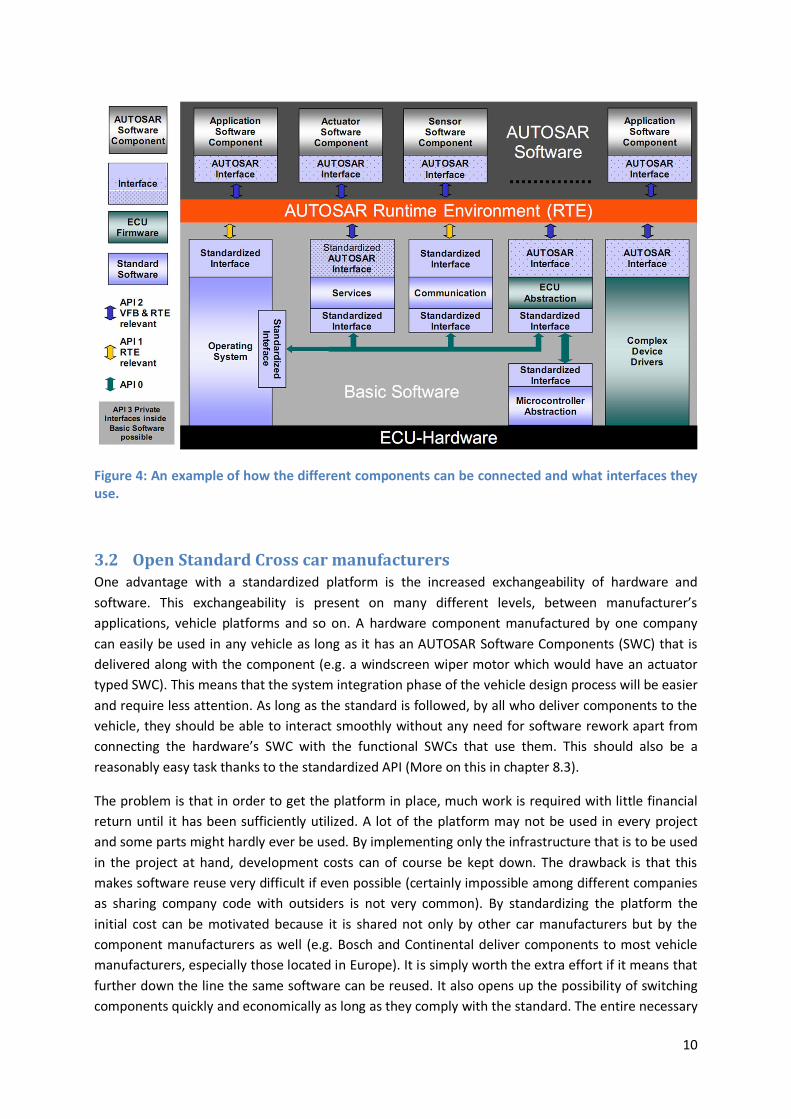
3.1 Layered infrastructure In order to provide an easy-to-read top-down description, the AUTOSAR platform has layered
software architecture. It maps the basic software modules to the appropriate layers and shows their
relationship. There are three main layers in the AUTOSAR software architecture, each with their own
well defined purpose (see Figure 1 and Figure 3).
3.1.1 Basic Software Layer
The bottom layer is the Basic Software Layer (BSW). This is the only layer that can access the
Microcontroller itself. It consists of a number of modules which are used by the Application layer via
the Runtime Environment (RTE). Each module has an AUTOSAR specification that specifies the
modules requirements, its data types and interfaces. The modules are grouped into the following sub
layers:

6
Micro Controller Abstraction Layer (MCAL) – Contains internal drivers that have access to the
microcontroller and internal peripherals. The MCAL makes the higher software layers
independent of the microcontroller. This means that if for some reason the microcontroller
needs to be replaced, the rest of the system can be left as it is. The only changes that are
needed are to those modules concerning the MCAL. The modules of the MCAL are divided in
to four different blocks (see Figure 2):
o The Microcontroller drivers block consists of four drivers; the General Purpose Timer,
the Watchdog Driver, the MCU driver and Core Test.
o The Memory Drivers block contains drivers which provide services for memory
handling, such as reading from, writing to or simply erasing memory devices. In
terms of memory devices, the AUTOSAR standard supports internal and external
Flash memory and internal EEPROM (Electrically Erasable Programmable Read-Only
Memory).
o The Communication Drivers block contain drivers for the different methods of
communication supported in AUTOSAR such as CAN FlexRay and Ethernet (in
AUTOSAR 4.0).
o I/O Drivers block contain drivers for input and output modules, such as PWM (Pulse
Width Modulation) and ADC (Analog Digital Converter).
Figure 1: Schematic view of the different architecture layers including the sub layers in the BSW layer.

7
ECU Abstraction Layer - Makes the higher software layers independent of the hardware
layout of the ECU. In order to achieve the desired independence the layer is divided into five
blocks in an attempt to mimic an ECU.
o The I/O Hardware Abstraction provides functionality for handling input and output to
the system. This is the only block in the ECU abstraction layer that has access to the
RTE directly, instead of through the system layer as is the case for the other blocks in
the layer.
o The Communication Hardware Abstraction is a collection of interfaces for each of the
communication techniques of an AUTOSAR compliant ECU. These interfaces abstract
the drivers for the specific communication technique and provide the upper layers
with transmission functionality such as status information and send/receive-
functions. Instead of having direct access to microcontroller hardware, the
equivalent MCAL driver is used.
o The Memory Hardware Abstraction is in function a lot like the communication
hardware abstraction. It provides the upper layer with functionality required to
access memory via the MCAL drivers.
o The Onboard Device Abstraction is used for any devices that do not fit in anywhere
else. The access to these devices is routed through the MCAL.
o Any components that are not in the AUTOSAR specification but still need to access
the hardware falls into the Complex Driver Layer. It provides the possibility to add
extra functionality such as device drivers; some might argue that this isn’t strictly
part of the ECU abstraction layer.
Figure 2: The modules of the MCAL layer divided into blocks.

8
Services Layer – Provides services such as memory and OS functionality for the other BSW
modules and the application layer.
o The System Services module contains the AUTOSAR OS (Operating System) which
handles scheduling and run-time resource protection and offers reasonable real-time
performance. It is the scheduling functionality in the OS that executes the upper
layer software components via the tasks that they are mapped to.
o Communication Services provides the necessary functionality in order to run the
vehicle network communication. This is done by providing an interface to the
different vehicle techniques such as CAN and FlexRay, along with network
management and diagnostics. This includes reworking the message frames and
omitting transport layer specific data such as message headers and other various
properties (hardware timestamps for example).
o Memory Services consists of modules which are responsible for managing all non-
volatile data. The purpose of the memory service block is to provide non-volatile
data to upper layer applications in a uniform and well defined way, abstract memory
from the corresponding locations and properties relevant to the application. It also
provides mechanisms for saving, loading, for checksum protection and for
verification.
Figure 3: A selection of modules organized into layers (colors) and blocks (large boxes).

9
3.1.2 Runtime Environment
The RTE is responsible for mapping the components in the application layer and the basic software
layer so that they can communicate and make use of each other’s functionality. The way this is done
in AUTOSAR is through the concept of ports. A port is either of type providing or requiring. A
providing port in AUTOSAR is realized as an implemented function while a requiring port is realized
as a function call. The ports can be configured in one of two ways; either as a sender-receiver
interface or as a client-server interface. Depending on which interface is used and how it is
configured the behaviour of the RTE may vary. If for instance a requiring port interface is configured
as asynchronous the RTE will not block in order to call the providing port, instead it will schedule the
call at a more convenient time and continue execution.
At the design level the RTE is abstracted to a Virtual Function Bus (VFB) through which all
communication runs. This also alleviates the communication handling for application layer
development. In a way the RTE is the heart of the architecture, the glue that binds all the other
components. Since the entire system is not fully known at the time when the RTE is being developed
some parts of it must be generated afterwards. This is done when the system is configured, i.e. when
all the different components are known and their descriptions have been made. A schematic view of
the connections the RTE provides is seen in Figure 4
3.1.3 Application Layer
The top layer is the application layer that consists of software components that provide various
functionalities and services in the vehicle. The two most significant types are the application software
component type and the sensor actuator type. The latter is a software representation of a hardware
component (a sensor or an actuator) while the former can make use of sensor data to provide
actuators with relevant input. The data that is sent to or received from application layer components
use the port interface functionality as described in 8.1.2.
It is the development of application layer software components that the whole AUTOSAR initiative is
based around and that justify its existence. The lower layers and the RTE have, in essence, the
purpose of making the development of application layer software components easier and
standardizing the development of said software components. Everything that uses the AUTOSAR
platform is located in the application layer; this is the part of the system where the components
actually do something useful in the vehicle.
10
3.2 Open Standard Cross car manufacturers One advantage with a standardized platform is the increased exchangeability of hardware and
software. This exchangeability is present on many different levels, between manufacturer’s
applications, vehicle platforms and so on. A hardware component manufactured by one company
can easily be used in any vehicle as long as it has an AUTOSAR Software Components (SWC) that is
delivered along with the component (e.g. a windscreen wiper motor which would have an actuator
typed SWC). This means that the system integration phase of the vehicle design process will be easier
and require less attention. As long as the standard is followed, by all who deliver components to the
vehicle, they should be able to interact smoothly without any need for software rework apart from
connecting the hardware’s SWC with the functional SWCs that use them. This should also be a
reasonably easy task thanks to the standardized API (More on this in chapter 8.3).
The problem is that in order to get the platform in place, much work is required with little financial
return until it has been sufficiently utilized. A lot of the platform may not be used in every project
and some parts might hardly ever be used. By implementing only the infrastructure that is to be used
in the project at hand, development costs can of course be kept down. The drawback is that this
makes software reuse very difficult if even possible (certainly impossible among different companies
as sharing company code with outsiders is not very common). By standardizing the platform the
initial cost can be motivated because it is shared not only by other car manufacturers but by the
component manufacturers as well (e.g. Bosch and Continental deliver components to most vehicle
manufacturers, especially those located in Europe). It is simply worth the extra effort if it means that
further down the line the same software can be reused. It also opens up the possibility of switching
components quickly and economically as long as they comply with the standard. The entire necessary
Figure 4: An example of how the different components can be connected and what interfaces they use.

11
infrastructure is already in place and it should, in theory, just be a matter of snapping the new
component (both hardware and software) into place.
In short; by using a standardized platform the automotive industry can; ‘Cooperate on standards,
compete on implementation’ which has become something of a motto for the AUTOSAR initiative. If
integration and infrastructure costs, both in terms of dollars & cents and man-hours, can be reduced
the amount left for implementing functionality will be much greater than otherwise. This in turn will
mean more functionality and/or higher quality software in terms of robustness, security and
dependability.
3.3 Standardized API for application modules In order to achieve some of the goals with the AUTOSAR initiative, standardization of basic system
functions and functional interfaces, a standardized API is almost unavoidable. The AUTOSAR
Application Programming Interface (API) defines all the functions and methods that are needed in
order to utilize the AUTOSAR platform’s functionality (see Figure 5). By following the structure and
naming conventions of the API, developers can make their code compatible with it making it easier
for other developers to use the functions implemented. The point is to ensure that all the different
AUTOSAR implementations are compatible with one another. As a result there is no need for
adaptation to OEM specific environments simply because there are none. If you know how to
connect to the AUTOSAR interfaces you have all the knowledge needed to integrate the component
to the system in question.
Figure 5: An example from the AUTOSAR API.
12
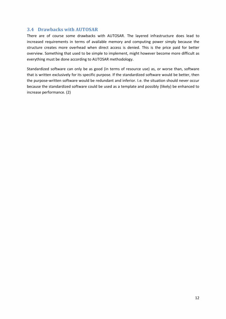
3.4 Drawbacks with AUTOSAR There are of course some drawbacks with AUTOSAR. The layered infrastructure does lead to
increased requirements in terms of available memory and computing power simply because the
structure creates more overhead when direct access is denied. This is the price paid for better
overview. Something that used to be simple to implement, might however become more difficult as
everything must be done according to AUTOSAR methodology.
Standardized software can only be as good (in terms of resource use) as, or worse than, software
that is written exclusively for its specific purpose. If the standardized software would be better, then
the purpose-written software would be redundant and inferior. I.e. the situation should never occur
because the standardized software could be used as a template and possibly (likely) be enhanced to
increase performance. (2)

13
4 XCP - Calibration & Measurement Protocol XCP is a generalization of a similar protocol called CCP with clear
separation between transport layer and protocol layer. Whereas CCP was
developed to support only CAN communication, its successor, XCP was
designed to support a wide range of transport protocols. XCP was
standardized by ASAM (Association for Standardization of Automation and
Measuring Systems) (3) (4)
Both XCP and CCP have their roots in the need for calibrating
Engine/Electronic Control Units (ECU) on the fly during the development
phase of their lifespan. Today’s vehicle control units often use quite
complex internal algorithms to calculate output from any given input. The
algorithms are more often than not parametric in that they have static
controlling parameters to adjust the behaviour of a standard algorithm. A
common day example of this could be the Traction Control Systems (TCU)
and Anti-lock brake systems (ABS) of your normal car. The algorithms used
in these types of system use input from various actuators (gyros,
accelerometers, speed, steering angle and so on) to control the brakes
and engine torque to avoid wheel lock and the car skidding out of control.
To keep costs down and to ensure proper behaviour, the algorithms used
to do these types of controls are standardized and often identical between
different models/manufactures of cars. To cope with the differences
between vehicles (weight, wheelbase, tires, engine etc) the algorithms can
be tuned through parameters. (5)
During the development process, a model of the vehicle is normally used
to tune the algorithm at the start, but eventually you are forced to tune
the controller when it is actually controlling the vehicle/system. This is
where XCP (and its predecessor CCP) comes in. It allows communication
over standard communication protocols like CAN/Ethernet/USB with the
ability to accurately measure and modify variables in the running
controller.
Figure 6 depicts the basic flow of command execution of the core XCP protocol.
4.1 Mode of operation XCP is designed as a Single Master/Multi Slave system. A single master system, on a development PC,
can be connected to multiple slaves running on embedded devices. This allows a complete view of a
larger controlled system. An example situation could be in a vehicle where a single master is
connected to the ECU handling engine control as well as another ECU controlling adaptive
suspension. The master controller is then able to measure internal controller states, as well as tune
parameters for the embedded system while evaluating performance.
Figure 6: Flow chart of the XCP protocol
Startup
Received Connect?
No
Received Command?
No
Process Command
Command Processing
Command Processing
Send Reply

14
4.2 Transport Layer (Ethernet, CAN, USB) The XCP protocol was designed from the ground up to be transport layer agnostic and as such can
support many different types of transport protocols. While each transport protocol puts some
restrictions on the core protocol, it functions according to the same principles and with the same
core packet syntax.
The XCP communication protocol is defined to use the slave’s native byte-order. This implies that the
master must be able to control two sets of byte orders for the XCP core protocol, but also simplifies
the implementation of the slave. The byte-order the slave uses is sent as a reply to the master when
the master connects to the slave for the first time.
The transport protocol sets limits on the possible throughput of data. A CAN network for example
has a limit of 1 mbit transfer rate, this however is only possible with no other bus load and can be
significantly lower if longer transmission cables are required. With Ethernet and USB this
transmission cap is lifted and much larger throughput is possible. This allows for high speed sampling
of large amount of data, while on a CAN network you may need to limit sampling speed and quantity
to not overload the protocol.
4.2.1 Ethernet
XCP over Ethernet frames each core XCP packet with a header containing a packet number and
length, but otherwise makes no changes to the underlying XCP core frame (see Figure 7). It allows for
transport over both TCP and UDP where UDP imposes a limitation of packet size (DTO1/CTO2) defined
by the maximum packet size of UDP. (4)
4.2.2 CAN
The CAN-bus (Controller-area network) is a serial communication bus originally constructed for
communication between microcontrollers in automotive applications. It is a multi-master broadcast
system without need for a controlling host computer. It has built in prioritization of messages with
minimal delay in transmission and reception.
1 DTO: Data Transfer Object
2 CTO: Control Transfer Object
Figure 7: Header and Tail for XCP on Ethernet.

15
When the CAN-bus is free, any node on the bus is free to start transmitting. If two nodes start
sending at the same time, the message with highest priority will be received by all nodes. The node
transmitting the lower priority message will resend its message after a given delay. Priority of
messages is defined by the message id, where a lower id has a higher priority than a numerically
higher id.
The automatic prioritization of messages functions through a method of recessive and dominant bits.
Where a logical 0 is considered dominant and a logical 1 is considered recessive. At the start of each
transmission, nodes send their identifier starting with the most significant bit. After transmitting a
recessive bit (1) on the serial bus, the node checks if the transmitted bit matches what is currently
received on the bus. Should any other node have transmitted a dominant bit at the same time, the
node will detect a dominant bit on the bus and stop transmission. After the full identifier has been
transmitted, only one node will remain active on the bus and can begin sending its payload.
XCP over CAN limits packet size (DTO/CTO) to 8 bytes, but allows for transfer of data without
identifier by leaving that up to the CAN packet identifier. The normal XCP frame over CAN can be
seen in Figure 8. Interleaved communication3 is not allowed. Each slave has at least two CAN id’s
reserved, one for receiving commands and one for sending. (4)
The XCP protocol has one extension when used over CAN which allows for automatic discovery of
connected XCP slaves on the CAN-bus. If the master broadcasts a GET_SLAVE_ID message on the
CAN-bus, all connected slaves will reply with a message signalling on which CAN packet id’s they
communicate.
3 Interleaved Communication: allows the master to send multiple commands to the slave without waiting for it
to acknowledge them.
Figure 8: Header and Tail for XCP on CAN.

16
4.2.3 USB
XCP over USB frames each core XCP packet with a header containing data length and an optional
packet number as can be seen in Figure 9. It also appends a tail which ensures that the following XCP
packet follows a defined alignment. The communication model allows for either single XCP packets
per USB packet, multiple complete packets in a single USB packet or streaming of XCP packets which
allows XCP packets to cross USB packet borders. (4)
Depending on the chosen method of packaging of XCP packets in USB packets, XCP may be limited to
the maximum size of an USB packet.
4.3 Online Calibration Provides direct read and write access to memory of the ECU. It also allows for access of different
memory areas with a XCP specific address extension. Each calibration segment of the devices may be
divided into multiple pages. Each page is semantically identical in the device but allows the master to
modify multiple parameters without them taking direct effect. When finished it can signal a page
switch for the embedded device where it starts using all of the newly written parameters at the same
time.
Each segment in the device has one ECU active page and one XCP active page. The page active for the
ECU is the memory the ECU is currently using for its internal control loops. The XCP page is the
memory area which the XCP master currently can read and write to. If the slave device allows it, the
XCP and ECU may point to the same memory in which case modifications take effect directly.
Figure 9: Header and Tail for XCP on USB

17
4.4 DAQ Lists – Data Acquisition Lists A core feature of the XCP protocol is the DAQ lists. In order to be able to send a large amount of data
in a small amount of time and with low bandwidth load desirable, XCP offers the ability to configure
lists that take care of transmitting requested data at a given interval. Each DAQ list (Figure 10) has a
number of Object Descriptor Tables (ODTs) that in turn contains Object Descriptor Table Entries (ODT
Entries) as described in Figure 11. Each ODT Entry has an address and a length, these make out the
description of the parameter that it represents. When the DAQ list is processed the contents of the
list is copied to the corresponding address of each entry in each ODT. The slave doesn’t receive an
acknowledgement that the master has received the data correctly.
Figure 10: For each DAQ-list configurations a number of ODT’s are defined, each having a unique identifying PID.
Figure 11: Each ODT entry in a DAQ list points to a memory element with specified address and length.
18
4.4.1 DAQ-list configuration
XCP has two different ways of configuring the DAQ-lists, static and dynamic. While static
configuration is mandatory according to the specification, dynamic configuration seems to be the
preferred way (as an example CANape only uses dynamic configuration in their examples). Which
configuration method that is to be used is decided exclusively by the slave, there is no way for the
master to request one or the other, nor can both be used in parallel. In addition to the configurable
DAQ-list (static or dynamic) the slave can also have a number of predefined DAQ-lists. These lists
cannot be altered in any way. Each ODT entry has a predefined address and size. The only thing the
master is allowed to do is configure their direction, prescaler, priority and which event channel it
should be connected to.
In static configuration the slave already has a structure of DAQ-lists with ODT’s and the ODT’s have
entries. This configuration cannot be edited. If there is only one DAQ-list, that has three ODT’s and
the ODT’s have 5 entries each, then this is all the master has got at its disposal. The entries can be
edited, i.e. the address and address extension that maps it to a memory space can be changed. A lot
of the DAQ-list’s properties can also be changed just as in the case with the predefined list.
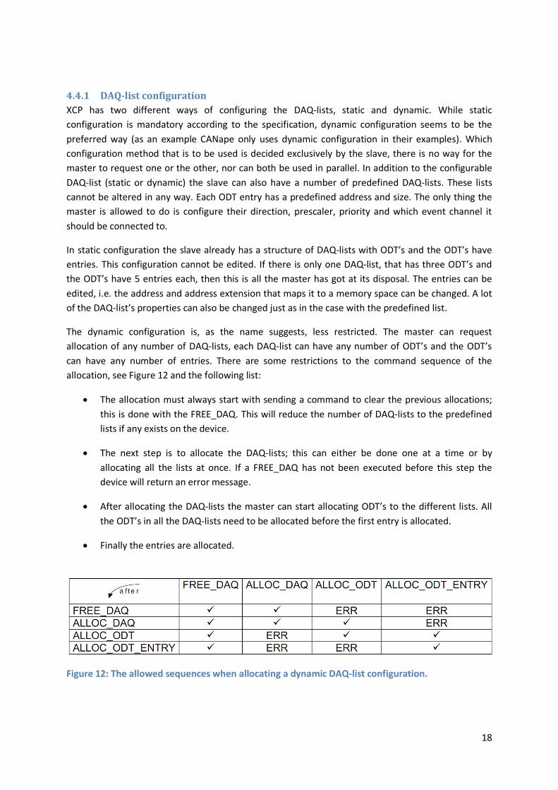
The dynamic configuration is, as the name suggests, less restricted. The master can request
allocation of any number of DAQ-lists, each DAQ-list can have any number of ODT’s and the ODT’s
can have any number of entries. There are some restrictions to the command sequence of the
allocation, see Figure 12 and the following list:
The allocation must always start with sending a command to clear the previous allocations;
this is done with the FREE_DAQ. This will reduce the number of DAQ-lists to the predefined
lists if any exists on the device.
The next step is to allocate the DAQ-lists; this can either be done one at a time or by
allocating all the lists at once. If a FREE_DAQ has not been executed before this step the
device will return an error message.
After allocating the DAQ-lists the master can start allocating ODT’s to the different lists. All
the ODT’s in all the DAQ-lists need to be allocated before the first entry is allocated.
Finally the entries are allocated.
Figure 12: The allowed sequences when allocating a dynamic DAQ-list configuration.

19
The parameter MAX_ODT is a defined in the AUTOSAR specification as maximum number of ODTs
available on the slave, its range however suggests that it is instead the maximum number of ODTs
available in the DAQ-list. More about the different XCP parameters can be found in Appendix C –
Readme for XCP AUTOSAR module.
4.4.2 STIM Lists – Data Stimulation Lists
The opposite of DAQ lists are STIM lists. They provide a means for the master to write to (stimulate)
the slave in a controlled manner. When the master writes to a STIM list, the data is buffered in the
slave until the STIM list is executed at which point the stimulation data is copied to specified memory
addresses of the ECU.
STIM lists execute at a certain interval or at certain points in the program running on the ECU. This
avoids the problems of directly modifying control parameters on the fly, mid execution of some
control-loops. Instead it allows the ECU to apply new parameters at controlled points in time.
STIM lists are built up in the same fashion as DAQ lists. They consist of ODT’s (object data
descriptors) and ODT entries. Each ODT is transmitted in a single STIM packet from the master to the
slave, and consists of multiple ODT elements. Each element has previously been configured to point
to a memory address + extension with a specified length.

20
4.4.3 Processing Event Channel
Each DAQ-list is connected to an event channel
that dictates how often the DAQ-list should be
executed. The DAQ-list also has a parameter
called a prescaler that states how many event
channel executions that should occur between
each time the DAQ-list is run. If this parameter is
set to 1 the DAQ-list will be run each time the
event channel is executed. The flow of the data
acquisition can be seen in Figure 13.
4.5 Bypassing Bypassing is a feature of XCP that allows replacing
some part of an ECU’s control logic with code that
resides on the XCP master. For example: one
could replace part of a calculation in the ECU with
code that executes in Matlab/Simulink on the
master to test out new controller methods
without the need to re-program the ECU. It
combines the use of DAQ lists with STIM lists to
achieve this.
Use of this feature of XCP requires additional
instrumentation of the ECU’s code in order to
function. When bypassing is activated on some
part of the ECU’s program, the ECU will send a
DAQ packet as it enters the bypassed code, with
the parameters required to calculate a response
to the master. Then the slave enters a waiting
state. When the master receives the DAQ list for
the bypassed code, it replies with a STIM packet
containing the result of the calculation. At this
point the ECU resumes operation with the
received STIM data as the result of the bypassed
code.
4.6 Flashing / Firmware upload The flashing feature of XCP allows modification of persistent memory for replacement of firmware or
calibration parameters.
Firmware replacement allows the master to do a complete replacement of the code that runs in the
ECU. After the firmware has been uploaded, the ECU is restarted and is then running with the new
firmware in place. This avoids the need for a boot loader, and allows an XCP master full control of the
ECU program without resorting to other tools for replacing ECU firmware.
XCP also supports a more feature-based flashing to allow only calibration parameters to be made
permanent in the slave.
Figure 13: Flow chart over the processing steps done for an XCP Event Channel each time it is activated
Process Channel
More lists in current channel?
More ODT’s?
List Type?
Copy data from current ODT’s
configured ECU memory address into packet buffer
Copy data from current ODT in
packet buffer into configured ECU
memory
Yes
DAQ STIM
More ODT’s?
Yes
Put packet buffer in queue to be
transmitted
Buffered packet
available?
Yes
No
Yes
Should list be processedthis channel execution count?
(Prescaler)
Yes
No

21
4.7 Security – Seed & Key Each feature-set of XCP can be protected with a Seed and Key architecture. This allows protection
from tampering with control units. The protection functions according to a seed and key
methodology to avoid the ability to sniff the password over the transport protocol. The slave
provides the master with a seed, which is used to compute a password for the feature.
The actual logic used to calculate the SEED and the KEY is device-dependent and is provided by the
ECU integrator.
To allow different XCP master vendors to communicate with a XCP slave protected by a vendor
specific seed and key logic, it is normal for the master to dynamically load a shared library (for
example a Windows dll) which contains the code necessary to calculate the key from the seed.
This avoids the requirement that the XCP master vendor needs to know the logic used to unlock a
specific ECU.


23
5 Development Environment
5.1 Arctic Core The AUTOSAR platform implementation that was used in the project is Arctic Core. It is developed
and maintained by ArcCore, a Swedish software company. The platform aims to comply with
AUTOSAR release 3.1. Some modules are not complete, e.g. parts of the memory interface.
5.2 Arctic Studio Arctic Studio is a rebranded Eclipse release with a few modifications tailored towards AUTOSAR
compliant software developing. In addition to the regular source code editing capabilities Arctic
Studio (the professional edition) offers a number of other eclipse based tools that are used for
AUTOSAR specific development:
Extract Builder – The extract builder is used when connecting the different software
components and creating an ECU extract. When connecting the different software
components the user can either choose to do so manually or to let the tool do it
automatically. The connections are created by pairing two ports on different components to
each other. If the providing port and the requesting port have the same name they can be
connected automatically. Because the tool is a part of the Eclipse environment it can
automatically find the various software components in the project, regardless of which file
they are located in. This is a particularly useful feature when working in a large project with
many developers.
SWC Builder – The Software Component tool is used to create and edit AUTOSAR
components. By limiting the user’s choices the tool will aid in developing components that
are sound and make sense. In addition to drag and drop capabilities it also offers validation,
i.e. ensuring that the configuration is valid. The SWC Builder is also compatible with the
AUTOSAR XML format (ARXML).
BSW Builder – The Basic Software Builder is a central tool for using the Arctic Core AUTOSAR
platform. In the ECU Configuration Overview the user can choose which BSW modules are
needed for the project and then using the custom editor, adapt them according to the
intended application. After the appropriate modules have been selected and configured, the
tool generates new configuration files that are used when creating the AUTOSAR platform.
As with SWC Builder, the BSW Builder makes use of the validation rules which helps the user
in keeping the configuration valid.
RTE Builder – As previously stated, parts of the Run Time Environment (RTE) must be
generated because of the fact that some software components are unknown at the time of
the first build. This tool is used to generate the source code for the parts of the RTE that
cannot be written beforehand.

24
5.3 MinGW Arctic Core and Arctic Studio use the MinGW environment to cross-compile binaries for embedded
devices on Windows. This allows for a toolset that is equal between multiple different operating
systems used for development of AUTOSAR modules.
MinGW stands for "Minimalist GNU4 for Windows". It is a library/environment for developing
Windows applications using a toolset similar to that of Linux/Unix/Bsd. It provides the normal
GCC/LD binutils with its support for a multitude of different platforms. It differs somewhat from
Cygwin, in that it does not try to provide full POSIX5 compliance on Windows and as such is fully
native to Windows. In comparison Cygwin requires emulation of many POSIX features not natively
supported on Windows and is as such slower.
5.4 Vector CANape As has been previously stated, XCP is a master-slave designed system. In order to test the slave being
developed a master device has to be available. Vector CANape had previously been used at QRtech
and was therefore the natural choice for the project. The tool offers a wide range of protocols to use
for collecting data including XCP which was of course crucial.
CANape can create a DAQ-list configuration automatically. The user only needs to define the
variables or parameters that are to be measured; this is done in the following way:
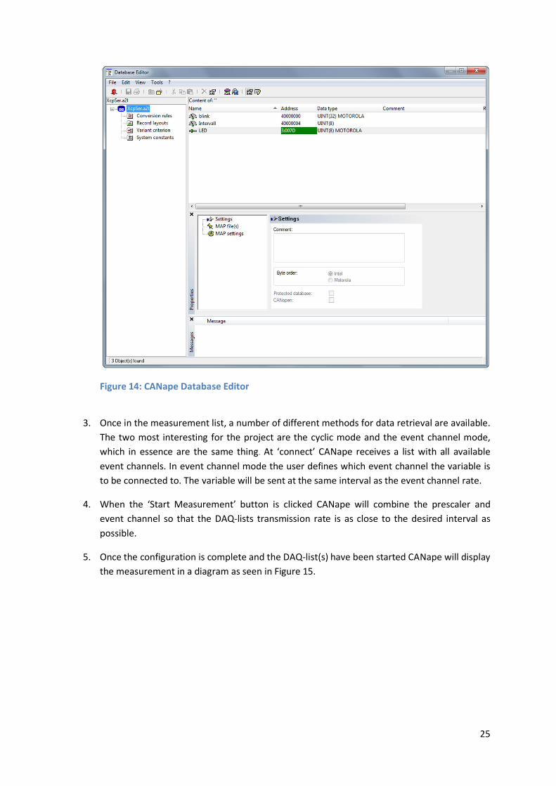
1. The first step is to add the addresses and properties of the variable to the database (see
Figure 14).
2. After the database has been updated with the new value the variable can be included in the
measurement list.
4 The name “GNU” is a recursive acronym for “GNU's Not Unix!”
5 Portable Operating System Interface for Unix
25
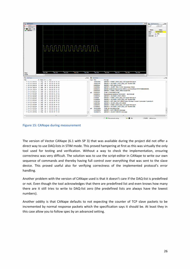
3. Once in the measurement list, a number of different methods for data retrieval are available.
The two most interesting for the project are the cyclic mode and the event channel mode,
which in essence are the same thing. At ‘connect’ CANape receives a list with all available
event channels. In event channel mode the user defines which event channel the variable is
to be connected to. The variable will be sent at the same interval as the event channel rate.
4. When the ‘Start Measurement’ button is clicked CANape will combine the prescaler and
event channel so that the DAQ-lists transmission rate is as close to the desired interval as
possible.
5. Once the configuration is complete and the DAQ-list(s) have been started CANape will display
the measurement in a diagram as seen in Figure 15.
Figure 14: CANape Database Editor
26
The version of Vector CANape (6.1 with SP 3) that was available during the project did not offer a
direct way to use DAQ-lists in STIM mode. This proved hampering at first as this was virtually the only
tool used for testing and verification. Without a way to check the implementation, ensuring
correctness was very difficult. The solution was to use the script-editor in CANape to write our own
sequence of commands and thereby having full control over everything that was sent to the slave
device. This proved useful also for verifying correctness of the implemented protocol’s error
handling.
Another problem with the version of CANape used is that it doesn’t care if the DAQ-list is predefined
or not. Even though the tool acknowledges that there are predefined list and even knows how many
there are it still tries to write to DAQ-list zero (the predefined lists are always have the lowest
numbers).
Another oddity is that CANape defaults to not expecting the counter of TCP slave packets to be
incremented by normal response packets which the specification says it should be. At least they in
this case allow you to follow spec by an advanced setting.
Figure 15: CANape during measurement

27
5.5 QR5567 The target hardware for the XCP implementation is the QR5567 platform (also known as the G3-
board or as ODEEP – Open Dependable Electrical and Electronics Platform). It is a rapid prototyping
platform designed by QRTECH for developing systems and application within the automotive domain.
The physical layout can be seen in Figure 16.
The following features are available:
128MHz 32-bit FreeScale MPC5567™ microcontroller
Four CAN 2.0B interfaces with TJA1050 transceivers
Two LIN 2.0 interfaces
Two FlexRay interfaces with TJA1080 transceivers
10/100mbit Ethernet interface
Four 3.0A High Side Driver Outputs (HDO)
Four 2.8A Low Side Driver Outputs (LDO)
Eight analog or digital inputs
Micro SD-Card Interface
5V External Output
Two H-Bridge Drivers
One Universal Serial Bus (USB) interface
Compact Layout (160 * 100 mm)
Figure 16: The QR5567 rapid prototyping platform.

28
QR5567 is also one of the reference boards for Arctic Core, which means that a significant amount of
testing has taken place in regards of running Arctic Core on QR5567. This should (in theory) result in
a higher level of dependability for the project.
In order to transfer programs from the development platform (usually a PC or similar) to the board
itself, a programming device is needed. A simple solution to this problem is to use a programmer that
connects to the board via the JTAG connector and downloads the specified files directly to the flash
memory area on the board. The one used for the project was a USB Multilink Interface from P&E
Microcomputer Systems. In addition to the basic flashing feature it also has the capability to verify
the memory. To have the ability to debug a PEEDI (Powerful Embedded Ethernet Debug Interface)
from Ronetix was used. By using Telnet and TFTP (Trivial File Transfer Protocol) it is possible to
program the device and also use debug.
5.6 Vector CANcaseXL In order to run CANape in so called online mode, an external device containing the certification key is
needed. In addition to this key, the CANcaseXL also contains two physical CAN channels with D-SUB
connector ports and a power synchronization port.
In order to make use of the CANcaseXL’s CAN channels a special cable had to be manufactured that
could connect the D-sub9 connectors with the connectors on the QR5567. This was done in the
laboratory at QRtech.
There were some issues with the CANcaseXL, the most severe was the fact that when connected it
seemed to cause Blue-Screen events at random. Although never confirmed that it was the cause, the
CANcaseXL was always connected to the computer if it had an occurrence of Blue-Screen, typically
one or two per day, regardless of whether it was being used or not.
29
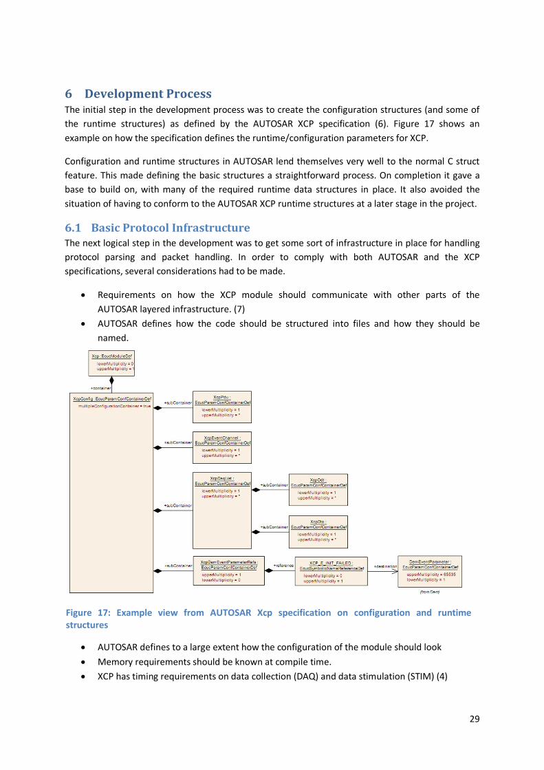
6 Development Process The initial step in the development process was to create the configuration structures (and some of
the runtime structures) as defined by the AUTOSAR XCP specification (6). Figure 17 shows an
example on how the specification defines the runtime/configuration parameters for XCP.
Configuration and runtime structures in AUTOSAR lend themselves very well to the normal C struct
feature. This made defining the basic structures a straightforward process. On completion it gave a
base to build on, with many of the required runtime data structures in place. It also avoided the
situation of having to conform to the AUTOSAR XCP runtime structures at a later stage in the project.
6.1 Basic Protocol Infrastructure The next logical step in the development was to get some sort of infrastructure in place for handling
protocol parsing and packet handling. In order to comply with both AUTOSAR and the XCP
specifications, several considerations had to be made.
Requirements on how the XCP module should communicate with other parts of the
AUTOSAR layered infrastructure. (7)
AUTOSAR defines how the code should be structured into files and how they should be
named.
AUTOSAR defines to a large extent how the configuration of the module should look
Memory requirements should be known at compile time.
XCP has timing requirements on data collection (DAQ) and data stimulation (STIM) (4)
Figure 17: Example view from AUTOSAR Xcp specification on configuration and runtime structures

30
6.2 Development of testing tools In order to develop and simultaneously test the implementation without the constant need to flash
the code onto the hardware, it was decided to create a standalone Windows XCP slave (XcpServer6)
using the same codebase library as would run on the actual hardware. Arctic Core itself was not
designed to be compiled on a non-embedded system, which ruled out using it as a host for the XCP
module.
It was however important that the interface to the core XCP code remained as close as possible to
that which would be required to run on the actual platform to reduce problems and bugs that might
be introduced due to differences in behaviour. This implied emulating the interfaces that the XCP
module would be using when communicating.
Since it had been previously determined that Arctic Core only had support for CAN communication,
this would be the initial choice of communication model. As it turns out, Vectors CANape toolkit
installs a virtual CAN bus, which can be used to communicate with CANape as if the real CANcaseXL
CAN bus is used, the API of which was available as a download from the authors of CANape.
The first instance of the XCP slave was using the above mentioned Virtual CAN bus and was working
as a starting point. However, due to some annoying behaviour of this bus, where a single error could
throw the whole virtual bus into an error state requiring a ‘disconnect’ of all CAN devices before it
would normalize, testing was tedious.
Given that XCP is also defined to run on TCP/IP for which CANape also has support, the development
platform was rewritten to function as a standard TCP/IP server, and the interface against the core
XCP module was changed to that which would have been used for TCP/IP communication with the
module inside Arctic Core had it supported this type of communication.
This change simplified XcpServer, since it was now using standard Posix7 socket API instead of a
proprietary API for the virtual CAN bus, it was able to run the XCP slave on one physical computer
and CANape on another as well as prepare the module for TCP/IP support when Arctic Core adds
support for TCP/IP as a communication model.
6 XCP slave based in windows for used in the development of XCP protocol
7 Portable Operating System Interface for Unix
31
7 Result The XCP module is developed in C, taking advantage of C99 features such as designated
initializers/inttypes.h and varadic macros. It is geared towards integration into an AUTOSAR
compatible system. However it has few actual requirements on the surrounding system, allowing the
module to be used in a non AUTOSAR context with only small adaptations.
7.1 AUTOSAR Integration of the XCP module The AUTOSAR XCP specification has defined entry points into the XCP module for the different
transport protocols. For the two of interest in this case (CAN and Ethernet) the following entry points
are defined where <module> is either “Eth” or “Can”
<module>_Transmit():
Implemented by the CanIf/SoAdIf AUTOSAR subsystems. This function is used to signal
transmission of data over the given transport protocol. It allows for two different modes. A
buffering model or a copy free model.
o With the buffering model, the transport subsystem copies the given data into
internal buffers and transmits at a later stage, at which point it calls a confirmation
function (Xcp_<module>TxConfirmation()) to signal the finished transmission of data.
o In the copy free model, only the size of the data requested to be transmitted is given
in the call to Transmit. When the transport layer subsystem is ready to transmit it
asks for a pointer to the actual data from the requesting subsystem
(Xcp_<module>TriggerTransmit())
Xcp_<module>RxIndication():
Implemented in the XCP module. This function is called by the CAN/Ethernet subsystems in
AUTOSAR when a data packet on a XCP assigned PDU is received. It contains the packet and
the packet length.
Xcp_<module>TxConfirmation():
Implemented in the XCP module. Called by AUTOSAR CAN/Ethernet… subsystems to confirm
that a data packet has been transmitted by the transport layer.
Xcp_<module>TriggerTransmit():
Implemented in the XCP module. Called by AUTOSAR CAN/Ethernet… subsystems when the
transport layer subsystem is about to send a data packet previously requested by a
<module>_Transmit() call by XCP. This allows a memory copy free transmit of data.
Only the buffered approach to transmission was implemented, partly due to its simplicity but mainly
due to lack of support in the Arctic Core AUTOSAR implementation for the copy free method.
The specification also states that the XCP module should implement a main function that should be
called on a fixed cyclic speed. It is said that “These functions are directly called by Basic Software
Scheduler.” (3) But there is no mention on how this is expected to be realized in the RTE or Basic

32
Scheduler. Thus currently the following functions need to be explicitly called by the integrator of the
AUTOSAR system.
Xcp_MainFunction():
Implemented in the XCP module and expected to be called by the Basic Software Scheduler.
Since this is currently not realized in the Arctic Core AUTOSAR implementation. The
Integrator is required to call this on a fixed cyclic speed to process received and sent XCP
messages.
Xcp_MainFunction_Channel(channel)
Implemented in the XCP module and is the entry point for triggering the specified XCP event
channel. This should be called by the AUTOSAR integrator at the rate configured for that
event channel and preferably at points in the software where the internal state is consistent.
7.2 Code Organization The AUTOSAR XCP specification also imposes restrictions on the namespace of global variables as
well as how the file/name and structure of your module should be defined. All global variables in an
AUTOSAR module must be named according to the standard “<module>(_)<name>” to avoid
namespace clashes between modules in the AUTOSAR layered architecture. The underscore has
apparently been deemed optional since it is often omitted in the specifications. Filename should
follow the same pattern of naming.
The AUTOSAR XCP specification defines the following files explicitly (see Figure 18 for the
correlations between the files):
Xcp.c – Main code for the XCP subsystem.
Xcp_Cfg.c/h – Compile time configuration parameters for the XCP module.
XcpOnEth.c – All code concerning XCP being transported over Ethernet.
XcpOnEth_Cbk.h – Extern function declarations for callbacks that other AUTOSAR components will call on reception of data over Ethernet.
XcpOnCan.c – All code concerning XCP being transported over CAN.
XcpOnCan_Cbk.h – Extern function declarations for callbacks that other AUTOSAR components will call on reception of data over CAN.
Xcp_ConfigTypes.h – Should contain all structures required in Xcp_Cfg.h/c to configure the XCP subsystem.
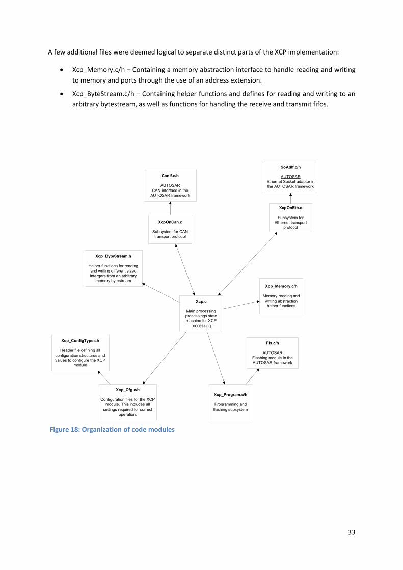
33
A few additional files were deemed logical to separate distinct parts of the XCP implementation:
Xcp_Memory.c/h – Containing a memory abstraction interface to handle reading and writing
to memory and ports through the use of an address extension.
Xcp_ByteStream.c/h – Containing helper functions and defines for reading and writing to an
arbitrary bytestream, as well as functions for handling the receive and transmit fifos.
Figure 18: Organization of code modules
Xcp.c
Main processing processings state machine for XCP
processing
Xcp_Program.c/h
Programming and flashing subsystem
XcpOnCan.c
Subsystem for CAN transport protocol
Xcp_Memory.c/h
Memory reading and writing abstraction helper functions
Xcp_ByteStream.h
Helper functions for reading and writing different sized intergers from an arbitrary
memory bytestream
XcpOnEth.c
Subsystem for Ethernet transport
protocol
Xcp_Cfg.c/h
Configuration files for the XCP module. This includes all
settings required for correct operation.
CanIf.c/h
AUTOSARCAN interface in the
AUTOSAR framework
SoAdIf.c/h
AUTOSAREthernet Socket adaptor in the AUTOSAR framework
Fls.c/h
AUTOSARFlashing module in the AUTOSAR framework
Xcp_ConfigTypes.h
Header file defining all configuration structures and values to configure the XCP
module

34
7.3 Memory Abstraction The XCP specification defines that any address used to reference an object/variable through the XCP
protocol should be combined with an address extension to fully identify the object. It is quite vague
in defining how the address extension should be used, but one example mentioned is to be able to
address multiple CPU’s address spaces even if they do not share physical memory.
To address this, a lightweight memory access abstraction was added to the module through which all
memory reading and writing is performed. This has the additional benefit that any internal or
external data of the ECU can be mapped into a flat address space and read and written as normal
memory. The use of the memory abstraction layer allowed the implementation of reading and
writing directly to AUTOSAR DIO8 Ports and Channels without any intermediary code written by the
user of the XCP module.
7.4 Demo Application During the development process a demonstrator application on the QR5567 was created. A standard
RC-Servo9 was attached to a PWM port of the QR5567 as well as to an analog port reading the
electrical current draw of the servo. This allowed monitoring of the current draw over XCP utilizing
DAQ lists, whilst controlling the servo using the online calibration feature of XCP.
The XCP demonstrator shows, in an understandable and simple way, the areas of application of XCP
itself. It could easily be extended to support optional features such as writing to non-volatile memory
for a more complete demonstration device when implemented in the core XCP module.
The usefulness of XCP was also made clear, and an actual need for calibration occurred, when the
initial RC-Servo used had to be replaced. The new servo required different pulse widths in order to
use its full range.
8 DIO: Digital Input Output
9 RC-Servo: Normal servo using in remote-controlled cars/planes/boats

35
8 Discussion
8.1 Implementation The behavior of the protocol is defined by the specification, there for no consideration regarding
functionality had to be made. The implementation had to conform. This can be an advantage; no
time needs to be spent on deciding how the implementation should work. The drawback is of course
that as a developer a lot of freedom is lost. As an example a sizeable amount of rework was done
when the dynamic allocation of DAQ-lists was added, due to the way in which AUTOSAR’s XCP
specification defined runtime structures. Initially, the specification was followed to the letter, which
at the time seemed like the logical choice. This however caused the implementation of dynamic DAQ
lists to become much more complicated than need be. It was eventually decided to modify the
runtime structures in a way more suited to dynamic memory allocation.
The refactoring of the configuration structures could have been avoided if the specification had been
clear that runtime structures where mainly a guide instead of a requirement which it was eventually
understood to be. If known in advance, less code would have been written to rely on a suboptimal
structure.
Making use of the functionality of the QR5567 proved slightly more labor intensive than was
assumed at first. The Arctic Core configuration template that maps the AUTOSAR ports to physical
pins only had support for the LED; the rest had to be added by hand. It should however be
emphasized that Arctic Core isn’t a QR5567 specific implementation and that no claim ever has been
made that states the availability of a complete configuration. Even so, the lack of a useable
configuration did require a lot of work that in essence was outside the scope of the project.
The Arctic Core AUTOSAR implementation had a nasty habit of crashing when too much debug
information was enabled and tasks where set to run often. It crashed in a mysterious way during
scheduling of tasks with no reference to what caused it. Since this was the default configuration, XCP
had to be limited to run processing at a very slow pace. 4 messages per second were about as fast as
it could run before triggering scheduling errors. Due to the lack of working debugging tools at the
start of the project, the reason was unknown during a large part of the initial phase of development.
This in turn caused the focus to shift to the development of virtual environment for a slave device
running on windows, rather than running on the targeted ECU.
8.2 The AUTOSAR initiative At a glance, AUTOSAR seems to be offering a lot of pros without any cons. This is of course not
entirely the case. First of all one must keep in mind that the AUTOSAR initiative is based on the desire
to make development of new E/E functionality less costly. Less effort has been put into making
software maintenance simpler. The assumption is that AUTOSAR will reduce the need for
maintenance and debugging because the platform itself will take care of most of the connections and
other sources of error. While this might be true, the fact that it is not obvious where the code is
executed does make it harder to find the source of the error. Whether this will be less time- and
money consuming than in the past remains to be seen, but at a glance it is uncertain. Introducing a
completely new architecture also means that knowledge of the old has little value.
36
Another drawback that is not mentioned in the AUTOSAR documentation is the increased complexity
for repairs and aftermarket services. Today, if there is a problem with an E/E component at the
brakes for example, the service technician can replace the appropriate ECU-box easily because all the
functionality is located in the same place. In an AUTOSAR compliant system there is no easy way to
know which box to replace or even if it is enough to replace just one. This means that auto
mechanics will have to master the art of computer software, becoming computer technicians as well.
A big incitement for creating large vehicle corporations has in the past been that a lot of the systems
and solutions can be reused in different car models all of which have essentially the same base
model. As an example the VW group owns many brands all producing similar standard cars; VW,
SEAT, Skoda and AUDI have a very similar range in small and medium sized segments. Instead of
developing a completely new model for each make a common platform is developed and the final
touch and finish is varied depending on which brand it is being produced as. As was stated in
previous chapters, the share of E/E in terms of new added value might be as much as 90% and that
the industry realizes that sharing the cost for the basic infrastructure would be a good idea. One
argument is that if the lion’s share of new development is in E/E and a lot of this will be done in a
more public fashion, the gain of having large corporations to reduce development costs might be a
thing of the past.
8.3 Future Work Programming
The ability to write to non-volatile memory was left out of the implementation. AUTOSAR and Arctic
Core have defined means of doing this, but currently reprogramming is left out of the XCP in
AUTOSAR specification. This does not necessarily hinder adding support for this in the Arctic Core
framework or for a specific device. It also seems likely that a future updated AUTOSAR XCP
specification might include XCP as a means for reprogramming devices.
Protocols
The big advantage with XCP over CCP is the possibility to run the same protocol over different
transport layers. As the project stands today the only available transport is CAN and to some extent
Ethernet. A logical continuation would be to implement the remaining transport layers. This depends
on how the development of Arctic Core progresses, if it is to be an AUTOSAR module it must use
interfaces that are yet to be included in Arctic Core.
Master
For some of QRtech’s customers the tools used in this project are considered to be too expensive.
They are very advanced with a lot of functionality which might not be used on a regular basis, at least
not in smaller application areas. A long term extension of the XCP project for QRtech could be to
create an XCP master application. The shape and form of such an implementation is of course open
to debate; but one option would be to base it on another tool that many customers already have e.g.
Matlab. This would allow for simple installation and reduced development time as a lot of the
framework would already be in place. It must however be emphasized that such a task, that of
writing an XCP master, is considerably larger than the original project i.e. the protocol
implementation.
37
9 References
1. AUTOSAR GbR. Technical Overview v. 2.2.2. AUTOSAR. [Online] 2008. [Citat: den 25 Oktober
2010.] http://www.autosar.org.
2. Renner, Christian. Chip vendors facing up to AUTOSAR challenge. EE Times Europe. [Online]
September 17, 2008. [Cited: February 22, 2011.] http://www.automotivedesign-
europe.com/en/chip_vendors_facing_up_to_autosar_challenge?cmp_id=7&news_id=210602111.
3. Vector Gmb. Downloads. Vector.com. [Online] den 1 December 2010. [Citat: den 7 December
2010.] http://www.vector.com.
4. Association for Standardization of Automation and Measuring Systems. XCP - "The Universal
Measurement and Calibration Protocol Family" - Version 1.0. 2003.
5. Andreas Patzer Vector Informatik. Optimising ECU parameters with XCP. Embedded Design India.
[Online] den 10 June 2009. [Citat: den 7 12 2010.] http://www.embeddeddesignindia.co.in.
6. AUTOSAR GbR. Specifications of Module XCP. AUTOSAR. [Online] R4.0 - 1.0.0, 2009. [Cited: 11 06,
2010.] http://www.autosar.org/download/R4.0/AUTOSAR_SWS_XCP.pdf.
7. —. Layered Software Architecture v. 3.0.0. AUTOSAR. [Online] den 30 November 2009. [Citat: den
15 November 2010.] http://www.autosar.org.
8. Heinecke, Harald, o.a., o.a. AUTomotive Open System ARchitecture - An Industry-Wide Initiative
to Manage the Complexity of Emerging Automotive E/E-Architechures. AUTOSAR. [Online] 2004.
[Citat: den 2 December 2010.] http://www.autosar.org.
9. Sedaghat, Alborz and Siby, Björn. Development of an AUTOSAR compliant prototyping platform.
Gothenburg : Chalmers University of Technology, 2009.

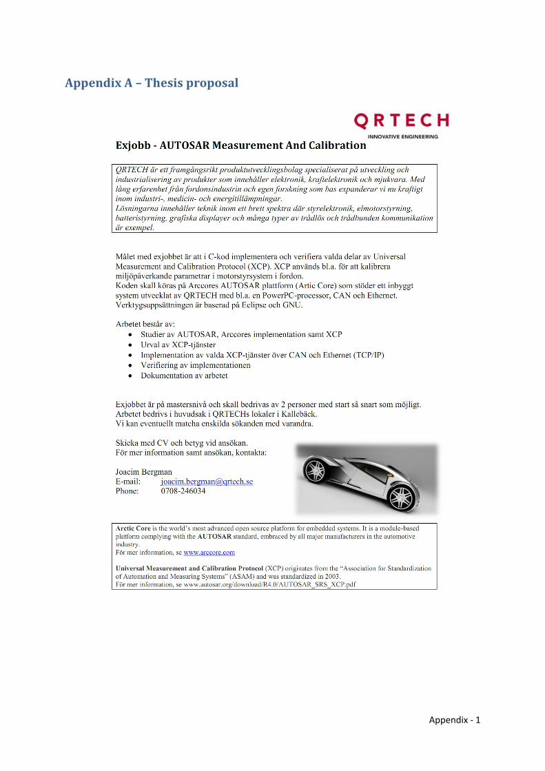
Appendix - 1
Appendix A – Thesis proposal

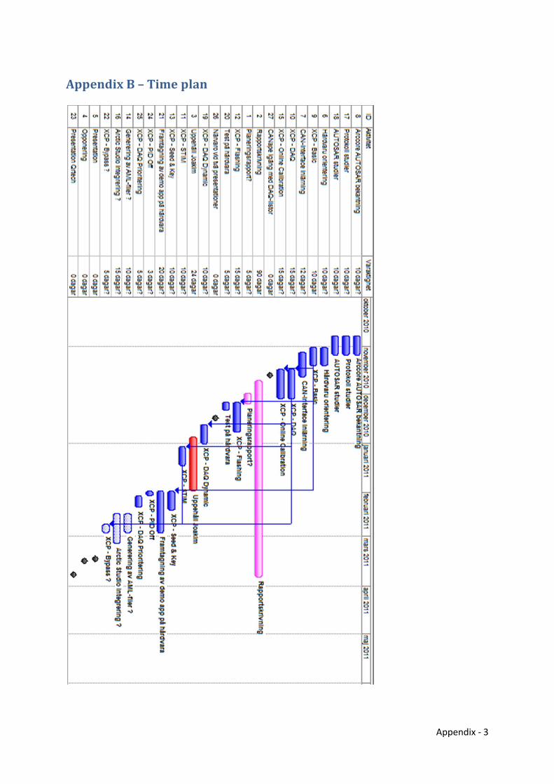
Appendix - 3
Appendix B – Time plan

Appendix - 5
Appendix C – Readme for XCP AUTOSAR module
***************** XCP - Calibration and Measurement Protocol ****************** XCP is a Calibration and Measurement protocol for use in embedded systems. It's a generalization of the previously existing CCP (CAN Calibration Protocol) This implementation is designed for integration in an AUTOSAR project. It follows AUTOSAR 4.0 XCP specification but support integration into an AUTOSAR 3.0 system. The requirements on the AUTOSAR infrastructure is limited, thus creating "emulation" functions to use the XCP module standalone is not a major hurdle for integration. Module support both static an dynamically configured DAQ lists, with dynamic DAQ lists the easier of the two to configure. It also support predefined DAQ lists when in dynamic mode in preparation for RESUME more support. There is support for reading and writing directly in memory on the device as well as a abstraction layer for memory to allow reading/writing directly to ports or user defined data. Module support multi threaded execution of data receive callbacks and main functions as long as a global mutex or interrupt disabling routine exists. It's only locked for very short periods of time during addition or removal of packets from queues. (the code should suite itself well for being replaced with a lockless alternative with atomic operations instead). Support Seed and Key protection for the different features of XCP. LIMITATIONS ------------- * Lack of page switching support for Online Calibration means it can be a bit error prone if large or multiple variables need to be modified while ECU is executing, since there is a risk it will sample the values while XCP is writing parts of them. * Currently in dynamic DAQ list configuration we malloc/free the number of DAQ's. This should probably be made into some internal pool of memory that can be configured at compile time. The requirements of how dynamic DAQ lists are allocated and released makes this internal HEAP reasonably simple to implement. * No support for RESUME mode, ECU Programming and PID off. * Interleaved mode is only partially tested since it is not allowed over the CAN protocol. * Only simple checksum support is implemented INTEGRATION ------------- To integrate XCP in a AUTOSAR project add the XCP code files to your project as a subdirectory. Make sure the subdirectory is in your C include path, as well as that all the .c files are compiled and linked to your project. There is no complete makefile included in the project. The application must call Xcp_MainFunction() at fast regular intervals to process incoming packets and send queued packets out onto the actual transport protocol. [This will be automatically taken care of when Arctic Core get XCP support built in] Arctic Core: Add the Xcp.mk file as an include directive to your projects makefile this should make use of Arctic Core build system to build XCP as a part
Appendix - 6
of your project. [Currently this will default to CAN interface] Standalone: Somewhat more complicated since it requires creation of a few headers to emulate AUTOSAR functionality, as well as hooking XCP up to a communication bus (Ethernet or CAN) XCP communicate with the actual protocol layer through two defined entry points Xcp_<protocol>RxIndication and <protocol>_Transmit, where <protocol> is either SoAdIf or CanIf depending on what underlying protocol is in use. For example for TCP/UDP the application needs to read first byte to get packet length and then pass this complete packet to XCP. For timestamp support the system also need to provide: StatusType GetCounterValue( CounterType, TickRefType ); You also need to provide implementation for a global mutex locking: void XcpStandaloneLock(); void XcpStandaloneUnlock(); CONFIGURATION --------------- All configuration of the module is done through the Xcp_Cfg.h and Xcp_Cfg.c file. These files could be automatically generated from AUTOSAR xml files or manually configured. Xcp_Cfg.h defines: XCP_PDU_ID_TX: The PDU id the Xcp submodule will use when transmitting data using CanIf or SoAd. XCP_PDU_ID_RX: The PDU id the XCP sub module will expect data on when it's callbacks are called from CanIf or SoAd. XCP_CAN_ID_RX: If GET_SLAVE_ID feature is wanted over CAN, XCP must know what CAN id it is receiving data on. XCP_PDU_ID_BROADCAST: If GET_SLAVE_ID feature is wanted over CAN, XCP must know what PDU id it will receive broadcasts on XCP_E_INIT_FAILED: Error code for a failed initialization. Should have been defined by DEM. XCP_COUNTER_ID: Counter id for the master clock XCP will use when sending DAQ lists this will be used as an argument to AUTOSAR GetCounterValue. XCP_TIMESTAMP_SIZE: Number of bytes used for transmitting timestamps (0;1;2;4). If clock has higher number of bytes, XCP will wrap timestamps as the max byte size is reached. Set to 0 to disable timestamp support XCP_IDENTIFICATION: Defines how ODT's are identified when DAQ lists are sent. Possible values are: XCP_IDENTIFICATION_ABSOLUTE: All ODT's in the slave have a unique number. XCP_IDENTIFICATION_RELATIVE_BYTE: XCP_IDENTIFICATION_RELATIVE_WORD: XCP_IDENTIFICATION_RELATIVE_WORD_ALIGNED: ODT's identification is relative to DAQ list id. Where the DAQ list is either byte or word sized. And possibly aligned to 16 byte borders. Since CAN has a limit of 8 bytes per packets, this will modify the limit on how much each ODT can contain.
Appendix - 7
XCP_MAX_RXTX_QUEUE: Number of data packets the protocol can queue up for processing. This should include send buffer as well as STIM packet buffers. This should at the minimum be set to 1 receive packet + 1 send packet + number of DTO objects that can be configured in STIM mode + allowed interleaved queue size. XCP_FEATURE_DAQSTIM_DYNAMIC: (STD_ON; STD_OFF) [Default: STD_OFF] Enables dynamic configuration of DAQ lists instead of statically defining the number of lists as well as their number of odts/entries at compile time. XCP_FEATURE_BLOCKMODE: (STD_ON; STD_OFF) [Default: STD_OFF] Enables XCP blockmode transfers which speed up Online Calibration transfers. XCP_FEATURE_PGM: (STD_ON; STD_OFF) [Default: STD_OFF] Enables the programming/flashing feature of XCP (NOT IMPLEMENTED) XCP_FEATURE_CALPAG: (STD_ON; STD_OFF) [Default: STD_OFF] Enabled page switching for Online Calibration (NOT IMPLEMENTED) XCP_FEATURE_DAQ: (STD_ON; STD_OFF) [Default: STD_OFF] Enabled use of DAQ lists. Requires setup of event channels and the calling of event channels from code: Xcp_MainFunction_Channel() XCP_FEATURE_STIM (STD_ON; STD_OFF) [Default: STD_OFF] Enabled use of STIM lists. Requires setup of event channels and the calling of event channels from code: Xcp_MainFunction_Channel() XCP_FEATURE_DIO (STD_ON; STD_OFF) [Default: STD_OFF] Enabled direct read/write support using Online Calibration to AUTOSAR DIO ports using memory extensions: 0x2: DIO port 0x3: DIO channel All ports are considered to be of sizeof(Dio_PortLevelType) bytes long. So port 5 is at memory address 5 * sizeof(Dio_PortLevelType) Channels are of BYTE length. XCP_FEATURE_GET_SLAVE_ID (STD_ON; STD_OFF) [Default: STD_OFF] Enable GET_SLAVE_ID support over the CAN protocol. Needs the following additional config: XCP_PDU_ID_BROADCAST XCP_CAN_ID_RX XCP_FEATURE_PROTECTION: Enables seed and key protection for certain features. Needs configured callback functions in XcpConfig for the seed calculation and key verification. XCP_MAX_DTO: [Default: CAN=8, IP=255] XCP_MAX_CTO: [Default: CAN=8, IP=255] Define the maximum size of a data/control packet. This will also directly affect memory consumptions for XCP since the code will always allocate XCP_MAX_DTO * XCP_MAX_RXTX_QUEUE bytes for data buffers. Xcp_Cfg.c: Should define a complete Xcp_ConfigType structure that then will be passed to Xcp_Init(). Example config with two event channels and dynamic DAQ lists follows below. The application should call Xcp_Mainfunction_Channel(0) once every 50 ms and Xcp_Mainfunction_Channel(1) once every second. ****************

Appendix - 8
#define COUNTOF(a) (sizeof(a)/sizeof(*(a))) static Xcp_DaqListType* g_channels_daqlist[2][253]; static Xcp_EventChannelType g_channels[2] = { { .XcpEventChannelNumber = 0 , .XcpEventChannelMaxDaqList = COUNTOF(g_channels_daqlist[0]) , .XcpEventChannelTriggeredDaqListRef = g_channels_daqlist[0] , .XcpEventChannelName = "Default 50MS" , .XcpEventChannelRate = 50 , .XcpEventChannelUnit = XCP_TIMESTAMP_UNIT_1MS , .XcpEventChannelProperties = 1 << 2 /* DAQ */ | 0 << 3 /* STIM */ }, { .XcpEventChannelNumber = 1 , .XcpEventChannelMaxDaqList = COUNTOF(g_channels_daqlist[1]) , .XcpEventChannelTriggeredDaqListRef = g_channels_daqlist[1] , .XcpEventChannelName = "Default 1S" , .XcpEventChannelRate = 1 , .XcpEventChannelUnit = XCP_TIMESTAMP_UNIT_1S , .XcpEventChannelProperties = 1 << 2 /* DAQ */ | 1 << 3 /* STIM */ } }; Xcp_ConfigType g_DefaultConfig = { .XcpEventChannel = g_channels , .XcpSegment = g_segments , .XcpInfo = { .XcpMC2File = "XcpSer" } , .XcpMaxEventChannel = COUNTOF(g_channels) , .XcpMaxSegment = COUNTOF(g_segments) }; **************** Seed & Key: To support Seed & Key you need to provide two functions to the config structure (XcpSeedFn and XcpUnlockFn) the seed function (XcpSeedFn) should populate the supplied buffer with a seed which will be transmitted to the master for it to calculate a key from. After the master have replied with the key, XcpUnlockFn will be called with the seed and key to verify access. If successfull the protected resource will be unlock during this session. Example for seed and key functions which just accept an identical reply of the seed: ***************** static uint8 GetSeed(Xcp_ProtectType res, uint8* seed) { strcpy((char*)seed, "HELLO"); return strlen((const char*)seed); } static Std_ReturnType Unlock(Xcp_ProtectType res, const uint8* seed, uint8 seed_len, const uint8* key, uint8 key_len) { if(seed_len != key_len) return E_NOT_OK; if(memcmp(seed, key, seed_len)) return E_NOT_OK; return E_OK; } ***************** CANAPE -------- Advanced settings: DAQ_COUNTER_HANDLING: Include command response Oddly CANAPE defaults to not expecting CTR value of tcp slave packets to be incremented by RES packets and the like which the specification

Appendix - 9
says they should be. At least they allow you to follow spec. DAQ_PRESCALER_SUPPORTED: Yes Implementation support prescaler