can be modelled using many different coding styles style …hoppe.eit.h-da.de/hdls/fsm.pdf · ·...
TRANSCRIPT

State Machine Descriptions
• Can be modelled using many different coding styles
• Style guidelines available for Moore or Mealy type machines
• Several encoding schemes for state variables used in FSM descriptions

State Machine DescriptionsIn this module, you will learn basic techniques for describing finite state machines (FSMs) in VHDL. This includes the differences between Mealy and Moore state machines and how to describe each type so that synthesis tools recognize the description as a finite machine.
After completing this module, you will be familiar with:
• The different types of circuits that you can build as FSMs, and their characteristics.
• How you can describe the controller/sequencer blocks of your design as FSM descriptions.
• The tasks associated with building controllers/sequencers using the VHDL language for synthesis.

Characteristics of State Machine Descriptions
• State register• Use enumerated data type• Clock specification• Specification of state transition• Specification of the outputs• Reset/set signal (optional)

Characteristics of State Machine Descriptions
Four basic requirements to describe a finite state machine.
• A state register that holds the current state of the machine.• A clock specification.• Specification of the state transitions.• Specification of the outputs.• Optional reset/set specification.
Synthesis tools allow a variety of styles for describing FSM’s
Three-process style: • A process for the state transition specification, • A process for the state register,• and a process for specifying the outputs.

State Register Requirements
(for Automatic State Machine Encoding)
• Clocked signal or variable• Enumerated type• State variable assumes the default type
value unless it is set to a start state

State Variable RequirementsTo ensure that synthesis tools can perform state machine analysis and use its state machine encoding algorithms, there are requirements regarding the state register in the description.The state register in the description must be defined as either a clocked signal or variable, and it must be an enumerated type. If it is not an enumerated type, this means you have already done the state encoding, in which case synthesis tools cannot perform any state machine analysis.You cannot assign a value to the state register outside the domain of the FSM.It is a good coding practice to explicitly set the state register to a start state.
State Encoding Options
You can choose a finite state machine (FSM) encoding technique and specify values for generics before reading your VHDL design into the synthesis tool.

State Encoding Options
Menu: Synthesize > VHDL OptionsCLI: add vhdl <options>
111110010011001000Gray
010001101000110111Random
100000
010000
001000
000100
000010
000001
OneHot
101100011010001000Binary (default)
sfsesdscsbsaEncoding
Example
FSM encoding example:

State Encoding OptionsThe FSM encoding techniques are:
• Binary -- Assigns the bit-level equivalents of sequential integers (0,1,2,3,…)to each state using the minimum pattern width possible. This encodingtechnique is the default.
• OneHot -- Assigns one bit to each state using a pattern that is as wide as the number of enumerated states.
• Random -- Assigns unique, arbitrary states using the minimum bit width.• Gray -- Assigns a sequence of Gray code patterns to the defined states.
(This minimizes the number of one-bit transitions.)
The FSM encoding technique that you choose applies to every process statement in the VHDL architecture.

State Encoding Options
To specify FSM encoding within your VHDL, declare an attribute for the state machine type. For example, declare the following type and attribute within the source file (or in a package):
attribute TYPE_ENCODING_STYLE : STRING;type STATES is (s0, s1, s2, s3);attribute TYPE_ENCODING_STYLE of STATES : type is “onehot”;
Where the syntax is: attribute TYPE_ENCODING_STYLE : STRING;type <enum_type_id> is (<state_ids>);attribute TYPE_ENCODING_STYLE of <enum_type_id> :
type is { “binary” “gray” “onehot” “random” };

Moore Machine
Moore Machine
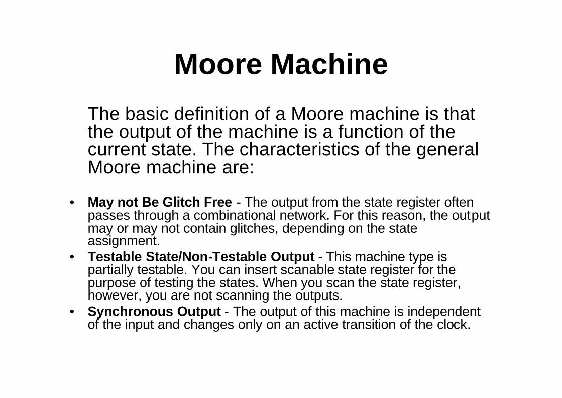
The basic definition of a Moore machine is that the output of the machine is a function of the current state. The characteristics of the general Moore machine are:
• May not Be Glitch Free - The output from the state register often passes through a combinational network. For this reason, the output may or may not contain glitches, depending on the state assignment.
• Testable State/Non-Testable Output - This machine type is partially testable. You can insert scanable state register for the purpose of testing the states. When you scan the state register,however, you are not scanning the outputs.
• Synchronous Output - The output of this machine is independent of the input and changes only on an active transition of the clock.

Moore MachineIn a circuit representing a general Moore machine, there are three recognizable blocks:
• The state transition logic for the state.• The flip-flops storing the current state of the machine.• The decode logic for the output.
The VHDL style used for describing a Moore-type machine builds upon this concept. In particular, the recommended style is to describe the state machine as three separate processes: (1) a clocked process for the state register, a combinational process for the state transition logic, and (3) a combinational process for the decode logic.

VHDL Moore Machine - Entity Description
ENTITY left_right_shifter ISPORT( a: IN std_ulogic;
clk: IN std_ulogic;sel: OUT std_ulogic_vector (3 DOWNTO 0));
END left_right_shifter;

VHDL Moore Machine Description
Although you can encapsulate an entire state machine in an entity by itself, it is not required. A state machine can be part of anarchitecture containing other parts of a design and a single architecture can contain multiple state machines.
The illustration on the facing page shows how you can relate thestate machine bubble diagram to the entity declaration that defines the ports for the state machine. In this example, signal a is the input that affects the state transitions and the signal sel is the name given to the 4-bit output shown in each state bubble. The Clock signal clkdoes not actually appear in the bubble diagram; it is assumed because a a state machine is a sequential design requiring a clock.
The viewfoils that follow show the three processes that make up the recommended style for a general Moore FSM description.

VHDL Moore Machine - State Register Description
ARCHITECTURE moore OF left_right_shifter ISTYPE states IS (s3,s2,s1,s0);SIGNAL present_state : states := s0;SIGNAL next_state : states := s0;BEGINsynch:PROCESS (clk)BEGINIF (clk = ‘1’ AND clk’LAST_VALUE = ‘0’) THENpresent_state <= next_state;
END IF;END PROCESS synch;END moore;

VHDL Moore Machine - State Register Description
The illustration on the facing page shows the state register portion of the general Moore left_right_shifter FSM description that meets the “recommended” style. This style for the state register portion of the description satisfies the requirement of defining a variable or signal that specifies the current state of the machine (present_state) and, in this case, the next state of the machine (next_state).
Notice that the type (states) of the signals in the code is not a key word; it can be any enumerated type that you define. Also, this code satisfies the requirement of a clocked process that defines the clock edge and makes the next-to-present state assignment.

VHDL Moore Machine - State Transition Description
state_transition:PROCESS(a, present_state)BEGINnext_state <= s0;CASE present_state ISWHEN s0 => CASE a IS
WHEN ‘0’ => next_state <= s3;WHEN OTHERS => next state <= s1;END CASE ;
WHEN s1 => CASE a ISWHEN ‘0’ => next_state <= s0;WHEN OTHERS => next state <= s2;END CASE ;
WHEN s2 => CASE a ISWHEN ‘0’ => next_state <= s1;WHEN OTHERS => next state <= s3;END CASE ;
WHEN s3 => CASE a ISWHEN ‘0’ => next_state <= s2;WHEN OTHERS => next state <= s0;END CASE ;
END CASE;END PROCESS state_transitions;

VHDL Moore Machine - State Transition Description
The illustration on the facing page shows the state transition logic portion of the general Moore left_right_shifter FSM decription. This code satisfies the requirement of defining the state transitions. As you can see, the style for the state transition logic uses a CASE statement. This is an entirely combinatorial process; the clock specification was defined in the state register portion of the description on page 4-16. Also, notice the process sensitivity list. The state transition logic is sensitive to signal a and the present state of the machine.
Assigning s0 to the next_state signal done to prevent the machine from entering an unknown state. For example, if you use one-hot encoding, the synthesized result will contain four flop-flops for the state register (due to the 4-bit output). With four flip-flops, there are 16 real hardware states; this design only uses four, which leaves 12 unknown states. For this reason, it is good practice to initially set the next_state signal to a known value.

VHDL Moore Machine - Output Decode Description
output_decode:PROCESS(present_state)BEGINCASE present_state ISWHEN s0 => sel <= “1000”;WHEN s1 => sel <= “0100”;WHEN s2 => sel <= “0010”;WHEN s3 => sel <= “0001”;END CASE;END PROCESS output_decode;

VHDL Moore Machine - Output Decode Description
The illustration on the facing page shows the output decode logic portion of the general Moore left_right_shifter FSM. This process, like the state decode logic process, is entirely combinatorial; the clock specification was defined in the state register portion of the description. Also, notice the process sensitivity list. The output is sensitive only to the present state of the machine, which is a deciding characteristic of a Moore machine. The output value is assigned to signal sel based on the present state of the machine.

Moore Machine with Output = State

Moore Machine with Output = State
The second type of machine to consider is also a Moore machine, but the state register is equal to the output. The output of the circuit is taken directly from the state register which is storing the present state, hence the term “output = state.”This circuit has three characteristics:
• Glitch Free - Because the output is taken directly from the state register and is not a function of the input, the output data is stable and is not subject to glitches.
• Testable - Because the output is taken directly from the state register, inserting scanable registers gives you the capability of testing the state and the output. This differs from the partially testable general Moore machine.
• Synchronous Output - Like the general Moore machine, the output of this machine is independent of the input and will change only with an active transition of the clock.

Moore Machine with Output = State
In a circuit representing an “output-equal-state” Moore machine, there are two recognizable blocks:
• The transition logic for the state.• The registers storing the current state of the machine.
This type of Moore machine requires the same number of flip-flops for the state register as outputs in the circuit. For example, if your circuit requires a 4-bit output, an “output-equal-state” Moore implementation requires four flip-flops. The same circuit described as a general Moore machine requires only as many flip-flops as necessary to store the state values (for example, for states require only two flip-flops). Hence an implementation trade-off exists.
Moore Machine with Glitch Free Output

Moore Machine with Glitch Free Output
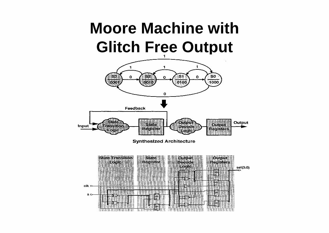
The third type of machine to consider is another variation of the general Moore machine. This machine also consists of output registers for a glitch-less output. The output registers comprise a second bank of flip-flops; the state register comprises the first bank. The output is latched on the opposite clock edge that latches the state. Therefore, the delay through the output decode logic must be at most the clock pulse width minus the setup time of the output latches.This circuit has three characteristics:
• Glitch Free - Because the output is taken directly from registers and is not a function of the input, the output data is stable and is not subject to glitches.
• Testable - Because the output is taken directly from registers, inserting scanableregisters gives you the capability of testing the state and the output. This differs from the partially testable general Moore machine.
• Synchronous Output - Like the general Moore machine, the output of this machine is independent of the input and will change only with an active transition of the clock.

Moore Machine with Glitch Free Output
In a circuit representing a glitch free Moore machine, there are four recognizable blocks:
• The transition logic for the state.• The registers storing the current state of the machine.• The decode logic for the output.• The output register bank.
This type of Moore machine requires a bank of flip-flops for the state register and a bank of output registers. For a machine with four states and a four-bit output, six total flip-flops are required. It is critical that the output decode logic settle to a valid value before the active clock edge reaches the output registers.

Mealy Machine

Mealy MachineThe other class of state machine to consider is the standard Mealy machine. The output of the Mealy machine is a function of the current state and the input. The characteristics of the Mealy machine are:
• Testable State/Non-Testable Output - Like the general Moore machine, this machine type is partially testable. You can insert scan registers for the purpose of testing the state; however, when you scan the state register in this type of machine, you are not scanning the outputs.
• Asynchronous Output - Because the output of the Mealy machine is a function of its input as well as its state, any change in input is reflected at the output. This allows asynchronous changes at theoutput of the machine. The asynchronous characteristic of the Mealy machine causes it to be prone to glitches as well as false outputs.

Mealy Machine
Like the general Moore machine, the Mealy machine consists of three recognizable blocks:
• The transition logic for the state.• The state register.• The decode logic for the output. In the Mealy machine,
the transition logic for the state and/or the input are also fed through to drive the output decode logic.

VHDL Mealy Machine - Entity Description
ENTITY left_right_shifter ISPORT( a: IN std_ulogic;
clk: IN std_ulogic;sel: OUT std_ulogic_vector (3 DOWNTO 0));
END left_right_shifter;
VHDL Mealy Machine - Entity Description
Like the general Moore machine just discussed, you can also relate the Mealy state machine bubble diagram to the entity declaration that defines the ports for the design. Although the Mealy machine behaves differently than the Moore machine, the entity declaration is the same. That is, the interface from the Mealy machine to the outside is the same as that of the Moore machine.
The following three examples show the template style for a Mealy FSM description. Like the general Moore machine, this basic template for the Mealy consists of a three-process description. One process each for the state transition logic, the state register, and the output decode logic.

VHDL Mealy Machine - State Register Description
ARCHITECTURE mealy OF left_right_shifter ISTYPE states IS (s3,s2,s1,s0);SIGNAL present_state : states := s0;SIGNAL next_state : states := s3;BEGINsynch:PROCESS (clk)BEGINIF (clk = ‘1’ AND clk’LAST_VALUE = ‘0’) THENpresent_state <= next_state;
END IF;END PROCESS synch;END mealy;

VHDL Mealy Machine - State Register Description
The basic template style for the Mealy machine state register process is identical to the Moore machine state register process shown on page 4-16. Again, you must define the present_state register as either a signal or variable (you can also optionally define the next_state register as in the example). The state register process is a clocked process that defines the clock edge and makes the next-to-present state assignment.

VHDL Mealy Machine - State Transition Description
state_transition:PROCESS(a, present_state)BEGINnext_state <= s0;CASE present_state ISWHEN s0 => CASE a IS
WHEN ‘0’ => next_state <= s3;WHEN OTHERS => next state <= s1;END CASE ;
WHEN s1 => CASE a ISWHEN ‘0’ => next_state <= s0;WHEN OTHERS => next state <= s2;END CASE ;
WHEN s2 => CASE a ISWHEN ‘0’ => next_state <= s1;WHEN OTHERS => next state <= s3;END CASE ;
WHEN s3 => CASE a ISWHEN ‘0’ => next_state <= s2;WHEN OTHERS => next state <= s0;END CASE ;
END CASE;END PROCESS state_transitions

VHDL Mealy Machine - State Register Description
The basic recommended style for the Mealy machine state transition logic process is identical to the Moore machine state transition logic process.

VHDL Mealy Machine - Output Decode Description
outputs:PROCESS(a, present_state)BEGINCASE present_state ISWHEN s0 => CASE a IS
WHEN ‘0’ => sel <= “0001”;WHEN OTHERS => sel <= “0100”;END CASE ;
WHEN s1 => CASE a ISWHEN ‘0’ => sel <= “1000”;WHEN OTHERS => sel <= “0010”;END CASE ;
WHEN s2 => CASE a ISWHEN ‘0’ => sel <= “0100”;WHEN OTHERS => sel <= “0001”;END CASE ;
WHEN s3 => CASE a ISWHEN ‘0’ => sel <= “0010”;WHEN OTHERS => sel <= “1000”;END CASE ;
END CASE;END PROCESS outputs;

Mealy Machine with Glitch Free Output

Mealy Machine with Glitch Free Output
The final type of machine to consider is a variation of the standard Mealy machine. This is a standard Mealy machine that feeds a bank of output registers to create a synchronous, glitch-free output. The output is latched on the opposite clock edge on which the state is latched.
This circuit has three characteristics:
• Glitch Free - Because the output is taken directly from flop-flops, the output data is stable and is not subject to glitches.
• Testable - Because the output is taken directly from flip-flops, inserting scanable flip-flops gives you the capability of testing the state and the output. This differs from the partially testable standard Mealy machine.
• Synchronous Output - Unlike the standard Mealy machine, the output of this machine will change only with an active transition of the clock.

Mealy Machine with Glitch Free Output
In a circuit representing a glitch free Mealy machine, there are four recognizable blocks:
• The transition logic for the state.• The flop-flops storing the current state of the machine.• The decode logic for the output.• The output register bank.
This type of Mealy machine requires a bank of flip-flops for the state register and a bank of output registers. For a machine with fourstates and a four-bit output, a total of six flip-flops are required.You must clearly understand the input signal behaviour to implement this type of machine. The output is a function of the state and the input and is latched on the clock edge opposite the state latching. It is critical that the output decode logic settle to a valid value before the active clock edge reaches the output registers.

Module Summary
• State Machines are Characterized by:– State Register - current_state/next_state– State Transition Specification– Output Specification– Clock Specification– Optional Reset/Set specification
• State Machine Descriptions:– Can be modeled using many different coding
styles– AutoLogic II supports several encoding schemes
for the state register• A Three-Process Style is Recommended