calix r3.1 user guide
DESCRIPTION
Calix R3.1 User GuideTRANSCRIPT
Calix E3-12C/E5-120/E5-121 R3.1 User Guide
July 2011
#220-00374, Rev. 13


Proprietary Information: Not for use or disclosure except by written agreement with Calix. © Calix. All Rights Reserved.
Contents
About This Guide.................................................................... 11
Syntax Conventions ................................................................................................ 12
Chapter 1: Getting Started .................................................... 13
Introducing the Calix E3-12C/E5-120/E5-121 ......................................................... 14
About the Configurator Web Interface ................................................................... 15
Connecting to the E3-12C/E5-120/E5-121 .............................................................. 17
Connecting a PC to the E3-12C/E5-120/E5-121 ............................................. 17 Logging In to the E3-12C/E5-120/E5-121 Web Interface ................................ 18
Configuring the Management Interface Ports ....................................................... 20
Configuring the In-Band Management Interface ............................................. 20 Configuring an Out-of-Band Management Interface ....................................... 22 Verify Connectivity .......................................................................................... 23 Static Routing ................................................................................................. 23
Performing Initial/Basic System Setup .................................................................. 26
Viewing System Information ........................................................................... 26 Configuring the Initial Setup ............................................................................ 30 Configuring the General Setup ....................................................................... 32
Chapter 2: System Administration ....................................... 35
Managing System Access Control ......................................................................... 36
Configuring SNMP Management ............................................................................ 37
Managing Remote Access Privileges .................................................................... 38
Managing System User Accounts .......................................................................... 39
Setting up User Authentication ....................................................................... 41

4
Proprietary Information: Not for use or disclosure except by written agreement with Calix. © Calix. All Rights Reserved.
Upgrading System Software ................................................................................... 43
Performing a System Software Upgrade ......................................................... 43 Downgrading the System Software ................................................................. 46
Performing Backup and Restore Operations ........................................................ 47
Backing Up the System Database .................................................................. 47 Restoring a Backup Database ........................................................................ 48
Chapter 3: Configuring the Ethernet Links ......................... 49
Configuring the Ethernet Port(s) ............................................................................ 50
Configuring RSTP .................................................................................................... 51
RSTP Status Tab ............................................................................................ 53
Link Aggregation (IEEE 802.3ad) ........................................................................... 56
Configuring Aggregation ................................................................................. 56 Viewing Link Aggregation Status .................................................................... 58
Setting Up the Switch .............................................................................................. 59
Setup Note: External Media Gateway for SIP VoIP Traffic (E3-12C and E5-121) 62
Chapter 4: Creating System Profiles ................................... 63
Creating Service Profiles ........................................................................................ 64
Creating IGMP Profiles ................................................................................... 64 xDSL Profiles .................................................................................................. 67 Creating IP QoS Profiles ................................................................................. 74 Creating xDSL Alarm Profiles ......................................................................... 77
Creating Traffic Management Profiles ................................................................... 80
Creating ACL Profiles ..................................................................................... 80 Applying ACL Profiles to a Set of xDSL Ports ................................................. 83 Viewing ACL Port Mapping ............................................................................. 86
Creating VoIP Service Profiles ............................................................................... 87
Creating SIP Profiles ....................................................................................... 87 Creating a SIP Numbering Plan ...................................................................... 89 Creating Call Service Profiles ......................................................................... 95 Configuring DSP Profiles ................................................................................ 99 Configuring H.248 Profiles ............................................................................ 101

5
Proprietary Information: Not for use or disclosure except by written agreement with Calix. © Calix. All Rights Reserved.
Chapter 5: Configuring Data Services ............................... 105
Data Services Overview: Supported Service Models ......................................... 106
Configuring VLAN-per-Service Data Model (N:1) ................................................ 107
Data Provisioning Checklist: VLAN-per-Service Model ................................. 107 Configuring the Service VLAN and Assigning Membership .......................... 108 Configuring xDSL Port Settings: VLAN-per-Service Data Model .................. 110
Configuring VLAN-per-Port Data Model (1:1) ...................................................... 113
Data Provisioning Checklist: VLAN-per-Port Data Model .............................. 113 Configuring the Service VLAN and Assigning Membership .......................... 115 Configuring xDSL Port Settings: VLAN-per-Port Model ................................ 116 Double-Tag (DT) ........................................................................................... 118
Configuring TLS (Business Services) ................................................................. 125
Data Provisioning Checklist: TLS Model ....................................................... 125 Configuring the Service VLAN and Assigning Membership .......................... 127 Configuring xDSL Port Settings: TLS Model ................................................. 128 Configuring TLS for a VDSL Port .................................................................. 130 Configuring a TLS PVC for an ADSL Port ..................................................... 131 Configuring a Static Multicast MAC Address ................................................ 133
Chapter 6: Configuring Video Services ............................. 137
Residential Gateway Support ............................................................................... 138
Provisioning Checklist: Residential Gateway Services ................................. 139 Creating a VLAN for Unicast Subscriber Traffic ............................................ 141 Creating a Multicast VLAN and Group .......................................................... 143 Configuring Double Tagging: Residential Gateway Services ........................ 145 Applying VC Parameters to xDSL Ports for Residential Gateway Service .... 149
xDSL Video and Data Support: Static VLAN Model ............................................ 151
Video Provisioning Checklist: xDSL, Static VLAN Model .............................. 151 Configuring the Service VLAN and Assigning VLAN Membership ................ 153 Configuring xDSL Port Settings .................................................................... 154
Video and Data Support: Multicast VLAN Model ................................................ 157
Video Provisioning Checklist: VDSL, Multicast VLAN Model ........................ 158 E3-12C/E5-120/E5-121 Configuration Guidelines and Process: VDSL with Tagged CPE ........................................................................... 159 E3-12C/E5-120/E5-121 Configuration Guidelines and Process: VDSL with Untagged CPE ....................................................................... 162 Creating a Multicast VLAN and Group .......................................................... 166 Creating a VLAN for Unicast Video Traffic .................................................... 168

6
Proprietary Information: Not for use or disclosure except by written agreement with Calix. © Calix. All Rights Reserved.
Create a VLAN for Unicast Data Traffic ........................................................ 171 Setting Up VLAN Translation Rules for Tagged CPE Traffic ........................ 172
IGMP Settings and Statistics ................................................................................ 175
Enabling IGMP Proxy .................................................................................... 175 IGMP Proxy Settings: Residential Gateway Services ................................... 175 IGMP Proxy Settings: Standard Video VLAN Models ................................... 177 IGMP Configuration Options ......................................................................... 178 Viewing IGMP Status .................................................................................... 180 Viewing Multicast Groups for IGMP Port Joins ............................................. 181 Viewing IGMP Port Counters ........................................................................ 182
Chapter 7: Configuring VoIP Services (E3-12C/E5-121 Only) 183
VoIP Services Checklist for E3-12C/E5-121 ......................................................... 184
Setting the VoIP Mode ........................................................................................... 185
Setting the VoIP Interface ..................................................................................... 186
Configuring the Service VLAN and Assigning Membership .............................. 187
Configuring SIP and TDM Gateway Subscriber Service .................................... 190
Port View Screen (SIP) ................................................................................. 192
Configuring H.248 Service .................................................................................... 194
Configuring the Media Gateway .................................................................... 194 Configuring H.248 Subscriber Service .......................................................... 195 VoIP Port View Screen (H.248) .................................................................... 196
General VoIP Information ...................................................................................... 199
General Screen ............................................................................................. 199 Active Call Screen......................................................................................... 203 VoIP Port Status ........................................................................................... 204
Using SIP Call Services......................................................................................... 207
Do Not Disturb .............................................................................................. 208 Call Waiting ................................................................................................... 208 Calling Line Identification Restriction ............................................................ 209 Call Transfer ................................................................................................. 209 Digit Setting Screen ...................................................................................... 211 Table Management and Table Edit Screens ................................................. 212 Registration Delay Screen ............................................................................ 212
Setting Up Distinctive Ringing ............................................................................. 213

7
Proprietary Information: Not for use or disclosure except by written agreement with Calix. © Calix. All Rights Reserved.
Chapter 8: Basic Features Reference ................................ 215
Configuring Bonding Groups ............................................................................... 216
DHCP Relay Options ............................................................................................. 218
Configuring Layer 2 DHCP Relay ................................................................. 219 Configuring Layer 3 DHCP Relay ................................................................. 221 Editing and Deleting DHCP Relay Settings ................................................... 224
Setting Up PPPoA to PPPoE Conversions .......................................................... 225
Viewing the PPPoE-to-PPPoA Status for a PVC .......................................... 228 Configuring the E3-12C/E5-120/E5-121 as an PPPoE Intermediate Agent .. 230
Customizing xDSL Port Settings .......................................................................... 232
Copying xDSL Port Settings ......................................................................... 232 Advanced xDSL Port Settings ....................................................................... 234 Configuring Signal-to-Noise Ratio Settings on a Per-Line Basis ................... 237 Applying VC Parameters to xDSL Ports ........................................................ 238 Editing, Deleting, and Copying VCs .............................................................. 240
DSCP Mapping ....................................................................................................... 242
DSCP Setup ................................................................................................. 242 DSCP Map .................................................................................................... 243
Chapter 9: Traffic Management Features .......................... 245
MAC Forced-Forwarding ....................................................................................... 248
Enabling MACFF........................................................................................... 249 Configuring MACFF Settings ........................................................................ 250 MACFF: Configuring a Static IP Address for a Subscriber Port .................... 254 MACFF: Creating a Trusted MAC for CFM Tests ......................................... 255
DHCP Snooping ..................................................................................................... 256
DHCP Snoop Status Tab .............................................................................. 258 DHCP Counter Tab ....................................................................................... 259
Downstream and Upstream Broadcast ................................................................ 261
Downstream Broadcast Screen .................................................................... 261 Upstream Broadcast Screen ......................................................................... 262
Downstream QoS ................................................................................................... 264
MTU Size................................................................................................................. 265
Packet Filter ........................................................................................................... 266
8
Proprietary Information: Not for use or disclosure except by written agreement with Calix. © Calix. All Rights Reserved.
Upstream Limit ...................................................................................................... 268
MAC Filter ............................................................................................................... 269
MAC Filter Screen......................................................................................... 269
OUI Filter ................................................................................................................ 270
OUI Filter Screen .......................................................................................... 270
N1MAC .................................................................................................................... 272
Viewing N1MAC Status ................................................................................. 273
2684 Routed Mode ................................................................................................. 274
2684 Routed Mode Example ........................................................................ 274 Routed PVC Tab ........................................................................................... 276 Routed Domain Tab ...................................................................................... 278 RPVC ARP Proxy Tab .................................................................................. 280 Routed Gateway Tab .................................................................................... 281
Chapter 10: VLAN Management Features ......................... 283
Static VLANs .......................................................................................................... 284
Viewing VLAN Statuses ................................................................................ 284 Editing and Deleting Static VLANs ................................................................ 286
Multicast VLANs .................................................................................................... 287
Viewing MVLAN Statuses ............................................................................. 287 Editing and Deleting MVLANs ....................................................................... 288 Editing and Deleting an MVLAN Group......................................................... 288
VLAN Translation .................................................................................................. 290
Creating VLAN Translation Rules ................................................................. 291
Protocol VLAN ....................................................................................................... 294
Protocol VLAN Screen .................................................................................. 294
Chapter 11: Security Features ............................................. 297
Denial of Service (DoS) Security Features .......................................................... 298
Port Authentication ............................................................................................... 299
RADIUS Tab ................................................................................................. 300 802.1x Tab .................................................................................................... 302
Port Security .......................................................................................................... 304
Port Security Screen ..................................................................................... 304

9
Proprietary Information: Not for use or disclosure except by written agreement with Calix. © Calix. All Rights Reserved.
Access Control ...................................................................................................... 306
Access Control Overview .............................................................................. 306 SNMP ........................................................................................................... 306 SNMP Traps ................................................................................................. 308 SNMP Screen ............................................................................................... 310 Service Access Control Screen .................................................................... 311 Remote Management Screen ....................................................................... 312
Chapter 12: Troubleshooting and Maintenance ................. 315
Working with Alarms ............................................................................................. 316
Alarm Event Setup Screen ............................................................................ 318 Viewing Alarms ............................................................................................. 320 Setting Up Alarms ......................................................................................... 321 Viewing the Alarm History ............................................................................. 324
Alarm Troubleshooting Information .................................................................... 326
alm_input, alm_input2, and alm_input3 (External Alarm Input) ..................... 326 anti_spoofing ................................................................................................ 326 down ............................................................................................................. 326 fan_err (Fan error) ........................................................................................ 327 hw_mon_fail (Hardware monitor diagnosis fails) .......................................... 327 hw_rtc_fail (RTC diagnosis test fails) ............................................................ 327 sysLogin_fail (Login fail) ............................................................................... 328 temp_err (Temperature error) ....................................................................... 328 voip_ac_power_fail (AC power fails) ............................................................. 328 voip_battery_fail (Chip battery fail indication) ............................................... 329 voip_call_threshold_violate (Call threshold violation).................................... 329 voip_clock_fail (Chip clock fail indication) ..................................................... 329 voip_dc_power_fail (DC power fails) ............................................................. 329 voip_ringer_fault (Ringer fault indication) ...................................................... 329 voip_temp_error (Temperature error) ........................................................... 330 vol_err (Voltage error) ................................................................................... 330
Troubleshooting Specific Conditions .................................................................. 331
SYS or PWR LED Does Not Turn On ........................................................... 331 ALM LED Is On ............................................................................................. 331 SFP LNK LEDs Do Not Turn On ................................................................... 332 100/1000 LEDs Do Not Turn On ................................................................... 333 100/1000 Ethernet Port Data Transmission .................................................. 333 DSL Data Transmission ................................................................................ 334 No Voice Service on a VDSL Connection ..................................................... 334 Video Tiling or Dropped Video Streams ........................................................ 335 Local Server .................................................................................................. 335 Data Rate ...................................................................................................... 336

10
Proprietary Information: Not for use or disclosure except by written agreement with Calix. © Calix. All Rights Reserved.
Configured Settings ...................................................................................... 337 Password ...................................................................................................... 337 SNMP ........................................................................................................... 337 System Lockout ............................................................................................ 338 Telnet ............................................................................................................ 338 Recovering the Firmware .............................................................................. 339
Rebooting an E3-12C/E5-120/E5-121 ................................................................... 341
Viewing and Configuring System Logs ............................................................... 342
SysLog Screen ............................................................................................. 344
Monitoring Performance Data .............................................................................. 345
Viewing Ethernet Port Statistics .................................................................... 345 Viewing xDSL Port Statistics ......................................................................... 347 RMON Statistics............................................................................................ 349 RMON History Screen .................................................................................. 351 RMON History Detail Screen ........................................................................ 353 xDSL Line Data ............................................................................................. 355
Performing Diagnostic Checks ............................................................................ 363
Ping ............................................................................................................... 363 SELT, DELT (LDM), and OAM F5 Loopbacks .............................................. 363 MLT Testing .................................................................................................. 366 Continuity Fault Management (CFM) ............................................................ 370
MAC Table .............................................................................................................. 385
MAC Table Screen........................................................................................ 386
ARP Table ............................................................................................................... 387
How ARP Works ........................................................................................... 387 ARP Table Screen ........................................................................................ 388
Maintenance Features ........................................................................................... 389
Rebooting the System ................................................................................... 389 Resetting the Defaults ................................................................................... 391
E3-12C/E5-120/E5-121 Default Settings ............................................................... 394

11
Proprietary Information: Not for use or disclosure except by written agreement with Calix. © Calix. All Rights Reserved.
About This Guide
This manual is a general guide for planning your networks for, and configuring the Calix E3-12C/E5-120/E5-121 IP Digital Subscriber Line Access Multiplexer (DSLAM). It describes the features and applications of the device, and will assist carrier engineers and network planners in effectively deploying the E3-12C/E5-120/E5-121 in their networks.
Intended audience
The primary audience for this guide includes network planners and engineers, and other personnel responsible for planning and engineering carrier networks. It also is a guide for personnel involved in configuring, administrating, and operating the E3-12C/E5-120/E5-121 system and third-party equipment. It assumes you have an understanding of standard telecom terminology and practices.
Related documentation
The Calix E5-Series documentation suite consists of:
Calix E3-12C/E5-100 Engineering and Planning Guide Calix E3-12C/E5-120/E5-121 User Guide Calix E3-12C/E5-120/E5-121 CLI Reference Calix E3-12C Installation Guide Calix E5-100 Installation Guide Calix ODC-100 Installation Guide Managing E3-12C/E5-100 Service Units with CMS Calix Management System (CMS) Guide

12
Proprietary Information: Not for use or disclosure except by written agreement with Calix. © Calix. All Rights Reserved.
Syntax Conventions “Enter” means for you to type one or more characters. “Select” means for you to use
one of the predefined choices. Command and arrow keys are enclosed in square brackets. [ENTER] means the Enter,
or carriage return key; [ESC] means the Escape key and [SPACE BAR] means the Space Bar.
Mouse action sequences are denoted using a “>”. For example, Click Advanced Applications > VLAN > Static VLAN Setting means first click the Advanced Applications, then the VLAN submenu, and then click Static VLAN Setting.
The E3-12C/E5-120/E5-121 may be referred to as the “unit”, the “device”, or the “system”.
Graphics icons key
Service Unit Type
TV and Set Top Box
Server
Computer
DSLAM
Gateway
Central Office / ISP
Home Router
Hub / Switch
Software naming conventions
The software version number uses the format X.Yy.Zz, where:
X = the (major) release number
Yy = minor release / added features / changes
Zz = patches / bug fixes

Proprietary Information: Not for use or disclosure except by written agreement with Calix. © Calix. All Rights Reserved.
Chapter 1
Getting Started
This section introduces the Calix E3-12C/E5-120/E5-121 platform and its web interface for system management. This section also provides instructions for initial system turn-up and how to configure the management interface ports.
Note: For instructions to install the E3-12C/E5-120/E5-121 hardware and connect physical network interfaces, see the Calix E-Series Installation Guides.
Topics Covered
This section covers the following topics:
Introducing the Calix E3-12C/E5-120/E5-121 About the E3-12C/E5-120/E5-121 web interface Connecting to the Calix E3-12C/E5-120/E5-121 Configuring the E3-12C/E5-120/E5-121 management interface ports Performing initial system turn-up

14
Proprietary Information: Not for use or disclosure except by written agreement with Calix. © Calix. All Rights Reserved.
Introducing the Calix E3-12C/E5-120/E5-121
The E3-12C/E5-120/E5-121 is an IP-based DSLAM (Internet Protocol Digital Subscriber Line Access Multiplexer) that connects VDSL2 and voice subscribers to the Internet. As a high-performance and compact platform, it delivers broadband Internet access and telephony service (over existing POTS telephone wiring) to multi-tenant units (MTUs), hospitals, hotels, schools, university campuses and ISPs. The E3-12C/E5-121 additionally supports VoIP SIP, TDM gateway to a Calix C7 network, and H.248 telephony services.
The E3-12C/E5-120/E5-121 platform allows for convenient management and support of VDSL2 technology. Up to 24 VDSL subscribers can simultaneously utilize a wide range of powerful broadband services.
For details on the system description, features, and supported topologies, see the Calix E3-12C/E5-100 Engineering and Planning Guide.

15
Proprietary Information: Not for use or disclosure except by written agreement with Calix. © Calix. All Rights Reserved.
About the Configurator Web Interface
The Calix E3-12C/E5-120/E5-121 provides an embedded graphical user interface that you can access in one of two ways:
From a standard web browser, log in to the Web interface on the E3-12C/E5-120/E5-121 directly.
After adding an E3-12C/E5-120/E5-121 in Calix Management System (CMS), At the node level on the Navigation Tree, click Configurator. For details on adding a node to CMS, refer to the Calix publication, Managing E3-12C/E5-100 Service Units from CMS.
The web browser format allows for management access via local or remote TCP/IP connections, enabling you to perform all system management and operational functions.
Note: The E3-12C/E5-120/E5-121 also supports an embedded command line interface (CLI) for system management. For CLI usage information, see the Calix E3-12C/E5-120/E5-121 CLI Reference.
Web interface security
Each Web interface screen has a high or low privilege level security setting:
High privilege: Available to administrators with high privilege access, high privilege screens include tasks such as creating administrator accounts, restarting the system, saving changes to the non-volatile memory, and restoring the factory defaults. Non-volatile memory refers to the E3-12C/E5-120/E5-121 storage that remains even if the E3-12C/E5-120/E5-121 power is turned off. Administrators with high privilege access can use all screens including the lower privilege screens.
Low privilege: Administrators with the low privilege access are restricted to read-only, low privilege screens.
User PC system requirements
For a list of system requirements, refer to the product software release notes, accessible online on the Calix Customer Resource Center.

16
Proprietary Information: Not for use or disclosure except by written agreement with Calix. © Calix. All Rights Reserved.
E3-12C/E5-120/E5-121 web interface design
The E3-12C/E5-120/E5-121 web interface is comprised of two main functional areas (frames), defined as follows:
1. Navigation Menu: Displays the physical and logical elements of the system. Click an object on the navigation tree to display its attributes in the main window (Work Area).
2. Work Area: Displays information and attributes about objects selected on the Navigation Menu. View and modify settings in the Work Area, which includes overhead tabs and sub-tabs for displaying more specific functions for the selected category.
E3-12C/E5-120/E5-121 web interface controls
The E3-12C/E5-120/E5-121 web interface's basic operational controls are performed as follows:
Click an object on the navigation menu to display its sub-menu items below. Click a sub-menu item. Click the overhead tabs and sub-tabs in the work area to display options for that
function. Click Apply button to save changes to E3-12C/E5-120/E5-121 volatile memory. (Recommended) On the navigation menu, use the Config Save option to save your
changes to non-volatile memory. Click Logout to end a session and log out of the web interface.
Reference topics
Logging In to the E3-12C/E5-120/E5-121 Web Interface (on page 18)

17
Proprietary Information: Not for use or disclosure except by written agreement with Calix. © Calix. All Rights Reserved.
Connecting to the E3-12C/E5-120/E5-121
This section describes how to connect to the E3-12C/E5-120/E5-121 for system management. The following tasks are covered:
Establishing a PC connection to the E3-12C/E5-120/E5-121 Configuring the PC to communicate with the E3-12C/E5-120/E5-121 Logging in to the E3-12C/E5-120/E5-121 web interface
Connecting a PC to the E3-12C/E5-120/E5-121
This topic describes how to connect your PC to the E3-12C/E5-120/E5-121 and configure the PC to communicate with the E3-12C/E5-120/E5-121. These tasks are required to access the E3-12C/E5-120/E5-121 web interface.
Connection options
Web interface access requires a TCP/IP link between your PC and the E3-12C/E5-120/E5-121. You can connect to the E3-12C/E5-120/E5-121 web interface from the following two TCP/IP-capable management ports:
Out-of-band management port In-band management port
Use the front Console port first: If you use a TCP/IP connection (such as the web browser interface or a Telnet session) to configure the E3-12C/E5-120/E5-121 management interface, the connection drops when you modify the IP address or management VLAN ID from the default, and you are forced to reconnect using the new settings. For this reason, Calix recommends initially connecting to the CLI via a local console connection.
Connecting a PC to the E3-12C/E5-120/E5-121 local Console management port
To access the CLI, connect your PC to the E3-12C/E5-120/E5-121 serial port to establish a local console management connection. Use a 4P4C (RJ-22) connector cable as follows:
Connect the 4P4C plug to the E3-12C/E5-120/E5-121 serial port (labeled CONSOLE). Connect the DB-9 end of the cable to the serial port on your PC (COM1, COM2).
Use a VT100 terminal emulation program to connect to the E3-12C/E5-120/E5-121 CLI. Serial port connections use the following settings:
Baud Rate - 9600 Bps
Parity - None
Data Bits - 8

18
Proprietary Information: Not for use or disclosure except by written agreement with Calix. © Calix. All Rights Reserved.
Stop Bits - 1
Flow Control - None
Connecting a PC to the E3-12C/E5-120/E5-121 front Ethernet MGMT port
To access the web interface, connect your PC to the E3-12C/E5-120/E5-121 Ethernet MGMT port to establish a local management connection. Use a standard Ethernet jumper cable (RJ-45 connectors on both ends) as follows:
Connect one cable end to the E3-12C/E5-120/E5-121 Ethernet management port, located on the front panel (labeled MGMT).
Connect the other cable end to the Ethernet port on your PC.
For detailed wiring instructions, see the Calix E5-100 Installation Guide.
Logging In to the E3-12C/E5-120/E5-121 Web Interface
Use the following instructions to log in to the web interface.
To log in to the Web interface
1. Verify that your PC is connected to the E3-12C/E5-120/E5-121. See Connecting a PC to the E3-12C/E5-120/E5-121 (on page 17) for details.
2. Start your Web browser, and enter the IP address of the E3-12C/E5-120/E5-121 (default: 192.168.0.1) in the Location or Address field and press Enter to open the Connect to (IP address) dialog box.
19
Proprietary Information: Not for use or disclosure except by written agreement with Calix. © Calix. All Rights Reserved.
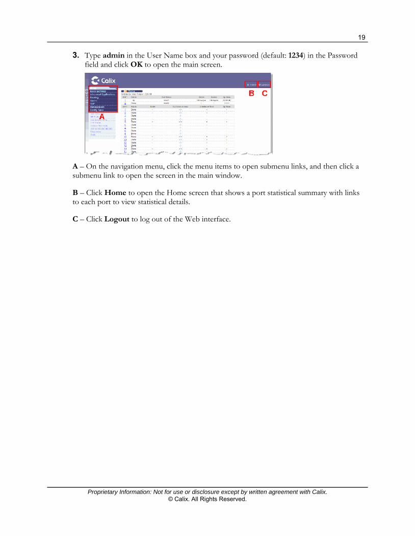
3. Type admin in the User Name box and your password (default: 1234) in the Password field and click OK to open the main screen.
A – On the navigation menu, click the menu items to open submenu links, and then click a submenu link to open the screen in the main window.
B – Click Home to open the Home screen that shows a port statistical summary with links to each port to view statistical details.
C – Click Logout to log out of the Web interface.

20
Proprietary Information: Not for use or disclosure except by written agreement with Calix. © Calix. All Rights Reserved.
Configuring the Management Interface Ports
To enable remote management of an E3-12C/E5-120/E5-121 service unit, you must configure it with a management VLAN and assign a unique IP address to it. Calix recommends performing this task from a local console connection to avoid losing connectivity to the unit when you change the IP address.
Once the management interface is established, you can connect to and manage the E3-12C/E5-120/E5-121 service unit remotely from CMS. You must have the following information on hand to turn up the E3-12C/E5-120/E5-121 node:
VLAN ID to use for device management IP address and subnet mask for device management IP address of the default gateway (that is, IP address of the upstream router interface)
Configuring the In-Band Management Interface
To configure the management interface, connect locally to the E3-12C/E5-120/E5-121 command-line interface (CLI). The E3-12C/E5-120/E5-121 ships with a 4P4C (RJ-22) console cable for local connections.
Note: If you use a TCP/IP connection (such as the web browser interface or a telnet session) to configure the E3-12C/E5-120/E5-121 management interface, the connection drops when you modify the IP address or management VLAN ID from the default, and you are forced to reconnect using the new settings. For this reason, Calix recommends initially connecting to the CLI via a local console connection.
To establish a local console connection to the CLI
1. Connect the console cable's 4P4C male connector to the E3-12C/E5-120/E5-121 Console port. Connect the other end of the cable to your PC serial port.
2. On your PC, establish a console session using a VT100 terminal emulation program (such as HyperTerminal or ProComm Plus). For example, launch a HyperTerminal session as follows:
a. On the Start > menu, click Programs > Accessories > Communications > HyperTerminal.
b. In the Connection Description dialog box, in the Name field, type a name for the session, then click OK. For example, type E5.
c. In the Connect To dialog box, in the Connect Using list, select the PC serial port to which the console cable is connected. For example, click COM1.

21
Proprietary Information: Not for use or disclosure except by written agreement with Calix. © Calix. All Rights Reserved.
d. In the COM# Properties dialog box, on the Port Settings tab, do the following:
In the Bits per Second list, click 9600.
In the Data Bits list, click 8.
In the Parity list, click None.
In the Stop Bits list, click 1.
In the Flow Control list, click None.
e. Click OK to connect.
3. In the console window, press the Enter key to initiate the console session.
4. Log into the E3-12C/E5-120/E5-121 CLI as follows:
a. At the Logon prompt, enter admin.
b. At the Password prompt, enter 1234.
Note: The logon ID and password are case sensitive.
The ras> command prompt displays upon successful login to the E3-12C/E5-120/E5-121 CLI.
Configure a management VLAN on the E3-12C/E5-120/E5-121 to match the management scheme (tag ID) used on your local LAN. Then assign a management IP address to the unit to enable remote management. The IP address must belong to the same IP subnet as the upstream router interface to enable traffic forwarding.
To configure the E3-12C/E5-120/E5-121 management interface
1. Set the E5 node host name. At the command prompt, enter: sys info hostname <name> (where <name> is the host name)
Example: sys info hostname E5
Note: After you set the host name, the basic CLI command prompt changes to [x]>, where [x] is the host name you supplied.
2. To use a VLAN other than VLAN 1 (default) for management, you must create a new VLAN and add the Ethernet ports to it. At the command prompt, enter: switch vlan set <vid> <portlist>:<F<T|U>> (where <vid> is the new VLAN ID, <portlist> is the port ID to add, and <F<T|U>> indicates a fixed port with the tag setting, where <T> = tagged and <U> = untagged)
Example: switch vlan set 66 enet1,enet2:FT
Note: You must add both of the Ethernet ports to the VLAN to enable remote management.

22
Proprietary Information: Not for use or disclosure except by written agreement with Calix. © Calix. All Rights Reserved.
3. Designate the new VLAN as the management VLAN. At the command prompt, enter: switch vlan mgmt set <vid> (where <vid> is the new management VLAN ID)
Example: switch vlan mgmt set 66
4. Assign a name to the VLAN to identify it as the management VLAN. At the command prompt, enter: switch vlan name <vid> <name> (where <vid> is the VLAN ID and <name> is the VLAN name)
Example: switch vlan name 66 Management
5. Assign a management IP address to the unit. At the command prompt, enter: ip set <ip>[</netmask>] (where <ip> is the IP address and </netmask> is the subnet mask)
Example: ip set 172.16.1.201/24
Note: The management IP address must belong to the same subnet as the upstream router interface, which serves as the default gateway.
6. Define the default gateway IP address. At the command prompt, enter: ip gateway <gateway ip> (where <gateway ip> is the IP address of the gateway router interface)
Example: ip gateway 172.16.1.1
7. Save the management interface configuration. At the command prompt, enter: config save
Note: The E3-12C/E5-120/E5-121 is now equipped to support remote management over a TCP/IP connection.
8. Type exit to log out of the CLI.
When finished, close the terminal session and disconnect the console cable from the E3-12C/E5-120/E5-121 unit.
Configuring an Out-of-Band Management Interface
The E3-12C/E5-120/E5-121 supports an out-of-band management interface that can be accessed locally via the MGMT port.
The out-of-band management interface is set on the IP Setup screen. For details, see Configuring the Initial Setup (on page 30). Unless you change it, the out-of-band management interface shipped from the factory is 192.168.0.1.

23
Proprietary Information: Not for use or disclosure except by written agreement with Calix. © Calix. All Rights Reserved.
Verify Connectivity
You can use the Diagnostics screen to ping the IP address of the default gateway, for example, to verify connectivity.
After configuring the management interface, use the following procedure to verify connectivity.
To verify platform connectivity
1. On the navigation menu, click Management > Diagnostics to open the Diagnostics screen.
2. In the IP Address box to the right of IP Ping, type the IP address for the device you are pinging.
Note: To ping the default gateway, use the command: ip ping <ip address>.
3. Optionally set the number of ping attempts, and then click Ping to view the results.
Static Routing
Use static routes to control how the E3-12C/E5-120/E5-121 forwards IP traffic when you configure the TCP/IP parameters manually. This can be useful when managing the E3-12C/E5-120/E5-121 remotely from a device with an IP address on a different subnet than the service unit's IP address.
To open the Static Routing screen
On the navigation menu, click Routing > Static Routing.

24
Proprietary Information: Not for use or disclosure except by written agreement with Calix. © Calix. All Rights Reserved.
The following table describes the elements of the Static Routing screen:
Element Description
Use the upper section of the screen to create a new static route.
Name Type a name to identify this static route (up to 31 characters; spaces and tabs are not allowed).
Destination IP Address
The IP network address of the final destination. Routing is always based on network number. If you need to specify a route to a single host, use a subnet mask of 255.255.255.255 in the subnet mask field to force the network number to be identical to the host ID.
IP Subnet Mask Enter the subnet mask for this destination.
Gateway IP Address Enter the IP address of the gateway. The gateway is an immediate neighbor of your device that forwards the packet to the destination. The gateway must be a router on the same segment as your device.
Metric The “cost” of transmission for routing purposes. IP routing uses hop count as the measurement of cost, with a minimum of 1 for directly connected networks.
Enter a number that approximates the cost for this link. The number need not be precise, but it must be between 1 and 15. In practice, 2 or 3 is usually a good number.
Add Click Add to save the settings to volatile memory.
Calix recommends periodically saving configuration changes to non-volatile memory using the Config Save option on the navigation menu.
The saved settings display in the summary table at the bottom of the screen.
Cancel Click Cancel to reset the fields to your previous configuration.
Use the lower section of the screen to view a summary of all static routes in the E3-12C/E5-120/E5-121.
Previous Page Click Previous Page to display the preceding page of static route entries.
Next Page Click Next Page to display the following page of static route entries.
Index The index number of the route.
Name The name of this static route.

25
Proprietary Information: Not for use or disclosure except by written agreement with Calix. © Calix. All Rights Reserved.
Element Description
Interface The name of an interface used by the static route. Ethernet indicates an inband Ethernet port. A value of enif indicates an out-of-band management port. VoIP means a VoIP interface (E3-12C/E5-121 only).
Destination Address The IP network address of the final destination.
Subnet Mask The subnet mask for this destination.
Gateway Address The IP address of the gateway. The gateway is an immediate neighbor of your device that forwards the packet to the destination.
Metric The cost of transmission for routing purposes.
Delete Select the rule(s) to remove in the Delete column, and then click the Delete button.
Cancel Click Cancel to clear the selected check boxes in the Delete column.

26
Proprietary Information: Not for use or disclosure except by written agreement with Calix. © Calix. All Rights Reserved.
Performing Initial/Basic System Setup
This section describes how to perform an initial turn-up and general setup of an E3-12C/E5-120/E5-121 system, using the Web interface.
The initial configuration includes IP and port setup. The General Setup includes configuring general device identification information and
system time that displays in the logs.
Viewing System Information
The System Information screen shows general device information and hardware polling information. You can check the firmware version number and monitor the hardware status in this screen.
To view system information
1. On the navigation menu, click Basic Settings > System Information to open the System Info screen.
2. View the following system information items:
System Name The device model name.
Product Part Number shows part number assigned to the device at the factory.
HW Revision Number The hardware revision of the device.
CLEI Code The CLEI code assigned to the device at the factory.
Software F/W Version The version number of the device’s current firmware including the date created.
DSP Code Version The Digital Signal Processor firmware version number. This is the modem code firmware.
Hardware Version The version of the physical device hardware. This field may be blank.
Serial Number The individual identification number assigned to the device at the factory. This field may be blank.
Ethernet Address The Ethernet Media Access Control (MAC) address of the device.
VoIP DSP Version (<e_type2 only) The VoIP Digital Signal Processor firmware version number.
Codec F/W Version The Codec firmware version.

27
Proprietary Information: Not for use or disclosure except by written agreement with Calix. © Calix. All Rights Reserved.
3. View the items the Hardware Monitor section of the screen. For descriptions of the parameters, refer the table below.
Select the Enable check box to turn on hardware monitoring. Clear the check box to disable it.
At the bottom of the screen, the Poll Interval(s) box displays how often (in seconds) this screen refreshes. To change the refresh interval, type a new number in the box and then click Set Interval. To stop statistic polling, click Stop.
4. If the E3-12C/E5-120/E5-121 has the external alarm interfaces wired out to any inputs, customize the names of the input sources so that equipment generating an alarm can be identified:
a. In the Name field, type a title for each external alarm (up to 31 characters).
b. Set the Triggered Mode to indicate whether the external alarm is triggered by a closed or open condition.
c. Click Apply to save your settings.
Hardware Monitor Element
Description
Temperature Unit Select C to display all temperature measurements in degrees Celsius. Select F to display all temperature measurements in degrees Fahrenheit.
Temperature-C Each temperature sensor can detect and report the temperature. Temperature sensor 1 is near the xDSL chipset. Temperature sensor 2 is near the central processing unit. Temperature sensor 3 is at the hardware monitor chip.
Current The current temperature at this sensor.
MAX The maximum temperature measured at this sensor.
MIN The minimum temperature measured at this sensor.
Average The average temperature measured at this sensor.
Threshold (Low) The lowest temperature limit at this sensor.
Threshold (Hi) The highest temperature limit at this sensor.
Status Displays Normal for temperatures below the threshold and Over for those above.
Voltage The power supply for each voltage has a sensor that can detect and report the voltage.
Current The current voltage reading.
MAX The maximum voltage measured at this point.
MIN The minimum voltage measured at this point.

28
Proprietary Information: Not for use or disclosure except by written agreement with Calix. © Calix. All Rights Reserved.
Hardware Monitor Element
Description
Average The average voltage measured at this sensor.
Threshold (Low) The lowest voltage limit at this sensor.
Threshold (Hi) The highest voltage limit at this sensor.
Status Normal indicates that the voltage is currently operating within an acceptable operating range; otherwise Abnormal is displayed.
Fan Speed (RPM) (E5-100 units only)
A properly functioning fan is an essential component (along with a sufficiently ventilated, cool operating environment) for the device to stay within the temperature threshold. Each fan has a sensor that can detect and report the fan’s Revolutions Per Minute (RPM).
Current The current RPM reading.
MAX The maximum RPM measured at this point.
MIN The minimum RPM measured at this point.
Average The average RPM measured at this sensor.
Threshold (Low) The lowest RPM limit at this sensor.
Threshold (Hi) The highest RPM limit at this sensor.
Status Normal indicates that the RPM is currently within an acceptable operating range; otherwise Abnormal is displayed.
External Alarm
Status
Name
Triggered Mode
The E3-12C/E5-120/E5-121 is able to detect up to three external alarm inputs for equipment connected to the ALARM connectors.
The Status column displays Normal when no alarm input has been detected or Abnormal when an alarm input has been detected.
To define a customized name for the external alarm inputs, type in a new name and click Apply.
Triggered Mode setting enables you to change the DB9 polarity for each external alarm input: close-alarm indicates that alarm input contacts are normally closed; open-alarm indicates that alarm input contacts are normally open. (The factory default is close-alarm.)
To change the Triggered Mode, select an option in the list, and then click Apply.

29
Proprietary Information: Not for use or disclosure except by written agreement with Calix. © Calix. All Rights Reserved.
Hardware Monitor Element
Description
External Relay / Status
The E3-12C/E5-120/E5-121 is able to send alarm output to another piece of equipment connected to the ALARM connector.
The Status column displays Normal when the E3-12C/E5-120/E5-121 is not sending alarm output to another piece of equipment. It displays Abnormal when the E3-12C/E5-120/E5-121 is sending alarm output to another piece of equipment.
Fan Trap Mode (E5-100 units only)
Select normal to have the E3-12C/E5-120/E5-121 send an SNMP trap when one fan's RPM is over the threshold, or two to have the E3-12C/E5-120/E5-121 send an SNMP trap when both fans' RPM is over the threshold. If you change the setting click Apply to save it.
Use this section of the screen to configure the hardware monitor threshold settings.
New Threshold / Apply
Configure new threshold settings in the fields below and click Apply to use them.
Index A sequential value.
Temperature-C (Hi) Configure the highest temperature limit at each sensor.
Note: If the average temperature of the device crosses this threshold, all xDSL traffic shuts down until the upper threshold is elevated above the average, or the average temperature returns back to the configured range.
Temperature-C (Lo) Configure the lowest temperature limit at each sensor.
Volt. (Hi) Configure the highest voltage limit at each sensor.
Volt. (Lo) Configure the lowest voltage limit at each sensor.
Fan (Hi) Configure the highest RPM limit at each sensor.
Fan (Lo) Configure the lowest RPM limit at each sensor.

30
Proprietary Information: Not for use or disclosure except by written agreement with Calix. © Calix. All Rights Reserved.
Configuring the Initial Setup
This section uses the Web interface for initial configuration. In the IP Setup screen, you configure the following:
Ethernet settings (IP address, IP mask, management VLAN ID and priority) for E3-12C/E5-120/E5-121 management through in-band ports.
Outband settings (IP address and IP mask) for E3-12C/E5-120/E5-121 management using the MGMT port.
VoIP IP settings (E3-12C/E5-121 only)
See also
For information about CLI commands, see the Calix E3-12C/E5-120/E5-121 CLI Reference.
E3-12C/E5-120/E5-121 Default Settings (on page 394).
The following illustration is taken from the E3-12C/E5-121 and includes VoIP setup fields.

31
Proprietary Information: Not for use or disclosure except by written agreement with Calix. © Calix. All Rights Reserved.
To set the initial configuration
1. Log in to the Web interface. See Logging In to the Web Interface (on page 18) for instructions.
2. On the navigation menu, click Basic Settings > IP Setup to open the IP Setup screen.
Note: Clicking Cancel before clicking one of the Apply buttons resets the fields to the currently-saved settings.
3. Enter the appropriate Ethernet and Outband IP settings, and then click Apply IP setting.
Note: If you change the IP address of the E3-12C/E5-120/E5-121, saving the configuration, you must use the new IP address to log in to the Web interface.
4. Enter the IP address of the default Management Gateway in dotted decimal notation, and then click Apply Gateway setting.
5. (E3-12C/E5-121 only) For instructions on setting up the VoIP settings, see Setting the VoIP Interface (on page 186).
6. On the navigation menu, use the Config Save option to save changes to non-volatile memory.
7. Click Save. The following screen opens. Click OK.
You can now use the device (with the other settings set to the defaults) to provision service.
Related topics
Logging In to the E3-12C/E5-120/E5-121 Web Interface (on page 18) Setting the VoIP Interface (on page 186) E3-12C/E5-120/E5-121 Default Settings (on page 394)

32
Proprietary Information: Not for use or disclosure except by written agreement with Calix. © Calix. All Rights Reserved.
Configuring the General Setup
This topic describes how to configure general device identification information and set the system time manually or get the current time and date from an external server when you turn on your device. The real time then displays in the logs.
To configure the general setup
1. On the navigation menu, click Basic Settings > General Setup to open the General Setup screen.
2. In the General Setup page, do the following:
a. In the Host Name box, type a descriptive name for identification purposes (up to 31 characters; spaces are not allowed).
b. In the Location box, type the geographic location of your device (up to 31 characters; spaces are not allowed).
c. In the Contact Person's Name box, type the name of the person in charge of this device (up to 31 characters; spaces are not allowed).
d. In the Stdio Timeout box, set the session timeout for the Console, TELNET, and WEBGUI (0 to 300 seconds). The default is 300 seconds. Enter 0 to disable the session timeout.
e. In the Use Time Server When Bootup box, select the time service protocol that the timeserver uses.
Not all time servers support all protocols, so you may have to use trial and error to find a protocol that works. The main differences between them are the time format.
Daytime (RFC 867) format displays the day, month, year and time with no time zone adjustment. When you use this format, Calix recommends that you use a Daytime timeserver within your geographical time zone.
Time (RFC-868) format displays a 4-byte integer giving the total number of seconds since 1970/1/1 at 0:0:0.
NTP (RFC-1305) is similar to Time (RFC-868).
None is the default value. Enter the time manually. Each time you turn on the device, the time and date will be reset to 2000-1-1 0:0.
f. In the Time Server IP Address box, type the IP address of your timeserver. The device searches for the timeserver for up to 60 seconds.
g. For the Current Time box, refresh the menu to update the displayed value from the time you opened this screen.
h. For the New Time box, type the new time in hour, minute and second format. Click Apply to view the new time in the Current Time field.

33
Proprietary Information: Not for use or disclosure except by written agreement with Calix. © Calix. All Rights Reserved.
i. For the New Date box, type the new date in year, month and day format. Click Apply to view the new date in the Current Time field.
j. In the Time Zone box, select the time difference between UTC (Universal Time Coordinated, formerly known as GMT, Greenwich Mean Time) and your time zone from the list box.
3. Click Add or Apply to save your changes to the system volatile memory.
4. (Recommended) On the navigation menu, use the Config Save option to save changes to non-volatile memory.

34
Proprietary Information: Not for use or disclosure except by written agreement with Calix. © Calix. All Rights Reserved.

Proprietary Information: Not for use or disclosure except by written agreement with Calix. © Calix. All Rights Reserved.
Chapter 2
System Administration
This section describes how to manage user access and perform administrative tasks on the database and software.
Topics Covered
This section covers the following topics and tasks:
Managing system access control Configuring SNMP management Managing remote access privileges Managing system user accounts Upgrading system software Performing backup and restore operations

36
Proprietary Information: Not for use or disclosure except by written agreement with Calix. © Calix. All Rights Reserved.
Managing System Access Control
This topic describes how to activate the service type and configure the service port numbers to access the system control.
Typically, the System Access Control settings are not changed.
To manage system access control
1. On the navigation menu, click Advanced Applications > Access Control > Service Access Control.
2. In the Service Access Control page, do the following:
a. For the Active check boxes, select the boxes for the corresponding services to enable access to the E3-12C/E5-120/E5-121.
b. For the Service Ports, enter a value to change the default service port for the Telnet, FTP, or Web services.
3. Click Add or Apply to save your changes to the system volatile memory.
4. (Recommended) On the navigation menu, use the Config Save option to save changes to non-volatile memory.

37
Proprietary Information: Not for use or disclosure except by written agreement with Calix. © Calix. All Rights Reserved.
Configuring SNMP Management
This topic describes how to configure SNMP access, community strings, SNMP traps, and a trusted host computer. SNMP community strings authenticate access and function as embedded passwords.
Note: If the network is configured with CMS, the CMS server listens on a SNMP trap for any E3-12C/E5-120/E5-121 autonomous messages including alarms, events, security events, threshold events, and dbchange events.
For detailed information on SNMP, see the Calix E3-12C/E5-100 Engineering and Planning Guide.
To open the SNMP screen
1. On the navigation menu, click Advanced Applications > Access Control > SNMP.
2. In the SNMP page, do the following:
a. In the Get Community box, type the get community, which is the password for the incoming Get- and GetNext- requests from the management station.
b. In the Set Community box, type the set community, which is the password for incoming Set- requests from the management station.
c. In the Trap Community box, type the trap community, which is the password sent with each trap to the SNMP manager.
d. In the Trap Destination 1-4 boxes, enter the IP address of a station where your SNMP traps are sent.
e. In the Port boxes, enter the port number where the station listens for SNMP traps.
f. In the Trusted Host box, type the IP address of a computer that is allowed to use SNMP to access the E3-12C/E5-120/E5-121.
A setting of 0.0.0.0 allows any computer to use SNMP to access the E3-12C/E5-120/E5-121.
3. Click Add or Apply to save your changes to the system volatile memory.
4. (Recommended) On the navigation menu, use the Config Save option to save changes to non-volatile memory.
Note: Typically, the SNMP Management settings are not changed.

38
Proprietary Information: Not for use or disclosure except by written agreement with Calix. © Calix. All Rights Reserved.
Managing Remote Access Privileges
This topic describes how to configure the IP address ranges of trusted computers that manage the E3-12C/E5-120/E5-121.
To manage remote management access
1. On the navigation menu, click Advanced Applications > Access Control > Secured Client.
2. In the Remote Management page, do the following:
a. Select the Enable check boxes to activate the secured client set that corresponds to the Index number.
The client set index number designates a group of one or more “trusted computers” from which an administrator can use a service to manage the E3-12C/E5-120/E5-121.
b. In the Start IP Address and End IP Address boxes, configure the IP address range of trusted computers that can manage the E3-12C/E5-120/E5-121.
The E3-12C/E5-120/E5-121 checks if the client IP address of a computer requesting a service or protocol matches the range set here. The E3-12C/E5-120/E5-121 immediately disconnects the session if it does not match.
c. For the Telnet, FTP, Web, ICMP, and SNMP check boxes, select services that may be used for managing the E3-12C/E5-120/E5-121 from the specified trusted computers.
3. Click Add or Apply to save your changes to the system volatile memory.
4. (Recommended) On the navigation menu, use the Config Save option to save changes to non-volatile memory.
Note: Typically, the Managing Remote Management Access settings are not changed.

39
Proprietary Information: Not for use or disclosure except by written agreement with Calix. © Calix. All Rights Reserved.
Managing System User Accounts
This topic describes how to use the User Account screen set up and configure system administrator and user accounts for the E3-12C/E5-120/E5-121.
Note: Click Log Out at the top-right corner of the browser window when you want to close an E3-12C/E5-120/E5-121 session.
To create user accounts
1. On the navigation menu, click Basic Settings > User Account.
2. In the User Account screen, do the following:
Note: Clicking Cancel before clicking Add resets the parameter values on the screen.
a. Select the Enable check box to set up an administrator account.
b. In the Name box, type a user name for the account.
c. In the Password box, type a password for the account.
d. In the Retype Password to Confirm box, re-enter the account’s password to verify that you have entered it correctly.
e. In the Privilege box, select a privilege level to determine which screens and functions the user can access:
high allows the user to use all tasks and features including creating administrator accounts, restarting the system, and resetting the factory defaults.
middle or low allows the user to use read-only commands. These settings do not allow the user to set up ports, VLANs, or other configuration objects.
3. Click Add or Apply to save the settings to volatile memory.

40
Proprietary Information: Not for use or disclosure except by written agreement with Calix. © Calix. All Rights Reserved.
4. Calix recommends periodically saving configuration changes to non-volatile memory using the Config Save option on the navigation menu.
The user name and related account settings display in the list at the bottom of the screen. The Enable column displays a "V" if the administrator account is active or a "-" if the administrator account is not active.
To modify a user account's password
1. On the navigation menu, click Basic Settings > User Account.
2. In the User Account screen, do the following:
a. Under the Index column, click the index number of the account you are editing.
The user account settings display at the top of the screen with the name field disabled.
b. To change the administrative status of the user, select (or clear) the Enable check box.
c. To change the user's password, in the Password and Retype Password to Confirm fields, type the new password.
d. To change the privilege level for the user, in the Privilege list, select a new setting.
e. Click Modify.
To delete a user account
1. On the navigation menu, click Basic Settings > User Account.
2. In the User Account page, under the Select column, select the radio button to the right of the account listing that you are deleting.
3. Click Delete.

41
Proprietary Information: Not for use or disclosure except by written agreement with Calix. © Calix. All Rights Reserved.
Setting up User Authentication
The Authentication screen defines authentication policies and settings for E3-12C/E5-120/E5-121 access.
Note: For information and instructions about configuring port authentication, see Port Authentication (on page 299).
The following table describes the elements of the Authentication tab.
Element Description
Authentication Mode The process by which the E3-12C/E5-120/E5-121 authenticates administrators:
local – Search the local database. You maintain this database in the User Account screen.
radius – Check an external RADIUS database using the settings below.
local then radius – Search the local database; if the user name is not found, check an external RADIUS database using the settings below.
IP The IP address of the external RADIUS server.
Port The default UDP port of the RADIUS server for authentication is 1812. Only change this value if your network administrator instructs you to do so.
Secret A password (up to 31 alphanumeric characters) that is the shared key between the external RADIUS server and the switch. This key is not sent over the network. This key must be the same on the external RADIUS server and the switch.
42
Proprietary Information: Not for use or disclosure except by written agreement with Calix. © Calix. All Rights Reserved.
Element Description
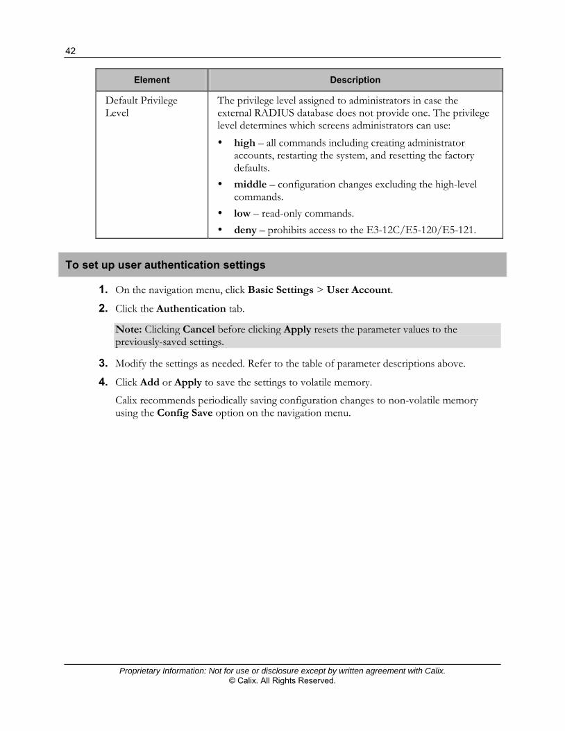
Default Privilege Level
The privilege level assigned to administrators in case the external RADIUS database does not provide one. The privilege level determines which screens administrators can use: high – all commands including creating administrator
accounts, restarting the system, and resetting the factory defaults.
middle – configuration changes excluding the high-level commands.
low – read-only commands. deny – prohibits access to the E3-12C/E5-120/E5-121.
To set up user authentication settings
1. On the navigation menu, click Basic Settings > User Account.
2. Click the Authentication tab.
Note: Clicking Cancel before clicking Apply resets the parameter values to the previously-saved settings.
3. Modify the settings as needed. Refer to the table of parameter descriptions above.
4. Click Add or Apply to save the settings to volatile memory.
Calix recommends periodically saving configuration changes to non-volatile memory using the Config Save option on the navigation menu.

43
Proprietary Information: Not for use or disclosure except by written agreement with Calix. © Calix. All Rights Reserved.
Upgrading System Software
This section describes how to manage the E3-12C/E5-120/E5-121 software for the following processes:
Upgrading to a new software version Downgrading to a previous software version
Calix strongly recommends backing up the E3-12C/E5-120/E5-121 configuration database before you perform either of the procedures included in this section.
Related topic
Backing Up the System Database (on page 47)
Performing a System Software Upgrade
This topic describes how to upgrade the E3-12C/E5-120/E5-121 to a new software release.
Calix strongly recommends that you back up the E3-12C/E5-120/E5-121 database before you perform the procedure in this section. Backing up the system database allows you to restore the current network configuration should you experience upgrade difficulties.
The software upgrade process has two main steps:
1. Download the new firmware file from the Calix Customer Resource Center at www.calix.com and unzip it.
2. Install the new software release. Rebooting the E3-12C/E5-120/E5-121 is required. You can either perform the reboot automatically after the firmware file finishes loading, or manually initiate the reboot.
ALERT! Be sure to install the correct model firmware. Installing the wrong model firmware may damage your device. Service affecting procedure. Perform upgrades during a standard maintenance window.

44
Proprietary Information: Not for use or disclosure except by written agreement with Calix. © Calix. All Rights Reserved.
To download the new firmware file
1. On the E3-12C/E5-120/E5-121 navigation menu, click Basic Settings > System Information to verify your current firmware version number.
2. Launch Internet Explorer and log in to the Calix Resource Center at www.calix.com.
Note: This procedure assumes your PC runs Microsoft Windows XP.
3. On the Calix Resource Center page, locate the Calix Software Center module as shown below to access E3-12C/E5-120/E5-121 software:
a. Click Request Software to obtain access to the latest software. Fill out and submit
the online request form.
b. Click the here link to go to the Software Center page, after you have obtained access to the software.
4. On the Software Center page, under the E5 Embedded System Software heading, click E3-12C/E5-120/E5-121 to load the listings.
5. Download the upgrade file as follows:
a. In the Name column, click the latest software release.
b. Note the software version number (x.x.x format). You will need this when you perform the upgrade to enable version checking.
c. Review the software right-to-use license agreement, and then click Accept.
d. At the download security warning, click Save to save the upgrade file to your PC.
6. When the file download completes, click Done.
Unzip the downloaded file.
45
Proprietary Information: Not for use or disclosure except by written agreement with Calix. © Calix. All Rights Reserved.
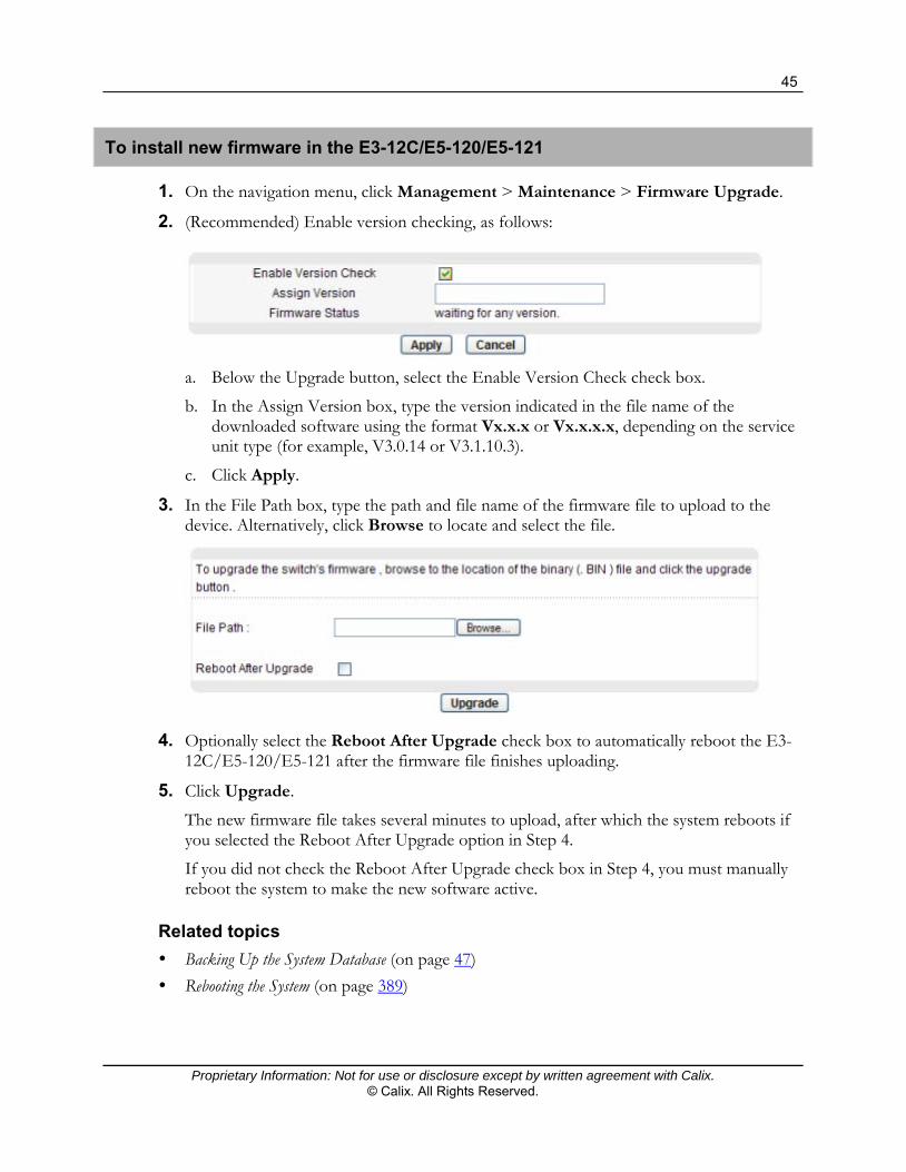
To install new firmware in the E3-12C/E5-120/E5-121
1. On the navigation menu, click Management > Maintenance > Firmware Upgrade.
2. (Recommended) Enable version checking, as follows:
a. Below the Upgrade button, select the Enable Version Check check box.
b. In the Assign Version box, type the version indicated in the file name of the downloaded software using the format Vx.x.x or Vx.x.x.x, depending on the service unit type (for example, V3.0.14 or V3.1.10.3).
c. Click Apply.
3. In the File Path box, type the path and file name of the firmware file to upload to the device. Alternatively, click Browse to locate and select the file.
4. Optionally select the Reboot After Upgrade check box to automatically reboot the E3-
12C/E5-120/E5-121 after the firmware file finishes uploading.
5. Click Upgrade.
The new firmware file takes several minutes to upload, after which the system reboots if you selected the Reboot After Upgrade option in Step 4.
If you did not check the Reboot After Upgrade check box in Step 4, you must manually reboot the system to make the new software active.
Related topics
Backing Up the System Database (on page 47) Rebooting the System (on page 389)

46
Proprietary Information: Not for use or disclosure except by written agreement with Calix. © Calix. All Rights Reserved.
Downgrading the System Software
You can downgrade to a previous firmware version. To do so, you must have the firmware file from a previous Calix download, or obtain the software file from Calix.
Important: Some system features may not be available in the lower software version. For this reason, after performing the following procedure, you should restore a database backup from when the system was running the software to which you are downgrading.
To downgrade to a previous firmware in the E3-12C/E5-120/E5-121
1. On the navigation menu, click Management > Maintenance > Firmware Upgrade.
2. In the File Path text box, type the path and file name of the previous firmware file to upload to the device. Alternatively, click Browse to locate and select it.
3. Click Upgrade.
Related topic
Restoring a Backup Database (on page 48)

47
Proprietary Information: Not for use or disclosure except by written agreement with Calix. © Calix. All Rights Reserved.
Performing Backup and Restore Operations
This section describes how to back up and restore the E3-12C/E5-120/E5-121 device configuration file.
Warning! Calix strongly recommends backing up the configuration file before you restore the default configuration.
The database backup process has two main steps:
1. Create a backup file of the current device configuration.
2. Transfer the backup file to a designated external file server.
The database restore process has two main steps:
1. Retrieve the previously archived device configuration backup file.
2. Replace the current device configuration with the retrieved backup file.
Backing Up the System Database
This topic describes how to back up the configuration file.
Backing up your device configuration creates a snapshot of your device which you can restore at a later time.
Note: Backing up the configuration file copies the last saved configuration file in non-volatile memory on the E3-12C/E5-120/E5-121; it does not copy the running configuration. Completing Step 2 in the following procedure saves the running configuration to non-volatile memory.
To back up the saved configuration file
1. If you are currently modifying settings on an E3-12C/E5-120/E5-121 configuration screen, click Apply to save the changes to run-time memory.
2. (Recommended) On the navigation menu, click Config Save.
3. On the navigation menu, click Management > Maintenance to open the Maintenance screen.
4. Do the following:
Click Backup Text Configuration.
Click Save.
- or -

48
Proprietary Information: Not for use or disclosure except by written agreement with Calix. © Calix. All Rights Reserved.
Right-click the Backup Text Configuration link.
Click Save Target As.
5. Select a directory location to save the file on your computer or network.
6. In the File name box, enter a descriptive name.
7. Click Save to save the configuration file.
Note: The configuration file is a simple text file with a “.dat” extension. You can change the extension of the file from “.dat” file to “.txt” file to upload it back to the E3-12C/E5-120/E5-121. For information about how to edit the configuration text file, see the Calix E3-12C/E5-120/E5-121 CLI User Guide.
Restoring a Backup Database
This topic describes how to load a configuration file from your computer to the device.
To restore a text configuration
1. On the navigation menu, click Management > Maintenance > Restore Text Configuration to open the Restore Configuration screen.
2. In the File Path text box, type the path and file name of the configuration file to restore.
Alternatively, click Browse to locate and select it.
3. Click Restore.
“config-0” is the name of the configuration file on the device, so your backup configuration file is automatically renamed when you restore using this screen.
WARNING! If you load an invalid configuration file, it may corrupt the settings, and you might have to use the console to reconfigure the system.

Proprietary Information: Not for use or disclosure except by written agreement with Calix. © Calix. All Rights Reserved.
Chapter 3
Configuring the Ethernet Links
This section includes the following topics:
Configuring the Ethernet port(s) Configuring RSTP Setting up the switch SIP VoIP traffic between subscribers on a daisy chain or RSTP ring
(E3-12C/E5-121 only)

50
Proprietary Information: Not for use or disclosure except by written agreement with Calix. © Calix. All Rights Reserved.
Configuring the Ethernet Port(s)
Use the ENET Port Setup screen to configure settings for the Ethernet ports.
Ethernet port configuration guidelines
Important: When operating E3-12C/E5-120/E5-121 service units in a daisy chain or ring configuration, Calix recommends using the same port speed on both Ethernet ports (1 Gbps or 100 Mbps).
When an Ethernet port is set to Auto, the E3-12C/E5-120/E5-121 attempts to make a fiber connection first and does not use the RJ-45 port if the fiber connection is successful.
The E3-12C/E5-120/E5-121 uses full duplex Ethernet connections.
To configure the Ethernet ports
1. In the Navigation menu, click Basic Settings > ENET Port Setup.
2. In the ENET Port Setup page, do the following for each port:
Note: Clicking Cancel before clicking Apply resets the fields to the currently-saved settings.
a. To turn on a port, select the Active check box. To disable a port, clear the check box.
b. In the Name box, type a descriptive name that identifies this port (up to 31 characters; spaces are not allowed).
c. In the Speed Mode box, select the type of Ethernet connection for this port:
Auto (auto-negotiation) automatically determines the type of connection. When the peer Ethernet device has auto-negotiation turned on, the E3-12C/E5-120/E5-121 negotiates with the peer to determine the connection speed. Otherwise, the E3-12C/E5-120/E5-121 detects the connection speed based on the cable signal.
100 Copper is applicable when the Ethernet port has a 100-Mbps electrical connection.
1000 Copper is applicable when the Ethernet port has a 1000-Mbps (1-Gigabit) electrical connection.
1000 Fiber is applicable when the Ethernet port has a 1000-Mbps (1-Gigabit) fiber optic connection.

51
Proprietary Information: Not for use or disclosure except by written agreement with Calix. © Calix. All Rights Reserved.
3. Click Add or Apply to save your changes to the system volatile memory.
4. (Recommended) On the navigation menu, use the Config Save option to save changes to non-volatile memory.
Configuring RSTP
This topic describes how to configure the Rapid Spanning Tree Protocol (RSTP) settings for the Ethernet ports (ENET1 and ENET2).
RSTP detects and breaks network loops and provides backup links between switches, bridges or routers, enabling a device to interact with other RSTP-aware devices in your network so that only one path exists between any two stations on the network.
For more information on RSTP, see the Calix E3-12C/E5-100 Engineering and Planning Guide and IEEE 802.1w.
Note: The E3-12C/E5-120/E5-121 cannot be the root bridge in an RSTP ring. Set the E3-12C/E5-120/E5-121 Bridge Priority value to the highest value allowed, and then ensure that the upstream switch has a lower Bridge Priority value.
To configure RSTP settings
1. In the Navigation menu, click Advanced Applications > RSTP.
2. Click the RSTP Config tab, and do the following:
Note: Clicking Cancel before clicking Add resets the screen parameters to the last-saved values.

52
Proprietary Information: Not for use or disclosure except by written agreement with Calix. © Calix. All Rights Reserved.
a. Select the Active check box to activate RSTP.
b. In the Bridge Priority box, type a value (0 to 65535, in 4096 increments) to determine the root bridge, root port, and designated port (which in turn determines Hello Time, Max Age and Forwarding Delay).
The switch with the highest priority (lowest numeric value) becomes the STP root switch. If all switches have the same priority, the switch with the lowest MAC address becomes the root switch.
c. In the Hello Time box, type the time interval (from 1 to 10 seconds) between Bridge Protocol Data Units (BPDU) configuration message generations by the root switch.
d. In the MAX Age box, type the maximum time (from 6 to 40 seconds) a switch can wait without receiving a BPDU before attempting to reconfigure.
All switch ports (except for designated ports) should receive BPDUs at regular intervals. Any port that ages out STP information (provided in the last BPDU) becomes the designated port for the attached network. If it is a root port, a new root port is selected from among the switch ports attached to the network.
e. In the Forwarding Delay box, type the maximum time (from 4 to 30 seconds) a switch waits before changing states.
This delay is required for every switch to receive information about topology changes before it starts to forward frames. In addition, each port has a time requirement for listening for conflicting information that would make it return to a blocking state; otherwise, temporary data loops might result.
As a general rule: 2 * (Forward Delay - 1) >= Max Age >= 2 * (Hello Time + 1)
f. For the Priority boxes, enter a value (from 0 to 255) that determines which port should be disabled when more than one port forms a loop in a switch. The default value is 128.
Ports with a higher priority numeric value are disabled first.
g. For the Path Cost boxes, enter a value (from 1 to 65535) that determines the cost of transmitting a frame on to a network through that port. The default value is 4.
The cost is assigned according to the speed of the bridge. The slower the media, the higher the cost.
3. Click Add or Apply to save the settings to volatile memory.
4. Calix recommends periodically saving configuration changes to non-volatile memory using the Config Save option on the navigation menu.

53
Proprietary Information: Not for use or disclosure except by written agreement with Calix. © Calix. All Rights Reserved.
RSTP Status Tab
Use the RSTP Status tab to display RSTP information, such as bridge status and port status of ENET1 and ENET2.
To open the RSTP Status tab
1. On the navigation menu, click Advanced Applications > RSTP.
2. Click the RSTP Status tab.
The following table describes the elements of the RSTP Status tab:
Element Description
RSTP Displays On if RSTP is activated. Otherwise, it displays Off.
Bridge Status If RSTP is activated, the following fields display. If RSTP is not activated, Disabled displays.
Our Bridge ID The unique identifier for this bridge, consisting of bridge priority plus MAC address. This ID is the same in Designated Root ID if the E3-12C/E5-120/E5-121 is the root switch.

54
Proprietary Information: Not for use or disclosure except by written agreement with Calix. © Calix. All Rights Reserved.
Element Description
Designated Root ID The unique identifier for the root bridge, consisting of bridge priority plus MAC address. This ID is the same in Our Bridge ID if the E3-12C/E5-120/E5-121 is the root switch.
Topology Change Times The number of times the spanning tree has been reconfigured.
Time Since Change The time since the spanning tree was last reconfigured.
Cost to Root The path cost from the root port on this switch to the root switch.
Root Port ID The priority and number of the port on the switch through which this switch must communicate with the root of the Spanning Tree. “0x0000” displays when this device is the root switch.
Root Max Age (second) The maximum time (in seconds) the root switch can wait without receiving a configuration message before attempting to reconfigure.
Root Hello Time (second) The time interval (in seconds) at which the root switch transmits a configuration message. The root bridge determines Hello Time, Max Age and Forwarding Delay.
Root Forward Delay (second)
The time (in seconds) the root switch will wait before changing states (that is, listening to learning to forwarding).
Max Age (second) The maximum time (in seconds) the E3-12C/E5-120/E5-121 can wait without receiving a configuration message before attempting to reconfigure.
Hello Time (second) The time interval (in seconds) at which the E3-12C/E5-120/E5-121 transmits a configuration message. The root bridge determines Hello Time, Max Age and Forwarding Delay.
Forward Delay (second) The time (in seconds) the E3-12C/E5-120/E5-121 waits before changing states (that is, listening to learning to forwarding).
Port Status Identifies the E3-12C/E5-120/E5-121 ports that support the use of RSTP. If RSTP is activated, the following fields display. If RSTP is not activated, Disabled displays.

55
Proprietary Information: Not for use or disclosure except by written agreement with Calix. © Calix. All Rights Reserved.
Element Description
State The port’s RSTP state. With RSTP, the state can be discarding, learning or forwarding.
Disabled displays when RSTP has not been turned on for the individual port or the whole device.
Port ID The priority and number of the port on the switch through which this switch must communicate with the root of the Spanning Tree. “0x0000” displays when this device is the root switch.
Path Cost The path cost from this port to the root switch.
Cost to Root The path cost from the root port on this switch to the root switch.
Designated Bridge The unique identifier for the bridge that has the lowest path cost to reach the root bridge, consisting of bridge priority plus MAC address.
Designated Port The port on the designated bridge that has the lowest path cost to reach the root bridge, consisting of bridge priority.
Poll Interval(s)
Set Interval
Displays how often (in seconds) this screen refreshes. You may change the refresh interval by typing a new number in the text box and then clicking Set Interval.
Stop Click Stop to halt RSTP statistic polling.

56
Proprietary Information: Not for use or disclosure except by written agreement with Calix. © Calix. All Rights Reserved.
Link Aggregation (IEEE 802.3ad)
For standalone service units that are not part of an RSTP ring, you can group Ethernet ports into a trunk to increase the uplink bandwidth using the Link Aggregation feature.
For more information, see the Calix E3-12C/E5-100 Engineering and Planning Guide.
Configuring Aggregation
Use the Link Aggregation (IEEE 802.3ad) configuration screen to configure IEEE 802.3ad link aggregation settings.
Calix E3-12C, E5-120, and E5-121 service units support both static and dynamic link aggregation.
Note the following guidelines for Link Aggregation Control Protocol (LACP).
Configuration guidelines for LACP
You must connect all ports point-to-point to the same Ethernet switch and configure the ports for LACP trunking.
LACP only works on full-duplex links. All ports in the same trunk group must have the same media type, speed, duplex mode,
and flow control settings. To avoid causing network topology loops, configure trunk groups or LACP before you
connect the service unit.
To open the Link Aggregation (802.3ad) Config tab
1. On the navigation menu, click Advanced Applications > Link Aggregation (IEEE 802.3ad).
2. Click the Config tab.

57
Proprietary Information: Not for use or disclosure except by written agreement with Calix. © Calix. All Rights Reserved.
The following table describes the labels in the Dot3ad Config tab:
Label Description
Link Aggregation Mode
Select the mode:
LACP – Aggregation with LACP. Use this setting to dynamically create and manage the trunk group.
Static – Aggregation without LACP. Use this setting to have the E3-12C/E5-120/E5-121 add the two Ethernet ports into a trunk group.
Disable – Use this setting to disable link aggregation on the E3-12C/E5-120/E5-121.
Apply Click Apply to save the link aggregation mode setting.
LACP Priority Enter a number (0 to 65535) for the LACP system priority. The E3-12C/E5-120/E5-121 with the lowest system priority (and lowest port number if the system priority is the same) becomes the LACP "server." The LACP server controls the LACP setup operation.
Note: Calix recommends configuring the E3-12C/E5-120/E5-121 at a higher priority than the uplink Ethernet switch in order for the uplink switch to be the master.
LACP Timeout The time interval between the individual port exchanges of LACP packets in order to check that the peer port in the trunk group is operational. If a port does not respond after three attempts, it is considered “down” and is removed from the trunk.
Enter either short (1-second timeout) or long (30-second timeout). Set a short timeout for busy trunked links to ensure that disabled ports are removed from the trunk as soon as possible. The default is long.
Note: Calix recommends setting both the E3-12C/E5-120/E5-121 and the uplink Ethernet switch to the same LACP timeout value.
Apply Click Apply to save the LACP settings.

58
Proprietary Information: Not for use or disclosure except by written agreement with Calix. © Calix. All Rights Reserved.
Viewing Link Aggregation Status
The Status tab provides Link Aggregation LACP information.
To view the Link Aggregation status
1. On the navigation menu, click Advanced Applications > Link Aggregation (802.3ad).
2. Click the Status tab.
The following table describes the labels in the Status tab:
Label Description
State Displays the link aggregation mode (type): LACP – Aggregation with LACP Static – Aggregation without LACP Disable
Members Displays the member ports.
Links Displays the trunk member ports that have been added to the LACP group.
Syncs Ports that have successfully negotiated with port at the peer end in the LACP group.

59
Proprietary Information: Not for use or disclosure except by written agreement with Calix. © Calix. All Rights Reserved.
Setting Up the Switch
This topic describes how to configure E3-12C/E5-120/E5-121 switch settings.
The Switch Setup screen enables you to set up and configure global device features.
To setup an E3-12C/E5-120/E5-121 switch
1. In the Navigation menu, click Basic Settings > Switch Setup.
2. In the Switch Setup page, do the following:
Note: Clicking Cancel before clicking Apply resets the fields to the currently-saved settings.
a. In the MAC Address Learning Aging Time box, type a time from 10 to 10,000 seconds to control how long all dynamically learned MAC addresses remain in the MAC address table before they age out (and must be relearned). Enter 0 to disable the aging out of MAC addresses.
b. Select the Port Isolation Active check box to turn on port isolation and block communications between subscriber ports.
When the Port Isolation check box is cleared, a "VLAN Isolation" link displays where you can optionally configure VLANs to isolate subscribers (see the procedure, "To Manage VLAN Isolation," below).
c. In the MAC Anti-Spoofing check box, select to have the E3-12C/E5-120/E5-121 generate an alarm and issue a SNMP trap when a MAC address is connected to more than one port.
d. In the Priority Queue Assignment boxes, configure the priority level-to-physical queue mapping.

60
Proprietary Information: Not for use or disclosure except by written agreement with Calix. © Calix. All Rights Reserved.
IEEE 802.1p defines up to eight separate traffic types to define class of service. Frames without an explicit priority tag are given the default priority of the ingress port. Traffic assigned to higher index queues gets through the device faster while traffic in lower index queues is dropped if the network is congested. Examples of common priority usage are listed below:
Priority 7—network control traffic such as router configuration messages.
Priority 6—voice traffic that is especially sensitive to jitter (jitter is the variations in delay).
Priority 5—video that consumes high bandwidth and is sensitive to jitter.
Priority 4—controlled load, latency-sensitive traffic such as Systems Network Architecture (SNA) transactions.
Priority 3—“excellent effort” or better than best effort and would include important business traffic that can tolerate some delay.
Priority 2—spare bandwidth.
Priority 1—non-critical “background” traffic such as bulk transfers that are allowed but that should not affect other applications and users.
Priority 0—best-effort traffic.
e. In the Tag Protocol Identifier box, type the four digits in the hexadecimal protocol ID to use together with the VLAN (including priority) tag for managing traffic. By default, 8100 is used (for 0x8100, or Ethernet traffic). The E3-12C/E5-120/E5-121 accepts tagged traffic with the specified protocol ID and drops tagged traffic if the protocol ID does not match.
3. Click Add or Apply to save your changes to the system volatile memory.
4. (Recommended) On the navigation menu, use the Config Save option to save changes to non-volatile memory.

61
Proprietary Information: Not for use or disclosure except by written agreement with Calix. © Calix. All Rights Reserved.
To manage VLAN isolation
1. On the navigation menu, click Basic Settings > Switch Setup.
2. In the Switch Setup screen, clear the Port Isolation check box and click the VLAN Isolation hyperlink.
3. In the VID box, type a VLAN ID to isolate, and then click Add to add the VLAN ID to the VLAN Isolation list.
4. Repeat Step 3 for each VLAN you are isolating.
5. Click Up to return to the Switch Setup screen.
6. To delete one or more VLANs from the VLAN isolation list, select the check box in the Select column for an entry, and then click Delete. Clicking All selects all VLANs in the list. Clicking None clears all of the check boxes.

62
Proprietary Information: Not for use or disclosure except by written agreement with Calix. © Calix. All Rights Reserved.
Setup Note: External Media Gateway for SIP VoIP Traffic (E3-12C and E5-121)
To pass any traffic between a subscriber on one E3-12C or E5-121 in a daisy chain or RSTP ring to a subscriber on a different service unit on the same daisy chain or RSTP ring, traffic must be routed through the upstream switch (via the ENET1 port) for redirection back to the subtended unit.
For E3-12C or E5-121 SIP VoIP service, completing a call between subscribers on different service units in the same daisy chain or RSTP ring requires that voice traffic is routed through an external media gateway. On a Metaswitch softswitch, for example, this is enabled with the "Restricted Direct Media" option in the gateway model.
Note: This setup requirement does not apply to VoIP services using a C7 TDM Gateway.
If you cannot route SIP calls through an external media gateway, you must configure each E3-12C or E5-121 VoIP interface in the daisy chain or ring with a unique IP subnet (and the router must be configured accordingly). In this setup, each E3-12C or E5-121 detects that the RTP endpoint is on a different subnet and sends packets upstream, passing them back down to the other unit.

Proprietary Information: Not for use or disclosure except by written agreement with Calix. © Calix. All Rights Reserved.
Chapter 4
Creating System Profiles
This section describes how to create profiles required for configuring data, video, and VoIP services. The profiles consist of a list of definable settings that you can assign to one or more individual ports to manage bandwidth and prioritize traffic based on subscribers' service plans and requirements.
Topics Covered
This section covers the following topics and tasks:
Creating service profiles Creating traffic management profiles Creating VoIP service profiles (E3-12C/E5-121 only)

64
Proprietary Information: Not for use or disclosure except by written agreement with Calix. © Calix. All Rights Reserved.
Creating Service Profiles
This section describes how to create IGMP, xDSL, IP Quality of Service (IP QoS), and xDSL alarm profiles that streamline the configuration of xDSL ports for service.
Creating IGMP Profiles
Use the IGMP Profile screen to define IGMP profiles and the IGMP Profile Map screen to assign them to specific xDSL ports.
IGMP profiles to control access to a service that uses a specific multicast group. Configure an IGMP profile that allows access to that multicast group. Then assign the IGMP profile to xDSL subscriber ports that are allowed to use the service.
Note: The video provisioning model in R3.x eliminates the need to create a channel lineup and specify bandwidth-per-channel requirements.
Note: Multicast services can be enabled and disabled on a per-port basis.
The IGMP profile must include all multicast IP addresses that the E3-12C/E5-120/E5-121 will be receiving traffic on (video and middleware). This prevents an STB from tuning to invalid multicast IP addresses and causing undue congestion to IGMP counters.
By default, the AllVideoService profile is assigned to all DSL ports to enable joining all multicast IP addresses (224.0.0.0 through 239.255.255.255). To restrict DSL subscriber access to specific IGMP multicast groups, create a different profile and assign it to the DSL port in the IGMP Profile Map screen.
The top of the IGMP Profile screen displays the configured IGMP profiles. The bottom part of the screen is used for adding or modifying profiles.

65
Proprietary Information: Not for use or disclosure except by written agreement with Calix. © Calix. All Rights Reserved.
Note: You can edit but cannot delete the default profiles.
To define an IGMP profile
1. On the navigation menu, click Advanced Applications > IGMP.
2. Click the Profile tab, and then do the following:
a. In the Name field, type a name for the profile (up to 30 characters; spaces are permitted).
b. Select the Active check box to enable multicast service.
c. In the Max Group box, type the maximum multicast groups allowed for the profile (1 to 64).
d. In the row to the right of the index for the profile that you are creating or editing, type the Start IP and End IP address, to define a range of multicast addresses.
Note: For one multicast address, enter the same multicast range in the Start IP and End IP fields.
e. At the bottom of the work area, click Add.
The new profile displays in the list at the top of the screen.
3. Repeat Step 2 for each profile you are creating.
To modify an IGMP profile
1. On the navigation menu, click Advanced Applications > IGMP.
2. Click the Profile tab.
3. In the list of profiles, under the Index column, click the link for the profile you are editing to load the profile settings in the lower half of the screen.
4. Edit the profile settings per site requirements.
5. At the bottom of the screen, click Modify.
To delete an IGMP profile
1. On the navigation menu, click Advanced Applications > IGMP.
2. Click the Profile tab.
3. In the profile list, under the Delete column, select the check box for each profile you are deleting.
4. Below the profile list, click Delete.
See also: Assign IGMP Profiles to xDSL Ports (on page 66).

66
Proprietary Information: Not for use or disclosure except by written agreement with Calix. © Calix. All Rights Reserved.
Assigning IGMP Profiles to xDSL Ports
For a checklist of provisioning steps, see the Video Provisioning Checklist (on page 151).
After creating IGMP profiles, use the IGMP Profile Map screen to assign them to xDSL ports.
To assign an IGMP profile to xDSL port(s)
1. On the navigation menu, click Advanced Applications > IGMP.
Click the Profile Map tab.
2. In the Profile Map tab, do the following:
a. In the Profile list in the row of one of the ports you are assigning, click the profile to use.
b. At the bottom of the work area, click Apply.
3. To copy the profile to other ports:
a. At the bottom of the work area, click the port number with the profile to copy, and then click Paste.
b. In the popup dialog box, click the check boxes of the port number(s) to which you are copying the profile. Click All to select all ports (clicking None clears the check boxes).
c. At the bottom of the work area, click Apply.

67
Proprietary Information: Not for use or disclosure except by written agreement with Calix. © Calix. All Rights Reserved.
xDSL Profiles
An xDSL profile is a group of pre-configured xDSL settings that are applied to individual xDSL ports to manage bandwidth and prioritize traffic based on subscribers' service plans and requirements. Each xDSL port has one (and only one) profile assigned to it at any given time.
Configure all xDSL ports with the same profile, eliminating the need to configure ports individually.
Change individual xDSL port by assigning it a different xDSL profile.
For example:
1. Set up different profiles for different accounts (economy, standard, and premium).
2. Assign the appropriate profile to an xDSL port to automatically provision the port maximum and minimum transfer rates.
3. Individually enable or disable each port and configure the channels and operational mode.
Note: By default, the DEFVAL profile is assigned to each xDSL port until you change it.
In addition to setting the minimum and maximum upstream and downstream rates, when you create an xDSL profile, you select the latency mode (interleave or fast) and the signal-to-noise ratio (SNR) values.
Interleave mode
Interleave delay is the wait (in milliseconds) that determines the size of a single block of data to be interleaved (assembled) and then transmitted. Interleave delay is used when transmission error correction (Reed-Solomon) is necessary due to a less than ideal telephone line. The longer the delay, the larger the data block size sent, allowing for better error correction.
Reed-Solomon codes are block-based error correcting codes with a wide range of applications. The Reed-Solomon encoder takes a block of digital data and adds extra "redundant" bits. The Reed-Solomon decoder processes each block and attempts to correct errors and recover the original data.
Fast mode
Fast mode means no interleaving takes place and transmission is faster (a “fast channel”). Fast mode is suitable when you have a good line and little error correction is necessary.

68
Proprietary Information: Not for use or disclosure except by written agreement with Calix. © Calix. All Rights Reserved.
Signal-to-Noise Ratio (SNR) Settings
The following table describes the SNR fields:
SNR Field Description
Maximum and Minimum SNR
SNR is the measurement of the signal relative to undesired noise. As a reflection of the "robustness" of a connection, a higher SNR value indicates better signal quality.
Target SNR The SNR value used in conjunction with the up shift and down shift SNR values (see below) to optimize the data transfer rate.
Up Shift SNR The SNR above which the device attempts to use a higher transfer rate. Use an up shift SNR that is greater than or equal to the target SNR and less than or equal to the maximum SNR.
Down Shift SNR The SNR below which the device shifts to a lower transfer rate. Use a down shift SNR that is less than or equal to the target SNR and greater than or equal to the minimum SNR.
Considerations for setting SNR values:
For video applications: Calix recommends achieving and maintaining an actual downstream SNR margin of at least 8 dB. A connection with an SNR margin of less than 8 dB runs the risk of tiling, macroblocking, and yielding sub-standard video quality. In addition, setting the upshift SNR equal to the maximum SNR and the downshift SNR equal to the minimum SNR disables the seamless rate adaption (SRA) feature.
For data applications: Setting the minimum SNR value at or close to 0 minimizes the occurrence of modem re-trains.
Related topic
To override the xDSL profile SNR values on a per-port basis based on site requirements, see SNR Margin screen (on page 237).

69
Proprietary Information: Not for use or disclosure except by written agreement with Calix. © Calix. All Rights Reserved.
Creating xDSL Profiles
Use the xDSL Profile screen to create a group of pre-configured xDSL settings for applying to individual xDSL ports to manage bandwidth and prioritize traffic.
The following illustration shows the xDSL Profile screen.
The top half of the screen lists the configured xDSL profiles. The bottom half of the screen is where you add or edit an xDSL profile.
To create an xDSL port profile
1. In the Navigation menu, click Basic Settings > xDSL Profiles Setup.
2. In the xDSL Profile tab page, do the following:
Note: Clicking Cancel resets the screen settings without saving.
a. In the Name box, type a descriptive name for the profile (up to 31 characters; spaces and dashes are not permitted). Example: 2.5meg.
b. In the Latency Mode list, select the mode (Fast or Interleave) for the ports that belong to this profile.

70
Proprietary Information: Not for use or disclosure except by written agreement with Calix. © Calix. All Rights Reserved.
c. In the Max Rate Up Stream box and Max Rate Down Stream box, type the maximum upstream (64 to 4096 Kbps) and maximum (64 to 32000 Kbps) downstream transfer rate.
The maximum upstream transfer rate must be less than the maximum downstream transfer rate.
d. In the Min Rate Up Stream box and Min Rate Down Stream box, type the minimum upstream (32 to 4096 Kbps) and minimum (32 to 32000 Kbps) downstream transfer rate for the ports that belong to this profile.
The upstream and downstream minimum transfer rates must be less than the corresponding maximum transfer rates.
e. In the Interleave Delay box, type the number of milliseconds (1 to 255) of interleave delay to use for upstream and downstream transfers. Configure this field when you set the Latency Mode field to Interleave.
Note: Calix recommends configuring the same latency delay for both upstream and downstream traffic.
f. In the Max Signal-to-Noise (SNR) box, type the maximum upstream and downstream SNR values (0 to 31 dB).
g. In the Min SNR box, type the minimum upstream SNR (0 to 31 dB).
The minimum upstream and downstream SNR values must be less than or equal to the corresponding maximum SNR values.
h. In the Target SNR box, type the target upstream SNR margin (0 to 31 dB).
The target upstream and downstream SNR values must be greater than or equal to the corresponding minimum SNR values and less than or equal to the corresponding maximum SNR values.
i. In the Up Shift SNR box, type the up shift SNR (0 to 31 dB).
j. In the Down Shift SNR box, type the Down shift signal-to-noise margin (0 to 31 dB).
3. Click Add or Apply to save the settings to volatile memory.
4. Calix recommends periodically saving configuration changes to non-volatile memory using the Config Save option on the navigation menu.
The profile name and corresponding index number display in the list of xDSL Profiles.
To modify a profile
Note: You cannot modify the DEFVAL profile. To change the name of a profile, you must create a new one and assign it to the subscriber ports where you are using it.
1. To the right of the profile listing you are modifying, select the Select radio button.
2. Click Modify.

71
Proprietary Information: Not for use or disclosure except by written agreement with Calix. © Calix. All Rights Reserved.
3. Scroll to the bottom of the screen and update the parameter values that you are changing.
4. Click Apply.
To delete a profile
Note: You cannot delete the DEFVAL profile.
1. To the right of the profile listing you are deleting, select the Select radio button.
2. Click Delete.
Sample xDSL Profiles
Example: VDSL data-only profile
The following is an example of a VDSL profile providing 8 Mbps data traffic downstream and 768 Kbps upstream.

72
Proprietary Information: Not for use or disclosure except by written agreement with Calix. © Calix. All Rights Reserved.
Example: ADSL fallback data-only profile
The following is an example of an xDSL profile providing 2.5 Mbps data traffic downstream and 768 Kbps upstream.
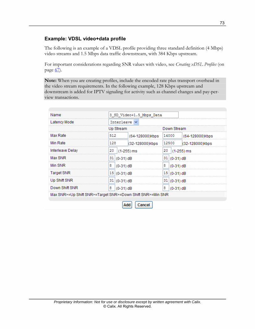
73
Proprietary Information: Not for use or disclosure except by written agreement with Calix. © Calix. All Rights Reserved.
Example: VDSL video+data profile
The following is an example of a VDSL profile providing three standard definition (4 Mbps) video streams and 1.5 Mbps data traffic downstream, with 384 Kbps upstream.
For important considerations regarding SNR values with video, see Creating xDSL Profiles (on page 67).
Note: When you are creating profiles, include the encoded rate plus transport overhead in the video stream requirements. In the following example, 128 Kbps upstream and downstream is added for IPTV signaling for activity such as channel changes and pay-per-view transactions.

74
Proprietary Information: Not for use or disclosure except by written agreement with Calix. © Calix. All Rights Reserved.
Creating IP QoS Profiles
This topic describes how to create IP Quality of Service (QoS) for each data service plan to ensure consistent Internet data rate.
Without QoS, all traffic data is equally likely to be dropped when the network is congested, potentially reducing network performance and making the network inadequate for time-critical applications such as video-on-demand.
Configure a IP QoS to group and prioritize application traffic in queues for downstream direction (toward CPE devices) and fine-tune network performance.
The following illustration shows the IP QoS Profile screen.
The top half of the screen lists the configured IP QoS profiles. The bottom half of the screen is where you add or edit a IP QoS profile.

75
Proprietary Information: Not for use or disclosure except by written agreement with Calix. © Calix. All Rights Reserved.
The following table provides information about each parameter for creating an IP QoS profile.
Element Description
Name Description identifying the IP QoS profile.
Number of Queues The number of queues used to classify traffic. Select 1, 2, 4 or 8 queues in an IP QoS profile depending on the number of applications you are classifying.
Important Note: Calix strongly recommends using 8 queues for traffic classification and prioritization.
Queue Id The index number of queues listed in the following table according to the selection in the Number of Queues field.
PIR The Peak Information Rate is the maximum data rate allowed to flow through the device (from 512 to 131,072 Kbps, in 256-Kbps increments).
CIR The Committed Information Rate is the maximum data rate guaranteed to flow through this device all the time (from 255 to 65536 Kbps, in 256-Kbps increments).
Note: In the same queue, the PIR must be less than or equal to two times the value of the CIR. For example, if the CIR is 1024, you must enter a PIR in the same queue less than or equal to 2048 (2 x 1024).
PBS The Peak Burst Size is the maximum burst size allowed for downstream traffic flowing through the device when the burst data rate is between the predefined PIR and CIR (from 3072 to 65536 bytes, in 256-Kbps increments).
CBS The Committed Burst Size is the maximum burst size guaranteed for downstream traffic flowing through the device when the burst data rate is smaller than the predefined CIR (from 3072 to 65536 bytes, in 256-Kbps increments).
Note: The CBS should be less than or equal to the PBS in a queue.
Level The Level parameter defines the scheduling priority for the traffic classes (7 is the highest priority).
Weight The Weight parameter is used for bandwidth distribution if multiple traffic classes have the same level. The bandwidth distribution is based on the weighted round robin (WRR) best-effort connection scheduling discipline.

76
Proprietary Information: Not for use or disclosure except by written agreement with Calix. © Calix. All Rights Reserved.
To create an IP QoS profile
1. On the navigation menu, click Basic Settings > xDSL Profiles Setup.
2. Click the IPQoS Profile tab.
3. In the IPQos Profile page, do the following:
Note: Clicking Cancel resets the screen settings without saving.
a. In the Name box, type a descriptive name for the profile (up to 31 characters in length; spaces and dashes are not permitted). When you create an IP QoS profile, an index number is automatically assigned to the IP QoS profile.
b. In the Number of Queues list, select the number of the number of queues used to classify traffic.
Select 1, 2, 4, or 8 queues in an IP QoS profile depending on the number of applications to classify. Calix strongly recommends using 8 queues for traffic classification and prioritization.
c. For each queue ID, do the following:
In the PIR field, type the Peak Information Rate (from 512 to 131072 Kbps, in 256-Kbps increments).
In the CIR field, type the Committed Information Rate (from 255 to 65536 Kbps, in 256-Kbps increments).
Note: In the same queue, the PIR must be less than or equal to two times the value of the CIR. For example, if the CIR is 1024, you must enter a PIR in the same queue less than or equal to 2048 (2 x 1024).
In the PBS field, type the Peak Burst Size (from 3072 to 65536 bytes, in 256-Kbps increments).
In the CBS field, type the Committed Burst Size (from 3072 to 65536 bytes, in 256-Kbps increments).
Note: The CBS must be less than or equal to the PBS in a queue.
In the Level field, type the scheduling priority for the traffic classes (7 is the highest priority).
In the Weight field, type the bandwidth distribution if multiple traffic classes have the same level. The bandwidth distribution is based on the weighted round robin (WRR) best-effort connection scheduling discipline.
4. Click Add or Apply to save your changes to the system volatile memory.
5. (Recommended) On the navigation menu, use the Config Save option to save changes to non-volatile memory.
The IP QoS profile displays in the table of profiles.

77
Proprietary Information: Not for use or disclosure except by written agreement with Calix. © Calix. All Rights Reserved.
To modify a profile
Note: You cannot modify the DEFVAL profile. To change the name of a profile, you must create a new one and assign it to the subscriber ports where you are using it.
1. To the right of the profile listing you are modifying, select the Select radio button.
2. Click Modify.
3. Scroll to the bottom of the screen and update the parameter values that you are changing.
4. Click Apply.
To delete a profile
Note: You cannot delete the DEFVAL profile.
1. To the right of the profile listing you are deleting, select the Select radio button.
2. Click Delete.
Creating xDSL Alarm Profiles
This topic describes how to create xDSL alarm profiles that define ADSL port alarm thresholds. The E3-12C/E5-120/E5-121 sends an alarm trap and generates a syslog entry when the thresholds of the alarm profile are exceeded.
Until you assign ports to an alarm profile, the DEFVAL profile is used (with all alarm profile parameters set to 0). Use this procedure to create a new alarm profile and assign xDSL ports.
The top part of the page (with the Apply and Cancel buttons) displays the currently-select alarm profile (see the procedure below for how to modify or delete a profile). The rest of the page displays the configured alarm profiles and port assignments.

78
Proprietary Information: Not for use or disclosure except by written agreement with Calix. © Calix. All Rights Reserved.
To open the Alarm Profile screen
1. On the navigation menu, click Basic Settings > xDSL Profiles Setup.
2. Click the Alarm Profile tab.
3. In the Alarm Profile page, do the following:
Note: Clicking Cancel resets the screen settings without saving.
a. In the Name box, type a descriptive name for the profile (up to 31 characters; spaces and dashes are not permitted).
b. In the Threshold column, specify limits for individual performance counters. The E3-12C/E5-120/E5-121 sends an alarm trap and generates a syslog entry when one of these thresholds is exceeded. Type a value of 0 to disable an alarm threshold.
In the 15 Min LOF box, set the limit for the number of Loss Of Frame seconds that are permitted to occur within 15 minutes.
In the 15 Min LOS box, set the limit for the number of Loss Of Signal seconds that are permitted to occur within 15 minutes.
In the 15 Min LOL box, set the limit for the number of Loss Of Link seconds that are permitted to occur within 15 minutes.
In the 15 Min LPR box, set the limit for the number of Loss of Power seconds (on the ATUR) that are permitted to occur within 15 minutes.

79
Proprietary Information: Not for use or disclosure except by written agreement with Calix. © Calix. All Rights Reserved.
In the 15 Min ES (seconds) box, set the limit for the number of Errored Seconds that are permitted to occur within 15 minutes.
In the 15 Min SESL (seconds) box, set the limit for the number of Severely Errored seconds (line) that are permitted to occur within 15 minutes.
In the 15 Min UASL (seconds) box, set the limit for the number of Unavailable seconds (line) that are permitted to occur within 15 minutes.
c. To trigger an alarm for an initialization failure trap, select the Init Failure Trap check box.
4. Click Add or Apply to save your changes to the system volatile memory.
5. (Recommended) On the navigation menu, use the Config Save option to save changes to non-volatile memory.
To assign port(s) to a profile
1. Refer to the table above the first profile map to view the port numbering legend.
2. Scroll down to locate the alarm profile map. Click a port number’s "-" symbol to map the xDSL port to the alarm profile.
In the alarm profile map, the "-" symbol changes to "V", and the port location for a previously-assigned profile changes from a "V" to a "-".
To modify an alarm profile
Note: You cannot modify the DEFVAL profile. To change the name of an alarm profile, you must create a new profile and assign ports to it.
1. In the alarm profile map heading, click Modify.
2. At the top of the page, after making changes to the profile parameter values, click Apply.
To delete an alarm profile
Note: You cannot delete the DEFVAL profile, or any profile that has ports assigned to it.
1. In the alarm profile map heading, click Delete.

80
Proprietary Information: Not for use or disclosure except by written agreement with Calix. © Calix. All Rights Reserved.
Creating Traffic Management Profiles
This section describes how to create device profiles that manage traffic for services on xDSL ports.
The E3-12C/E5-120/E5-121 provides differentiated services delivery by classifying traffic flows based on service profiles, using Ethernet Priority class (IEEE 802.1p bits), queuing, and scheduling for traffic prioritization.
Creating ACL Profiles
This topic describes how to create an Access Control Logic (ACL) profile.
An ACL profile is assigned to PVCs or VDSL ports to use one of 17 numbered rules to classify upstream traffic and then perform specified actions on the upstream traffic. Each ACL profile consists of a rule and an action.
Up to eight ACL profiles can be assigned to a single PVC or VDSL port.
ACL profile actions
The E3-12C/E5-120/E5-121 can perform the following actions after it classifies upstream traffic:
rate: change the rate to the specified value (1 to 65535 Kbps) new vlan: change the VLAN ID to the specified value (1 to 4094) priority: change the IEEE 802.1p priority to the specified value (0 to 7) deny: do not forward the packet
Upstream you must use an ACL to tier and prioritize rates. For example:
One ACL profile acts on the video or E3-12C/E5-121 VoIP VLAN, giving it a higher queue priority than data.
Another ACL profile acts on the data VLAN, limiting the rate to a certain amount so as to ensure some amount of upstream bandwidth is always available for video channel change, VOD session initiation, and such
Note: The E3-12C/E5-120/E5-121 can apply multiple actions to a packet, unless you select deny.
If you select the new VLAN (replace VLAN) action, the E3-12C/E5-120/E5-121 replaces the VLAN ID before it compares the VLAN ID of the packet to the VID of the PVC. If you replace the VLAN ID for a normal PVC, the E3-12C/E5-120/E5-121 drops the traffic because the new VLAN ID does not match the VID of the PVC.

81
Proprietary Information: Not for use or disclosure except by written agreement with Calix. © Calix. All Rights Reserved.
For example, for a normal PVC with a PVID of 900, you can create an ACL rule to replace the VLAN ID with 901. Initially the traffic for the PVC belongs to VLAN 900. Then, the E3-12C/E5-120/E5-121 checks the ACL rule and changes the traffic to VLAN 901. When the E3-12C/E5-120/E5-121 compares the VLAN ID of the traffic (901) to the VID of the PVC (900), it drops the packets because they do not match.
Applying multiple profiles to a PVC
If you apply multiple profiles to a PVC, the E3-12C/E5-120/E5-121 checks the profiles by rule number. The lower the rule number, the higher the priority the rule (and profile) has.
For example, if there are two ACL profiles assigned to a PVC, Profile1 is for VLAN ID 100 (rule number 9) traffic, and Profile2 is for IEEE 802.1p priority 0 traffic (rule number 12). The E3-12C/E5-120/E5-121 checks Profile1 first. If the traffic is VLAN ID 100, the E3-12C/E5-120/E5-121 follows the action in Profile1 and does not check Profile2.
Note: You cannot assign profiles that have the same rule numbers to the same PVC.

82
Proprietary Information: Not for use or disclosure except by written agreement with Calix. © Calix. All Rights Reserved.
To create an ACL profile
1. On the navigation menu, click Advanced Applications > ACL > ACL Profile.
2. In the Profile Name box, type a descriptive name for the profile (up to 31 characters in length; spaces and dashes are not permitted).
3. In the Rule section, select the type of rule to use and then provide additional information required for the selection.
For rule #1, enter the 16-bit EtherType value (0 to 65535), and then enter a VLAN ID (1 to 4094).
For rule #2, enter the 16-bit EtherType value (0 to 65535), and then enter the source MAC address.
For rule #3, enter the 16-bit EtherType value (0 to 65535), and then enter the destination MAC address.
For rule #4, enter a VLAN ID (1 to 4094), and then enter the source MAC address.
For rule #5, enter a VLAN ID (1 to 4094), and then enter the destination MAC address.
For rule #6, enter the source MAC address, and then enter the destination MAC address.
For rule #7, enter a VLAN ID (1 to 4094), and then select the IEEE 802.1p priority (0 to 7).
For rule #8, enter the 16-bit EtherType value (0 to 65535).
For rule #9, enter a VLAN ID (1 to 4094).
For rule #10, enter the source MAC address.
For rule #11, enter the destination MAC address.
For rule #12, select the IEEE 802.1p priority (0 to 7).
For rule #13, in the Protocol list, select the IP protocol type or select "-" and type the protocol number used (0 to 255).
For rule #14, enter a VLAN ID (1 to 4094), and then enter the source IP address.
For rule #15, enter a VLAN ID (1 to 4094), and then enter the destination IP address.
For rule #16, enter a VLAN ID (1 to 4094), select the protocol (TCP or UDP), and then enter the source port (1 to 65335).
For rule #17, enter a VLAN ID (1 to 4094), select the protocol (TCP or UDP), and then enter the destination port (1 to 65335).

83
Proprietary Information: Not for use or disclosure except by written agreement with Calix. © Calix. All Rights Reserved.
4. In the Action section, select the check box(es) for which action(s) the E3-12C/E5-120/E5-121 should follow when the criteria are satisfied, and then enter additional required information.
For Rate, enter the maximum bandwidth allowed for this traffic.
For New VLAN, enter the VLAN ID that this traffic should use.
For New priority, select the IEEE 802.1p priority for this traffic.
For Deny, select this check box if you want the E3-12C/E5-120/E5-121 to reject this kind of traffic.
5. Click Add or Apply to save your changes to the system volatile memory.
6. (Recommended) On the navigation menu, use the Config Save option to save changes to non-volatile memory.
The profile name and corresponding index number appear in the list of ACL Profiles.
In the Type column, the PVC displays for an ADSL port, and an "*" displays for a VDSL port.
To modify an ACL profile
1. On the navigation menu, click Advanced Applications > ACL > ACL Profile.
2. Click the Index number of the profile that you are modifying.
3. Using the options under Steps 3 and 4 in the preceding procedure, update the profile per site requirements.
4. Below the list of ACL profile settings, click Apply.
To delete an ACL profile
1. On the navigation menu, click Advanced Applications > ACL > ACL Profile.
2. In the profile list in the lower half of the screen, under the Select column, select the check box(es) of the profile(s) that you are deleting.
3. At the bottom of the screen, click Delete.
Applying ACL Profiles to a Set of xDSL Ports
Apply ACL profiles to each xDSL port that is offering more than one service type (both data and video service, for example). One ACL profile can set the rate for the data VLAN (upstream) and the other ACL profile give the video VLAN (upstream) a higher queue priority. You can also create and apply ACL profiles when more than one data service (VLAN) is mapped to a port.
This topic includes instructions for the following:

84
Proprietary Information: Not for use or disclosure except by written agreement with Calix. © Calix. All Rights Reserved.
Apply ACL profiles to ports Copying settings from one port to other ports. Viewing ACL profile settings for all ports.
Before profiles can be assigned, you must create them.
Configuration Guideline
ACL profiles are not supported on ports with double tagging (DT) enabled.
To apply ACL profiles
1. On the navigation menu, click Advanced Applications > ACL.
2. Click the ACL Setup tab.
3. In the ACL Setup tab, do the following:
a. In the Port list, select the xDSL port.
b. If the profile is associated only with VDSL CPEs, select the VDSL Frame Mode check box. Otherwise, you can optionally type VPI and VCI values for ADSL traffic.
c. In the ACL Profile list, select the appropriate (data or video) ACL profile you have previously created.
d. Click Apply.

85
Proprietary Information: Not for use or disclosure except by written agreement with Calix. © Calix. All Rights Reserved.
To copy port settings to other port(s)
1. In the Copy port list, select the port from which you want to copy the settings.
2. Click Paste.
The following screen opens.
3. Select to which ports you want to copy the settings.
All selects every port.
None clears all of the check boxes.
4. Click Apply to paste the settings.
5. On the navigation menu, use the Config Save option to save your changes to non-volatile memory.
6. Repeat Steps 1 to 5 to assign other ACL profiles to ports.
Use the ACL Port Map screen to view all ACL profiles and the ports and PVCs to which each profile is assigned.
To view ACL profile settings for all ports
1. On the navigation menu, click Advanced Applications > ACL.
2. Click the ACL Port Map tab.
The ACL port assignments for each profile display. Note: For VDSL mode profiles, "*/*" displays in the VPI/VCI column.
3. To list port assignments for a specific profile, in the ACL Profile list, select the profile.
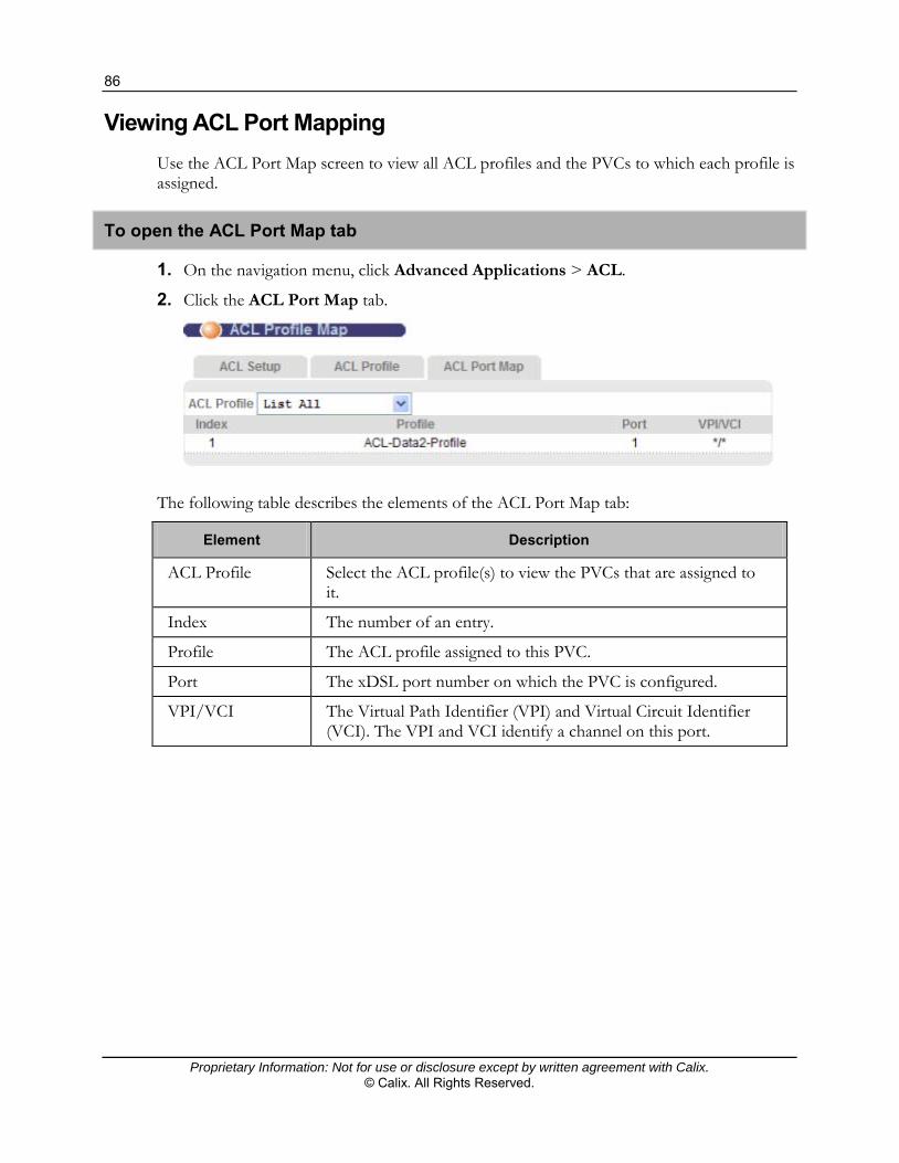
86
Proprietary Information: Not for use or disclosure except by written agreement with Calix. © Calix. All Rights Reserved.
Viewing ACL Port Mapping
Use the ACL Port Map screen to view all ACL profiles and the PVCs to which each profile is assigned.
To open the ACL Port Map tab
1. On the navigation menu, click Advanced Applications > ACL.
2. Click the ACL Port Map tab.
The following table describes the elements of the ACL Port Map tab:
Element Description
ACL Profile Select the ACL profile(s) to view the PVCs that are assigned to it.
Index The number of an entry.
Profile The ACL profile assigned to this PVC.
Port The xDSL port number on which the PVC is configured.
VPI/VCI The Virtual Path Identifier (VPI) and Virtual Circuit Identifier (VCI). The VPI and VCI identify a channel on this port.

87
Proprietary Information: Not for use or disclosure except by written agreement with Calix. © Calix. All Rights Reserved.
Creating VoIP Service Profiles
This section describes how to create profiles that are applied when you configure VoIP settings for E3-12C/E5-121 ports.
Related topic
Configuring VoIP Services (on page 183)
Creating SIP Profiles
This topic describes how to configure basic information about the SIP accounts used by the E3-12C/E5-121. The parameters should be set according to your particular VoIP switch setup.
To create a SIP profile
1. On the navigation menu, click VoIP > SIP Profile.
2. In the SIP Profile page, do the following:
Note: Clicking Cancel before clicking Add resets the parameter values to the previously-saved settings.
a. In the Name box, type a name for this SIP profile (up to 31 characters; spaces and dashes are not permitted).

88
Proprietary Information: Not for use or disclosure except by written agreement with Calix. © Calix. All Rights Reserved.
b. In the SIP IP / Domain Name box, type the IP address or domain name of your VoIP provider’s SIP server (up to 64 printable ASCII characters). It does not matter whether the SIP server is a proxy, redirect, or register server.
c. In the corresponding Port box, type the SIP server’s listening port number, if supplied by the VoIP service provider. Otherwise, keep the default value.
d. In the Registrar IP / Domain Name box, type the IP address or domain name of the SIP registrar server, if supplied by the VoIP service provider (up to 64 printable ASCII characters). Otherwise, enter the same address you entered in the SIP IP / Domain Name field.
e. In the corresponding Port box, type the SIP registrar server’s listening port number, if supplied by the VoIP service provider. Otherwise, enter the same port number you entered in the SIP IP / Domain Name Port field.
f. In the Proxy Server IP / Domain Name box, type the IP address or domain name of the SIP server or outbound proxy SIP server, if supplied by your VoIP service provider.
The E3-12C/E5-121 uses this address to communicate with the SIP server.
g. In the corresponding Port box, type the SIP outbound server’s listening port number, if supplied by the VoIP service provider. Otherwise, enter the same port number you entered in the SIP IP / Domain Name Port field.
h. In the URI Type list, configure how Universal Resource Indicators (URIs) are sent.
Select SIP where SIP messages are sent to a domain name or IP address.
Select TEL where SIP messages are sent to addresses represented as telephone numbers.
i. In the 802.1p Priority list, set the IEEE 802.1p priority value for traffic using this SIP profile (0 to 7).
j. In the DSCP box, set the DiffServ Code Point (DSCP) value for traffic using this SIP profile.
k. In the Keep Alive box, select whether the SIP Session Keep Alive is ON or OFF.
When this is ON, the SIP UA periodically sends SIP session refresh requests. Enter the minimum number of seconds after which the E3-12C/E5-121 tears down the session (if no successful session refresh has occurred).
l. In the Provisional Response ACK box, select whether the E3-12C/E5-121 sends provisional acknowledgment messages (ON), or does not send them (OFF).
m. In the Registration Expiration box, type the duration of the SIP registration request (60 to 3600 seconds).
3. Click Add or Apply to save your changes to the system volatile memory.
4. (Recommended) On the navigation menu, use the Config Save option to save changes to non-volatile memory.

89
Proprietary Information: Not for use or disclosure except by written agreement with Calix. © Calix. All Rights Reserved.
To modify a SIP profile
1. On the navigation menu, click VoIP > SIP Profile.
2. In the profile list at the top of the screen, under the Select column, select the radio button of the profile to edit.
3. Click Load.
4. Referring to Step 2 in the preceding procedure, make the changes to the profile.
5. At the bottom of the screen, click Modify.
To delete a SIP profile
1. On the navigation menu, click VoIP > SIP Profile.
2. In the profile list at the top of the screen, under the Select column, select the radio button of the profile to delete.
3. At the bottom of the screen, click Delete.
Creating a SIP Numbering Plan
Number plans are used by the E3-12C/E5-121 to identify specific types of phone numbers dialed by a subscriber, and to process the number before transmission by deleting, replacing, or adding digits according to the relevant rule. The rule can also automatically add the country code and national destination (region) code, or deny the number pattern entirely.
If a custom numbering plan is not applied to a VoIP ports, the E5 applies the default numbering plan table (DEFVAL) which contains a generic digit entry rule and a rule for 911 calling.
Digit collection timeout and calling
The default digit collection timeout (referred to as the inter digit timeout) is 10 seconds for defined numbering plan tables. If at any point during the 10-second timeout sufficient digits are collected, the call is made immediately.
Note: If you apply a custom numbering plan with no rule entries, a digit collection timeout of three seconds is enforced regardless how many digits are collected.
Example: Seven-digit local dialing numbering plan for North America
The following example numbering plan table contains 20 entries supporting seven-digit local dialing requirements (line 19), 1+10 digit long distance calling (entry 18), 011 international dialing (line 20), 911 and 411 calls (lines 1 and 2), and entries for Vertical Service Codes (VSC).

90
Proprietary Information: Not for use or disclosure except by written agreement with Calix. © Calix. All Rights Reserved.
Note: If local calling uses 10-digit dialing, the entry for line 19 should be "([2~9][0~9]{9})".
Note: The sample seven-digit North American dialing plan in the E3-12C/E5-121 Configurator Web interface cannot be edited. To modify it, you must create a new dialing plan.

91
Proprietary Information: Not for use or disclosure except by written agreement with Calix. © Calix. All Rights Reserved.
Creating and Modifying SIP Number Plans
This topic describes how to create and delete number plan tables for SIP VoIP service.
Note: To define a numbering plan, the E3-12C/E5-121 must be set to SIP VoIP mode.
Process overview
Define a numbering plan, as described below. Create a Call Service Profile using the defined numbering plan (VoIP > Call Service
Profile). Apply the Call Service Profile to VoIP ports (VoIP > VoIP Port Setup).
To create and define a SIP numbering plan
1. On the navigation menu, click VoIP > Number Plan Table.
2. In the Table Management tab, do the following:
a. In the Table Name box, type the name for the number plan table (up to 31 characters).
b. Click New.
c. In the number list table, under the Select column, select the radio button of the number plan you just created (or are editing).
d. Click Load.

92
Proprietary Information: Not for use or disclosure except by written agreement with Calix. © Calix. All Rights Reserved.
The selected number plan table opens in the Table Edit tab. At the top of the page, the name entered in the Table Management tab displays.
3. In the Default Rule box, type the default rule to use if different than "\1".
4. For each rule that you create, type the pattern string and rule string. For allowed characters, refer to the table below.
Note: When the E3-12C/E5-121 checks a dialed number against the table, it checks the patterns in numerical order from 1 to 32, so the ordering of the pattern string/rule string rules is important.
5. Click Apply.
The following table describes the options for creating entries for the Pattern String and Rule String fields for number plan table entries.

93
Proprietary Information: Not for use or disclosure except by written agreement with Calix. © Calix. All Rights Reserved.
Label Description
Pattern String The dialed number (up to 47 characters) to which the table entry applies. Allowed characters:
Numerals 0 to 9 * (asterisk) – wildcard match for variable number of digits x – any single digit in the range 0 to 9 T – pause timeout send of dial string, can only be last pattern in
the pattern string, see below for definitions S – star phone key (*) match character in dial plan P – pound key (#) match character in dial plan . (period) – zero or more repetitions of character or range that
precedes it; you cannot use this character inside brackets | (verical line) – rule separator for multiple number plan rules Range format characters: ~ (tilda) – must be connected with characters; can be included
within brackets , (comma) – can be included within brackets ( and ) (parentheses) – only one pair can be used for each rule [ and ] (brackets) – must pair and brackets cannot be nested;
"[n~m,k]" specifies to match a range of digits n to m or a specified digit k.
{ and } (braces) – {n} specifies to match n digits For example, if a Pattern String entry is “0021*”, the corresponding Rule String is applied to any dialed number starting from “00210” to “00219”.

94
Proprietary Information: Not for use or disclosure except by written agreement with Calix. © Calix. All Rights Reserved.
Label Description
Rule String The value with which the pattern string is to be replaced (up to 15 characters).
Permitted characters: Numerals 0 to 9 \c – country code \d – national destination or region code \1 – represents the matched string enclosed by the parentheses in
the pattern string. Note: If c\ or d\ is used in conjunction with \1, then \1 must be included as the last two characters in the rule string.
\n – no local disconnect—the call match pattern is not allowed local disconnection.
\p – partial pattern—after matching the partial pattern, no dialout string is sent out and the dialin string is used to match other pattern strings. The \p rule can provide some actions before the final pattern string is matched.
\t – tone—sends a confirmation tone back to the POTS port \tr – tone recall deny – the pattern string is not allowed
Timeout values (1 to 20 seconds) and definitions
Initial timeout (default = 20) – first digit must be dialed before the timeout. Inter-digit timeout (default = 10) – if no pattern string is fully matched, the inter-digit
timeout will trigger the E5 to send out current dialed digits. Pause timeout (default = 5) – if a pattern string is end with the T pattern, the pattern
string will not be matched until the timeout happens. Matching timeout (default = 3) – if a pattern string is fully matched, and there are other
pattern strings partially matched, the pattern string will be sent out if the timeout happens.
Fully matching – if a pattern string is fully matched, and no other pattern string is partially matched, the pattern string will be sent out immediately.
Matching to partial pattern – if \p is specified in a rule, the rule will be applied immediately after the corresponding pattern is fully matched regardless of whether there is another partially matched pattern.

95
Proprietary Information: Not for use or disclosure except by written agreement with Calix. © Calix. All Rights Reserved.
Examples
911 calling typically uses "(911)" in the pattern string and "\1\n" in the rule string. In the DEFVAL number plan table, an entry for 911 calling is included.
The following is an example of a four-digit number plan preceded by the number symbol (#): (P[2~9][0~9]{3})
If the pattern string is "002(*)", the rule string is "\c\1" and the country code in the relevant call service profile is "28", the dialed number "00244123456" becomes "28123456".
If the pattern string is "010(*)", the rule string is "\d\1" and the national destination code in the relevant call service profile is "01473", the dialed number "010456789" becomes "01473456789".
If the pattern string is "0440(1*)" and the rule string is "\1", the dialed number "04401473987654" becomes "473987654".
Creating Call Service Profiles
This topic describes how to configure information about the call service profiles used by the E3-12C/E5-121.
Configuration guidelines
Typically you use a unique Call Service Profile for each port on the system. The name and extension number must match the extension record for that user in the VoIP switch.
For SIP VoIP service, before creating a call service profile, determine the number plan table you are using. If it has not already been defined, create one.
For C7 TDM Gateway VoIP service, the only call service profile option available in Step 2 in the following procedure is the SIP password. If a SIP password is not required in this mode, the DEFVAL call service profile can be used when configuring service on the VoIP port.
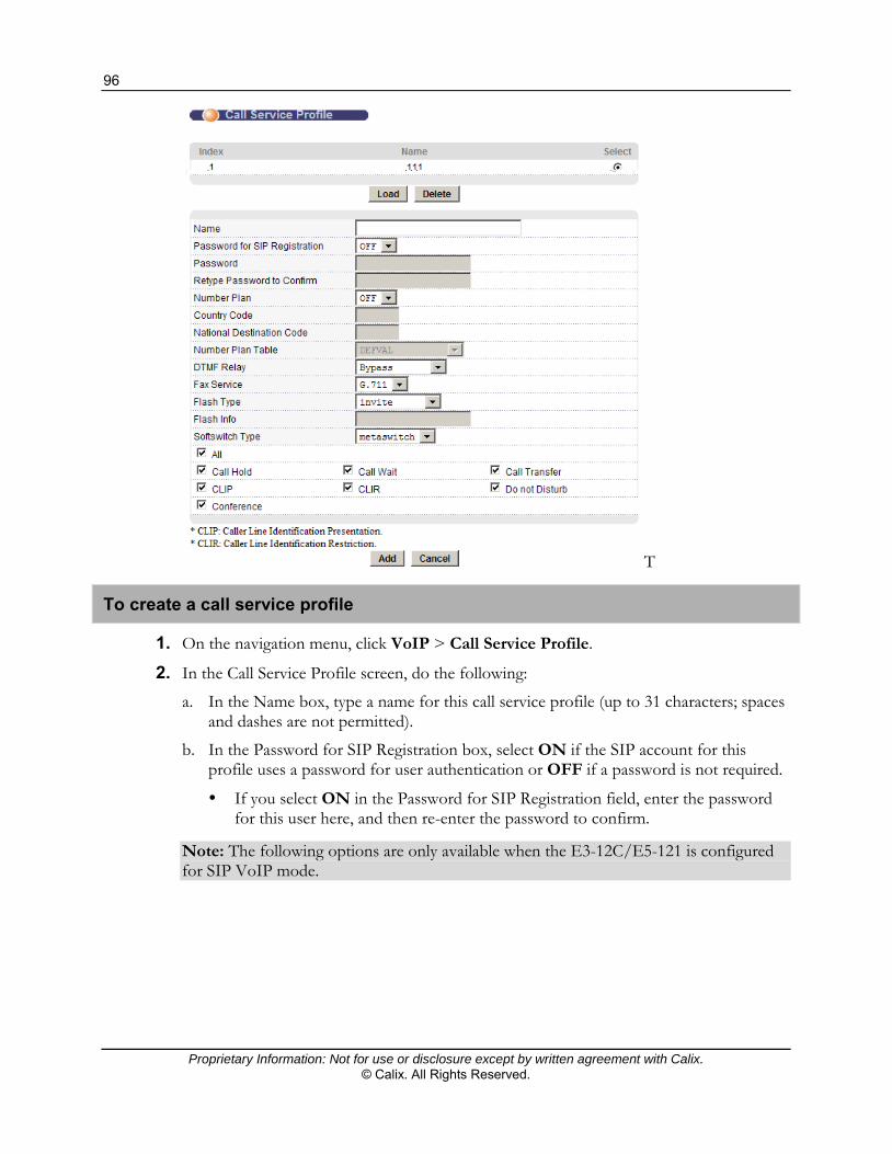
96
Proprietary Information: Not for use or disclosure except by written agreement with Calix. © Calix. All Rights Reserved.
T
To create a call service profile
1. On the navigation menu, click VoIP > Call Service Profile.
2. In the Call Service Profile screen, do the following:
a. In the Name box, type a name for this call service profile (up to 31 characters; spaces and dashes are not permitted).
b. In the Password for SIP Registration box, select ON if the SIP account for this profile uses a password for user authentication or OFF if a password is not required.
If you select ON in the Password for SIP Registration field, enter the password for this user here, and then re-enter the password to confirm.
Note: The following options are only available when the E3-12C/E5-121 is configured for SIP VoIP mode.

97
Proprietary Information: Not for use or disclosure except by written agreement with Calix. © Calix. All Rights Reserved.
c. In the Number Plan list, select ON use the number plan table specified in the Number Plan Table field OFF to use the DEFVAL number plan table. If you select ON, complete the following:
In the Country Code box, type the numeric code for the country of operation. This value is used by the number plan table’s “\c” function.
In the National Destination Code box, type the numeric code for the region of operation. This value is used by the number plan table’s “\d” function.
In the Number Plan Table list, select the number plan to use for this call service profile.
d. In the DTMF Relay list:
Select Bypass to not relay DTMF (Dual-Tone Multi-Frequency) tones.
Select RFC2833 to relay DTMF tones according to RFC 2833.
Select RFC2833 Like to relay DTMF tones in SIP INFO packets, but carried as RFC 2833 payload.
Select SIP Info to relay DTMF tones as SIP INFO messages.
e. In the Fax Service list:
Select T.38 to send fax signals according to ITU-T T-38.
Select G.711 to send fax signals according to ITU-T G.711.
f. In the Flash Type list, specify how to handle the hook flash event:
invite - by the E3-12C/E5-121. A re-invite is sent out to control the call services.
bypass - stand by following the softswtich type setting.
rfc2833 - E3-12C/E5-121 reports a RFC 2833 hook flash event to the softswitch.
rfc2833like - E3-12C/E5-121 reports a RFC 2833 hook flash event in SIP INFO packets, but carried as a RFC 2833 payload.
sipinfo-1 - by SIP INFO signal=16 message.
sipinfo-2 - by SIP INFO signal=hf message.
sipinfo-3 - by SIP INFO signal=hook-flash message.
sipinfo-4 - by SIP INFO plain text FLASH message.
sipinfo-5 - by multiple SIP INFO signal messages and content of signal messages coming from the specified replace characters. With this option, include up to 7 replaced characters in the Flash Info box.
sipinfo-6 - by specified SIP INFO message. With this option, include the message (up to 31 characters) in the Flash Info box.
If you select sipinfo-5 or sipinfo-6 in the Flash Info list, enter the replacement characters or SIP information message, respectively.

98
Proprietary Information: Not for use or disclosure except by written agreement with Calix. © Calix. All Rights Reserved.
g. (E3-12C and E5-121 only) In the CPC list, select ON to enable the "call held after on-hook" feature, and then type timeout period (5 to 60 seconds) in the box to the right of the list.
When enabled, if the called party goes on-hook and the calling party remains off-hook, the call is held for the specified length time before disconnecting.
h. In the Softswitch Type list, select the softswitch type used: Metaswitch or Genband.
Note: Use Metaswitch for PGi and Taqua softswitches.
Select the All check box to enable all the call features listed, or select individual check boxes to enable specific features:
♦ Call Hold ♦ Call Wait ♦ Call Transfer ♦ CLIP (Caller Line Identification Presentation) ♦ CLIR (Caller Line Identification Restriction) ♦ Do Not Disturb ♦ Conference
3. Click Add or Apply to save your changes to the system volatile memory.
4. (Recommended) On the navigation menu, use the Config Save option to save changes to non-volatile memory.
The profile name and corresponding index number display in the profile list.
To edit or delete a Call Service profile
1. On the navigation menu, click VoIP > Call Service Profile.
2. Do one of the following:
To modify a profile, under the Select column in the profile list at the top of the page, select the profile to edit, and then click Load. After making changes to the profile parameters, at the bottom of the page, click Modify.
To delete a profile, under the Select column in the profile list at the top of the page, select the profile to deleted, and then below the profile list, click Delete.
On the navigation menu, use the Config Save option to save changes to non-volatile memory.
Related topic
Creating a SIP Numbering Plan (on page 89)

99
Proprietary Information: Not for use or disclosure except by written agreement with Calix. © Calix. All Rights Reserved.
Configuring DSP Profiles
This topic describes how to configure information about the Digital Signal Processing (DSP) profiles used by the E3-12C/E5-121.
To create a DSP profile
1. On the navigation menu, click VoIP > DSP Profile.
a. In the Name box, type a name for this DSP profile (up to 31 characters in length; spaces and dashes are not permitted).
b. In the Codec section, select the voice coder/decoders you are allowing or not allowing for this DSP profile:
Note: For C7 TDM Gateway VoIP mode, the E3-12C/E5-121 only supports G.711µ.
Allowed—the list of codecs the E3-12C/E5-121 can use for negotiation. Codecs are listed by priority: the E3-12C/E5-121 attempts to use the codec at the top of the list first and, if that is not possible, it tries the second, and so on.
Not Allowed—the list of codecs not to use in this DSP profile.
<- button moves the selected codec from the Not Allowed list to the Allowed list.

100
Proprietary Information: Not for use or disclosure except by written agreement with Calix. © Calix. All Rights Reserved.
-> button moves the selected codec from the Allowed list to the Not Allowed list.
Priority + button increases the priority of the selected codec by moving it up one place in the list.
Priority - button decreases the priority of the selected codec by moving it down one place in the list.
c. In the Min Play Buffer Delay box, type the minimum time delay of the play buffer (10 to 500 milliseconds, must be less than or equal to the Max Play Buffer Delay). Default: 30 ms
d. In the Max Play Buffer Delay box, type the maximum time delay of the play buffer (10 to 500 milliseconds, must be greater than or equal to the Min Play Buffer Delay). Default: 120 ms
e. In the Echo Tail list, select the echo-cancellation echo tail period (8/16/32/128 milliseconds).
f. In the VoIP Codecs lists, select the rate for the individual VoIP codecs.
2. Click Add or Apply to save your changes to the system volatile memory.
3. (Recommended) On the navigation menu, use the Config Save option to save changes to non-volatile memory.
The profile name and corresponding index number display in the profile list.
To edit or delete a DSP profile
1. On the navigation menu, click VoIP > DSP Profile.
2. Do one of the following:
To modify a profile, under the Select column in the profile list at the top of the page, select the profile to edit, and then click Load. After making changes to the profile parameters, at the bottom of the page, click Modify.
To delete a profile, under the Select column in the profile list at the top of the page, select the profile to deleted, and then below the profile list, click Delete.
3. On the navigation menu, use the Config Save option to save changes to non-volatile memory.

101
Proprietary Information: Not for use or disclosure except by written agreement with Calix. © Calix. All Rights Reserved.
Configuring H.248 Profiles
Use the VoIP H.248 Profile screen to create profiles for H.248 VoIP service.
To open the H.248 Profile screen
1. On the navigation menu, click VoIP > H.248 Profile.
a. In the Name box, type a name for this H.248 profile (up to 31 characters in length;
spaces and dashes are not permitted).
b. In the MGC IP / Domain Name box, type the media gateway controller IP address or domain name (up to 63 characters).

102
Proprietary Information: Not for use or disclosure except by written agreement with Calix. © Calix. All Rights Reserved.
c. In the Port box, type the media gateway controller port number (1025 to 65535) to use. The default is 2944.
d. (Optional) In the MGC2 list, select ON to configure a secondary media gateway controller for the profile, and then type the media gateway controller IP address or domain name and media gateway controller port number to use. If applicable, type the IP/Domain name and port number to use in the appropriate fields.
e. In the Transport list, select the transport protocol: UDP or TCP.
f. In the Encoding list, select the encoding for H.248 messages: LONG or SHORT.
g. In the 802.1p Priority list, select the 802.1p priority bit for H.248 packets (0 to 7).
h. In the DSCP box, type the DiffServ Code Points (DSCP) for H.248 packets (0 to 63).
i. In the Ephemeral Termination Prefix, Start Number and Suffix Length lists, type the ephemeral termination prefix, suffix start number (up to 15 digits), and suffix number length (0 to 15, with padding zero in front if not long enough; 0 disables padding).
j. In the Physical Termination Prefix, Start Number and Suffix Length lists, type the physical termination prefix, suffix start number (up to 15 digits), and suffix number length (0 to 15, with padding zero in front if not long enough; 0 disables padding).
k. In the Softswitch list, select the softswitch (DEFVAL is used until a supported switch type is selected):
metaswitch (for Metaswitch, PGi, and Taqua)
genband-cs1500 (for Genband CS1500/C15)
genband-cs2000 (for Genband CS2000/C20)
l. The VBD list, select ON to enable or Off to disable Voice Band Data (VBD) mode support.
m. In the Force Version list, select ON to enable or OFF to disable forced use of H.248.
n. In the Realtime Transport Protocol (RTP) Port Range boxes, type the start (even, from 4000 to 64000) and end numbers (even, from 5000 to 65000). Note: The end number must be at least 1000 higher than the start number.
2. Click Add or Apply to save the settings to volatile memory.
3. Calix recommends periodically saving configuration changes to non-volatile memory using the Config Save option on the navigation menu.

103
Proprietary Information: Not for use or disclosure except by written agreement with Calix. © Calix. All Rights Reserved.
To edit or delete an H.248 profile
1. On the navigation menu, click VoIP > H.248 Profile.
2. Do one of the following:
To modify a profile, under the Select column in the profile list at the top of the page, select the profile to edit, and then click Load. After making changes to the profile parameters, at the bottom of the page, click Modify.
To delete a profile, under the Select column in the profile list at the top of the page, select the profile to deleted, and then below the profile list, click Delete.
On the navigation menu, use the Config Save option to save changes to non-volatile memory.

104
Proprietary Information: Not for use or disclosure except by written agreement with Calix. © Calix. All Rights Reserved.

Proprietary Information: Not for use or disclosure except by written agreement with Calix. © Calix. All Rights Reserved.
Chapter 5
Configuring Data Services
This section describes how to turn up E3-12C/E5-120/E5-121 xDSL data (Internet) services from the embedded web interface.
Tasks Covered
This chapter covers the following:
An overview of the E3-12C/E5-120/E5-121 data services configuration process Configuring VLAN per Service Data Model (N:1) Configuring VLAN per Port Data Model (1:1) Configuring TLS (Business Services)
Related topics
If you are provisioning data and video services, see the section, Configuring Video Services (on page 137).

106
Proprietary Information: Not for use or disclosure except by written agreement with Calix. © Calix. All Rights Reserved.
Data Services Overview: Supported Service Models
The E3-12C/E5-120/E5-121 supports these data service models:
VLAN-per-Service: where each service is assigned a dedicated VLAN where multiple subscriber ports are assigned to the VLAN for a single service. This model is often referred to as N:1.
VLAN-per-Port: where each subscriber port is assigned a dedicated VLAN. This model is often referred to as 1:1.
VLAN Stacking, Q-in-Q: where a transparent LAN service on each port is configured using VLAN double tagging.
For more information, see the Calix E3-12C/E5-100 Engineering and Planning Guide.

107
Proprietary Information: Not for use or disclosure except by written agreement with Calix. © Calix. All Rights Reserved.
Configuring VLAN-per-Service Data Model (N:1)
This section describes how to turn-up an E3-12C/E5-120/E5-121 for a data (Internet) service, using the VLAN-per-service model (N:1 VLAN model) where VLAN tags are assigned to services.
Data Provisioning Checklist: VLAN-per-Service Model
Starting point
Before starting the configuration process, check that the conditions in the following table are met.
Description Reference
Verify that the Ethernet uplink is installed and configured, SFP modules are installed, and fibers are connected.
Verify that the correct switch priority queue is applied to the VLANs. Note: Typically, switch priority queue settings do not need to be modified.
Configuring the Ethernet Links (on page 49)
Setting Up the Switch (on page 59)
Verify that the DSL subscriber interfaces are wired.
Gather xDSL port setting requirements to create custom xDSL port profiles.
Gather subscriber template attributes. For ports using ADSL mode, have on hand the VPI/VCI values used by the subscriber CPE.
Have on hand the VLAN ID(s) to use for data and video services.
Configure bonding groups, if required. Configuring Bonding Groups (on page 216)
Turn-up process
The service turn-up process includes the steps in the following table.
Description Reference
Create a data VLAN and assign membership. Configuring the Service VLAN and Assigning VLAN Membership (on page 108)
Create xDSL port profiles to define port operation settings. Creating xDSL Profiles (ADSL/VDSL) (on page 67)
Sample xDSL Profiles (on page 71)
Configure xDSL port settings and copy port settings to multiple ports. Configuring xDSL Port Settings: VLAN-per-Service Data Model (on page 110)

108
Proprietary Information: Not for use or disclosure except by written agreement with Calix. © Calix. All Rights Reserved.
Next steps
The following tasks can be performed based on per-site or per-subscriber port requirements:
Configure DHCP settings for the data VLAN. See DHCP Relay (on page 218). For subscriber CPEs operating in ADSL mode, configure VC parameters for the xDSL
port. See Apply VC Parameters to xDSL Ports (on page 238). Configure MAC forced-forwarding (MACFF) rules. See Configuring MACFF Settings (on
page 248). Note: MACFF cannot be used with Point-to-Point over Ethernet (PPPoE), VLAN stacking (double tagging, or Q-in-Q), or transparent LAN service (TLS) traffic on the same port/VLAN ID.
For information about DSCP priority bit activation and mapping, see DSCP (on page 242).
When multiple data service VLANs are mapped to a port:
Create IP QoS profiles to classify and prioritize data traffic for each data service plan. See Creating IP QoS Profiles (on page 74).
Create ACL profiles to classify and perform actions on the upstream data traffic and apply them to ports. See Creating ACL Profiles (on page 80) and Applying ACL Profiles to a Set of xDSL Ports (on page 83).
To define port operation settings, you can configure attributes for data services such as customized SNR settings (on page 237), PPPoA-to-PPPoE conversions (on page 225), and DHCP snooping (on page 256).
To define xDSL port alarm thresholds, create xDSL alarm profiles and apply them to ports. See Creating xDSL Alarm Profiles (on page 77).
Configuring the Service VLAN and Assigning Membership
For a checklist of provisioning steps, see the Data Provisioning Checklist: VLAN-per-Service Model (on page 107).
This topic describes how to create a VLAN for data service. On a system using the VLAN-per-service model, you only need to create one VLAN for data.
To configure the data service VLAN and assign VLAN membership
1. In the Navigation menu, click Advanced Applications > VLAN.
2. Click the Static VLAN Settings tab, and then do the following:
a. Make sure the Active checkbox is selected.
b. In the Name box, type a descriptive name for this VLAN group for identification purposes.
Note: Spaces are not allowed in the name.

109
Proprietary Information: Not for use or disclosure except by written agreement with Calix. © Calix. All Rights Reserved.
c. Type the VLAN ID for this static VLAN entry; the valid range is between 1 and 4094.
d. In the Control column, select ENET and xDSL ports as Fixed for the ports to be permanent members of this VLAN. Use the Select All button to include every port.
e. In the Tagging column, set the tagging parameters appropriately. For a typical data-only configuration, do the following:
For ENET1 and ENET2 ports, select the Tx Tagging check box (tagged).
For xDSL ports, leave the Tx Tagging check box clear (untagged).
Note: For VDSL services, traffic can be tagged or untagged on the xDSL port, and this setting must match the configuration of the VDSL modem. Finally, if you are provisioning both data and video services over VDSL, you have two options: 1) set the xDSL port tagged for one service and leave the other untagged; or 2) set both services to tagged. In a typical ADSL data service configuration, traffic is tagged from the IP DSLAM to the upstream switch (Ethernet ports ENET1 and ENET2), and not tagged from the IP DSLAM toward the xDSL subscribers (xDSL ports).
f. Click Add.
3. (For VDSL ports only) Click the VLAN Port Settings tab, and then do the following:
a. In the PVID box for the port identified, type the Port VLAN ID (PVID) to assign to untagged, upstream traffic or priority frames (0 VID).
b. In the Priority list for the port identified, select an IEEE 802.1p priority to assign to untagged frames or priority frames (0 VID) received on this port.
c. At the bottom of the screen, click Apply to save the settings to E3-12C/E5-120/E5-121 volatile memory. Calix recommends periodically saving configuration changes to non-volatile memory using the Config Save option on the navigation menu.
Related topics
Viewing VLAN Statuses (on page 284) Editing and Deleting Static VLANs (on page 286)

110
Proprietary Information: Not for use or disclosure except by written agreement with Calix. © Calix. All Rights Reserved.
Configuring xDSL Port Settings: VLAN-per-Service Data Model
For a checklist of provisioning steps, see the Data Provisioning Checklist: VLAN-per-Service Model (on page 107).
This topic describes how to configure general xDSL port settings and apply any previously-created xDSL, xDSL alarm, and IP QoS profiles.
To configure the xDSL port settings
1. On the navigation menu, click Basic Settings > xDSL Port Setup.
2. On the xDSL Port Setup tab, do the following:
a. Under the Port column, click the link to the port you are configuring.
b. Select the Active check box to enable the port.
c. In the Customer Info box, type information to identify the subscriber connected to the ADSL port (up to 31 characters; spaces and hyphens are allowed).
d. In the Customer Tel box, type information to identify the telephone number of the subscriber connected to the port (up to 15 characters; spaces and hyphens are allowed).

111
Proprietary Information: Not for use or disclosure except by written agreement with Calix. © Calix. All Rights Reserved.
e. In the Profile list, select a profile of xDSL settings (transfer rates, latency mode and interleave delay, and signal-to-noise ratio settings) to assign to the port.
f. In the Mode area of the screen, select the port’s operational mode based on subscriber’s CPE:
Note: By default, auto is selected for the E3-12C/E5-120/E5-121 to automatically determine the mode to use.
To select VDSL2 with a specific ADSL fallback mode, click one of the VDSL2 + fall back options in the first column, under Auto.
To select a VDSL2-only profile (8a, 8b, 8c, 8d, 12a, 12b, 17a), in the second column of options, select the profile, or select VDSL2 for the E3-12C/E5-120/E5-121 to automatically determine the VDSL2 profile to use.
To select an ADSL standard, click one of the service types in the third column of options.
g. If you have created an alarm profile to use, in the Alarm Profile list, select the profile to define alarm thresholds for the xDSL port. The E3-12C/E5-120/E5-121 sends an alarm trap and generates a syslog entry when the thresholds of the alarm profile are exceeded.
h. In the IGMP Profile list, leave the default profile selected unless you are also provisioning video service.
i. In the IP QoS Profile list, leave the DEFVAL profile selected unless you are also provisioning video service or more than one data service.
3. In the Advanced Features area you can customize the following xDSL port settings:
Note: Not all CPE chipsets support the advanced features on the xDSL Port Settings screen. For interoperability questions, refer to the E3-12C/E5-120/E5-121 Release Notes or check with Calix Technical Assistance Center (TAC).
a. In the Option Mark area, select one or more option masks (clicking the ALL check box selects all option mask selections):
Disable one or more of these settings: Trellis, Reed-Solomon, Upstream Bitswap, Downstream Bitswap, 1-bit Constellation, Transmit Windowing, s=0.5 Support (ADSL1 only).
Enable one or more of these settings: Nitro, ADSL2 Annex L, ADSL2+ Annex M, upstream point-to-multipoint (US PTM) optimization, downstream PTM optimization, upstream PhyR, and downstream PhyR.
b. Enable, disable, or select these settings: RFI Band, Limit Mask, Seamless Rate Adaptation (SRA), minimum impulse noise protection (Min INP), and the upstream and downstream power-back-off (UPBO and DPBO).
c. In the RFI Custom area, use the Enable check box and the Start and End boxes to activate customized RFI band start and end frequencies.

112
Proprietary Information: Not for use or disclosure except by written agreement with Calix. © Calix. All Rights Reserved.
4. At the bottom of the screen, click Apply to save your changes to the system volatile memory.
5. To navigate back to the xDSL Setup screen, at the top right of the screen, click the Up hyperlink.
(Recommended) On the navigation menu, use the Config Save option to save changes to non-volatile memory.
Related topics
Creating xDSL Profiles (on page 67) Creating xDSL Alarm Profiles (on page 77) Creating IP QoS Profiles (on page 74) Copying xDSL Port Settings (on page 232) Advanced xDSL Port Settings (on page 234)

113
Proprietary Information: Not for use or disclosure except by written agreement with Calix. © Calix. All Rights Reserved.
Configuring VLAN-per-Port Data Model (1:1)
This section describes how to turn-up an E3-12C/E5-120/E5-121 for a data (Internet) service, using the VLAN-per-port data model (1:1 VLAN model).
1:1 VLAN-per-Port, Single Tagged – Subscribers on an E3-12C/E5-120/E5-121 system are provisioned with individual Customer Tags (C-Tags).
1:1 VLAN-per-Port, Double Tagged – Subscribers on an E3-12C/E5-120/E5-121 system are provisioned with individual Customer Tags (C-Tags). The S-Tag can be added by the upstream device.
The 1:1 model does not require any new or different traffic handling techniques to isolate and manage subscriber traffic. With the 1:1 service delivery model, each subscriber's traffic (except broadcast video) is sent down a dedicated single VLAN on a per subscriber basis. When ATM framing is used for ADSL/ADSL2+ modes, the single ATM PVC maps to a single VLAN.
Data Provisioning Checklist: VLAN-per-Port Data Model
Starting point
Before starting the configuration process, check that the conditions in the following table are met.
Description Reference
Verify that the Ethernet uplink is installed and configured, SFP modules are installed, and fibers are connected.
Verify that the correct switch priority queue is applied to the VLANs. Note: Typically, switch priority queue settings do not need to be modified.
Configuring the Ethernet Links (on page 49)
Setting Up the Switch (on page 59)
Verify that the DSL subscriber interfaces are wired.
Gather xDSL port setting requirements to create custom xDSL port profiles.
Gather subscriber template attributes. For ports using ADSL mode, have on hand the VPI/VCI values used by the subscriber CPE.
Have on hand the VLAN ID(s) to use for data and video services.
Configure bonding groups, if required. Configuring Bonding Groups (on page 216)

114
Proprietary Information: Not for use or disclosure except by written agreement with Calix. © Calix. All Rights Reserved.
Turn-up process
The service turn-up process includes the steps in the following table.
Description Reference
Create a data VLAN for each subscriber you are provisioning and assign membership.
If you are provisioning double-tagged services, create a static VLAN for each S-tag.
Configuring the Service VLAN and Assigning VLAN Membership (on page 115)
Create xDSL port profiles to define port operation settings and apply them to ports.
Creating xDSL Profiles (ADSL/VDSL) (on page 67)
Sample xDSL Profiles (on page 71)
Configure xDSL port settings. Configuring xDSL Port Settings: VLAN-per-Port Data Model (on page 116)
(For double-tagging applications) Configure double-tagging or a double-tagged permanent virtual circuit (DT PVC).
Configuring Double-Tagging for a VDSL Port (on page 119)
Configuring Double-Tagging for an ADSL Port (on page 121)
(For subscriber CPEs operating in ADSL mode) Configure VC parameters for the xDSL port.
Apply VC Parameters to xDSL Ports (on page 238)
Next steps
The following tasks can be performed based on per-site or per-subscriber port requirements:
To define port operation settings, configure attributes for data services such as customized SNR settings (on page 237), PPPoA-to-PPPoE conversions (on page 225), DHCP relay (on page 218), and DHCP snooping (on page 256).
Configure MAC forced-forwarding (MACFF) rules (not applicable for double-tagged applications or ports configured for PPPoE). See Configuring MACFF Settings (on page 248).
For information about DSCP priority bit activation and mapping, see DSCP (on page 242).
When multiple data service VLANs are mapped to a port:
Create IP QoS profiles to classify and prioritize data traffic for each data service plan. See Creating IP QoS Profiles (on page 74).
Create ACL profiles to classify and perform actions on the upstream data traffic and apply them to ports. See Creating ACL Profiles (on page 80) and Applying ACL Profiles to a Set of xDSL Ports (on page 83).
To define alarm thresholds, create xDSL alarm profiles and apply them to ports. See Creating xDSL Alarm Profiles (on page 77).

115
Proprietary Information: Not for use or disclosure except by written agreement with Calix. © Calix. All Rights Reserved.
Configuring the Service VLAN and Assigning Membership
For a checklist of provisioning steps, see the Data Provisioning Checklist: VLAN-per-Port Model (on page 113).
This topic describes how to create a VLAN for data services. On a system using the VLAN-per-port model, create one VLAN for each subscriber you are provisioning. If you are provisioning double-tagged services, create a static VLAN for each S-tag.
To configure the data service VLAN and assign VLAN membership
1. In the Navigation menu, click Advanced Applications > VLAN.
2. Click the Static VLAN Settings tab, and then do the following:
a. Make sure the Active checkbox is selected.
b. In the Name box, type a descriptive name for this VLAN group for identification purposes.
Note: Spaces are not allowed in the name.
c. Type the VLAN ID for this static VLAN entry; the valid range is between 1 and 4094.
d. In the Control column, select ENET and xDSL ports as Fixed for the ports to be permanent members of this VLAN.
e. In the Tagging column, set the tagging parameters appropriately. For a typical data-only configuration, do the following:
For ENET1 and ENET2 ports, select the Tx Tagging check box (tagged).
For xDSL ports, leave the Tx Tagging check box clear (untagged) or select it (tagged), per subscriber requirements. Note the following: ♦ For VDSL services, traffic can be tagged or untagged on the xDSL port, and
this setting must match the configuration of the VDSL modem. ♦ In a typical ADSL data service configuration, traffic is tagged from the IP
DSLAM to the upstream switch (Ethernet ports ENET1 and ENET2), and not tagged from the IP DSLAM toward the xDSL subscribers (xDSL ports).
f. Click Add.
3. (For VDSL ports only) Click the VLAN Port Settings tab, and then do the following:
a. In the PVID box for the port identified, type the Port VLAN ID (PVID) to assign to untagged, upstream traffic or priority frames (0 VID).
b. In the Priority list for the port identified, select an IEEE 802.1p priority to assign to untagged frames or priority frames (0 VID) received on this port.
c. At the bottom of the screen, click Apply to save the settings to E3-12C/E5-120/E5-121 volatile memory. Calix recommends periodically saving configuration changes to non-volatile memory using the Config Save option on the navigation menu.

116
Proprietary Information: Not for use or disclosure except by written agreement with Calix. © Calix. All Rights Reserved.
Additional reference topics
Viewing VLAN Statuses (on page 284) Editing and Deleting Static VLANs (on page 286)
Configuring xDSL Port Settings: VLAN-per-Port Model
For a checklist of provisioning steps, see the Data Provisioning Checklist: VLAN-per-Port Model (on page 113).
This topic describes how to configure xDSL port settings and apply the following previously created service and traffic management profiles:
xDSL profile—see Creating xDSL Profiles (on page 67) and Sample xDSL Profiles (on page 71)
xDSL alarm profile—see Creating xDSL Alarm Profiles (on page 77) IP QoS Profile (if required)—see Creating IP QoS Profiles (on page 74)
See also:
For instructions on how to copy xDSL port settings to one or more ports, see Copying xDSL Port Settings (on page 232).

117
Proprietary Information: Not for use or disclosure except by written agreement with Calix. © Calix. All Rights Reserved.
To configure the xDSL port settings
1. On the navigation menu, click Basic Settings > xDSL Port Setup.
2. On the xDSL Port Setup tab, do the following:
a. Under the Port column, click the link to the port you are configuring.
b. Select the Active check box to enable the port.
c. In the Customer Info box, type information to identify the subscriber connected to the ADSL port (up to 31 characters; spaces and hyphens are allowed).
d. In the Customer Tel box, type information to identify the telephone number of the subscriber connected to the port (up to 15 characters; spaces and hyphens are allowed).
e. In the Profile list, select a profile of xDSL settings (transfer rates, latency mode and interleave delay, and signal-to-noise ratio settings) to assign to the port.
f. In the Mode area of the screen, select the port’s operational mode based on subscriber’s CPE:
Note: By default, auto is selected for the E3-12C/E5-120/E5-121 to automatically determine the mode to use.
To select VDSL2 with a specific ADSL fallback mode, click one of the VDSL2 + fall back options in the first column, under Auto.
To select a VDSL2-only profile (8a, 8b, 8c, 8d, 12a, 12b, 17a), in the second column of options, select the profile, or select VDSL2 for the E3-12C/E5-120/E5-121 to automatically determine the VDSL2 profile to use.
To select an ADSL standard, click one of the service types in the third column of options.
g. If you have created an alarm profile to use, in the Alarm Profile list, select the profile to define alarm thresholds for the xDSL port. The E3-12C/E5-120/E5-121 sends an alarm trap and generates a syslog entry when the thresholds of the alarm profile are exceeded.
h. In the IGMP Profile list, leave the default profile selected unless you are also provisioning video service.
i. In the IP QoS Profile list, leave the DEFVAL profile selected unless you are also provisioning video service or more than one data service.

118
Proprietary Information: Not for use or disclosure except by written agreement with Calix. © Calix. All Rights Reserved.
3. In the Advanced Features area you can customize the following xDSL port settings:
Note: Not all CPE chipsets support the advanced features on the xDSL Port Settings screen. For interoperability questions, refer to the E3-12C/E5-120/E5-121 Release Notes or check with Calix Technical Assistance Center (TAC).
a. In the Option Mark area, select one or more option masks (clicking the ALL check box selects all option mask selections):
Disable one or more of these settings: Trellis, Reed-Solomon, Upstream Bitswap, Downstream Bitswap, 1-bit Constellation, Transmit Windowing, s=0.5 Support (ADSL1 only).
Enable one or more of these settings: Nitro, ADSL2 Annex L, ADSL2+ Annex M, upstream point-to-multipoint (US PTM) optimization, downstream PTM optimization, upstream PhyR, and downstream PhyR.
b. Enable, disable, or select these settings: RFI Band, Limit Mask, Seamless Rate Adaptation (SRA), minimum impulse noise protection (Min INP), and the upstream and downstream power-back-off (UPBO and DPBO).
c. In the RFI Custom area, use the Enable check box and the Start and End boxes to activate customized RFI band start and end frequencies.
4. At the bottom of the screen, click Apply to save your changes to the system volatile memory.
5. To navigate back to the xDSL Setup screen, at the top right of the screen, click the Up hyperlink.
6. (Recommended) On the navigation menu, use the Config Save option to save changes to non-volatile memory.
Double-Tag (DT)
With double tagging enabled, the E3-12C/E5-120/E5-121 maps the VLAN ID and the priority levels of packets received from a private network (C-tag) to those used in the service provider’s network (S-tag), or adds a VLAN ID and priority level to untagged packets.
When you enable DT on a port, the port is called a DT access port. The E3-12C/E5-120/E5-121 adds VLAN tags for untagged traffic but drops tagged traffic flowing through DT access ports. Note that double-tagged or single-tagged packets received on the DT access ports are dropped.
When you configure a static VLAN group, PVID, protocol-based VLAN, or VLAN stacking on the E3-12C/E5-120/E5-121, the system automatically creates a corresponding DT rule for the related xDSL ports.
Use the DT tab to view the existing DT entries for xDSL ports. Calix recommends adding a new DT entry only to translate untagged packets into double-tagged packets before forwarding them. You can configure up to 16 DT rules for each port.

119
Proprietary Information: Not for use or disclosure except by written agreement with Calix. © Calix. All Rights Reserved.
The E3-12C/E5-120/E5-121 checks incoming traffic from the subscriber (xDSL) ports against the VLAN Translation Table (VTT), the MAC learning table, and the VLAN table before forwarding them through the Gigabit uplink port. If the incoming packets from the access ports are untagged, the E3-12C/E5-120/E5-121 adds or replaces the VLAN tag according to the double-tag (DT) rule. The E3-12C/E5-120/E5-121 discards packets that do not match an entry in the DT and VLAN table.
Note: To edit an automatically-generated VLAN Translation Table (VTT) entry, configure the rule in the corresponding VLAN screens.
Configuring Double Tagging for a VDSL Port
For a checklist of provisioning steps, see the Data Provisioning Checklist: VLAN-per-Port Model (on page 113).
This topic describes how to configure double tagging (DT) for a VDSL port.
You can use Double Tagging (DT) with VDSL service for different services or subscribers. Up to eight channels can be defined on each xDSL port for different services or levels of service and a priority assigned to each channel.
The purpose of double tagging is to receive untagged traffic from the subscriber and add a stacked double tag to it before sending the traffic to the uplink. In this stacked double-tag structure, the outer tag is the Service VLAN ID (S-VID) and the inner tag from the subscriber is the Customer VLAN ID (C-VID).
Configuration guidelines
A static VLAN (Advanced Applications > VLAN) entry must be created for the S-VID to include the intended DT port and the uplink Ethernet port. Note that you do not need to create a VLAN entry for the C-VID on the E3-12C/E5-120/E5-121.
When configuring a subscriber port for double-tagging, the CPE modem must be configured as untagged.
MAC Forced-Forwarding (MACFF) must be disabled on the port/VLAN. ACL profiles are not supported on ports with double tagging enabled. Any combination of DT S-VID and C-VID must be unique in the system. Only one DT VID can be configured.

120
Proprietary Information: Not for use or disclosure except by written agreement with Calix. © Calix. All Rights Reserved.
To configure DT for VDSL mode
1. On the navigation menu, click Advanced Applications > DT.
2. In the DT tab, and then do the following:
Note: Clicking Cancel resets the parameters at the top of the screen.
a. In the port list, select an xDSL port for the double-tagging entry that you are creating or editing.
b. In the S-tag VID box, type the service VLAN ID (S-VID) from 1 to 4094. The S-tag is the outer tag into which the Customer VLAN ID (C-VID) will be translated.
c. In the S-tag Priority list, select the service priority (S-Pri) from 0 to 7 into which the Customer Priority (C-Pri) will be translated.
d. In the C-tag VID box, type the Customer VLAN ID (C-VID) or leave the field blank for untagged incoming packets. The C-tag is the VLAN tag carried in the packets and will be translated into a service VLAN ID (S-VID).
e. In the C-tag Priority list, select the Customer Priority (C-Pri) from 0 to 7, or leave this field blank for untagged incoming packets. The C-tag priority is the VLAN tag carried in the packets and will be translated into an S-tag priority.
f. Select the DT Enable check box.

121
Proprietary Information: Not for use or disclosure except by written agreement with Calix. © Calix. All Rights Reserved.
3. Click Add or Apply to save your changes to the system volatile memory.
4. (Recommended) On the navigation menu, use the Config Save option to save changes to non-volatile memory.
The DT-related information for the port displays in the table at the bottom of the screen. A "V" in the Enable column indicates that the entry is activated.
To edit a DT entry, repeat the steps in the above procedure to override the current DT settings for the port.
To clear a DT entry, repeat the steps in the above procedure, except at Step 2f, clear the DT Enable check box.
To edit the enabled status of DT entries
1. In the Select column, select each DT port entry to enable (or disable). To select all entries, at the bottom of the screen, click All. To clear all entries, click None.
2. At the bottom of the screen, click Enable (or Disable) to enable (or disable) the selected entries.
Configuring Double-Tagging for an ADSL Port
For a checklist of provisioning steps, see the Data Provisioning Checklist: VLAN-per-Port Model (on page 113).
This topic describes how to configure a double tagging (DT) PVC for an ADSL port for without Residential Gateway service.
You can optionally configure the E3-12C/E5-120/E5-121 to detect PPPoE/PPPoA encapsulation and view the PPPoE-to-PPPoA status for a configured VC.
Up to eight Double Tagging Permanent Virtual Circuits (DT PVCs) can be defined on each xDSL port for different services or levels of service and a priority assigned to each channel.
Configuration Guidelines
A static VLAN (Advanced Applications > VLAN) entry must be created for the S-VID to include the intended DT port and the uplink Ethernet port. Note that you do not need to create a VLAN entry for the C-VID on the E3-12C/E5-120/E5-121.
When configuring a subscriber port for double-tagging, the CPE modem must be configured as untagged.
MAC Forced-Forwarding (MACFF) must be disabled on the port/VLAN. ACL profiles are not supported on ports with double tagging enabled. Any combination of DT PVC S-VID and C-VID must be unique in the system. Only one DT PVC can be configured.

122
Proprietary Information: Not for use or disclosure except by written agreement with Calix. © Calix. All Rights Reserved.
The maximum number of PVCs allowed is 8, including the DT PVC and other types of PVCs.

123
Proprietary Information: Not for use or disclosure except by written agreement with Calix. © Calix. All Rights Reserved.
To configure a DT PVC for ADSL fallback mode
1. On the navigation menu, click Advanced Applications > DT.
2. Click the DT PVC tab, and then do the following:
Note: Clicking Cancel resets the parameters at the top of the screen.
a. In the port list, select an xDSL port to set up a DT PVC.
b. In the VPI box, type the Virtual Path Identifier for a channel on this port.
c. In the VCI box, type the Virtual Circuit Identifier for a channel on this port.
d. In the IP QoS Profile list, select the IP QoS profile to classify and prioritize application traffic flowing through this DT PVC.
e. In the Encap list, select the encapsulation method (typically LLC) to apply to this channel.
f. In the S-tag VID box, type the Service VLAN ID (S-VID) from 1 to 4094. The S-tag is the outer tag into which the Customer VLAN ID (C-VID) will be translated.
g. In the S-tag Priority list, select the Service Priority (S-Pri) from into which the Customer Priority (C-Pri) will be translated.
h. In the C-tag VID box, type the Customer VLAN ID (C-VID). The C-tag is the VLAN tag carried in the packets and will be translated into a Service VLAN ID (S-VID).
i. In the C-tag Priority list, select the Customer Priority (C-Pri) from 0 to 7. The C-tag priority is the VLAN tag carried in the packets and will be translated into an S-tag priority.
j. Leave the Super Channel check box clear (unselected).
Note: The super channel is reserved for Residential Gateway services.
k. To enable PPPoE-to-PPPoA encapsulation, select the Auto Detect check box.
When the check box is selected, the AC Name and Service Name fields are enabled:
Optionally specify the host name of a remote access concentrator if there are two access concentrators (or BRAS) on the network or if you want to allow PAE translation to the specified access concentrator. In this case, the E3-12C/E5-120/E5-121 checks the AC name field in the BRAS's reply PDU. If there is a mismatch, the E3-12C/E5-120/E5-121 drops this PDU. (This is not recorded as an PPPoE AC System Error in the PPPoA to PPPoE Status screen.)
Optionally specify the name of the service that uses this PVC. This must be a service name that you configure on the remote access concentrator.

124
Proprietary Information: Not for use or disclosure except by written agreement with Calix. © Calix. All Rights Reserved.
3. Click Add or Apply to save the settings to volatile memory.
4. Calix recommends periodically saving configuration changes to non-volatile memory using the Config Save option on the navigation menu.
The PVC index number and related information display in the table at the bottom of the page. Use the Show Port list to select which ports' PVC settings to display in the table in the bottom half of the screen.
From the DT PVC screen, you can view the PPPoE-to-PPPoA status for each PVC by clicking the index number of the PVC. For more information, see Viewing the PPPoE-to-PPPoA Status for a PVC (on page 228).
To edit or delete a DT PVC
1. On the navigation menu, click Advanced Applications > DT.
2. Click the DT PVC tab.
3. To edit a DT PVC, do the following:
a. In the Port list, select the port with the DT PVC to edit.
b. Enter or select the parameters for the DT PVC.
c. Click Apply.
4. To delete DT PVCs, do the following:
a. In the Select column, select each DT PVC entry to delete. To select all entries, at the bottom of the screen, click All. (To clear all entries, click None.)
b. At the bottom of the screen, click Delete.

125
Proprietary Information: Not for use or disclosure except by written agreement with Calix. © Calix. All Rights Reserved.
Configuring TLS (Business Services)
This section describes how to set up an E3-12C/E5-120/E5-121 subscriber port for a Transparent LAN Service (TLS).
With Transparent LAN Service (VLAN stacking, or "Q-in-Q"), you can distinguish multiple customer VLANs, even those with the same (customer-assigned) VLAN ID within its network. Use TLS to add an outer VLAN tag to the inner IEEE 802.1Q tagged frames that enter the network.
By tagging the tagged frames (“double-tagged” frames), you can manage up to 4094 VLAN groups with each group containing up to 4094 VLANs for a total of 16,760,836 separate VLANs. This enables you to provide different services, based on specific VLANs, to different subscribers.
TLS is designed to receive untagged or tagged traffic from the subscriber:
If the incoming traffic from the subscriber is untagged, the E3-12C/E5-120/E5-121 adds a single tag (TLS VLAN ID).
If the incoming traffic from the subscriber is tagged, the E3-12C/E5-120/E5-121 adds a double tag, making the TLS VLAN ID the outer tag and the incoming traffic from subscriber the inner tag.
Configuration rules
A static VLAN entry must exist for the TLS VLAN ID to include the intended TLS port and the uplink Ethernet port.
PPPoA-to-PPPoE and TLS settings cannot be configured on the same TLS VLAN ID or TLS PVC.
MAC Forced-Forwarding MACFF must be disabled on the same TLS VID or TLS PVC. Be sure that the TLS or TLS PVC settings do not conflict with the PVC settings (Basic
Settings > xDSL Port Setup > VC Setup) or double-tag (DT) rules.
Data Provisioning Checklist: TLS Model
Starting point
Before starting the configuration process, check that the conditions in the following table are met.
Description Reference
Verify that the Ethernet uplink is installed and configured, SFP modules are installed, and fibers are connected.
Verify that the correct switch priority queue is applied to the VLANs. Note: Typically, switch priority queue settings do not need to be modified.
Configuring the Ethernet Links (on page 49)
Setting Up the Switch (on page 59)

126
Proprietary Information: Not for use or disclosure except by written agreement with Calix. © Calix. All Rights Reserved.
Description Reference
Verify that the DSL subscriber interfaces are wired.
Gather xDSL port setting requirements to create custom xDSL port profiles.
Gather subscriber template attributes. For ports using ADSL mode, have on hand the VPI/VCI values used by the subscriber CPE.
Have on hand the VLAN ID(s) to use for data and video services.
Configure bonding groups, if required. Configuring Bonding Groups (on page 216)
Turn-up process
The service turn-up process includes the steps in the following table.
Description Reference
Create a TLS VLAN and assign membership to an xDSL port. Configuring the Service VLAN and Assigning VLAN Membership (on page 127)
Create an xDSL port profile to define port operation settings. Creating xDSL Profiles (ADSL/VDSL) (on page 67)
Configure xDSL port settings for the TLS port. Configuring xDSL Port Settings: TLS Model (on page 128)
(For VDSL ports) Configure a TLS VLAN ID. Configuring TLS for a VDSL Port (on page 130)
(For ADSL ports) Configure a TLS permanent virtual circuit (TLS PVC) for ADSL service and configure VC parameters for the xDSL port.
Configuring a TLS for an ADSL Port (on page 131)
Apply VC Parameters to xDSL Ports (on page 238)
Next steps
The following tasks can be performed based on per-site or per-subscriber port requirements:
Configure DHCP settings for the TLS VLAN. See DHCP Relay (on page 218). For information about DSCP priority bit activation and mapping, see DSCP (on page
242). To configure multicast traffic over the TLS port (such as EIGRP), create a static
multicast entry. See Configuring a Static Multicast MAC Address (on page 133). Note: This is not a common scenario.
To define port operation settings, you can configure attributes for data services such as customized SNR settings (on page 237) and DHCP snooping (on page 256).
To define xDSL port alarm thresholds, create xDSL alarm profiles and apply them to ports. See Creating xDSL Alarm Profiles (on page 77).

127
Proprietary Information: Not for use or disclosure except by written agreement with Calix. © Calix. All Rights Reserved.
Configuring the Service VLAN and Assigning Membership
This topic describes how to create a VLAN for data services and set whether Ethernet ports propagate VLAN information to other devices.
On a system using the TLS data model, create one VLAN for each business service subscriber you are provisioning.
To configure the data service VLAN and assign VLAN membership
1. In the Navigation menu, click Advanced Applications > VLAN.
2. Click the Static VLAN Settings tab, and then do the following:
a. Make sure the Active checkbox is selected.
b. In the Name box, type a descriptive name for this VLAN group for identification purposes.
Note: Spaces are not allowed in the name.
c. Type the VLAN ID for this static VLAN entry; the valid range is between 1 and 4094.
d. In the Control column, select ENET and xDSL ports as Fixed for the ports to be permanent members of this VLAN.
e. In the Tagging column, set the tagging parameters appropriately. For a typical TLS application, do the following:
For ENET1 and ENET2 ports, select the Tx Tagging check box (tagged).
For xDSL ports, leave the Tx Tagging check box clear (untagged) or select it (tagged), per subscriber requirements. Note the following: ♦ For VDSL services, traffic can be tagged or untagged on the xDSL port, and
this setting must match the configuration of the VDSL modem. ♦ In a typical ADSL data service configuration, traffic is tagged from the IP
DSLAM to the upstream switch (Ethernet ports ENET1 and ENET2), and not tagged from the IP DSLAM toward the xDSL subscribers (xDSL ports).
f. Click Add.
3. (For VDSL ports only) Click the VLAN Port Settings tab, and then do the following:
a. In the PVID box for the port identified, type the Port VLAN ID (PVID) to assign to untagged, upstream traffic or priority frames (0 VID).
b. In the Priority list for the port identified, select an IEEE 802.1p priority to assign to untagged frames or priority frames (0 VID) received on this port.
c. At the bottom of the screen, click Apply to save the settings to E3-12C/E5-120/E5-121 volatile memory. Calix recommends periodically saving configuration changes to non-volatile memory using the Config Save option on the navigation menu.

128
Proprietary Information: Not for use or disclosure except by written agreement with Calix. © Calix. All Rights Reserved.
Additional reference topics
Viewing VLAN Statuses (on page 284) Editing and Deleting Static VLANs (on page 286)
Configuring xDSL Port Settings: TLS Model
For a checklist of provisioning steps, see the Data Provisioning Checklist: TLS Model (on page 125).
This topic describes how to configure xDSL port settings and apply the following previously created service and traffic management profiles:
xDSL profile—see Creating xDSL Profiles (on page 67) and Sample xDSL Profiles (on page 71)
xDSL alarm profile—see Creating xDSL Alarm Profiles (on page 77)
See also:
For instructions on how to copy xDSL port settings to one or more ports, see Copying xDSL Port Settings (on page 232).
To configure the xDSL port settings
1. On the navigation menu, click Basic Settings > xDSL Port Setup.
2. On the xDSL Port Setup tab, do the following:
a. Under the Port column, click the link to the port you are configuring.
b. Select the Active check box to enable the port.
c. In the Customer Info box, type information to identify the subscriber connected to the ADSL port (up to 31 characters; spaces and hyphens are allowed).
d. In the Customer Tel box, type information to identify the telephone number of the subscriber connected to the port (up to 15 characters; spaces and hyphens are allowed).
e. In the Profile list, select a profile of xDSL settings (transfer rates, latency mode and interleave delay, and signal-to-noise ratio settings) to assign to the port.
f. In the Mode area of the screen, select the port’s operational mode based on subscriber’s CPE:
Note: By default, auto is selected for the E3-12C/E5-120/E5-121 to automatically determine the mode to use.
To select VDSL2 with a specific ADSL fallback mode, click one of the VDSL2 + fall back options in the first column, under Auto.

129
Proprietary Information: Not for use or disclosure except by written agreement with Calix. © Calix. All Rights Reserved.
To select a VDSL2-only profile (8a, 8b, 8c, 8d, 12a, 12b, 17a), in the second column of options, select the profile, or select VDSL2 for the E3-12C/E5-120/E5-121 to automatically determine the VDSL2 profile to use.
To select an ADSL standard, click one of the service types in the third column of options.
g. If you have created an alarm profile to use, in the Alarm Profile list, select the profile to define alarm thresholds for the xDSL port. The E3-12C/E5-120/E5-121 sends an alarm trap and generates a syslog entry when the thresholds of the alarm profile are exceeded.
h. In the IGMP Profile list, leave the default profile selected.
i. In the IP QoS Profile list, leave the DEFVAL profile selected.
3. In the Advanced Features area you can customize the following xDSL port settings:
Note: Not all CPE chipsets support the advanced features on the xDSL Port Settings screen. For interoperability questions, refer to the E3-12C/E5-120/E5-121 Release Notes or check with Calix Technical Assistance Center (TAC).
a. In the Option Mark area, select one or more option masks (clicking the ALL check box selects all option mask selections):
Disable one or more of these settings: Trellis, Reed-Solomon, Upstream Bitswap, Downstream Bitswap, 1-bit Constellation, Transmit Windowing, s=0.5 Support (ADSL1 only).
Enable one or more of these settings: Nitro, ADSL2 Annex L, ADSL2+ Annex M, upstream point-to-multipoint (US PTM) optimization, downstream PTM optimization, upstream PhyR, and downstream PhyR.
b. Enable, disable, or select these settings: RFI Band, Limit Mask, Seamless Rate Adaptation (SRA), minimum impulse noise protection (Min INP), and the upstream and downstream power-back-off (UPBO and DPBO).
c. In the RFI Custom area, use the Enable check box and the Start and End boxes to activate customized RFI band start and end frequencies.
4. Click Add or Apply to save your changes to the system volatile memory.
5. (Recommended) On the navigation menu, use the Config Save option to save changes to non-volatile memory.

130
Proprietary Information: Not for use or disclosure except by written agreement with Calix. © Calix. All Rights Reserved.
Configuring TLS for a VDSL Port
This topic describes how to turn up Transparent LAN Service (TLS) on a E3-12C/E5-120/E5-121 port.
For configuration rules and a checklist of provisioning steps, see the Data Provisioning Checklist: TLS Model (on page 125).
For ports with VDSL service, create and apply a TLS VID.
To configure TLS for a VDSL port
1. On the navigation menu, click Advanced Applications > TLS
2. In the TLS tab, and then do the following:
Note: Clicking Cancel resets the parameters at the top of the screen.
a. In the Port list, select a port to set up a TLS PVC.
b. In the VID box, type a VLAN ID to assign to frames received on this channel.
Note: Verify that the VID is not already used for PPPoA-to-PPPoE conversions and MACFF is not enabled.
c. In the Priority list, select the priority value (0 to 7) to add to incoming frames without a (IEEE 802.1p) priority tag.
d. Select the TLS Enable check box.

131
Proprietary Information: Not for use or disclosure except by written agreement with Calix. © Calix. All Rights Reserved.
3. Click Add or Apply to save your changes to the system volatile memory.
4. (Recommended) On the navigation menu, use the Config Save option to save changes to non-volatile memory.
The TLS-related information displays in the table at the bottom half of the screen. A "V" in the Enable column indicates that TLS is activated on the port.
To edit a TLS entry, repeat the steps in the above procedure to override the current TLS settings for the port.
To clear a TLS entry, repeat the steps in the above procedure using 0 for each parameter and leaving the TLS Enable check box cleared.
To change the enabled status of TLS
1. In the Select column, select each port on which to enable (or disable) TLS. To select all ports, at the bottom of the screen, click All. To clear all entries, click None.
2. At the bottom of the screen, click Enable (or Disable) to enable (or disable) TLS on the selected ports.
Configuring a TLS PVC for an ADSL Port
Use this screen to set up Transparent LAN Services on a ADSL subscriber port by creating a TLS PVC.
To configure TLS PVC
1. On the navigation menu, click Advanced Applications > TLS
2. Click the TLS PVC tab, and then do the following:

132
Proprietary Information: Not for use or disclosure except by written agreement with Calix. © Calix. All Rights Reserved.
Note: Clicking Cancel resets the parameters at the top of the screen.
a. In the Port list, select a port to set up a TLS PVC.
b. In the VPI box, type the Virtual Path Identifier for a channel on this port.
c. In the VCI box, type the Virtual Circuit Identifier for a channel on this port.
d. In the IP QoS Profile list, select an IP QoS profile to use for classifying and prioritizing application traffic flowing through this PVC.
e. In the Encap list, select an encapsulation method (typically LLC) to apply to this channel.
f. In the VID box, type a VLAN ID to assign to frames received on this channel.
Note: The VID cannot already be used for PPPoA-to-PPPoE conversions.
g. In the Priority box, select the priority value (0 to 7) to add to incoming frames without a (IEEE 802.1p) priority tag.
3. Click Add or Apply to save the settings to volatile memory.
4. Calix recommends periodically saving configuration changes to non-volatile memory using the Config Save option on the navigation menu.
The PVC index number and related information display in the table at the bottom of the page. Use the Show Port list to select which ports' TLS PVC settings to display in the table in the bottom half of the screen.
To edit a TLS PVC
Note: You cannot edit the VPI and VCI for a TLS entry. To change them, add a new TLS PVC with the new settings and delete the old PVC.
1. On the navigation menu, click Advanced Applications > TLS.
2. Click the TLS PVC tab.
3. In the Port list, select the port with the TLS PVC to edit. Enter or select the parameters for the TLS PVC.
4. Click Apply.
To delete TLS PVCs
1. In the Select column, select each TLS PVC entry to delete. To select all entries, at the bottom of the screen, click All. To clear all entries, click None.
2. At the bottom of the screen, click Delete.
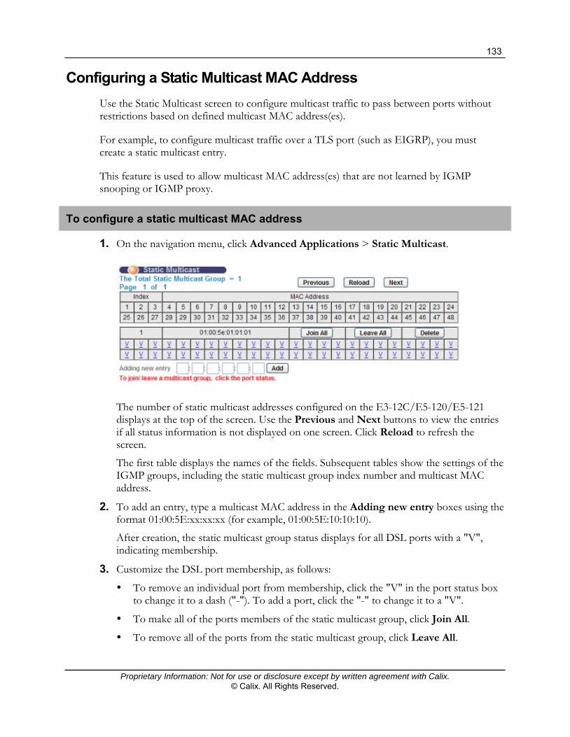
133
Proprietary Information: Not for use or disclosure except by written agreement with Calix. © Calix. All Rights Reserved.
Configuring a Static Multicast MAC Address
Use the Static Multicast screen to configure multicast traffic to pass between ports without restrictions based on defined multicast MAC address(es).
For example, to configure multicast traffic over a TLS port (such as EIGRP), you must create a static multicast entry.
This feature is used to allow multicast MAC address(es) that are not learned by IGMP snooping or IGMP proxy.
To configure a static multicast MAC address
1. On the navigation menu, click Advanced Applications > Static Multicast.
The number of static multicast addresses configured on the E3-12C/E5-120/E5-121 displays at the top of the screen. Use the Previous and Next buttons to view the entries if all status information is not displayed on one screen. Click Reload to refresh the screen.
The first table displays the names of the fields. Subsequent tables show the settings of the IGMP groups, including the static multicast group index number and multicast MAC address.
2. To add an entry, type a multicast MAC address in the Adding new entry boxes using the format 01:00:5E:xx:xx:xx (for example, 01:00:5E:10:10:10).
After creation, the static multicast group status displays for all DSL ports with a "V", indicating membership.
3. Customize the DSL port membership, as follows:
To remove an individual port from membership, click the "V" in the port status box to change it to a dash ("-"). To add a port, click the "-" to change it to a "V".
To make all of the ports members of the static multicast group, click Join All.
To remove all of the ports from the static multicast group, click Leave All.

134
Proprietary Information: Not for use or disclosure except by written agreement with Calix. © Calix. All Rights Reserved.
4. Click Add to save the settings to volatile memory.
Calix recommends periodically saving configuration changes to non-volatile memory using the Config Save option on the navigation menu.
To delete a static multicast MAC entry
1. In the table with the MAC address you are deleting, click Delete to remove the static multicast group.
Static Multicast Screen
Use the Static Multicast screen to view and configure static multicast entries on the E3-12C/E5-120/E5-121.
To open the Static Multicast screen
On the navigation menu, click Advanced Applications > Static Multicast.
The following table describes the elements of the Static Multicast screen:
Label Description
The Number of Static Multicast
The number of static multicast entries configured on the E3-12C/E5-120/E5-121.
Page x of x Identifies which page of information is displayed and the total number of pages of information.
Previous
Next
Use these buttons to scroll to the previous or next screen if all status information is not displayed on one screen.
Reload Click Reload to refresh the screen.
The first table displays the names of the fields. Subsequent tables show the settings of the IGMP groups.
Index The static multicast group index number.
MAC Address The multicast MAC address.

135
Proprietary Information: Not for use or disclosure except by written agreement with Calix. © Calix. All Rights Reserved.
Label Description
1 through xx Display the static multicast group membership status of the DSL ports.
"V" displays for members and "-" displays for non-members.
Click a port’s status to change it (clicking a "V" changes it to "-" and vice versa).
Join All Click Join All to make all of the DSL ports members of the static multicast group.
Leave All Click Leave All to remove all of the DSL ports from the static multicast group.
Delete Click Delete to remove a static multicast group.
VID
Adding new entry
Add
In the VID box, type the VLAN on which the multicast MAC address was received, or type 0 (zero) if the entry applies to all VLANs.
In the MAC box, type a multicast MAC address using the format 01:00:5E:xx:xx:xx (for example, 01:00:5E:10:10:10).
Click Add to save the settings to volatile memory.
Calix recommends periodically saving configuration changes to non-volatile memory using the Config Save option on the navigation menu.

136
Proprietary Information: Not for use or disclosure except by written agreement with Calix. © Calix. All Rights Reserved.

Proprietary Information: Not for use or disclosure except by written agreement with Calix. © Calix. All Rights Reserved.
Chapter 6
Configuring Video Services
This section presents the following provisioning models and information for video service:
Video and data model for residential gateway (RG) support xDSL video and data support using standard, static VLANs VDSL video and data support using a multicast VLAN (MVLAN) for multicast video
traffic IGMP settings and statistics
The procedures in this section describe how to turn up xDSL video services using the E3-12C/E5-120/E5-121 Web interface.

138
Proprietary Information: Not for use or disclosure except by written agreement with Calix. © Calix. All Rights Reserved.
Residential Gateway Support
Please note the following configuration guidelines:
RG Support, Core-Network Services Separation
In this model, video and data traffic at the RG is untagged, and services are separated at the core network.
The E3-12C/E5-120/E5-121 Ethernet switch honors the DSCP priority settings configured on the RG.
IGMP prioritization is handled by the RG. The RG model presented in this section assumes that subscriber traffic is double-tagged
in the E3-12C/E5-120/E5-121 uplink upstream direction.
The following diagram shows the elements required to configure Residential Gateway (RG) services on the E3-12C/E5-120/E5-121:

139
Proprietary Information: Not for use or disclosure except by written agreement with Calix. © Calix. All Rights Reserved.
Additional reference topics
For information about DSCP activation and mapping, see DSCP (on page 242).
Provisioning Checklist: Residential Gateway Services
Use the checklists below to provision Residential Gateway (RG) service for an xDSL port.
Starting point
Before starting the configuration process, check that the following conditions in the following table are met.
Description Reference
Verify that the Ethernet uplink is installed and configured, SFP modules are installed, and fibers are connected.
Verify that the correct switch priority queue is applied to the multicast and unicast VLANs. Note: Typically, switch priority queue settings do not need to be modified.
Configuring the Ethernet Links (on page 49)
Setting Up the Switch (on page 59)
Verify that the DSL subscriber interfaces are wired.
Have on hand the following information:
The multicast and unicast VLAN IDs to use for RG services
(For any ports using ADSL) The VPI/VCI values used by the subscriber CPE
(Per site requirements) Configure bonding groups. Configuring Bonding Groups (on page 216)
Turn-up process
The service turn-up process includes the steps in the following table.
Description Reference
Create a single static VLAN for unicast data and video STB traffic and assign membership.
Assign PVID values to each port receiving RG services.
Create a VLAN for Unicast Subscriber Traffic (on page 141)
Create a multicast VLAN and assign membership and configure a multicast VLAN group.
Creating the Multicast VLAN (on page 143)
Set the IGMP mode to IGMP proxy, configure IGMP settings, and add the multicast VLAN to the static query VLAN table.
IGMP Proxy Settings for Residential Gateway Services (on page 175)
(For VDSL ports) Configure double tagging. Follow the procedure for VDSL ports in Configuring Double Tagging: Residential Gateway Services (on page 119)
(For ports operating in ADSL fallback mode) Configure the virtual channel (VC) and DT PVC settings.
Applying VC Parameters to xDSL Ports for Residential Gateway Service (on page 149)
Follow the procedure for ADSL fallback ports in Configuring Double Tagging: Residential Gateway Services (on page 119)

140
Proprietary Information: Not for use or disclosure except by written agreement with Calix. © Calix. All Rights Reserved.
Next steps
The following tasks can be performed based on per-site or per-subscriber port requirements:
Configure DHCP settings (on page 218) or PPPoA-to-PPPoE conversions (on page 225) for the data VLAN.
To limit subscriber access to specific multicast addresses, create IGMP profiles and apply them to ports. See Creating and Modifying IGMP Profiles (on page 64).
For information about DSCP priority bit activation and mapping, see DSCP (on page 242).
To define port operation settings, create an xDSL port profile and apply them to ports. You can also configure port attributes such as SNR and line rate settings. See Creating xDSL Profiles (on page 69) and Customizing xDSL Port Settings (on page 232).
To define xDSL port alarm thresholds, create xDSL alarm profiles and apply them to ports. See Creating xDSL Alarm Profiles (on page 77).

141
Proprietary Information: Not for use or disclosure except by written agreement with Calix. © Calix. All Rights Reserved.
Creating a VLAN for Unicast Subscriber Traffic
For a checklist of provisioning steps, refer to the Provisioning Checklist: Residential Gateway Services (on page 139).
This topic describes how to create a single VLAN for unicast video traffic.
To configure the subscriber VLAN for unicast traffic and assign membership
1. In the Navigation menu, click Advanced Applications > VLAN.
2. Click the Static VLAN Settings tab, and then do the following:
a. Make sure the Active checkbox is selected.
b. In the Name box, type a descriptive name for this VLAN group for identification purposes (up to 31 characters; spaces are not allowed). Example: Unicast_Video200.

142
Proprietary Information: Not for use or disclosure except by written agreement with Calix. © Calix. All Rights Reserved.
c. Type the VLAN ID for this static VLAN entry (from 1 to 4094). Example: VLAN ID=200.
d. In the Control column, select ENET and xDSL ports as Fixed for the ports to be permanent members of this VLAN.
e. At the bottom of the screen, click Add.
3. Click the VLAN Port Settings tab, and then do the following:
a. In the PVID boxes for the ports identified, type the . Example: PVID for port 1 = 2001 to PVID for port 12 = 2012 (or for port 24 = 2024).
The E3-12C/E5-120/E5-121 assigns the PVID to untagged frames or priority frames (0 VID) received on this port.
b. In the Priority list for the ports identified, accept the default setting (0).
4. At the bottom of the screen, click Apply to save your changes to E3-12C/E5-120/E5-121 volatile memory.
Additional reference topics
Viewing VLAN Statuses (on page 284) Editing and Deleting Static VLANs (on page 286)

143
Proprietary Information: Not for use or disclosure except by written agreement with Calix. © Calix. All Rights Reserved.
Creating a Multicast VLAN and Group
For a checklist of provisioning steps, refer to the Provisioning Checklist: Residential Gateway Services (on page 139).
Use the MVLAN Setup screen to configure basic settings and port members for a multicast VLAN.
To create a multicast VLAN
1. On the navigation menu, click Advanced Applications > Multicast VLAN.
2. Click the MVLAN Setup tab.
Note: Clicking Cancel resets the screen values.
3. Select the Active check box to enable service on the multicast VLAN.

144
Proprietary Information: Not for use or disclosure except by written agreement with Calix. © Calix. All Rights Reserved.
4. In the Name box, type a descriptive name for the multicast VLAN (up to 31 printable ASCII characters; spaces are not allowed). Example: Name=Multicast_RG100.
5. In the VLAN box, type the VLAN ID of the multicast VLAN (from 1 to 4094). Example: VLAN ID=100.
6. In the port list below the VLAN ID field, do the following:
a. Under the Control column, select the Fixed radio button to the right of the ENET1 and ENET2 ports and to the right of each subscriber port that will be a permanent member of this multicast VLAN. (Click Select All to include every port.)
To prohibit a subscriber port from joining this multicast VLAN, select Forbidden.
b. Under the Tagging column, select the TX Tagging radio button to the right of the ENET1 and ENET2 ports.
With this setting, the E3-12C/E5-120/E5-121 adds an IEEE 802.1Q tag to frames transmitted with this VLAN ID.
7. At the bottom of the screen, click Add.
8. Click the MVLAN Group tab.
Note: Clicking Cancel resets the screen values.
9. In the MVLAN list, select the multicast VLAN ID you created above. Example: MVLAN ID=100.
10. In the Index list, select the index number for the multicast VLAN group or range of multicast IP addresses to configure.

145
Proprietary Information: Not for use or disclosure except by written agreement with Calix. © Calix. All Rights Reserved.
11. In the Start Multicast IP box, type the beginning of the range of multicast IP addresses. Example: Start Multicast IP=225.0.0.0.
12. In the End Multicast IP box, type the end of the range of multicast IP addresses. Example: Start Multicast IP=235.255.255.255.
13. Click Apply to save the settings to E3-12C/E5-120/E5-121 volatile memory.
Calix recommends periodically saving configuration changes to non-volatile memory using the Config Save option on the navigation menu.
14. At the bottom of the screen, in the MVLAN list select the multicast VLAN to view the multicast IP addresses assigned to it. Under the list, the State displays whether the select multicast VLAN is active (Enable) or inactive (Disable).
Additional reference topics
Viewing MVLAN Statuses (on page 287) Editing and Deleting MVLANs (on page 288) Editing and Deleting an MVLAN Group (on page 288)
Configuring Double Tagging: Residential Gateway Services
For a checklist of provisioning steps, see the Provisioning Checklist: Residential Gateway Services (on page 139).
This topic describes how to configure double tagging (DT) for a VDSL port or an ADSL port that is configured for Residential Gateway service.
The purpose of double tagging is to receive untagged traffic from the subscriber and add a stacked double tag to it before sending the traffic to the uplink. In this stacked double-tag structure, the outer tag is the Service VLAN ID (S-VID) and the inner tag from the subscriber is the Customer VLAN ID (C-VID).
Configuration guidelines
When configuring a subscriber port for double-tagging, use the following guidelines:
The CPE modem must be configured as untagged. MAC Forced-Forwarding (MACFF) must be disabled on the port/VLAN. ACL profiles are not supported on ports with double tagging enabled. Any combination of DT S-VID and C-VID must be unique in the system.
To configure double-tagging for VDSL ports
1. On the navigation menu, click Advanced Applications > DT.
2. In the DT tab, and then do the following:

146
Proprietary Information: Not for use or disclosure except by written agreement with Calix. © Calix. All Rights Reserved.
Note: In the above illustration, DT entries have been created for ports 1 and 2, and the DT entry for port 3 is in progress (S-tag VID 200; C-tag VID 2003).
Clicking Cancel resets the parameters at the top of the screen.
a. In the port list, select an xDSL port for the double-tagging entry that you are creating or editing.
b. In the S-tag VID box, type the service VLAN ID (S-VID).
c. In the S-tag Priority list, accept the default setting (0).
d. In the C-tag VID box, type the PVID.
e. In the C-tag Priority list, accept the default setting (0).
f. Select the DT Enable check box.
3. Click Add or Apply to save the settings to volatile memory.
Calix recommends periodically saving configuration changes to non-volatile memory using the Config Save option on the navigation menu.

147
Proprietary Information: Not for use or disclosure except by written agreement with Calix. © Calix. All Rights Reserved.
The DT-related information for the port displays in the table at the bottom of the screen. A "V" in the Enable column indicates that the entry is activated.
To edit a DT entry, repeat the steps in the above procedure to override the current DT settings for the port.
To clear a DT entry, repeat the steps in the above procedure, except at Step 2f, clear the DT Enable check box.
To configure a double-tagged PVC for ADSL fallback mode
1. On the navigation menu, click Advanced Applications > DT.
2. Click the DT PVC tab, and then do the following:

148
Proprietary Information: Not for use or disclosure except by written agreement with Calix. © Calix. All Rights Reserved.
Note: In the above illustration, DT PVC entries have been created for ports 1 and 2, and the DT PVC entry for port 3 is in progress (VPI/VCI=0/35; S-tag VID 200; C-tag VID 2003).
Clicking Cancel resets the parameters at the top of the screen.
a. In the port list, select an xDSL port to set up a DT PVC.
b. In the VPI box, type the Virtual Path Identifier for a channel on this port.
c. In the VCI box, type the Virtual Circuit Identifier for a channel on this port.
d. In the IP QoS Profile list, select the IP QoS profile to classify and prioritize application traffic flowing through this DT PVC.
e. In the Encap list, select the encapsulation method (typically LLC) to apply to this channel.
f. In the S-tag VID box, type the Service VLAN ID (S-VID).
g. In the S-tag Priority list, accept the default value (0).
h. In the C-tag VID box, type PVID for the port as the Customer VLAN ID (C-VID).
i. In the C-tag Priority list, accept the default value (0).
j. Select the Super Channel check box.
3. Click Add or Apply to save the settings to volatile memory.
Calix recommends periodically saving configuration changes to non-volatile memory using the Config Save option on the navigation menu.
The PVC index number and related information display in the table at the bottom of the page. Use the Show Port list to select which ports' PVC settings to display in the table in the bottom half of the screen. A "V" in the Super column indicates that the entry is set up as a super channel.
From the DT PVC screen, you can view the PPPoE-to-PPPoA status for each PVC by clicking the index number of the PVC. For more information, see Viewing the PPPoE-to-PPPoA Status for a PVC (on page 228).
To edit or delete a DT PVC
1. On the navigation menu, click Advanced Applications > DT.
2. Click the DT PVC tab.
3. To edit a DT PVC, do the following:
a. In the Port list, select the port with the DT PVC to edit.
b. Enter or select the parameters for the DT PVC.
c. Click Apply.

149
Proprietary Information: Not for use or disclosure except by written agreement with Calix. © Calix. All Rights Reserved.
4. To delete DT PVCs, do the following:
a. In the Select column, select each DT PVC entry to delete. To select all entries, at the bottom of the screen, click All. (To clear all entries, click None.)
5. At the bottom of the screen, click Delete.
Applying VC Parameters to xDSL Ports for Residential Gateway Service
This topic describes how to set up VC parameters for an xDSL port operating in ADSL fallback mode for Residential Gateway service.
You can optionally configure the E3-12C/E5-120/E5-121 to detect PPPoE/PPPoA encapsulation and view the PPPoE-to-PPPoA status for a configured VC.
To create a VC for a subscriber port
1. On the navigation menu, click Basic Settings > xDSL Port Setup.
2. Click the VC Setup tab, and then do the following:
Note: Clicking Cancel before clicking Apply resets the VC settings.
a. In the Port list, select the xDSL port to configure.
b. Select the Super Channel check box for Residential Gateway configuration.

150
Proprietary Information: Not for use or disclosure except by written agreement with Calix. © Calix. All Rights Reserved.
c. In the VPI and VCI boxes, enter the VPI and VCI assigned to the modem. For example, in the VPI box, type 0 and in the VCI box, type 35.
d. In the IP QoS Profile list, select an IP QoS profile to associate with the VC settings for classifying and prioritizing application traffic.
e. In the Encap list, select the encapsulation type (typically LLC) for the VC.
Note: When the Super Channel check box is selected, the PVID fields are disabled.
f. If PPPoA-to-PPPoE conversion is set up on the port, select the Auto Detect check box.
When the check box is selected, the AC Name and Service Name fields are enabled:
Optionally specify the host name of a remote access concentrator if there are two access concentrators (or BRAS) on the network or if you want to allow PAE translation to the specified access concentrator. In this case, the E3-12C/E5-120/E5-121 checks the AC name field in the BRAS's reply PDU. If there is a mismatch, the E3-12C/E5-120/E5-121 drops this PDU. (This is not recorded as an PPPoE AC System Error in the PPPoA to PPPoE Status screen.)
Optionally specify the name of the service that uses this PVC. This must be a service name that you configure on the remote access concentrator.
3. Click Add or Apply to save the settings to volatile memory.
Calix recommends periodically saving configuration changes to non-volatile memory using the Config Save option on the navigation menu.
The VC displays in the index list at the bottom of the page. Use the Show Port list to display a list VCs for a specific port or all ports.
Note: An asterisk displays in the PVID and Priority columns if the VC is configured as a super channel.
Related topic
Editing, Deleting, and Copying VCs (on page 240)

151
Proprietary Information: Not for use or disclosure except by written agreement with Calix. © Calix. All Rights Reserved.
xDSL Video and Data Support: Static VLAN Model
In the VLAN-per-service model (N:1 VLAN model), multiple subscriber ports are assigned to a standard VLAN for a single service. Multicast video traffic can be assigned to a common, shared (secure) VLAN. The VLAN-per-service model provides the following features and advantages:
Streamlines network provisioning and minimizes VLAN management. Provides a unique VLAN for every service (subscribers and services share a common
VLAN). Enables distributed access network element and service management. The standard VLAN model is required for premium Video-on-Demand (VOD) services.
Note: Calix recommends using unique multicast MAC addresses across your channel lineup to prevent potential overload issues.
Unlike unicast traffic, multicast traffic (broadcast video, music, EPG data, and STB boot information) enters the E3-12C/E5-120/E5-121 on a dedicated VLAN. The E3-12C/E5-120/E5-121 then distributes the multicast streams to the appropriate DSL ports based on IGMP leave and join requests. The upstream router receives the IGMP messages and responds by sending the appropriate video streams.
Video Provisioning Checklist: xDSL, Static VLAN Model
This checklist assumes that you are provisioning unicast video and data service offerings for customers when not using a residential gateway.
Starting point
Before starting the configuration process, check that the conditions in the following table are met.
Description Reference
Verify that the Ethernet uplink is installed and configured, SFP modules are installed, and fibers are connected.
Verify that the correct switch priority queue is applied to the VLANs. Note: Typically, switch priority queue settings do not need to be modified.
Configuring the Ethernet Links (on page 49)
Setting Up the Switch (on page 59)
Verify that the DSL subscriber interfaces are wired.
Gather xDSL port setting requirements to create custom xDSL port profiles.
Gather subscriber template attributes. For ports using ADSL mode, have on hand the VPI/VCI values used by the subscriber CPE.
Have on hand the VLAN ID(s) to use for data and video services.

152
Proprietary Information: Not for use or disclosure except by written agreement with Calix. © Calix. All Rights Reserved.
Description Reference
Configure bonding groups, if required. Configuring Bonding Groups (on page 216)
Turn-up process
The service turn-up process includes the steps in the following table.
Description Reference
(Recommended) Enable IGMP proxy.
To set up IGMP proxy for the first time, follow the recommendations for configuring IGMP settings.
For more information about IGMP, see the Calix E3-12C/E5-100 Engineering and Planning Guide.
Enable IGMP Proxy (on page 175)
IGMP Proxy Setup Considerations: Standard Video VLAN Models (on page 177)
Create a data VLAN and video VLAN and assign membership. Configuring the Service VLAN and Assigning VLAN Membership (on page 153)
Create xDSL port profiles to define port operation settings and apply them to ports.
Creating xDSL Profiles (ADSL/VDSL) (on page 67)
Sample xDSL Profiles (on page 71)
Configure xDSL port settings. Configuring xDSL Port Settings (E5-12x video) (on page 154)
Next steps
The following tasks can be performed based on per-site or per-subscriber port requirements:
Configure DHCP settings for the data VLAN. See DHCP Relay (on page 218). For subscriber CPEs operating in ADSL mode, configure VC parameters and apply
settings to a set of xDSL ports. See Apply VC Parameters to xDSL Ports (on page 238). To limit subscriber access to specific multicast addresses, create IGMP profiles and apply
them to ports. See Creating and Modifying IGMP Profiles (on page 64) and Assign IGMP Profiles to xDSL Ports (on page 66).
Configure MAC forced-forwarding (MACFF) rules. See Configuring MACFF Settings (on page 248).
For information about DSCP priority bit activation and mapping, see DSCP (on page 242).
To classify and prioritize data traffic for each data service plan and apply them to ports, create IP QoS profiles (on page 74).
To classify and perform actions on the upstream data and video traffic, create ACL profiles (on page 80). See also Applying ACL Profiles to a Set of xDSL Ports (on page 83).
To customize port operation settings, create configure port attributes such as SNR and line rate settings. See Customizing xDSL Port Settings (on page 232).
To define xDSL port alarm thresholds, create xDSL alarm profiles and apply them to ports. See Creating xDSL Alarm Profiles (on page 77).

153
Proprietary Information: Not for use or disclosure except by written agreement with Calix. © Calix. All Rights Reserved.
Configuring the Service VLAN and Assigning VLAN Membership
For a checklist of provisioning steps, see the Video Provisioning Checklist: xDSL, Standard VLAN Model (on page 151).
This topic describes how to create a VLAN for video services and set whether Ethernet ports propagate VLAN information to other devices. This configuration uses the VLAN-per-service data model.
If you are also configuring data service, and have not already done so, follow the procedure to create a data service VLAN:
Configuring the Data Service VLAN and Assigning VLAN Membership (on page 108)
To configure the vide service VLAN and assign VLAN membership
1. In the Navigation menu, click Advanced Applications > VLAN.
2. Click the Static VLAN Settings tab, and then do the following:
a. Make sure the Active checkbox is selected.
b. In the Name box, type a descriptive name for this VLAN group for identification purposes.
Note: Spaces are not allowed in the name.
c. Type the VLAN ID for this static VLAN entry; the valid range is between 1 and 4094.
d. In the Control column, select ENET and xDSL ports as Fixed for the ports to be permanent members of this VLAN.
e. In the Tagging column, set the tagging parameters appropriately.
For ENET1 and ENET2 ports, select the Tx Tagging check box (tagged).
For xDSL ports, select the Tx Tagging check box or leave it clear (untagged) based on site requirements. Note the following: ♦ For VDSL services, traffic can be tagged or untagged on the xDSL port, and
this setting must match the configuration of the VDSL modem. ♦ When provisioning both data and video services over VDSL, you have two
options: 1) set the xDSL port tagged for one service and leave the other untagged; or 2) set both services to tagged.
f. Click Add.
154
Proprietary Information: Not for use or disclosure except by written agreement with Calix. © Calix. All Rights Reserved.
3. (For VDSL ports only) Click the VLAN Port Settings tab, and then do the following:
a. In the PVID box for the port identified, type the Port VLAN ID (PVID) to assign to untagged, upstream traffic or priority frames (0 VID).
b. In the Priority list for the port identified, select an IEEE 802.1p priority to assign to untagged frames or priority frames (0 VID) received on this port.
c. At the bottom of the screen, click Apply to save the settings to E3-12C/E5-120/E5-121 volatile memory. Calix recommends periodically saving configuration changes to non-volatile memory using the Config Save option on the navigation menu.
Additional reference topics
Viewing VLAN Statuses (on page 284) Editing and Deleting Static VLANs (on page 286)
Configuring xDSL Port Settings
For a checklist of provisioning steps, see the Video Provisioning Checklist: xDSL, Standard VLAN Model (on page 151).
This topic describes how to configure xDSL port settings and apply any previously-created xDSL, xDSL alarm, IGMP, and IP QoS profiles.
After you have configured one port, you can optionally copy the port settings to multiple xDSL ports.
To configure the xDSL port settings
1. On the navigation menu, click Basic Settings > xDSL Port Setup.
2. On the xDSL Port Setup tab, do the following:
a. Under the Port column, click the link to the port you are configuring.
b. Select the Active check box to enable the port.
c. In the Customer Info box, type information to identify the subscriber connected to the ADSL port (up to 31 characters; spaces and hyphens are allowed).
d. In the Customer Tel box, type information to identify the telephone number of the subscriber connected to the port (up to 15 characters; spaces and hyphens are allowed).
e. In the Profile list, select a profile of xDSL settings (transfer rates, latency mode and interleave delay, and signal-to-noise ratio settings) to assign to the port.
f. In the Mode area of the screen, select the port’s operational mode based on subscriber’s CPE:

155
Proprietary Information: Not for use or disclosure except by written agreement with Calix. © Calix. All Rights Reserved.
Note: By default, auto is selected for the E3-12C/E5-120/E5-121 to automatically determine the mode to use.
To select VDSL2 with a specific ADSL fallback mode, click one of the VDSL2 + fall back options in the first column, under Auto.
To select a VDSL2-only profile (8a, 8b, 8c, 8d, 12a, 12b, 17a), in the second column of options, select the profile, or select VDSL2 for the E3-12C/E5-120/E5-121 to automatically determine the VDSL2 profile to use.
To select an ADSL standard, click one of the service types in the third column of options.
g. If you have created an alarm profile to use, in the Alarm Profile list, select the profile to define alarm thresholds for the xDSL port. The E3-12C/E5-120/E5-121 sends an alarm trap and generates a syslog entry when the thresholds of the alarm profile are exceeded.
h. In the IGMP Profile list, select a profile of IGMP settings to assign to the port. The profile restricts subscriber access to specified IGMP multicast groups.
i. In the IP QoS Profile list, select a profile to assign to the data service offering. The profile groups and prioritizes application traffic in queues for downstream direction (toward CPE devices) and fine-tunes network performance.
3. In the Advanced Features area you can customize the following xDSL port settings:
Note: Not all CPE chipsets support the advanced features on the xDSL Port Settings screen. For interoperability questions, refer to the E3-12C/E5-120/E5-121 Release Notes or check with Calix Technical Assistance Center (TAC).
a. In the Option Mark area, select one or more option masks (clicking the ALL check box selects all option mask selections):
Disable one or more of these settings: Trellis, Reed-Solomon, Upstream Bitswap, Downstream Bitswap, 1-bit Constellation, Transmit Windowing, s=0.5 Support (ADSL1 only).
Enable one or more of these settings: Nitro, ADSL2 Annex L, ADSL2+ Annex M, upstream point-to-multipoint (US PTM) optimization, downstream PTM optimization, upstream PhyR, and downstream PhyR.
b. Enable, disable, or select these settings: RFI Band, Limit Mask, Seamless Rate Adaptation (SRA), minimum impulse noise protection (Min INP), and the upstream and downstream power-back-off (UPBO and DPBO).
c. In the RFI Custom area, use the Enable check box and the Start and End boxes to activate customized RFI band start and end frequencies.
4. Click Add or Apply to save your changes to the system volatile memory.
5. (Recommended) On the navigation menu, use the Config Save option to save changes to non-volatile memory.

156
Proprietary Information: Not for use or disclosure except by written agreement with Calix. © Calix. All Rights Reserved.
To copy port settings to other port(s)
1. In the Copy port list, select the port from which you want to copy the settings.
2. Click Paste.
The following screen opens.
3. Select to which ports you want to copy the settings.
All selects every port.
None clears all of the check boxes.
4. Click Apply to paste the settings.
5. On the navigation menu, use the Config Save option to save your changes to non-volatile memory.
Related topics
Creating xDSL Profiles (on page 67) Creating xDSL Alarm Profiles (on page 77) Creating IGMP Profiles (on page 64) Creating IP QoS Profiles (on page 74)

157
Proprietary Information: Not for use or disclosure except by written agreement with Calix. © Calix. All Rights Reserved.
VDSL Video and Data Support: Multicast VLAN Model
A multicast VLAN is used to distribute a single copy of stream across an E3-12C/ E5-120/E5-121 (Layer-2) network while allowing segmentation of STB broadcast domains for scaling and troubleshooting purposes. This optimizes bandwidth usage by reducing multicast traffic in the subscriber VLANs and simplifying multicast group management.
A multicast VLAN translates IGMP messages to a target service VLAN based on the IP multicast group address. After the translation, IGMP runs on the target VLAN and the unicast video runs on the original service VLAN.
Downstream traffic in the multicast VLAN is assigned to the PVID VLAN (for untagged subscriber traffic) by default. For CPE with a service VLAN, downstream traffic can be directed to a specified VLAN using a downstream-only VLAN translation rule, and the PVID is not used.
Optionally, the unicast video VLAN can be transported across the E3-12C/E5-120/E5-121 network using VLAN translation on the uplink device or double tagging on the E3-12C/ E5-120/E5-121.
Since the E3-12C/E5-120/E5-121 might change the subscriber VLAN ID to the multicast VLAN ID, both the subscriber port and the Ethernet port should be members of the multicast VLAN.
Note: Premium video-on-demand (VOD) service requires a unicast VLAN for IGMP traffic; for this service, the static VLAN model must be used.
The E3-12C/E5-120/E5-121 supports Multicast VLAN video configurations for both tagged (VLAN-aware) and untagged (VLAN-unaware) CPE.

158
Proprietary Information: Not for use or disclosure except by written agreement with Calix. © Calix. All Rights Reserved.
Video Provisioning Checklist: VDSL, Multicast VLAN Model
Use the checklists below to provision multicast VLAN service for VDSL ports when a residential gateway is not used. Review the appropriate overview to understand the required provisioning objects:
E3-12C/E5-120/E5-121 Configuration Guidelines and Process: VDSL with Tagged CPE (on page 159)
E3-12C/E5-120/E5-121 Configuration Guidelines and Process: VDSL with Untagged CPE (on page 162)
Starting point
Before starting the configuration process, check that the following conditions in the following table are met.
Description Reference
Verify that the Ethernet uplink is installed and configured, SFP modules are installed, and fibers are connected.
Verify that the correct switch priority queue is applied to the multicast and unicast VLANs. Note: Typically, switch priority queue settings do not need to be modified.
Configuring the Ethernet Links (on page 49)
Setting Up the Switch (on page 59)
Verify that the DSL subscriber interfaces are wired.
Have on hand the following information:
The multicast and unicast VLAN IDs to use for services
(For CPE with tagged traffic) the CPE VLAN IDs used for video and data services
(Per site requirements) Configure bonding groups. Configuring Bonding Groups (on page 216)
Turn-up process
The service turn-up process includes the steps in the following table.
Description Reference
Create a multicast VLAN and assign membership and configure a multicast VLAN group.
Creating a Multicast VLAN and Multicast VLAN Group (on page 166)
Create a static VLAN for video STB traffic and assign membership.
(For untagged CPEs) Assign the PVID value to each port receiving services.
Note: For tagged CPEs, the PVID assignments are not used.
Create a VLAN for Unicast Subscriber Traffic (on page 141)
Create a static VLAN for data service and assign membership. Create a VLAN for Unicast Data Traffic (on page 171)
(For tagged CPEs) Configure VLAN translation rules for each subscriber port receiving service.
Setting Up VLAN Translation Rules for Tagged-CPE Traffic (on page 172)

159
Proprietary Information: Not for use or disclosure except by written agreement with Calix. © Calix. All Rights Reserved.
Description Reference
Set the IGMP mode to IGMP proxy, configure IGMP settings, and add the multicast VLAN to the static query VLAN table.
Setting the IGMP Mode (on page 175)
IGMP Proxy Setup Considerations (on page 177)
Next steps
The following tasks can be performed based on per-site or per-subscriber port requirements:
Configure DHCP settings (on page 218) or PPPoA-to-PPPoE conversions (on page 225) for the unicast data VLAN.
To limit subscriber access to specific multicast addresses, create IGMP profiles and apply them to ports. See Creating and Modifying IGMP Profiles (on page 64).
For information about DSCP priority bit activation and mapping, see DSCP (on page 242).
To define port operation settings, create an xDSL port profile and apply them to ports. You can also configure port attributes such as SNR and line rate settings. See Creating xDSL Profiles (on page 69) and Customizing xDSL Port Settings (on page 232).
To define xDSL port alarm thresholds, create xDSL alarm profiles and apply them to ports. See Creating xDSL Alarm Profiles (on page 77).
E3-12C/E5-120/E5-121 Configuration Guidelines and Process: VDSL with Tagged CPE
In this model, video and data traffic is tagged, and services are separated at the E3-12C/E5-120/E5-121 service unit. Note the following:
All VDSL modems can be configured with the same VLAN settings (in this example, VLAN 5 for video and VLAN 3 for data).
The VLAN ID for video on the VDSL CPE may be the same as or different than the video VLAN ID created on the E3-12C/E5-120/E5-121. The illustration below shows an example in which the CPE video VLAN ID is different than the video service VLANs.
VLAN translation is used for multicast video traffic in the downstream direction only. Upstream mapping is automatically handled by the multicast VLAN.
Subscriber traffic is tagged in the E3-12C/E5-120/121 uplink, upstream direction. Since CPE traffic is tagged, the PVID value for the port is ignored.

160
Proprietary Information: Not for use or disclosure except by written agreement with Calix. © Calix. All Rights Reserved.
Starting point
Verify that the Ethernet uplink is installed and configured (uplink port in service), SFP modules are installed, and fibers are connected.
Verify that the DSL subscriber interfaces are wired. Configure bonding groups, if required. Have on hand the following information:
CPE VLAN IDs used for video and data service.
Multicast and unicast VLAN IDs to use for services. (This example uses MVLAN 503, video unicast VLAN 506, and unicast data VLAN 504.)

161
Proprietary Information: Not for use or disclosure except by written agreement with Calix. © Calix. All Rights Reserved.
Configuration process
To configure the E3-12C/E5-120/E5-121 for video service using an MVLAN (tagged CPE)
1. For multicast video traffic, create a Multicast VLAN with the following settings:
VLAN ID = 503 (example)
ENET port memberships: Fixed and Tx Tagging enabled
xDSL port memberships: Fixed and Tx Tagging disabled*
* If the multicast VLAN is extended to the DSL modem without translation, enable Tx tagging.
2. Create an MVLAN group for the MVLAN ID (in this example, VLAN ID 503) with the expected range of multicast IP addresses.
3. For unicast video traffic, create a static unicast VLAN with the following settings:
VLAN ID = 506 (example)
ENET port memberships: Fixed and Tx Tagging enabled
xDSL port memberships: Fixed and Tx Tagging disabled*
* If the unicast VLAN is extended to the DSL modem without translation, enable Tx tagging.
Note: The assigned PVID value (on the VLAN Port Settings screen) is not used.
4. For data traffic, create a static unicast VLAN with the following settings:
VLAN ID = 504 (example)
ENET port memberships: Fixed and Tx Tagging enabled
xDSL port memberships: Fixed and Tx Tagging enabled
5. Configure VLAN translation rules for each port:
Add a downstream-only VLAN translation rule to translate the multicast VLAN ID to the CPE video VLAN ID (example: translate VLAN ID 503 DS traffic to VLAN ID 5).*
Add a bi-directional VLAN translation rule to translate the unicast video VLAN ID to the CPE VLAN video ID (example: translate VLAN ID 506 to VLAN ID 5).*
Add a bidirectional VLAN translation rule to translate the unicast data VLAN ID to the CPE data VLAN ID (example: translate VLAN ID 504 to VLAN ID 3).
* If the video service VLAN ID on the CPE matches the VLAN ID configured in Step 1 or Step 3 above, a corresponding translation rule is not required.
6. Configure DHCP settings for the unicast data VLAN.

162
Proprietary Information: Not for use or disclosure except by written agreement with Calix. © Calix. All Rights Reserved.
7. Configure the following IGMP proxy settings:
IGMP Mode = Proxy
IGMP Version = V2
Leave Message Handling Mode = Last Member Query
Audit Query = enabled (check box selected)
Add Static Query VLAN = <Multicast VLAN ID> = 503 (example)
Add Static Query VLAN = <Unicast Video VLAN ID> = 506 (example)
Next steps
Verify that the correct switch priority queue (among the switch setup parameters) is applied to the multicast and static/unicast VLANs.
Note: Typically, switch priority queue settings do not need to be modified.
Create and apply profiles to xDSL ports, as required:
(Optional) Create IGMP profiles to limit subscriber access to specific multicast addresses, and apply them to ports.
Create an xDSL port profile to define port operation settings, and apply to ports.
Create xDSL alarm profiles that define xDSL port alarm thresholds, and apply them to ports.
(Per site requirements) Configure port attributes such as customized SNR and line rate settings.
E3-12C/E5-120/E5-121 Configuration Guidelines and Process: VDSL with Untagged CPE
In this model, video and data traffic is tagged, and services are separated at the E5-12C/E5-120/E5-121 service unit. Note the following:
Downstream multicast traffic from the multicast source is automatically forwarded by the multicast VLAN (in this example, VLAN 503).
Middleware, DHCP, and VOD run on a static unicast video VLAN (in this example, VLAN 506).
Internet/data traffic uses a separate static unicast data VLAN (in this example, VLAN 504)
Untagged subscriber traffic in the E3-12C/E5-120/E5-121 uplink, upstream direction is assigned the PVID value (in this example, PVID 506).

163
Proprietary Information: Not for use or disclosure except by written agreement with Calix. © Calix. All Rights Reserved.
Starting point
Verify that the Ethernet uplink is installed and configured (uplink port in service), SFP modules are installed, and fibers are connected.
Verify that the DSL subscriber interfaces are wired. Configure bonding groups, if required. Have on hand the multicast and unicast VLAN IDs to use for services. (This example
uses MVLAN 503, video unicast VLAN 506, and unicast data VLAN 504.)

164
Proprietary Information: Not for use or disclosure except by written agreement with Calix. © Calix. All Rights Reserved.
Configuration process
To configure the E3-12C/E5-120/E5-121 for video service using an MVLAN (untagged CPE)
1. For multicast video traffic, create a Multicast VLAN with the following settings:
VLAN ID = 503 (example)
ENET port memberships: Fixed and Tx Tagging enabled
xDSL port memberships: Fixed and Tx Tagging disabled
2. Create an MVLAN group for the MVLAN ID (in this example, VLAN ID 503) with the expected range of multicast IP addresses.
3. For unicast video traffic, create a static unicast VLAN with the following settings:
VLAN ID = 506 (example)
ENET port memberships: Fixed and Tx Tagging enabled
xDSL port memberships: Fixed and Tx Tagging disabled
4. Set the VLAN Port Settings as follows:
For the PVID value, use the same value as the unicast video VLAN ID (in the example, 506).
For the Priority setting, use the value for video traffic as defined for the switch (in this example, 5).
5. For data traffic, create a static unicast VLAN with the following settings:
VLAN ID = 504 (example)
ENET port memberships: Fixed and Tx Tagging enabled
xDSL port memberships: Fixed and Tx Tagging enabled
6. Configure DHCP settings for the unicast data VLAN.
7. Configure the following IGMP proxy settings:
IGMP Mode = Proxy
IGMP Version = V2
Leave Message Handling Mode = Last Member Query
Audit Query = enabled (check box selected)
Add Static Query VLAN = <Multicast VLAN ID> = 503 (example)
Add Static Query VLAN = <Unicast Video VLAN ID> = 506 (example)

165
Proprietary Information: Not for use or disclosure except by written agreement with Calix. © Calix. All Rights Reserved.
Next steps
Verify that the correct switch priority queue (among the switch setup parameters) is applied to the multicast and static/unicast VLANs.
Note: Typically, switch priority queue settings do not need to be modified.
Create and apply profiles to xDSL ports, as required:
(Optional) Create IGMP profiles to limit subscriber access to specific multicast addresses, and apply them to ports.
Create an xDSL port profile to define port operation settings, and apply to ports.
Create xDSL alarm profiles that define xDSL port alarm thresholds, and apply them to ports.
(Per site requirements) Configure port attributes such as customized SNR and line rate settings.

166
Proprietary Information: Not for use or disclosure except by written agreement with Calix. © Calix. All Rights Reserved.
Creating a Multicast VLAN and Group
For a checklist of provisioning steps, refer to the Video Provisioning Checklist: VDSL, Multicast VLAN Model (on page 158).
Use the MVLAN Setup screen to configure basic settings and port members for a multicast VLAN.
To create a multicast VLAN
1. On the navigation menu, click Advanced Applications > Multicast VLAN.
Note: Clicking Cancel resets the screen values.
2. Select the Active check box to enable service on the multicast VLAN.
3. In the Name box, type a descriptive name for the multicast VLAN (up to 31 printable ASCII characters; spaces are not allowed). Example: Name=Multicast_100.

167
Proprietary Information: Not for use or disclosure except by written agreement with Calix. © Calix. All Rights Reserved.
4. In the VLAN box, type the VLAN ID of the multicast VLAN (from 1 to 4094). Example: VLAN ID=100.
5. In the port list below the VLAN ID field, do the following:
a. Under the Control column, select Fixed to the right of the ENET1 and ENET2 ports and to the right of each subscriber port that will be a permanent member of this multicast VLAN. (Click Select All to include every port.)
To prohibit a subscriber port from joining this multicast VLAN, select Forbidden.
b. Under the Tagging column, select TX Tagging to the right of the ENET1 and ENET2 ports. (The E3-12C/E5-120/E5-121 adds an IEEE 802.1Q tag to frames transmitted with this VLAN ID.)
c. For VDSL subscriber ports, do one of the following:
Leave the Tx Tagging check box clear (unchecked) for untagged CPE traffic or CPE traffic that requires a VLAN translation.
Enable Tx Tagging if the multicast VLAN is extended to the DSL modem without translation (that is, if the video service VLAN configured on the CPE matches the VLAN ID of this multicast VLAN).
6. At the bottom of the screen, click Add.
7. Click the MVLAN Setup tab.
Note: Clicking Cancel resets the screen values.
8. In the MVLAN list, select the multicast VLAN ID you created above. Example: MVLAN ID=100.

168
Proprietary Information: Not for use or disclosure except by written agreement with Calix. © Calix. All Rights Reserved.
9. In the Index list, select the index number for the multicast VLAN group or range of multicast IP addresses to configure.
10. In the Start Multicast IP box, type the beginning of the range of multicast IP addresses. Example: Start Multicast IP=225.0.0.0.
11. In the End Multicast IP box, type the end of the range of multicast IP addresses. Example: Start Multicast IP=235.255.255.255.
12. Click Apply to save the settings to volatile memory.
Calix recommends periodically saving configuration changes to non-volatile memory using the Config Save option on the navigation menu.
At the bottom of the screen, in the MVLAN list select the multicast VLAN to view the multicast IP addresses assigned to it. Under the list, the State displays whether the select multicast VLAN is active (Enable) or inactive (Disable).
Additional reference topics
Viewing MVLAN Statuses (on page 287) Editing and Deleting MVLANs (on page 288) Editing and Deleting an MVLAN Group (on page 288)
Creating a VLAN for Unicast Video Traffic
For a checklist of provisioning steps, refer to the Video Provisioning Checklist: VDSL, Multicast VLAN Model (on page 158).
This topic describes how to create a single VLAN for unicast video traffic.
To configure the VLAN for subscriber unicast video traffic and assign membership
1. In the Navigation menu, click Advanced Applications > VLAN.
2. Click the Static VLAN Settings tab, and then do the following:

169
Proprietary Information: Not for use or disclosure except by written agreement with Calix. © Calix. All Rights Reserved.
a. Make sure the Active checkbox is selected.
b. In the Name box, type a descriptive name for this VLAN group for identification purposes (up to 31 characters; spaces are not allowed). Example: Unicast_Vid_506.
c. Type the VLAN ID for this static VLAN entry (from 1 to 4094). Example: VLAN ID=506.
d. In the Control column, select ENET and xDSL ports as Fixed for the ports to be permanent members of this VLAN.
e. For VDSL subscriber ports, do one of the following:
Leave the Tx Tagging check box clear (unchecked) for untagged CPE traffic or tagged CPE traffic that requires a VLAN translation.
Enable Tx Tagging if the unicast VLAN is extended to the DSL modem without translation (that is, if the video service VLAN configured on the CPE matches the VLAN ID of this static VLAN).
f. At the bottom of the screen, click Add.

170
Proprietary Information: Not for use or disclosure except by written agreement with Calix. © Calix. All Rights Reserved.
3. If you are setting up video for tagged CPEs, the procedure is complete.
If you are setting up video for untagged CPEs, click the VLAN Port Settings tab, and then do the following:
a. In the PVID boxes for the ports identified, type the same VLAN ID as the unicast video VLAN (in this example, 506).
b. For the Priority setting lists, use the value defined for video traffic (in this example, 5).
Tip: Use the Copy port list to copy the PVID and Priority values from one port to multiple ports.
4. At the bottom of the screen, click Apply to save your changes to E3-12C/E5-120/E5-121 volatile memory.
Additional reference topics
Viewing VLAN Statuses (on page 284) Editing and Deleting Static VLANs (on page 286)
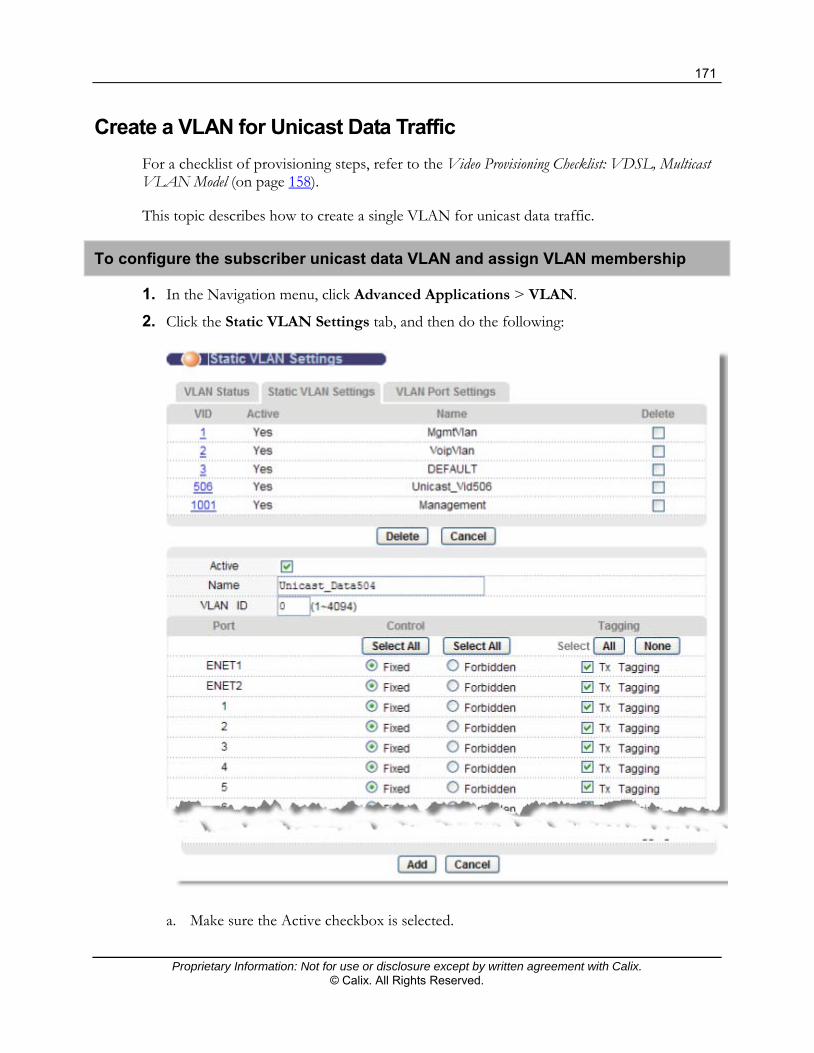
171
Proprietary Information: Not for use or disclosure except by written agreement with Calix. © Calix. All Rights Reserved.
Create a VLAN for Unicast Data Traffic
For a checklist of provisioning steps, refer to the Video Provisioning Checklist: VDSL, Multicast VLAN Model (on page 158).
This topic describes how to create a single VLAN for unicast data traffic.
To configure the subscriber unicast data VLAN and assign VLAN membership
1. In the Navigation menu, click Advanced Applications > VLAN.
2. Click the Static VLAN Settings tab, and then do the following:
a. Make sure the Active checkbox is selected.

172
Proprietary Information: Not for use or disclosure except by written agreement with Calix. © Calix. All Rights Reserved.
b. In the Name box, type a descriptive name for this VLAN group for identification purposes (up to 31 characters; spaces are not allowed). Example: Unicast_Data504.
c. Type the VLAN ID for this static VLAN entry (from 1 to 4094). Example: VLAN ID=504.
d. In the Control column, select ENET and xDSL ports as Fixed for the ports to be permanent members of this VLAN.
e. In the Tagging column, select Tx Tagging for all ports that are members of this VLAN.
3. Click Add to save the settings to volatile memory.
Calix recommends periodically saving configuration changes to non-volatile memory using the Config Save option on the navigation menu.
Additional reference topics
Viewing VLAN Statuses (on page 284) Editing and Deleting Static VLANs (on page 286)
Setting Up VLAN Translation Rules for Tagged CPE Traffic
For a checklist of provisioning steps, refer to the Video Provisioning Checklist: VDSL, Multicast VLAN Model (on page 158).
In the VLAN Translation screen, you can set up the VLAN translation rules for required tag actions.
Important: VLAN translation parameter definitions for the E3-12C/E5-120/E5-121 differ from other Calix products. Be sure that you are familiar with them.
Parameter definitions for single-tagged traffic
The CXVID is the expected VLAN ID/tag received on the subscriber port (for tagged CPE traffic), or use zero (0) for untagged CPE traffic.
The CVID is the VLAN ID/tag that the CXVID will be translated into. Since there is only one tag, the CVID is the service provider's VLAN ID/tag.
The SVID is set to zero (0) to represent single-tagged traffic.
Parameter definitions for double-tagged traffic
The CXVID is the expected VLAN ID/tag received on the subscriber port (for tagged CPE traffic), or use zero (0) for untagged CPE traffic.
The CVID is the VLAN ID/tag that the CXVID will be translated into. Since there are two tags (outer tag and inner tag), the CVID is the inner VLAN ID/C-tag.
The SVID is the outer VLAN ID/S-tag.

173
Proprietary Information: Not for use or disclosure except by written agreement with Calix. © Calix. All Rights Reserved.
Notes: The following procedure assumes that you are setting up video and data traffic with single-tagged traffic and that the video service VLAN ID configured on the CPE is not the same as the video unicast VLAN ID or the multicast VLAN ID.
In cases where the video service VLAN ID on the CPE matches one of the video service VLAN IDs configured on the E3-12C/E3-120/E5-121, you would not create a corresponding translation rule (in Step 2a or Step 2b).
For double-tagged traffic, refer to the parameter definitions above to determine the values for the SVID, CVID, and CXVID fields.
Single-tagged traffic: Setting up VLAN translation rules for tagged CPE traffic
1. On the navigation menu, click Advanced Applications > VLAN Translation.
Note: Clicking Cancel clears the screen of changes without saving them.
2. In the Port list, select a member xDSL subscriber port, and then do the following:
a. Create a bi-directional VLAN translation rule for unicast video traffic:
In the SVID box, type zero (0) to create a rule for single-tagged traffic.
In the CVID box, type the VLAN ID of the unicast video VLAN.
In the CXVID box, type the VLAN ID used on the CPE for video traffic.
Leave the Downstream only check box cleared (not selected).

174
Proprietary Information: Not for use or disclosure except by written agreement with Calix. © Calix. All Rights Reserved.
b. Create a downstream-only VLAN translation rule for the multicast video VLAN:
In the SVID box, type zero (0) to create a rule for single-tagged traffic.
In the CVID box, type the VLAN ID of the multicast VLAN.
In the CXVID box, type the VLAN ID used on the CPE for video traffic.
Select the Downstream only check box.
c. Create a bi-directional VLAN translation rule for data traffic:
In the SVID box, type zero (0) to create a rule for single-tagged traffic.
In the CVID box, type the VLAN ID of the unicast data VLAN.
In the CXVID box, type the VLAN ID used on the CPE for data traffic.
Leave the Downstream only check box cleared (not selected).
3. Click Apply to save the settings to volatile memory.
4. Repeat Steps 2 and 3 for each xDSL port that is receiving services.
5. Calix recommends periodically saving configuration changes to non-volatile memory using the Config Save option on the navigation menu.
In the bottom half of the screen, view the ports for which you have configured VLAN translation rules.
*/* displayed in the VPI and VCI columns indicates that the VLAN translation rules are applied to all channels on the port.
<-> displayed in the Direction column indicates that VLAN translation is applied to both downstream and upstream traffic
-> indicates that VLAN translation is only applied to downstream traffic.

175
Proprietary Information: Not for use or disclosure except by written agreement with Calix. © Calix. All Rights Reserved.
IGMP Settings and Statistics
This section covers the following topics:
Enabling IGMP Proxy IGMP Proxy settings for residential gateway support IGMP Proxy settings for standard video VLAN models IGMP configuration options Viewing IGMP status Viewing multicast groups for IGMP port joins Viewing IGMP port counters
Enabling IGMP Proxy
The factory default IGMP mode is set to Disabled. Use the following procedure to configure the E3-12C/E5-120/E5-121 to perform IGMP proxy.
To enable IGMP Proxy
1. On the navigation menu, click Advanced Applications > IGMP.
2. Click the Config tab, and then do the following:
a. In the IGMP Mode list, select Proxy.
b. In the IGMP Version list, select the version of IGMP to support.
c. Review the applicable topic below and adjust the IGMP proxy settings per site requirements.
d. Click Apply to save the settings.
Reference topics
IGMP Proxy Settings: Residential Gateway Support (on page 175) IGMP Proxy Settings: Standard Video VLAN Models (on page 177)
IGMP Proxy Settings: Residential Gateway Services
This topic describes how to configure IGMP settings for Residential Gateway (RG) services. To optimize video performance, apply settings based on site requirements.
Note: Before completing this procedure, verify that the CPE device is not performing IGMP proxy functions.

176
Proprietary Information: Not for use or disclosure except by written agreement with Calix. © Calix. All Rights Reserved.
To configure IGMP proxy settings for RG services
1. In the E3-12C/E5-120/E5-121 Configurator, click Advanced Applications > IGMP.
2. Click the Config tab.

177
Proprietary Information: Not for use or disclosure except by written agreement with Calix. © Calix. All Rights Reserved.
3. At the top of the screen, do the following:
a. In the IGMP Mode list, select Proxy.
b. In the IGMP Version list, select V2.
c. Below the IGMP Mode list, click Apply.
4. In the Leave Message Handling area, do the following:
a. Verify that the Leave Message Handling Mode list is set to Last Member Query.
b. Increase the Leave Message Handling Query Interval to 3 (300 ms) to compensate for the slower response of STBs in generating an IGMP group query report.
c. Below the Leave Message Handling area of the screen, click Apply.
5. In the Audit Query area of the screen, do the following:
a. Clear the Enable check box to disable the audit query.
b. Below the Audit Query area of the screen, click Apply.
6. In the Add Static Query VLAN box, do the following:
a. Type the multicast VLAN ID. Example: Add Static Query VLAN=100.
b. To the right of the box, click Apply.
7. (Recommended) On the navigation menu, use the Config Save option to save your changes to non-volatile memory.
IGMP Proxy Settings: Standard Video VLAN Models
This topic describes how to troubleshoot video tiling or dropped video streams after enabling IGMP proxy for customers when not using a residential gateway. To optimize video performance, apply settings based on site requirements.
In the management interface, after setting the IGMP mode to IGMP proxy, check the following:
In the Audit Query area of the IGMP Configuration screen, verify that the Enable check box is selected.
If video tiling occurs, increase the Audit Query Interval in increments of 100 ms, up to 300 ms.
If video tiling persists, increase the Audit Query Robustness setting from 2 to 3.
Note: The Audit Query Interval and Audit Query Robustness settings are interrelated. The E3-12C/E5-120/E5-121 multiplies the query interval by the robustness value to determine how long to wait for a response before dropping a video stream from the query group.
Important: Increasing the Audit Query Interval and Robustness values can result in longer channel-change times.

178
Proprietary Information: Not for use or disclosure except by written agreement with Calix. © Calix. All Rights Reserved.
Other IGMP proxy settings
Calix recommends using these factory default IGMP Mode and Leave Message Handling parameter settings:
IGMP Mode default settings
IGMP Version: V2 Query Interval: 60 seconds Robustness: 2 Query Response Interval: 10000 ms (10 seconds)
Leave Message Handling default settings
Leave Message Handling Mode: Last Member Query Query Interval: 100 ms Robustness: 2
IGMP Configuration Options
The following table describes the IGMP Config screen elements for reference.
Label Description
IGMP Mode Use Proxy mode to manually specify multicast groups.
Use Snooping mode to have the device passively learn multicast groups.
When Disable is selected, the device does not use either IGMP proxy or snooping.
IGMP Version Sets the version of IGMP to support: IGMPv2 (V2) or IGMPv3 (V3).
When IGMPv2 is selected, the device discards IGMPv3 packets. This setting provides better security if none of the devices in the network use IGMPv3. When IGMPv3 is selected, the device recognizes both IGMPv2 and IGMPv3.
Query Interval Sets how often the E3-12C/E5-120/E5-121 sends a general query message in IGMP proxy mode (10 to 1000 seconds).
The [query interval] x [robustness] + [query response interval] indicates the maximum number of seconds that a multicast member can be active in a multicast group if before the next IGMP query for the group is received. The default value is 60.
Robustness Sets the value (1 to 5) to indicate how susceptible the subnet is to lost packets. Use a higher value when a higher number of lost packets are expected. The factory default value is 2.

179
Proprietary Information: Not for use or disclosure except by written agreement with Calix. © Calix. All Rights Reserved.
Label Description
Query Response Interval
Sets the maximum number of milliseconds (100 to 10000, in 100-ms increments) for how long the E3-12C/E5-120/E5-121 waits for a response to a general query message.
Leave Message Handling Mode
Last Member Query (factory default) generates a group-specific query to check if any other hosts require the channel before issuing an IGMP leave message.
Immediate Leave removes a port from the multicast table as soon as an IGMP leave report is received.
Query Interval When Leave Message Handling Mode is set to Last Member Query, the query response interval (100, 200, 300, 400, or 500 milliseconds) can be customized.
Robustness When Leave Message Handling Mode is set to Last Member Query, the IGMP robustness value (1 to 5) can be customized.
Audit Query Enable Selecting the Enable check box turns on the IGMP audit query; clearing the check box disables it.
Audit Query Interval
Sets the query interval for IGMP audit query (100, 200, 300, or 400 milliseconds).
Audit Query Robustness
Sets the robustness value for IGMP audit query (1 to 5).
Static Query VLAN Table
Use the Add Static Query VLAN field to add a VLAN ID the Static Query VID table for IGMP proxy mode.
Tip: Adding the video VLAN ID to this table reduces the delay in re-learning the uplink information following an E3-12C/E5-120/E5-121 power cycle.
To remove the entry from the Static Query VID table, select the Select check box to the right of the VLAN ID and click Delete.
Dynamic Query VID Table
When IGMP proxy is enabled, the video VLAN ID that has been dynamically learned displays in this table.

180
Proprietary Information: Not for use or disclosure except by written agreement with Calix. © Calix. All Rights Reserved.
Viewing IGMP Status
Use the IGMP Status screen to view current IGMP information. This screen displays the following statistics:
Query: The total number of Query packets received. Report: The total number of Report packets received. Leave: The total number of Leave packets received. Number of IGMP Groups: The number IGMP groups the E3-12C/E5-120/E5-121
has identified on the local network.
In the table in the lower half on the screen, view the VLAN ID on which the IGMP group is created, the IP address of an IP multicast group member, and the ports that are members of the IGMP snooping group.
To open the IGMP Status tab
1. On the navigation menu, click Advanced Applications > IGMP.
2. Click the Status tab.
3. Click Reload to refresh the screen.
4. To navigate when more than one IGMP group index is available, click Next (or Previous).
The IGMP group index number displays in the table. "Page x of x" identifies which page is currently displayed and the total number of pages available to view.
5. (Optional) Click Clear to delete the information the E3-12C/E5-120/E5-121 has learned about multicast groups and reset the counters on screen.
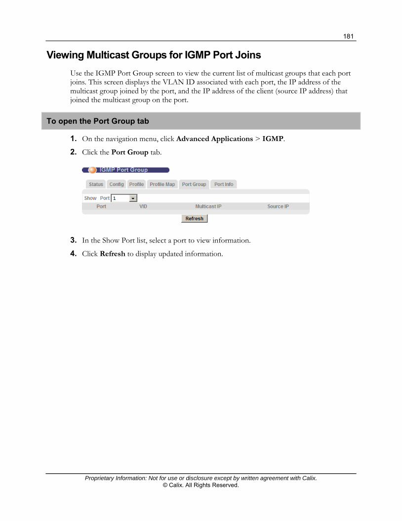
181
Proprietary Information: Not for use or disclosure except by written agreement with Calix. © Calix. All Rights Reserved.
Viewing Multicast Groups for IGMP Port Joins
Use the IGMP Port Group screen to view the current list of multicast groups that each port joins. This screen displays the VLAN ID associated with each port, the IP address of the multicast group joined by the port, and the IP address of the client (source IP address) that joined the multicast group on the port.
To open the Port Group tab
1. On the navigation menu, click Advanced Applications > IGMP.
2. Click the Port Group tab.
3. In the Show Port list, select a port to view information.
4. Click Refresh to display updated information.

182
Proprietary Information: Not for use or disclosure except by written agreement with Calix. © Calix. All Rights Reserved.
Viewing IGMP Port Counters
Use the IGMP Port Info screen to view the current number of IGMP-related packets received on each port. This screen displays the following:
Group Count: Total number of Group packets received on the port(s). Query Count: Total number of Query packets received on the port(s). Join Count: Total number of Join packets received on the port(s). Leave Count: Total number of Leave packets received on the port(s). Audit Leave Count: Total number of Leave packets received during the audit query
interval.
To open the IGMP Port Info tab
1. On the navigation menu, click Advanced Applications > IGMP.
2. Click the Port Info tab.
3. In the Show Port, list, select a port to view information, or select All to to view
information for all ports.
4. (Optional) Click Clear to delete the information the E3-12C/E5-120/E5-121 has learned about multicast groups and reset each counter.

Proprietary Information: Not for use or disclosure except by written agreement with Calix. © Calix. All Rights Reserved.
Chapter 7
Configuring VoIP Services (E3-12C/E5-121 Only)
This section describes how to turn-up an E3-12C/E5-121 for a VoIP service from the Web user interface.
This chapter covers the following configuration tasks:
A checklist for the E3-12C/E5-121 VoIP services configuration process Configuring the VoIP mode Setting the VoIP interface Configuring the service VLAN and assigning membership Configuring SIP and TDM Gateway subscriber service Configuring H.248 service
Additional reference topics
Active Call Screen (on page 203) Using Call Services (on page 207) Setting Up Distinctive Ringing (on page 213)

184
Proprietary Information: Not for use or disclosure except by written agreement with Calix. © Calix. All Rights Reserved.
VoIP Services Checklist for E3-12C/E5-121
This overview describes how to turn-up an E3-12C/E5-121 for VoIP service.
Starting point
Before starting the configuration process, check that the following conditions are met.
Description Reference
Verify that the Ethernet uplink is installed and configured, SFP modules are installed, and fibers are connected.
Configuring the Ethernet Links (on page 49)
Set the VoIP mode to the type of service to be provisioned: SIP, C7 TDM Gateway, or H.248.
Setting the VoIP Mode (on page 185)
Have on hand the VLAN ID to use for VoIP services.
Turn-up process for SIP and TDM Gateway Service
The VoIP service turn-up process for SIP or TDM Gateway VoIP service includes the steps in the following table. You should have on hand the following information:
VoIP telephone number (for SIP mode) or GR-303/GR-8 IG CRV (for C7 TDM Gateway mode)
IP address of your VoIP provider’s SIP server (For SIP VoIP mode only) The IP address or domain name of the SIP registrar server
and IP address or domain name of the SIP server or outbound proxy SIP server, if supplied by the VoIP service provider.
For SIP service, voice traffic must be routed through an external media gateway. See External Media Gateway for SIP VoIP Traffic (on page 62).
Description Reference
For SIP VoIP service, create a number table plan. Creating a SIP Numbering Plan (on page 89)
Create SIP, call service, and DSP profiles. Creating VoIP Service Profiles (on page 87)
Set up the VoIP VLAN and VoIP IP address (or DHCP client mode). Setting the VoIP Interface (on page 186)
Configure the service VLAN and assign membership. Configuring the Service VLAN and Assigning Membership (on page 187)
Configure the subscriber service.
Note: Both loop start and ground start GSFN modes are supported. By default all VoIP ports use loop start.
Configuring SIP and TDM Gateway Subscriber Service (on page 190)

185
Proprietary Information: Not for use or disclosure except by written agreement with Calix. © Calix. All Rights Reserved.
Turn-up process for H.248 Service
The VoIP service turn-up process for H.248 VoIP service includes the steps in the following table. You should have on hand the IP address or domain name and port number of the H.248 Media Gateway Controller (MGC).
Description Reference
Create DSP and H.248 profiles. Creating VoIP Service Profiles (on page 87)
Configure and enable the Media Gateway. Configuring the Media Gateway (on page 194)
Set up the VoIP VLAN and VoIP IP address. Setting the VoIP Interface (on page 186)
Configure the service VLAN and assign membership. Configuring the Service VLAN and Assigning Membership (on page 187)
Configure the subscriber service. Configuring H.248 Subscriber Service (on page 195)
Setting the VoIP Mode
Use the VoIP Mode screen to configure which mode to use for VoIP settings:
SIP C7 TDM Gateway H.248
To open the Mode screen
1. On the navigation menu, click VoIP > Mode.
2. In the Mode list, select the mode.
3. Click Apply to save your change.

186
Proprietary Information: Not for use or disclosure except by written agreement with Calix. © Calix. All Rights Reserved.
Setting the VoIP Interface
This topic describes how to configure the VoIP IP setup for management of the E3-12C/E5-121. For instructions on setting up the Ethernet and default management gateway fields, see Configuring the Initial Setup (on page 30).
Ensure that your VoIP IP settings match your overall network scheme.
To set the VoIP VLAN and VoIP IP address
1. On the navigation menu, click Basic Settings > IP Setup to open the IP Setup screen.
2. In the VoIP section of the IP Setup page, do the following:
Note: Clicking Cancel before clicking Apply VoIP Settings resets the fields to the currently-saved settings.
a. Do one of the following:
To use DHCP to obtain a dynamic IP, select the DHCP Client Mode check box and skip to Step 2f.
To configure a static VoIP VLAN interface, continue with Step 2b.

187
Proprietary Information: Not for use or disclosure except by written agreement with Calix. © Calix. All Rights Reserved.
b. In the IP box, type the E3-12C/E5-121’s VoIP service IP address, in dotted decimal notation.
c. In the IP mask box, type the subnet mask for the E3-12C/E5-121’s VoIP IP address, in dotted decimal notation.
d. In the Default VoIP Gateway box, type the IP address of the default outgoing gateway for VoIP service, if required.
e. In the DNS box, type the IP address of the Domain Name System server for VoIP service, if required.
Note: For SIP service, the DNS server IP address is required if the SIP server uses domain names in SIP messages.
f. In the VLAN ID box, type the VLAN ID for VoIP service.
3. Click Add or Apply to save your changes to the system volatile memory.
4. (Recommended) On the navigation menu, use the Config Save option to save changes to non-volatile memory.
Configuring the Service VLAN and Assigning Membership
This topic describes how to configure a VLAN for VoIP services and set whether Ethernet ports propagate VLAN information to other devices.
The E3-12C/E5-121 can add IEEE 802.1Q VLAN ID tags to voice frames that it sends to the network. This allows the E3-12C/E5-121 to communicate with a SIP server that is a member of the same VLAN group. Some ISPs use the VLAN tag to identify voice traffic and give it priority over other traffic.
To configure the service VLAN and assign VLAN membership
1. In the Navigation menu, click Advanced Applications > VLAN > Static VLAN Settings.
2. In the Static VLAN Settings page, do the following:
a. Make sure the Active checkbox is selected.
b. In the Name box, type a descriptive name for this VLAN group for identification purposes (spaces are not permitted). Example: Voip_Vlan.
c. Enter the VLAN ID of the VLAN used for VoIP services on the E3-12C/E5-121.

188
Proprietary Information: Not for use or disclosure except by written agreement with Calix. © Calix. All Rights Reserved.
d. In the ENET1 and ENET2 port rows, do the following:
For the Control column, select Fixed for the ports to be permanent members of this VLAN.
For the Tagging column, select the Tx Tagging check boxes (tagged) for the port to tag all outgoing frames transmitted with this VLAN ID.
e. In the xDSL port rows, do the following:
For the Control column, select Forbidden to prohibit the port from joining the VLAN group.
For Tagging column, leave the Tx Tagging check box clear (untagged).
Note: Individual xDSL ports do not need access to the VoIP VLAN, since the E3-12C/E5-121 converts VoIP to an analog dial tone service before sending it to individual subscriber ports.
f. Click Add.
3. On the navigation menu, click Advanced Applications > VLAN > VLAN Port Settings.
4. In the VLAN Port Settings page, do the following:
a. In the PVID box for the port identified, enter the Port VLAN ID (PVID) from 1 to 4094.
The E3-12C/E5-121 assigns the PVID to untagged frames or priority frames (0 VID) received on this port.
b. In the Priority box for the port identified, select an IEEE 802.1p priority to assign to untagged frames or priority frames (0 VID) received on this port.
5. Click Add or Apply to save the settings to volatile memory.
6. Calix recommends periodically saving configuration changes to non-volatile memory using the Config Save option on the navigation menu.
To copy port settings to other port(s)
1. In the Copy port list, select the port from which you want to copy the settings.
2. Click Paste.

189
Proprietary Information: Not for use or disclosure except by written agreement with Calix. © Calix. All Rights Reserved.
The following screen opens.
3. Select to which ports you want to copy the settings.
All selects every port.
None clears all of the check boxes.
4. Click Apply to paste the settings.
5. On the navigation menu, use the Config Save option to save your changes to non-volatile memory.

190
Proprietary Information: Not for use or disclosure except by written agreement with Calix. © Calix. All Rights Reserved.
Configuring SIP and TDM Gateway Subscriber Service
This topic describes how to configure VoIP settings for E3-12C/E5-121 VoIP ports.
Use the VoIP Port Setup screen to activate VoIP ports and apply the following previously-created profiles:
SIP profile Call service profile DSP profile
Use the same screen to disable VoIP ports.
You can optionally override the SIP and call service profile settings on a per-line basis based on site requirements and company practices and procedures.
The customer telephone number assigned to the port displays at the top of the screen.

191
Proprietary Information: Not for use or disclosure except by written agreement with Calix. © Calix. All Rights Reserved.
To configure VoIP subscriber service
1. On the navigation menu, click VoIP > VoIP Port Setup.
2. In the Port View tab, under the Index column, click the link for the port to configure.
The Port Edit tab opens.
Note: Clicking Cancel before clicking Apply resets the parameter values to the previously-saved settings.
a. Select the Enable check box to enable VoIP on the port.
b. In the VoIP Tel Number box, type the applicable information.
If the VoIP mode is SIP, enter the subscriber line ID according to the URI format specified in the SIP profile: ♦ If the URI type = SIP, enter the subscriber's SIP user name (for example,
jlocke). ♦ If the URI type = Tel, enter the subscriber's telephone number (for example,
5558675309). If the VoIP mode is C7 TDM Gateway, enter the CRV or channel ID for the
subscriber line, as provisioned on the C7 GR-303 or GR-8 interface group (for example, N1-1-IG1-224; the format is case sensitive).
c. In the SIP Profile list, select the SIP profile to use.
d. In the Call Service Profile list, select the call service profile to use.
e. In the DSP Profile list, select the digital signal processing profile to use.
f. In the TX Gain box, type the DSP transmit gain range (–200 to 200, in 0.1-dB increments). The default is 0 dB.
g. In the RX Gain box, type the DSP receive gain range (–200 to 200, in 0.1-dB increments). The default is –20 (–2 dB).
h. In the Seizure Mode list, select the general signaling function (GSFN): Ground Start or Loop Start. By default, Loop Start is selected.
Note: The Ground start GSFN is supported for GR-57, GR-303, and D4 formats.
i. In the Authorization Mode list and Call Services Mode lists, leave the setting at profile to use the profile settings selected in Steps 2c and 2d.
To override the profile settings for this port, select line and customize the settings per your site requirements.
3. Click Add or Apply to save your changes to the system volatile memory.
(Recommended) On the navigation menu, use the Config Save option to save changes to non-volatile memory.

192
Proprietary Information: Not for use or disclosure except by written agreement with Calix. © Calix. All Rights Reserved.
To disable VoIP subscriber service
1. On the navigation menu, click VoIP > VoIP Port Setup.
2. In the Port View tab, under the Index column, click the link for the port to configure.
The Port Edit tab opens.
3. Clear the Enable check box to disable VoIP service on the port.
4. If you are clearing the customer telephone information from the port, in the VoIP Tel Number box, delete the information.
5. Click Add or Apply to save your changes to the system volatile memory.
(Recommended) On the navigation menu, use the Config Save option to save changes to non-volatile memory.
Port View Screen (SIP)
Use the Port View screen to view details of the VoIP settings configured on all E3-12C/E5-121 ports. From this screen you can also change the SIP profile, Digital Signal Processing (DSP) profile and call service profile each port uses, as well as copy the VoIP settings from one port to other ports.
To open the Port View tab
1. On the navigation menu, click VoIP > VoIP Port Setup.
2. Click the Port View tab.
The following table describes the labels in the Port View tab:
Label Description
Port The port number. Click a number to go to that port’s Port Edit screen, where you can configure customer and profile information.
Active Select this to activate VoIP on the port.
Customer Name If you configured a name in the Basic Setting > xDSL Port Setup > xDSL Port Setting screen’s Customer Info field, it displays here.
SIP Profile Select the SIP profile the port is to use. If you have not configured any profiles, only the default profile DEFVAL can be selected. Configure SIP profiles in the VoIP > SIP Profile screen.

193
Proprietary Information: Not for use or disclosure except by written agreement with Calix. © Calix. All Rights Reserved.
Label Description
VoIP Tel Number The subscriber line ID, CRV, or channel ID for the subscriber line you configured in the Port Edit screen displays here.
DSP Profile The name of the Digital Signal Processing (DSP) profile used by the specified port displays here. Configure DSP profiles in the VoIP > DSP Profile screen.
Call Service Profile Select the call service profile the port is to use. If you have not configured any profiles, only the default profile DEFVAL can be selected. Configure call service profiles in the VoIP > Call Service Profile screen.
DSP TX/RX Gain The Digital Signal Processing (DSP) transmission and receiving gain values used for each subscriber port.
From Select the From radio button to prepare to copy the specified port’s settings to all the other ports. Click the Copy button to complete the procedure.
Apply Click Apply to save the settings to the system volatile memory.
Calix recommends periodically saving configuration changes to non-volatile memory using the Config Save option on the navigation menu.
Copy Click Copy to copy VoIP settings from the selected port to all other ports. You must first select a port’s Copy From radio button.
Cancel Click Cancel to return the fields in this screen to their last-saved values.

194
Proprietary Information: Not for use or disclosure except by written agreement with Calix. © Calix. All Rights Reserved.
Configuring H.248 Service
Setting up H.248 services involves these steps:
Set the VoIP mode to H.248. Configure and enable the Media Gateway. Configure DSP profiles. Configure H.248 profiles. Configure and enable VoIP ports.
Softswitch setup notes
Customer telephone numbers are set up at the softswitch. To maintain an accurate connection status between the softswitch and the E3-12C/E5-
121, be sure that the softswitch's Keep Alive is enabled.
Reference topics
Setting the VoIP Mode (on page 185) DSP profiles (on page 99) H.248 profiles (on page 101)
Configuring the Media Gateway
Use VoIP Media Gateway screen to configure and enable an H.248 media gateway.

195
Proprietary Information: Not for use or disclosure except by written agreement with Calix. © Calix. All Rights Reserved.
To configure the media gateway
1. On the navigation menu, click VoIP > Media Gateway.
2. Select the Enable check box.
3. In the MG Name/IP box, type one of the following, as required by the softswitch:
The media gateway's IP address
The system appends the value in the MG Name/IP field with the value in the Port Number field and sends it as the Media Gateway Identifier with the following format: [IP_address]:port_number.
The media gateway's fully qualified DNS name (up to 31 characters in length)
The system appends the value in the MG Name/IP field with the value in the Port Number field and sends it as the Media Gateway Identifier with the following format: [DNS_name]:port_number.
4. In the Port box, type the media gateway port number (1025 to 65535) to use.
5. In the H.248 Profile list, select the profile to use.
6. Click Apply to save the settings.
Configuring H.248 Subscriber Service
Use the procedure below to configure the VoIP settings of each of the E3-12C/E5-121 ports and apply a previously-created DSP profile.
The customer name, termination name, and MG name assigned to the VoIP port display at the top of the screen.

196
Proprietary Information: Not for use or disclosure except by written agreement with Calix. © Calix. All Rights Reserved.
To configure VoIP subscriber service
1. On the navigation menu, click VoIP > VoIP Port Setup.
2. Click the Port Edit tab, and do the following:
Note: Clicking Cancel before clicking Apply resets the parameter values to the previously-saved settings.
a. In the Port list, select the port to configure.
b. Select the Enable check box to enable VoIP on the port.
c. In the DSP Profile list, select the digital signal processing profile to use.
d. (Optional) In the VBD Profile list, select the DSP profile to use for modem/FAX calls. If you do not select a profile, the profile selected in the DSP Profile list is used for modem/FAX calls.
e. In the TX Gain box, type the DSP transmit gain range (–200 through 200, in 0.1-dB increments). The default is 0 dB.
f. In the RX Gain box, type the DSP receive gain range (–200 through 200, in 0.1-dB increments). The default is –20 (–2 dB).
3. Click Add or Apply to save the settings to volatile memory.
4. Calix recommends periodically saving configuration changes to non-volatile memory using the Config Save option on the navigation menu.
VoIP Port View Screen (H.248)
Use the VoIP Port View screen to view details of the VoIP settings configured on all of the E3-12C/E5-121’s ports. You can also change the Digital Signal Processing (DSP) profile and VBD profile each port uses, and copy the VoIP settings from one port to all the other ports.
To open the Port View tab
1. On the navigation menu, click VoIP > VoIP Port Setup.
2. Click the Port View tab.
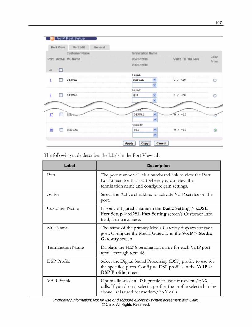
197
Proprietary Information: Not for use or disclosure except by written agreement with Calix. © Calix. All Rights Reserved.
The following table describes the labels in the Port View tab:
Label Description
Port The port number. Click a numbered link to view the Port Edit screen for that port where you can view the termination name and configure gain settings.
Active Select the Active checkbox to activate VoIP service on the port.
Customer Name If you configured a name in the Basic Setting > xDSL Port Setup > xDSL Port Setting screen’s Customer Info field, it displays here.
MG Name The name of the primary Media Gateway displays for each port. Configure the Media Gateway in the VoIP > Media Gateway screen.
Termination Name Displays the H.248 termination name for each VoIP port: term1 through term 48.
DSP Profile Select the Digital Signal Processing (DSP) profile to use for the specified ports. Configure DSP profiles in the VoIP > DSP Profile screen.
VBD Profile Optionally select a DSP profile to use for modem/FAX calls. If you do not select a profile, the profile selected in the above list is used for modem/FAX calls.

198
Proprietary Information: Not for use or disclosure except by written agreement with Calix. © Calix. All Rights Reserved.
Label Description
Voice TX/RX Gain The Digital Signal Processing (DSP) transmission and receiving gain values used for each subscriber port.
Apply Click Apply to save the settings to the system volatile memory.
Calix recommends periodically saving configuration changes to non-volatile memory using the Config Save option on the navigation menu.
Copy Click Copy to copy VoIP settings from the selected port to all other ports. You must first select a port’s Copy From radio button (located to the right of the port row.
Cancel Click Cancel to return the fields in this screen to the last-saved values.

199
Proprietary Information: Not for use or disclosure except by written agreement with Calix. © Calix. All Rights Reserved.
General VoIP Information
For information on setting up VoIP profiles, see Creating VoIP Service Profiles (on page 87).
General Screen
Use the VoIP General screen to configure regional VoIP settings for the E3-12C/E5-121 and view the details of the VoIP settings based on the country of operation.
To open the General tab
1. On the navigation menu, click VoIP > VoIP Port Setup.
2. Click the General tab.

200
Proprietary Information: Not for use or disclosure except by written agreement with Calix. © Calix. All Rights Reserved.
The following table describes the labels in the General tab of this screen:
Label Description
Country From the Country list, select the country in which the E3-12C/E5-121 is used.
Update Click Update to save your changes and display the region-specific VoIP settings below.
Cancel Click Cancel to return this screen to its last-saved values.
Country This field displays the country you select from the Country list box.
Law This displays either "alaw" or "ulaw". The a-law companding algorithm is commonly used in Europe, while the u-law (mu-law or µ-law) algorithm is commonly used in the USA and Japan.
Impedance Displays the line impedance or impedance range in ohms.
Loop Current (mA) Displays the supplied line current in milliamps.
Tax Type Displays the pay phone charging signal type; metering (12/16 Hz signal) or reverse battery (polarity reversal signal).
Ring Parameters This section displays region-specific information about the phone’s ring.
Frequency (Hz) The frequency of the phone ring in Hertz.
Amplitude (Vrms) The ring amplitude shown in volts root mean square (Vrms).
On Time 1 (second) The duration of the first ring (in seconds).
Off Time 1 (second) The length of time between the first and second ring (in seconds).
On Time 2 (second) The duration of the second ring (in seconds).
Off Time 2 (second) The wait time after the second ring before the first ring is sent again (in seconds).
Pulse Parameter This section displays region-specific information about pulse dialing.
Flash Min / Max (ms) The minimum and maximum hook flash times.
Break Min / Max (ms) The minimum and maximum times for ending a pulse.
Make Min / Max (ms) The minimum and maximum times for beginning a pulse.

201
Proprietary Information: Not for use or disclosure except by written agreement with Calix. © Calix. All Rights Reserved.
Label Description
Inter-Digit Min (ms) The minimum waiting time between pulsed digits.
Meter Parameter This section displays region-specific information about call metering.
Frequency (kHz) The frequency of the call-metering tone (in kilo hertz).
On Time (ms) The duration of the call-metering tone (in milliseconds).
Off Time (ms) The time between call-metering tones (in milliseconds).
Caller ID Parameters
This section displays region-specific information about caller ID.
CID type Displays whether the caller ID information is sent before the ring ("prior ring" displays) or at the same time as the ring ("during ring" displays).
Payload Type The caller ID payload type:
SDMF – caller ID uses the Single Data Message Format (which transmits caller number, date, and time).
MDMF – caller ID uses the Multiple Data Message Format (which transmits caller name, number, date, and time).
First TAS Type The Telephone equipment Alerting Signal (TAS) is a tone sent prior to the transmission of caller ID information. This is the primary TAS signal type: NULL: No TAS signal is sent. DT_AS: Dual Tone Alerting Signal. RP_AS: Ringing Pulse Alerting Signal. Line_Reversal: Simple line polarity inversion.
First TAS Interval (ms) The first TAS timeout period in milliseconds.
Second TAS Type The secondary TAS signal type: NULL: No TAS signal is sent. DT_AS: Dual Tone Alerting Signal. RP_AS: Ringing Pulse Alerting Signal.
Second TAS Interval (ms) The second TAS timeout period in milliseconds.
Start To Ring (ms) The wait time between the caller ID information being sent and the ring signal being sent (available for the prior ring type only).

202
Proprietary Information: Not for use or disclosure except by written agreement with Calix. © Calix. All Rights Reserved.
Label Description
Tones Parameters This section displays region-specific information about call progress tones.
Dial Tone The tone sent to indicate that a call can be dialed.
Ring Back Tone The tone sent to indicate that the callee’s phone is ringing.
Busy Tone The tone sent to indicate that the callee’s line is busy.
Congestion Tone The tone sent to indicate that the network is busy.
Special Information Tone The tone sent to indicate that the callee is unreachable but the reason is neither "busy" nor "congestion".
Call Waiting Tone #1 Tone sent to indicate that a second call is incoming while the first is still in progress.
Call Waiting Tone #2 Tone sent to indicate that another call is incoming while the first is still in progress.
Special Dial Tone Tone sent to indicate that certain three-way calling, conference, and call transfer services are available.
Howler Tone The off-hook warning tone.
Warning Tone Tone sent to indicate that the telephone circuit is operating abnormally.
Confirmation Tone Tone sent to indicate that subscriber-entered information has been successfully received.
Holding Tone Tone sent to indicate a call holding.

203
Proprietary Information: Not for use or disclosure except by written agreement with Calix. © Calix. All Rights Reserved.
Active Call Screen
Use the Active Call screen to set the number of active and view active call statistics.
To modify the active call settings
1. On the navigation menu, click VoIP > Active Call.
2. In the Number of Active Calls box, type the maximum number of active calls (0 to 96).
3. In the Alarm Threshold box, type the threshold, as a percentage, of the maximum number of active RTP sessions (50 to 100%) over which a voip-call-threshold-violate alarm is raised. The factory default is 80%
To prevent the alarm from being raised Specify 100%.
4. To display the number of current active calls and the failed attempts to set up a call, at the bottom of the screen, click Refresh.

204
Proprietary Information: Not for use or disclosure except by written agreement with Calix. © Calix. All Rights Reserved.
VoIP Port Status
Use the VoIP Line Status and Info screen to view detailed information about the VoIP configuration currently active on each of the E3-12C/E5-121's analog phone ports.
To Open the VoIP Line Status and Info screen
On the navigation tree, click VoIP > VoIP Line Status and Info.
The following table describes the labels in the VoIP Line Status and Info screen:
Label Description
Port Select the number of the analog phone port you want to view from the list.
Refresh Click Refresh to update the information in this screen.
Service Status The current state of the analog port.
Possible values are:
Disabled Out-of-service Idle Waiting-for-dialing Dialing-out Ringing Conversation-caller Conversation-callee Fax/Modem-caller Fax/Modem-callee Waiting-for-on-hook Alerting-off-hook Power-cut-down

205
Proprietary Information: Not for use or disclosure except by written agreement with Calix. © Calix. All Rights Reserved.
Label Description
Phone Status The state of the analog phone connected to the port.
The possible values are:
Disabled On-hook Off-hook Ringing Testing Power-cut-down Fault Bad Uninitialized
Customer Name If you configured a name in the Basic Setting > xDSL Port Setup > xDSL Port Setting screen’s Customer Info field, it displays here.
VoIP Tel Number The telephone number you configured in the VoIP > VoIP Port Setup > Port Edit screen.
SIP Local URI The Universal Resource Indicator of the port.
If a local URI is “aaa@bbb”, “aaa” is the telephone number configured in the VoIP > VoIP Port Setup > Port Edit screen, and “bbb” is the domain name of the SIP server configured in the VoIP > SIP Profile screen.
SIP Remote URI The URI of the remote VoIP device (the person at the other end of the line).
RTP Tx Codec The voice codec used for transmitting data.
RTP Rx Codec The voice codec used for receiving data.
RTP Tx Payload Type The voice codec currently used for transmitting voice on this port. The supported codecs can be configured in each DSP profile (in the VoIP > DSP Profile screen). The value displayed here depends on the result of the codec negotiation between the E3-12C/E5-121 and the remote VoIP device. Possible values are: G711a: 0 G711µ: 8 G723: 4 G729: 18

206
Proprietary Information: Not for use or disclosure except by written agreement with Calix. © Calix. All Rights Reserved.
Label Description
T.38: 32 G726-16: 96 G726-24: 97 G726-32: 98 G726-40: 99
RTP Rx Payload Type The voice codec currently used for receiving voice on this port. The supported codecs can be configured in each DSP profile (in the VoIP > DSP Profile screen). The value displayed here depends on the result of the codec negotiation between the E3-12C/E5-121 and the remote VoIP device. Possible values are:
G711a: 0 G711mu: 8 G723: 4 G729: 18 T.38: 32 G726-16: 96 G726-24: 97 G726-32: 98 G726-40: 99
RTP Local IP The local IP address.
RTP Remote IP The remote IP address.
RTP Local Port The local port used for SIP.
RTP Remote Port The port on the remote device used for SIP.

207
Proprietary Information: Not for use or disclosure except by written agreement with Calix. © Calix. All Rights Reserved.
Using SIP Call Services
In SIP VoIP mode, the E3-12C/E5-121 supports a variety of call services that can be accessed by a subscriber from a telephone connected to the E3-12C/E5-121. Call services are applied to each VoIP port using call service profiles. For more information, see Creating Call Service Profiles (on page 95).
The following table shows the default key patterns used to access the supported services:
Function Key Code
Turn do not disturb on.
Note: If the E3-12C/E5-121 is restarted, the Do Not Disturb setting returns to its default (off).
*99#
Turn do not disturb off. #99#
Enable call waiting. *43#
Disable call waiting.
Note: The key code for canceling call waiting can be customized for the service unit using the voip sip keypattern callwaitcancel set command in the CLI.
#43#
Call hold (Metaswitch) *52#
Call waiting: Accept the new call and put the current call on hold. Pressing Flash a second time switches between the two calls (3-way calling disabled) or conferences both calls (3-way calling enabled).
Flash
Turn Caller Line Identification Restriction (CLIR) on. ##
Call Transfer. *98#

208
Proprietary Information: Not for use or disclosure except by written agreement with Calix. © Calix. All Rights Reserved.
Do Not Disturb
When Do Not Disturb (DND) is activated on a port, all incoming calls on that port are rejected.
Activating Do Not Disturb
Follow the steps below to activate DND on one of the E3-12C/E5-121’s ports.
To activate DND
Using a telephone connected to the port:
1. Dial *99#.
2. Enter the number of hours and minutes from the present time that DND should take effect in the format hhmm (for example, enter 0145 for one hour and 45 minutes). Allowed digits for hours are 0 to 9 and allowed digits for minutes are 0 to 5.
3. Enter the number of hours and minutes that DND should remain in effect in the format hhmm. Allowed digits for hours are 0 to 9 and allowed digits for minutes are 0 to 5.
If you hear two beeps, the procedure was successful.
Deactivating Do Not Disturb
To deactivate DND on one of the E3-12C/E5-121’s ports, dial #99# using a telephone connected to the port. Alternatively, dial *99#0000.
If you hear two beeps, the procedure was successful.
Call Waiting
Call waiting allows a subscriber, engaged in a call, to hear an indication that a second call is incoming. The subscriber can then choose to reject the second call, accept the second call and hold the first call, or accept the second call and terminate the first call.
Activating Call Waiting
To activate call waiting on one of the E3-12C/E5-121’s ports, dial *43# using a telephone connected to the port.
If you hear two beeps, the procedure was successful.

209
Proprietary Information: Not for use or disclosure except by written agreement with Calix. © Calix. All Rights Reserved.
Deactivating Call Waiting
To deactivate call waiting on one of the E3-12C/E5-121’s ports, dial #43# or the currently-configured call waiting cancelation key pattern using a telephone connected to the port.
If you hear two beeps, the procedure was successful.
To customize the call waiting cancelation key pattern, use the voip sip keypattern callwaitcancel set CLI command. For details, see the Calix E3-12C/E5-120/E5-121 CLI Reference.
Accepting a Second Incoming Call
To accept a second incoming call and put the first call on hold, press Flash.
If 3-way is not enabled: Press Flash again to switch back to the first call and put the second call on hold.
If 3-way is enabled: Press Flash again to conference both calls.
Calling Line Identification Restriction
When Calling Line Identification Restriction (CLIR) is active on one of the E3-12C/E5-121’s ports, Caller ID is not sent for outgoing calls on the port.
Activating CLIR
To activate CLIR on one of the E3-12C/E5-121’s ports, dial ## on a telephone connected to the port before you dial the phone number.
Note: This activates CLIR on the current call only.
Call Transfer
Call transfer allows a subscriber to forward an incoming call to another phone number. The E3-12C/E5-121 supports three types of call transfer: blind transfer, attendant transfer, and consultative transfer.
Making a Blind Transfer
In a blind transfer the caller (A) is transferred by the callee (B) to the second callee (C). B and C do not talk to one another.
Follow the steps below to make a blind transfer on a phone connected to the E3-12C/E5-121.

210
Proprietary Information: Not for use or disclosure except by written agreement with Calix. © Calix. All Rights Reserved.
To make a blind transfer on a phone connected to the E3-12C/E5-121
1. During a call, press the Flash key. This puts the caller on hold.
2. Dial *98# and then the number that you want to transfer the call.
3. Hang up. The call is transferred.
Making a Consultative Transfer
In a consultative transfer, the caller (A) is transferred by the callee (B) to the second callee (C) after B and C talk to one another. In a consultative transfer, A does not have the option of not transferring A’s call to C.
Follow the steps below to make a consultative transfer on a phone connected to the E3-12C/E5-121.
To make a consultative transfer on a phone connected to the E3-12C/E5-121
1. During a call, press the Flash key. This puts the caller on hold.
2. Dial *98# and then the number that you want to transfer the call.
3. Hang up. The call is transferred.
Making an Attendant Transfer
In an attendant transfer, the caller (A) is transferred by the callee (B) to the second callee (C) after B and C talk to one another. However, in an attendant transfer B has the option of not transferring A’s call to C.
Follow the steps below to make an attendant transfer on a phone connected to the E3-12C/E5-121.
To make an attendant transfer on a phone connected to the E3-12C/E5-121
1. During a call, press the Flash key. This puts the caller on hold.
2. Dial the number to which you want to transfer the call.
3. When the call is picked up—and you find out whether the other person wants to accept the call or not—press the Flash key and then dial “*98#”. The call is transferred.

211
Proprietary Information: Not for use or disclosure except by written agreement with Calix. © Calix. All Rights Reserved.
Digit Setting Screen
Use this screen to apply digit setting for the SIP numbering plan.
To open the Digit Setting screen
On the navigation tree, click VoIP > Digit Setting.
The following table describes the labels in the Digit Setting screen:
Label Description
Initial Timeout Type the initial timeout (1 to 20 seconds). The first digit in the number must be dialed before the set initial timeout.
Inter Digit Timeout Type the inter digit timeout (1 to 20 seconds). In the numbering plan, if no pattern string is fully matched, the inter-digit timeout sends a trigger to send out current dialed digits.
Digit Pause Timeout Type the pause timeout (1 to 20 seconds). If a pattern string ends with a T-pattern, the pattern string is not attached until the timeout occurs.
Matching Timeout Type the matching timeout (1 to 20 seconds). If a pattern string is fully matched, and other are partially matched, the pattern string is sent if the timeout occurs.
Apply Click Apply to save the settings to the system volatile memory.
Calix recommends periodically saving configuration changes to non-volatile memory using the Config Save option on the navigation menu.
Cancel Select Cancel to reset the parameter values on the screen.

212
Proprietary Information: Not for use or disclosure except by written agreement with Calix. © Calix. All Rights Reserved.
Table Management and Table Edit Screens
For information and instructions on how to create SIP number plan tables, see Creating a SIP Numbering Plan (on page 89).
Registration Delay Screen
Use this screen to set up SIP or TDM Gateway server registration delay after the system powers up.
To open the Registration Delay screen
On the navigation menu, click VoIP > Registration Delay.
The following table describes the labels and buttons at the top of the DSP Profile screen:
Label Description
Registration Delay Specify the maximum registration delay after system powers up (0 to 30 seconds).
Apply Click Apply to save the settings to the system volatile memory.
Calix recommends periodically saving configuration changes to non-volatile memory using the Config Save option on the navigation menu.

213
Proprietary Information: Not for use or disclosure except by written agreement with Calix. © Calix. All Rights Reserved.
Setting Up Distinctive Ringing
Use the Ring Cadences screen to configure ring cadence values for distinctive ringing (teen line) in SIP or H.248 VoIP mode. The E3-12C/E5-121 provides 16 configurable ring cadence indexes.
E3-12C/E5-121 and the softswitch
The E3-12C/E5-121 acts as the media gateway to support different ring cadences generated from the softswitch in real time. Assigning distinctive ring patterns to specific incoming numbers for a specific VoIP port must be configured on the softswitch.
The softswitch sends an INVITE to the E3-12C/E5-121 with the header Alter-Info field, as follows:
AlertInfo = <xxx://xxx.xx.xx/xxx/Bellcore-dr1>
The string after last forward slash ( / ) is parsed as the ring ID.
When a line is in ring state, the ring cadence is used based on the Alert-Info header in INVITE message. The cycle that is defined by the ring cadence index is repeated until the line leaves the ring state. For example, for index 3, the ring cadence is:
First cycle: on 200 ms, off 400 ms, on 200 ms, off 400 ms, on 800 ms, off 4000 ms
Second cycle: on 200 ms, off 400 ms, on 200 ms, off 400 ms, on 800 ms, off 4000 ms
...
The caller ID message is played at the last off duration in the first cycle.

214
Proprietary Information: Not for use or disclosure except by written agreement with Calix. © Calix. All Rights Reserved.
To configure ring cadences
1. On the navigation menu, click VoIP > Ring Cadences.
Note: In the DEFVAL column, a "Y" displays if the Name and ON and OFF values are set to the E3-12C/E5-121 default.
2. In the Index list, select the ring cadence index you are modifying.
To reset the index settings to the E3-12C/E5-121 default, click Set Default.
3. In the Name box, type the ring identifier used in the Alert-Info header field (up to 36 characters).
Important: The case-sensitive name must match the Distinctive Ringing text string used by the softswitch.
4. In the ON1 box, type the first on time (100 to 10000 ms, in 10-millisecond increments), and complete the remaining OFF and ON values required to define the pattern.
5. Click Add or Apply to save the settings to volatile memory.
Calix recommends periodically saving configuration changes to non-volatile memory using the Config Save option on the navigation menu.

Proprietary Information: Not for use or disclosure except by written agreement with Calix. © Calix. All Rights Reserved.
Chapter 8
Basic Features Reference
This section describes the following E3-12C/E5-120/E5-121 topics:
Configuring bonding groups DHCP relay options Setting Up PPPoE-to-PPPoA conversions Customizing port settings: VC, SNR, advanced xDSL Setting up DSCP mapping

216
Proprietary Information: Not for use or disclosure except by written agreement with Calix. © Calix. All Rights Reserved.
Configuring Bonding Groups
The E3-12C/E5-120/E5-121 supports ITU-T G.998.2 (G.Bond) xDSL PTM-based pair bonding, as well as ITU-T G.998.1 ADSL2+ ATM-based bonding in ADSL fallback mode.
Pair bonding technology enables the logical combination of xDSL links using standard copper pairs to provide increased bandwidth to the end user. The higher bandwidth can then be utilized for advanced services such as IPTV and high-bandwidth Internet, or to provide service to additional subscribers.
A bonding group in the E3-12C/E5-120/E5-121 is comprised of two member ports. The options for which subscriber ports can be members of a bonding group is limited by the system. Bonding groups and members ports are configured and displayed in the G.Bond screen in the Configurator Web Interface.
In the lower half of the G.Bond screen, view the member ports and the real-time upstream (US) and downstream (DS) group bandwidth rates.
Configuration rules
Only the first two ports of each set of three consecutive ports can be members of a bonding group:
For E3-12C service units, the following port pairs can be selected: {2,3}, {5,6}, {8,9}, {11, 12}.
For E5-120 and E5-121 service units, the following port pairs can be selected: {2,3}, {5,6}, {8,9}, {11, 12}, {14, 15}, {17, 18}, {20, 21}, or {23, 24}.
Once you have created a bonding group, the first port number in the pair becomes the master port and the second becomes the slave port. All settings applied to the master port (including VLAN settings) are automatically applied to the slave port.
To configure a bond group
1. On the navigation menu, click Basic Settings > G.bond.
2. In the Name field, type the name of the bonding group. (No spaces are allowed in the bonding port name.)
3. In the Member Port list, select a port pair.
4. Click Add to save the bonding group in E3-12C/E5-120/E5-121 volatile memory.
The configured bonding group displays in the Index list.
(Recommended) Use the Config Save link on the navigation menu to save changes to the non-volatile memory.

217
Proprietary Information: Not for use or disclosure except by written agreement with Calix. © Calix. All Rights Reserved.
To modify the member ports in a bonding group
1. On the navigation menu, click Basic Settings > G.bond.
2. In bonding group list, click a link under the Index column to view and change the settings for the corresponding bonding group.
3. In the top half of the screen, in the Member Port list, select a different pair of member ports. (Click Cancel to cancel a modification.)
Note: The name field cannot be edited and displays as view only.
4. Click Modify.
To delete a bonding group
1. On the navigation menu, click Basic Settings > G.bond.
2. In the Select column, select the check box to the right of the configured bonding group you are deleting. (Clicking All selects all bonding groups; clicking None clears all check boxes.)
3. Click Delete.

218
Proprietary Information: Not for use or disclosure except by written agreement with Calix. © Calix. All Rights Reserved.
DHCP Relay Options
Dynamic Host Configuration Protocol (DHCP) RFC 2131 and RFC 2132 allows individual clients to obtain TCP/IP configuration at start-up from a DHCP server.
The E3-12C/E5-120/E5-121 supports both Layer 2 and Layer 3 DHCP relay with Option 82 insertion:
In Layer 2 DHCP relay, DHCP messages are forwarded on the designated DHCP server VLAN with the E3-12C/E5-120/E5-121 inserting Option 82 strings, as shown in the following illustration:
In Layer 3 DHCP relay, DHCP messages are forwarded on the designated DHCP server VLAN with an IP interface on the E3-12C/E5-120/E5-121 as the relay agent, as shown in the following illustration:

219
Proprietary Information: Not for use or disclosure except by written agreement with Calix. © Calix. All Rights Reserved.
This section covers the following:
Configuring Layer 2 DHCP relay Configuring Layer 3 DHCP relay Editing and deleting DHCP relay settings
For background information about DHCP relay agent Option 82, including the supported Private and TR-101 formats, see the Calix E3-12C/E5-100 Engineering and Planning Guide.
Configuring Layer 2 DHCP Relay
On the DHCP Relay screen you can configure Layer 2 DHCP relay to have the E3-12C/E5-120/E5-121 relay DHCP requests using a specific VLAN or all VLANs, and optionally insert Option 82 information.
To configure DHCP relay
1. On the navigation menu, click Advanced Applications > DHCP Relay.

220
Proprietary Information: Not for use or disclosure except by written agreement with Calix. © Calix. All Rights Reserved.
2. In the DHCP Relay screen, do the following:
Note: Clicking Cancel before clicking Apply resets the screen parameters.
a. In the DHCP Relay list, select Layer 2 DHCP Relay.
b. In the Subscriber VLAN ID box, do one of the following:
Type the VLAN on which to forward DHCP requests (1 to 4094).
Type 0 to forward DHCP requests for all VLANs.
c. Optionally do one or both of the following:
Select the Enable Option 82 Sub-Option 1 (Circuit ID) to have the E3-12C/E5-120/E5-121 add the originating port numbers to DHCP requests. In the text box to the right of the check box, you can specify up to 23 ASCII characters of additional information (for example, the chassis number of the E3-12C/E5-120/E5-121 or the ISP’s name) to add to the DHCP requests.
Select the Enable Option 82 Sub-Option 2 (Remote ID) to have the E3-12C/E5-120/E5-121 add the remote ID to DHCP requests. In the text box to the right of the check box, you can specify up to 23 ASCII characters of additional information to add to the DHCP requests.
3. In the Option Mode list, specify the type of format the E3-12C/E5-120/E5-121 adds DHCP relay agent information to DHCP requests:
Private – the Agent Information field contains the private Relay Agent Circuit-ID sub-option or the DHCP Relay Agent Remote-ID sub-option.
TR101 – the Agent Information field contains the Agent Circuit-ID sub-option or the Agent Remote-ID sub-option.
4. Click Add or Apply to save the settings to volatile memory.
Calix recommends periodically saving configuration changes to non-volatile memory using the Config Save option on the navigation menu.
The new DHCP relay settings display in DHCP Server List in the bottom half of the screen.
Additional reference topics
For background information about DHCP Relay Option 82, see the Calix E3-12C/E5-100 Engineering and Planning Guide.
Editing and Deleting DHCP Relay Settings (on page 224)

221
Proprietary Information: Not for use or disclosure except by written agreement with Calix. © Calix. All Rights Reserved.
Configuring Layer 3 DHCP Relay
Use the DHCP Relay screen to configure Layer 3 DHCP relay to have an IP interface relay DHCP requests to up to five DHCP servers and optionally insert Option 82 information.
To configure DHCP relay
1. On the navigation menu, click Advanced Applications > DHCP Relay.
2. In the DHCP Relay screen, do the following:
Note: Clicking Cancel before clicking Apply resets the screen parameters.
a. In the DHCP Relay list, select Layer 3 DHCP Relay.
b. In the Subscriber VLAN ID box, type the VLAN ID on which DHCP messages will be received from subscriber ports (1 to 4094; VLAN ID 0 is not used for Layer 3 DHCP relay).
Note: In Step 2e, you define the Layer 3 IP interface.

222
Proprietary Information: Not for use or disclosure except by written agreement with Calix. © Calix. All Rights Reserved.
c. In the Server VLAN ID box, type the VLAN ID of the DHCP server(s):
Note: A dash (-) is not a valid entry for Layer 3 DHCP relay.
If the server VLAN is the same as the subscriber VLAN, type the VLAN ID you entered in Step 2b.
If the server VLAN is different than the subscriber VLAN, type the server VLAN ID in the box.
d. Optionally do one or both of the following:
Select the Enable Option 82 Sub-Option 1 (Circuit ID) to have the E3-12C/E5-120/E5-121 add the originating port numbers to DHCP requests. In the text box to the right of the check box, you can specify up to 23 ASCII characters of additional information (for example, the chassis number of the E3-12C/E5-120/E5-121 or the ISP’s name) to add to the DHCP requests.
Select the Enable Option 82 Sub-Option 2 (Remote ID) to have the E3-12C/E5-120/E5-121 add the remote ID to DHCP requests. In the text box to the right of the check box, you can specify up to 23 ASCII characters of additional information to add to the DHCP requests.
e. In the Interface IP, Interface Mask, and Gateway IP boxes, type the IP address, subnet mask, and Gateway IP that the E3-12C/E5-120/E5-121 will use to relay DHCP messages.
3. In the Server IP #1 box, type the IP address of the DHCP server on which the E3-12C/E5-120/E5-121 will relay DHCP requests for the selected VLAN.
Note: At least one server IP is required.
In the other Server IP boxes you can enter the IP addresses of up to four additional DHCP servers. Use 0.0.0.0 to designate no entry.
4. In the Relay Mode list, specify how the E3-12C/E5-120/E5-121 relays DHCP requests:
Auto – The E3-12C/E5-120/E5-121 routes DHCP requests to one DHCP server at a time (beginning with the first) until a response is received to determine the active server.
All – The E3-12C/E5-120/E5-121 relays DHCP requests to all servers for the VLAN, regardless of which server is active.
5. In the Option Mode list, specify the type of format the E3-12C/E5-120/E5-121 adds DHCP relay agent information to DHCP requests.
Private – the Agent Information field contains the private Relay Agent Circuit-ID sub-option or the DHCP Relay Agent Remote-ID sub-option.
TR101 – the Agent Information field contains the Agent Circuit-ID sub-option or the Agent Remote-ID sub-option.

223
Proprietary Information: Not for use or disclosure except by written agreement with Calix. © Calix. All Rights Reserved.
6. Click Add or Apply to save the settings to volatile memory.
Calix recommends periodically saving configuration changes to non-volatile memory using the Config Save option on the navigation menu.
In the bottom half of the screen, the new DHCP relay settings display in DHCP Server List.
See also Editing and Deleting DHCP Relay Settings (on page 224).
Viewing or Clearing the DHCP ARP Table
Use the DHCP ARP Table screen to view or clear DHCP ARP table entries for Layer 3 DHCP Relay.
To open the DHCP ARP Table screen
1. On the navigation menu, click Advanced Applications > DHCP ARP Table.
2. To clear the entries, click Flush.
Testing a DHCP Layer 3 Interface
Use the DHCP Test screen with Layer 3 DHCP relay to send a Discovery to test if the DHCP server responds with an Offer.
Note: To perform a DHCP test, the Interface IP, IP Mask, and Gateway IP (as needed) must be configured. See Configuring DHCP Relay (on page 219).
To open the DHCP Test screen
1. On the navigation menu, click Advanced Applications > DHCP Test.

224
Proprietary Information: Not for use or disclosure except by written agreement with Calix. © Calix. All Rights Reserved.
2. In the VLAN ID box, type the VLAN ID used by the DHCP server.
3. In the Server IP box, type the IP address of the server.
4. Click Test.
Editing and Deleting DHCP Relay Settings
Use the following procedure to edit or delete DHCP relay settings.
To edit or delete DHCP relay settings
1. On the navigation menu, click Advanced Applications > DHCP Relay.
2. To edit the settings for an entry:
a. In the server list at the bottom of the screen, under the VID column, click the VLAN ID link with the settings you are modifying.
b. In the top half of the screen, type new values as required. Note: Changing the VLAN ID will create new DHCP relay settings.
c. Click Apply.
3. To delete DHCP relay settings:
a. In the server list at the bottom of the screen, under the VID column, select the check box to the left of each entry you are deleting. Click All to select all entries in the Server List, or click None to clear all check boxes.
b. Click Delete to remove the selected entries.

225
Proprietary Information: Not for use or disclosure except by written agreement with Calix. © Calix. All Rights Reserved.
Setting Up PPPoA to PPPoE Conversions
This topic describes how to configure the E3-12C/E5-120/E5-121 to translate PPP over ATM (PPPoA) frames to PPP over Ethernet (PPPoE) packets and vice versa to connect the customer premises equipment (CPE) devices and broadband remote access server (BRAS) end points.
To set up PPPoA-to-PPPoE conversions on each for a port, you create a PAE PVC.
Configuration Guidelines MAC Forced-Forwarding (MACFF) must be disabled on the port/VLAN before
configuring PPPoE traffic. When the PPPoE termination server is located on a different VLAN than the subscriber
VLAN, you can configure the E3-12C/E5-120/E5-121 as the PPPoE Intermediate Agent.
To set up a PPPoA-to-PPPoE conversion
You can configure PPPoA sessions to be automatically detected when creating one of the following:
A PVC using the VC Setup screen (Basic Settings > xDSL Port Settings). For instructions, see Configuring Double-Tagging for an ADSL Port (on page 121).
A double-tagged PVC (DT PVC) using the DTPVC screen (Advanced Applications > DT > DTPVC). For instructions, see Apply VC Parameters to xDSL Ports (on page 238).
The steps in the following procedure creates a PAE PVC and is not required if one of the above methods is used.
1. On the navigation menu, click Advanced Applications > PPPoA to PPPoE.

226
Proprietary Information: Not for use or disclosure except by written agreement with Calix. © Calix. All Rights Reserved.
2. In the PPPoA to PPPoE page, do the following:
a. In the Port list, select a port to set up PPPoA to PPPoE conversions.
b. In the VPI and VCI boxes, enter the Virtual Path Identifier and Virtual Circuit Identifier for a channel on this port.
c. In the IP QoS Profile list, select an IP QoS profile to apply to the channel.
d. In the Encap list, select the encapsulation method (typically LLC) to apply to the channel.
e. In the PVID box, type a Port VLAN ID (PVID) to assign to untagged frames received on this channel.
Note: Make sure the VID is not already used for multicast VLAN or TLS PVC.
f. In the Priority list, select the priority value (0 to 7) to add to incoming frames without a (IEEE 802.1p) priority tag.
g. In the AC Name box: Optionally specify the host name of a remote access concentrator if there are two access concentrators (or BRAS) on the network or if you want to allow PAE translation to the specified access concentrator. In this case, the E3-12C/E5-120/E5-121 checks the AC name field in the BRAS's reply PDU. If there is a mismatch, the E3-12C/E5-120/E5-121 drops this PDU. (This is not recorded as an PPPoE AC System Error in the PPPoA to PPPoE Status screen.)
h. In the Service Name box: Optionally specify the name of the service that uses this PVC. This must be a service name that you configure on the remote access concentrator.

227
Proprietary Information: Not for use or disclosure except by written agreement with Calix. © Calix. All Rights Reserved.
3. Click Add or Apply to save your changes to the system volatile memory.
4. (Recommended) On the navigation menu, use the Config Save option to save changes to non-volatile memory.0
To edit or copy PPPoA-to-PPPoE conversion settings
Note: To edit the VPI and VCI values, you must delete the VC and create a new entry.
1. On the navigation menu, click Advanced Applications > PPPoA to PPoE.
2. To edit PPPoA-to-PPPoE conversion settings:
a. In the Port list, select the port with the PAE PVC to edit.
b. Enter or select the new parameters for the PAE PVC. Note: The VCI and VPI fields must match an existing PAE PVC.
c. Below the Service Name box, click Apply.
3. To copy PPPoA-to-PPPoE conversion settings to one or more ports:
a. In the Copy Port list, click the port from which to copy settings.
b. Click Paste to open the port selection dialog box.
c. Select the ports to which to copy the settings. (Click All to select every port or None
to clear all of the check boxes.)
d. Click Apply.

228
Proprietary Information: Not for use or disclosure except by written agreement with Calix. © Calix. All Rights Reserved.
Viewing the PPPoE-to-PPPoA Status for a PVC
You can access the PPPoE-to-PPPoA session and counter status information of a PVC from the location where it was created in the E3-12C/E5-120/E5-121 Web interface:
For PVCs: VC State tab (under Basic Settings > xDSL Settings) For DT PVCs: DT PVC State tab (under Advanced Applications > DT) For PAE PVCs: PPPoA to PPPoE screen (Advanced Applications > PPPoA to
PPPoE)
To view the PPPoE-to-PPPoA status for a PVC
1. Open the Web Configurator interface in CMS or locally, and navigate to one of the screens listed above.
2. In the PVC list at the bottom of the screen, click the port number of a PVC to view.
The PPPoA to PPPoE Status screen opens, as shown in the example illustration below.
3. To return to the screen selected in Step 1, in the top right of the screen, click Up.

229
Proprietary Information: Not for use or disclosure except by written agreement with Calix. © Calix. All Rights Reserved.
The following table describes the elements of the PPPoA to PPPoE Status screen:
Element Description
Session Status
Session State Displays whether or not the current session is Up or Down.
Session ID The ID of the current session. It displays 0 if there is no current session.
Session Uptime How long the current session has been up.
AC Name The host name of the remote access concentrator if there are two access concentrators (or BRAS) on the network or if are enabling PAE translation to the specified access concentrator.
Service Name The name of the service that uses this PVC.
Counter Status: The values in these columns are for packets transmitted to (tx) and received by (rx) the E3-12C/E5-120/E5-121.
PPP LCP Config-Request
The number of config-request PDUs received by the E3-12C/ E5-120/E5-121 from the CPE (client) device.
PPP LCP Echo-Request
The number of echo-request PDUs received by the E3-12C/ E5-120/E5-121 from the CPE (client) device.
PPP LCP Echo-Reply The number of echo-reply PDUs received by the E3-12C/ E5-120/E5-121 from the CPE (client) device.
PPPoE PADI The number of padi PDUs sent by the E3-12C/E5-120/E5-121 to the BRAS.
PPPoE PADO The number of pado PDUs sent by the BRAS to the E3-12C/ E5-120/E5-121.
PPPoE PADR The number of padr PDUs sent by the E3-12C/E5-120/E5-121 to the BRAS.
PPPoE PADS The number of pads PDUs sent by the BRAS to the E3-12C/ E5-120/E5-121.
PPPoE PADT The number of padt PDUs sent and received by the E3-12C/ E5-120/E5-121.
PPPoE Service Name Error
The number of service name errors; for example, the E3-12C/ E5-120/E5-121 specified service is different than the BRAS’s setting.
PPPoE AC System Error
The number of times the access concentrator experienced an error while performing the Host request; for example, when resources are exhausted in the access concentrator. This value does not include the number of times the E3-12C/E5-120/E5-121 checks the AC name field in the BRAS's reply PDU and finds a mismatch.
PPPoE Generic Error The number of other types of errors that occur in the PPPoE session between the E3-12C/E5-120/E5-121 and the BRAS.

230
Proprietary Information: Not for use or disclosure except by written agreement with Calix. © Calix. All Rights Reserved.
Configuring the E3-12C/E5-120/E5-121 as an PPPoE Intermediate Agent
Use the PPPoE Intermediate Agent screen to configure the E3-12C/E5-120/E5-121 to give a PPPoE termination server additional information that the server can use to identify and authenticate a PPPoE client.
To open the PPPoE Intermediate Agent screen
On the navigation menu, click Advanced Applications > PPPoE Intermediate Agent.
The following table describes the labels in the PPPoE Intermediate Agent screen:
Label Description
Enable Agent Select the Enable Agent check box if you want the E3-12C/E5-120/E5-121 to add a vendor-specific tag to PPPoE Active Discovery Initiation (PADI) and PPPoE Active Discovery Request (PADR) packets from PPPoE clients in the specified VLAN. This tag contains information that a PPPoE termination server can use to identify and authenticate a PPPoE client. This information includes the slot ID, port number, VLAN ID, and MAC address of the PPPoE client, as well as any additional information specified in the Info (Circuit ID) field.
Clear the Enable Agent check box if you do not want the E3-12C/E5-120/E5-121 to add a vendor-specific tag to PADI and PADR packets from PPPoE clients in the specified VLAN.
VLAN ID Enter the source VLAN ID for which the PPPoE intermediate agent settings apply. Enter 0 if you want to configure the default settings for all VLANs.
Option Mode Select either Private or TR-101 PPPoE Intermediate Agent sub-option.

231
Proprietary Information: Not for use or disclosure except by written agreement with Calix. © Calix. All Rights Reserved.
Label Description
Info (Circuit ID)
Enter any extra information the E3-12C/E5-120/E5-121 adds to PADI and PADR packets in the specified VLAN. You can enter up to 23 printable ASCII characters or spaces.
Add Click Add to save the settings to volatile memory.
Calix recommends periodically saving configuration changes to non-volatile memory using the Config Save option on the navigation menu.
The settings display in the summary table at the bottom of the screen.
Cancel Click Cancel to start configuring the screen again.
Index The index number of the entry.
VLAN ID The source VLAN ID for which the PPPoE intermediate agent settings apply.
Enable Displays whether or not the E3-12C/E5-120/E5-121 adds a vendor-specific tag to PADI and PADR packets from PPPoE clients in the specified VLAN.
Info (Circuit ID)
Displays any extra information the E3-12C/E5-120/E5-121 adds to PADI and PADR packets in the specified VLAN, if the PPPoE intermediate agent is turned on.
Select
Enable
Select the check box in the Select column for an entry, and click Enable to add a vendor-specific tag to PADI and PADR packets for PPPoE clients in the selected VLAN(s).
Select
Disable
Select the check box in the Select column for an entry, and click Disable to not add a vendor-specific tag to PADI and PADR packets for PPPoE clients in the selected VLAN(s).
Select
Delete
Select the check box in the Select column for an entry, and click Delete to delete the PPPoE intermediate agent settings for subscribers in the selected VLAN(s). This also disables this feature for PPPoE clients in the selected VLAN(s).
Select All Click All to mark all of the check boxes.
Select None Click None to clear all of the check boxes.

232
Proprietary Information: Not for use or disclosure except by written agreement with Calix. © Calix. All Rights Reserved.
Customizing xDSL Port Settings
This section covers the following topics:
Copying xDSL port settings Advanced xDSL port settings Configuring SNR settings on a per-line basis Applying VC parameters to xDSL ports Editing, deleting, and copying VCs
Copying xDSL Port Settings
From the xDSL Port Setup sceen, you can copy port parameter settings from one xDSL port to other xDSL ports.
Current settings for each port display in the port list below the check boxes.
The port parameter settings in the following table can be copied. Unless otherwise specified, the parameter is configured in the xDSL Port Setting screen.
Check box Description
Active The port’s active setting (enabled or disabled)
Customer Info The port’s subscriber information
Customer Tel The port’s subscriber’s telephone number
Advanced Features The port’s advanced settings. See Advanced xDSL Port Settings (on page 234).
Profile & Mode The port’s port profile settings and xDSL operational mode (includes standard VDSL2 transmission modes, as well as ADSL2+ and auto)
IGMP Profile The port’s IGMP profile

233
Proprietary Information: Not for use or disclosure except by written agreement with Calix. © Calix. All Rights Reserved.
Check box Description
Security The port’s security settings (configured in the Port Security screen; for details, see Port Security (on page 304))
Packet Filter The port’s packet filter settings (configured in the Packet Filter screen; for details, see Filtering (on page 266))
Virtual Channels The port’s virtual channel settings, configured in the VC Setup screen (on page 238))
Alarm Profile The port’s alarm profile
PVID & Priority The port’s PVID and priority settings, configured in the VLAN Port Settings screen
ACL Profile The port’s ACL profile
To copy xDSL port settings to other port(s)
1. On the navigation menu, click Basic Settings > xDSL Port Setup.
2. In the xDSL Port Setup tab, do the following:
a. In the Copy port list, select the port from which you want to copy the settings.
b. Select the check for each port setting you are copying.
c. Click Paste.
The port selection screen opens.
d. Select the check box(es) for the port(s) you want to copy the settings to. Clicking All
selects every port. Clicking None clears the selected check boxes.
e. Click Apply to paste the settings.
3. On the navigation menu, use the Config Save option to save your changes to non-volatile memory.

234
Proprietary Information: Not for use or disclosure except by written agreement with Calix. © Calix. All Rights Reserved.
Advanced xDSL Port Settings
For instructions on configuring xDSL port settings using the General Setup parameters, see the appropriate model under Configuring Data Services (on page 105) or Configuring Video Services (on page 137).
The following table describes the Advanced Feature elements of the xDSL Port Setting screen.
Element Description
Option Mask Select the optional band PSD mask settings (selecting the ALL check box selects all options; clearing it clears all check boxes).
In this area of the screen you can: Disable one or more of these settings: Trellis, Reed-Solomon,
Upstream Bitswap, Downstream Bitswap, 1-bit Constellation, Transmit Windowing, s=0.5 Support (ADSL1 only).
Enable one or more of these settings: Nitro, ADSL2 Annex L, ADSL2+ Annex M, upstream point-to-multipoint (US PTM) optimization, downstream PTM optimization, upstream PhyR, and downstream PhyR.
RFI Band RFI is induced noise on the lines by surrounding radio frequency electromagnetic radiation from sources such as AM and HAM radio stations. To avoid performance degradation due to RFI, set the E3-12C/E5-120/E5-121 to not transmit VDSL signals in the RFI band defined by ANSI (ansi) regulations. You can also configure your own RFI bands on the system (custom) or disable it.
Limit Mask To reduce the impact of interference and attenuation, ITU-T 993.2specifies a limit PSD mask that limits the VDSL2 transmitters PSDat both downstream and upstream. Select a PSD mask to specifythe frequency distribution. From the mask list, you can also view the upstream and downstream bands. For example, selectvdsl2_a_nus0 to use upstream band 0 and up to its 32nd subcarrierand downstream band 1 starting from 32nd sub-carrier. In addition, you can select a VDSL QAM PSD mask. Developed by Calix in cooperation with Broadcom, this limit mask is compatible with QAM-based VDSL, which was widely deployed by older NextLevel Communications (NLC) systems and known as Classic VDSL. With this limit mask, both VDSL2 and VDSL1 QAM technologies can coexist in the same copper loop binder group.

235
Proprietary Information: Not for use or disclosure except by written agreement with Calix. © Calix. All Rights Reserved.
Element Description
Note: With the VDSL1 QAM Compatible mask, a reduction of up to 5 Mbps in downstream performance and a gain of up to 4 Mbps in upstream performance can be expected for VDSL2 service.
Min INP Specify the level of impulse noise (burst) protection for a slow (or interleaved) channel related to upstream or downstream transmissions.
This parameter is defined as the number of consecutive DMT symbols or fractions thereof. The number of symbols decides how long in one period errors can be completely corrected. A higher symbol value provides higher error correction capability, but it causes overhead and higher delay which may impact multimedia data receiving quality.
Enter 0 to disable impulse noise protection.
UPBO Upstream Power Back-Off (UPBO) mitigates far-end crosstalk (FEXT) caused by upstream transmission on shorter loops to longer loops.
Select Enable or Disable to turn it on or off.
ESEL The Upstream Power Back-off Exchange-Side Electrical Length. It specifies the electrical length of the cable between the CPE and CO.
Set this other than 0 (1 to 1270, in 0.1-dB increments) to force CPE devices to use the device's electrical length value for UPBO adjustment.
Set this to 0 to use a dynamic electrical length based on the result of the negotiation between the device and CPE devices.
Upstream Band 1, 2, 3
Specify 4000 to 8095 (in 0.01-dBm/Hz increments) for parameter A which defines the original band shape. Specify 0 to 4095 (in 0.01-dBm/Hz increments) for parameter B which defines the power back-off degree. Parameter A and B are used for UPBO PSD mask calculation.
DPBO Select Enable to avoid interference with other services (such as ISDN, ADSL or ADSL2 provided by other devices) on the same bundle of lines. ISDN in Europe uses a frequency range of up to 80 kHz, while ISDN in Japan uses a frequency range of up to 640 kHz. ADSL utilizes the 1.1 MHz band. Both ADSL2 and ADSL 2+ utilize the 2.2 MHz band.
Select Disable to turn Downstream Power Back-Off (DPBO) off.

236
Proprietary Information: Not for use or disclosure except by written agreement with Calix. © Calix. All Rights Reserved.
Element Description
EPSD A pre-defined PSD mask to reduce interference with other services (for example, ADSL) in the same copper bundle.
psd_co: Select this option if the device is deployed at the CO and you want it to use the full xDSL band.
psd_flat: Select this option to have the device not use the xDSL band.
psd_cab_ansi: Select this option if the device is deployed in a cabinet and has to coexist with other services in region A.
psd_cab_etsi: Select this option if the device is deployed in a cabinet and has to coexist with other services in region B.
psd_exch_etsi: Select this option if the device is deployed in an exchange and has to co-exist with other services in region B.
psd_exch_ansi: Select this option if the device is deployed in an exchange and has to co-exist with other services in region A.
Refer to G.993.2 appendix for region A and B.
Click Custom to display a screen where you can customize breakpoints and PSD levels for the PSD mask.
(DPBO) ESEL The electrical length of the cable between CO and cabinet.
ESCMA, ESCMB, ESCMC
These parameters define a cable model that is used to describe the frequency dependent loss of exchange-side cables.
MUS Defines the assumed minimum usable received PSD mask (in dBm/Hz) for exchange based services, used to modify parameter DPBOFMAX defined below.
FMIN Defines the minimum frequency from which the DPBO will be applied.
FMAX Defines the maximum frequency at which DPBO can be applied.
Result Mask Click Show to display the PSD mask result based on what you configured on this screen.
RFI Custom Configure this section if you select custom in the RFI Band field above.
Index Displays the index number of an entry.
Enable Select the Enable check box to activate a custom RFI band.
Start Specify the frequency a custom RFI band starts.
End Specify the frequency a custom RFI band ends.

237
Proprietary Information: Not for use or disclosure except by written agreement with Calix. © Calix. All Rights Reserved.
Configuring Signal-to-Noise Ratio Settings on a Per-Line Basis
You can customize the signal-to-noise ratio (SNR) settings and apply them to multiple xDSL ports. When the mode is configured to Line, settings saved in the SNR Martin screen override the xDSL profile settings that are applied to the port.
For SNR parameter descriptions, see Creating xDSL Profiles (on page 67).
To create custom SNR settings
1. On the navigation menu, click Basic Settings > xDSL Port Setup.
2. Click the SNR Margin tab, and then do the following:
Note: Clicking Cancel before clicking Apply resets the screen parameters without saving.
a. In the Port list, select the xDSL port to configure.
b. In the Mode list, select the source of the SNR margin configuration:
Select Profile to use the SNR margin configured in the xDSL profile.

238
Proprietary Information: Not for use or disclosure except by written agreement with Calix. © Calix. All Rights Reserved.
Select Line to use the SNR margin to override the SNR settings using the values you set in this screen.
c. In the Max, Min, Target, Up Shift, and Down Shift SNR boxes, type the upstream and downstream values to use, if different than the default values.
To copy port settings to other port(s)
1. In the Copy port list, select the port from which you want to copy the settings.
2. Click Paste.
The following screen opens.
3. Select to which ports you want to copy the settings.
All selects every port.
None clears all of the check boxes.
4. Click Apply to paste the settings.
5. On the navigation menu, use the Config Save option to save your changes to non-volatile memory.
Applying VC Parameters to xDSL Ports
This topic describes how to set up VC parameters for an xDSL port operating in ADSL fallback mode with no residential gateway support.
You can optionally configure the E3-12C/E5-120/E5-121 to detect PPPoE/PPPoA encapsulation and view the PPPoE-to-PPPoA status for a configured VC.

239
Proprietary Information: Not for use or disclosure except by written agreement with Calix. © Calix. All Rights Reserved.
To create a VC for a subscriber port
1. On the navigation menu, click Basic Settings > xDSL Port Setup.
2. Click the VC Setup tab.
3. On the VC Setup screen, do the following:
Note: Clicking Cancel before clicking Apply resets the VC settings.
a. In the Port list, select the xDSL port to configure.
b. Leave the Super Channel check box cleared (unselected).
The Super Channel check box is reserved for Residential Gateway configuration.
c. In the VPI and VCI boxes, enter the VPI and VCI assigned to the modem. For example, in the VPI box, type 0 and in the VCI box, type 35.
d. In the IP QoS Profile list, select an IP QoS profile to associate with the VC settings for classifying and prioritizing application traffic.
e. In the Encap list, select the encapsulation type (typically LLC) for the VC.
f. In the PVID box, type the Port VLAN ID to assign to untagged frames received on this channel.
g. In the Priority list, select a priority value (from 0 to 7) to add incoming traffic frames with a (IEEE 802.1p) priority tag.
h. If PPPoA-to-PPPoE conversion is set up on the port, select the Auto Detect check box.

240
Proprietary Information: Not for use or disclosure except by written agreement with Calix. © Calix. All Rights Reserved.
When the check box is selected, the AC Name, Service Name, and Hellotime fields are enabled:
Optionally specify the host name of a remote access concentrator if there are two access concentrators (or BRAS) on the network or if you want to allow PAE translation to the specified access concentrator. In this case, the E3-12C/E5-120/E5-121 checks the AC name field in the BRAS's reply PDU. If there is a mismatch, the E3-12C/E5-120/E5-121 drops this PDU. (This is not recorded as an PPPoE AC System Error in the PPPoA to PPPoE Status screen.)
Optionally specify the name of the service that uses this PVC. This must be a service name that you configure on the remote access concentrator.
4. Click Add or Apply to save your changes to the system volatile memory.
(Recommended) On the navigation menu, use the Config Save option to save changes to non-volatile memory.
The VC displays in the index list at the bottom of the page. Use the Show Port list to display a list VCs for a specific port or all ports.
From the VC Setup screen, you can view the PPPoE-to-PPPoA status by clicking the index number of each PVC. See Viewing the PPPoE-to-PPPoA Status for a PVC (on page 228).
For instructions on how to modify, delete, or copy VC settings, see Editing, Deleting, and Copying VCs (on page 240).
Editing, Deleting, and Copying VCs
In the VC Setup screen, you can modify and delete VC settings. You can also copy VC settings from one port to other ports.
To edit the VC setup for a PVC
1. On the navigation menu, click Basic Settings > xDSL Port Setup screen
2. Select the VC Setup tab.
3. In the VC table at the bottom of the screen, click the link under the Index column for the port with VC parameters that you are editing.
The settings for the VC display in the top half of the screen.
4. Select or enter new parameter values.
Tip: VPI and VCI values cannot be edited. To change these values, you must create a new PVC.

241
Proprietary Information: Not for use or disclosure except by written agreement with Calix. © Calix. All Rights Reserved.
To delete one or more PVCs
1. In the PVC table at the bottom of the screen, select a PVC’s Select radio button in the right-most column.
2. Click Delete.
3. At the message prompt, do one of the following:
a. Click No to only remove the PVC you selected. In the configuration dialog box that opens, click Yes to confirm the deletion.
b. Click Yes to open a port selection screen for selecting the ports from which to delete the PVC. (You can click All to select every port, or None to clear all check boxes.) Click Apply to delete the selected channels.
To copy settings from one PVC to other ports
1. In the PVC table at the bottom of the screen, click the Select radio button in the right-most column for the PVC from which to copy settings.
2. Click Paste to open the port selection screen. Select the ports to which to copy the settings. (Click All to select every port, or None to clear all of the check boxes.)
3. Click Apply to copy the settings to the selected ports.

242
Proprietary Information: Not for use or disclosure except by written agreement with Calix. © Calix. All Rights Reserved.
DSCP Mapping
The E3-12C/E5-120/E5-121 supports mapping Differentiated Services Code Point (DSCP) priority bit values, used for packet classification on DiffServ networks, to IEEE 802.1p priority bit values to classify traffic priority.
DSCP Setup
Use the DSCP Setup screen to activate (or deactivate) DSCP priority bit translation into IEEE 802.1 priority bit values on a per-port basis.
To view or modify the IEEE 802.1 values into which DSCP priority bits are translated, use the DSCP Map screen.
To activate DSCP translation
1. On the navigation menu, click Advanced Applications > DSCP.
2. Click the DSCP Setup tab.
3. Under the Select column, select the check boxes corresponding the ports for which you are activating (or deactivating) DSCP priority bit mapping. To select all ports, at the bottom of the screen click All (clicking None clears all check boxes).
4. At the bottom of the screen, click Active to enable (or Inactive to disable) DSCP priority bit mapping.
Under the Active column, a “V” (active) or “-” (inactive) displays indicating whether DSCP is enabled or disabled for each port.

243
Proprietary Information: Not for use or disclosure except by written agreement with Calix. © Calix. All Rights Reserved.
DSCP Map
Use the DSCP Map screen to set up the DSCP priority mapping to IEEE 802.1p priority bits.
The factory default DSCP mapping values are as follows:
DSCP priority 0 to 7: 802.1p priority bit 0 DSCP priority 8 to 15: 802.1p priority bit 1 DSCP priority 16 to 23: 802.1p priority bit 2 DSCP priority 24 to 31: 802.1p priority bit 3 DSCP priority 32 to 39: 802.1p priority bit 4 DSCP priority 40 to 47: 802.1p priority bit 5 DSCP priority 48 to 55: 802.1p priority bit 6 DSCP priority 56 to 63: 802.1p priority bit 7
To modify DSCP mapping
1. On the navigation menu, click Advanced Applications > DSCP.
2. Click the DSCP Map tab.

244
Proprietary Information: Not for use or disclosure except by written agreement with Calix. © Calix. All Rights Reserved.
3. Under the 802.1p Priority column, follow site requirements and company policies and procedures to assign 802.1p priority bit values to the values under the Source DSCP column.
4. Click Add or Apply to save the settings to volatile memory.
Calix recommends periodically saving configuration changes to non-volatile memory using the Config Save option on the navigation menu.

Proprietary Information: Not for use or disclosure except by written agreement with Calix. © Calix. All Rights Reserved.
Chapter 9
Traffic Management Features
Downstream traffic
The following flow chart illustrates the options available for shaping and limiting traffic from an uplink Ethernet port to subscriber ports.
* Downstream Broadcast Storm Control is always enabled at 200 Kbps for each E3-12C, E5-120, and E5-121 system and is not user-configurable.
Maximum Transmission Unit (MTU) Size (on page 265): Configure the Ethernet interfaces to discard any packets whose length is larger than the MTU size (from 1526 to 1532 bytes).
Downstream Quality of Service (QoS) (on page 264): Configure downstream P-bit overriding based on VLAN, DSCP, or IP Precedence bit mapping.
MAC Forced-Forwarding (MACFF) (on page 248): Route traffic based on the MAC address with the security of an application router or server.

246
Proprietary Information: Not for use or disclosure except by written agreement with Calix. © Calix. All Rights Reserved.
Downstream Broadcast Disable (on page 261): Block downstream broadcast traffic from being sent to specific VLANs on specific subscriber ports.
Packet Filter (on page 266): Filter out specific types of packets (ARP, DHCP, EAPOL, IGMP, IP, NetBIOS, or PPPoE) on individual subscriber ports.
2684 Routed Mode (on page 274) (not shown): The E3-12C/E5-120/E5-121 strips out the MAC header and send traffic to the configured RPVC.
Upstream traffic
The following flow chart illustrates the options available for limiting traffic from a subscriber port to the uplink Ethernet port.
N1 MAC Conversion (on page 272): Enable N1MAC is multiple-to-one MAC address conversion.
Access Control Logic (ACL) (on page 80): Classify and perform actions on upstream traffic.
MAC, OUI, and DHCP Snoop Filters: MAC Filter (on page 269): Control from which MAC addresses frames can (or
cannot) come in through a port.
OUI Filter (on page 270): Configure a filter rule for each port to stop the E3-12C, E5-120, and E5-121 from forwarding traffic from specified devices based on the Organizational Unique Identifier (OUI).
DHCP Snooping (on page 256): Limit forwarded packets to clients whose MAC address and IP address are stored on the DHCP server.
Upstream Rate Limit: (on page 268) Limit the transmission rate for upstream traffic per VLAN (from 64 to 65,472 Kbps).
Upstream Broadcast Control (on page 261): Limit the transmission rate for upstream traffic per port (from 32 to 65,472 Kbps).
MAC Forced-Forwarding (MACFF) (on page 248): Route traffic based on the MAC address with the security of an application router or server.

247
Proprietary Information: Not for use or disclosure except by written agreement with Calix. © Calix. All Rights Reserved.
2684 Routed Mode (on page 274) (not shown): After the E3-12C/E5-120/E5-121 reassembles Ethernet packets from the AAL5 ATM cells, the E3-12C/E5-120/E5-121 appends the routed mode gateway MAC address and the E3-12C/E5-120/E5-121 MAC address as the destination/source MAC address.

248
Proprietary Information: Not for use or disclosure except by written agreement with Calix. © Calix. All Rights Reserved.
MAC Forced-Forwarding
This section provides instructions for setting up MAC Forced-Forwarding (MACFF).
Topics in this section include:
MACFF configuration process and guidelines Enabling MACFF Configuring MACFF settings
Viewing learned MAC addresses on the ARP proxy table
Viewing ARP counters MACFF: Configuring a static IP range for a subscriber port MACFF: Creating a trusted MAC for CFM tests
MACFF configuration process overview
1. Enable MACFF on data or video VLANs.
Note: VLANs must already be created and membership assigned.
2. Configure MACFF settings to designate an access router (AR) or application server (AS) for each MACFF-enabled VLAN.
3. Optionally add a static IP address to the MACFF table for a specific port.
You can also view learned MAC addresses on the proxy ARP table and view ARP counters.
MACFF configuration guidelines
ALERT! If you enable MACFF without specifying accurate AR/AS IP address and subnet information, all DHCP subscribers connected to the E3-12C/E5-120/E5-121 must re-acquire IP addresses (requiring a DSL modem reboot or PC ipconfig release/renew).
MACFF cannot be used with Point-to-Point over Ethernet (PPPoE) since PPPoE does not use DHCP for IP assignments and cannot route traffic to an AR.
MACFF cannot be used with VLAN stacking (double tagging, or Q-in-Q) or transparent LAN service (TLS) traffic on the same port/VLAN ID.
A MACFF VLAN and a Management VLAN must be mutually exclusive. Add a MACFF VLAN before setting a static MACFF entry. Delete all references by a static MACFF entry before removing a MACFF VLAN. When a MACFF VLAN is removed, any dynamic MACFF that references that VLAN is
also removed.

249
Proprietary Information: Not for use or disclosure except by written agreement with Calix. © Calix. All Rights Reserved.
The MACFF VLAN must be enabled first so the dynamic MACFF entry is recorded. Both static and dynamic MACFF entries for an application router and subscriber's IP
addresses should be in the same subnet.
Additional reference topics
For an overview of MACFF, see the Calix E3-12C/E5-100 Engineering and Planning Guide.
Enabling MACFF
Use the MACFF VLAN Setting screen to enable (or disable) the MACFF function for specific VLANs. The E3-12C/E5-120/E5-121 forwards traffic from an enabled VLAN to a specified access router or server based on the rule you set in the MACFF (on page 250) screen.
To create MACFF VLANs
1. On the navigation menu, click Advanced Applications > MACFF.
2. Click the MACFF VLAN tab.
3. In the Add MACFF VLAN box, type the VLAN ID to use.
4. To the right of the ADD MACFF VLAN box, click Apply.
To disable MACFF VLANs
1. On the navigation menu, click Advanced Applications > MACFF.
2. Click the MACFF VLAN tab.

250
Proprietary Information: Not for use or disclosure except by written agreement with Calix. © Calix. All Rights Reserved.
3. In the MACFF Enabled VID Table at the bottom of the screen, under the Select column, select the check box(es) of the MACFF VLAN(s) to disable.
4. At the bottom of the screen, click Disable.
Configuring MACFF Settings
Use the MACFF screen to configure MACFF settings and view MACFF static and dynamic entries.
To configure MAC Forced-Forwarding
1. On the navigation menu, click Advanced Applications > MACFF.
2. Click the MACFF tab, and do the following:
Note: Clicking Cancel before clicking Apply resets the screen parameters to the last-saved values.
a. In the Index list, select the index for this MACFF rule (1 to 24).
The index number determines the order in which the E3-12C/E5-120/E5-121 checks the rules.
b. In the VID box, type the VLAN ID to which the rule is applied.
c. In the Access Router/App Server IP box, type an access router or application server IP address that you want to force specified subscribers to send all traffic.
The router or server should also be a member of the specified VLAN.

251
Proprietary Information: Not for use or disclosure except by written agreement with Calix. © Calix. All Rights Reserved.
d. In the Source Subnet IP box, type the source IP address of your subscriber device(s).
e. In the Source Subnet Mask box, type the number of bits (1 to 32) for the specified IP address netmask from left to right.
The netmask determines how many subscriber IP addresses should be included in this rule. For example, type 32 to indicate only one subscriber, or type 27 to indicate thirty-one subscriber devices. For more information, see "Network Size" and "Notation" below.
3. Click Add or Apply to save the settings to volatile memory.
Calix recommends periodically saving configuration changes to non-volatile memory using the Config Save option on the navigation menu.
In the MACFF Static Table, view the details of MACFF entries that you have manually configured, including the VLAN ID (VID) to which the rule is applied, the access router or application server address (the <e_type replies to subscriber ARP requests with this device's MAC address), and the source subnet IP and mask for the subscriber IP network.
In the MACFF Dynamic Table, click Refresh to update the database of valid hosts that the E3-12C/E5-120/E5-121 dynamically learned, and view the VLAN ID (VID) to which the rule is applied, the IP address of the gateway device, and the source subnet and mask of the subscriber IP network.
To delete MACFF entries
1. On the navigation menu, click Advanced Applications > MACFF.
2. Click the MACFF tab.
3. Under the Select column select the check box(es) of the entries to delete, and then click Delete. Click All to select all check boxes or click None to clear the selected check boxes.
Network size
The network number determines the maximum number of possible hosts. The larger the number of network number bits, the smaller the number of remaining host ID bits.
An IP address with host IDs of all zeros is the IP address of the network (192.168.1.0 with a 24-bit subnet mask, for example). An IP address with host IDs of all ones is the IP address of the network (192.168.1.255 with a 24-bit subnet mask, for example).
As these two IP addresses cannot be used for individual hosts, calculate the maximum number of possible hosts in a network as follows:
Subnet Mask Host ID Size Maximum Number of Hosts
8 bits 255.0.0.0 24 bits 2
24 – 2
16777214
16 bits 255.255.0.0 16 bits 2
16 – 2
65534

252
Proprietary Information: Not for use or disclosure except by written agreement with Calix. © Calix. All Rights Reserved.
Subnet Mask Host ID Size Maximum Number of Hosts
24 bits 255.255.255.0 8 bits 2
8 – 2
254
29 bits 255.255.255.248 3 bits 2
3 – 2
6
Notation
Since the mask is always a continuous number of ones beginning from the left, followed by a continuous number of zeros for the remainder of the 32 bit mask, you specify the number of ones instead of writing the value of each octet, typically by using a “/” followed by the number of bits in the mask after the address.
For example, 192.1.1.0 /25 is equivalent to 192.1.1.0 with subnet mask 255.255.255.128.
The following table shows some possible subnet masks using both notations:
Subnet Mask Alternative Notation
Last Octet (Binary)
Last Octet (Decimal)
255.255.255.0 /24 0000 0000 0
255.255.255.128 /25 1000 0000 128
255.255.255.192 /26 1100 0000 192
255.255.255.224 /27 1110 0000 224
255.255.255.240 /28 1111 0000 240
255.255.255.248 /29 1111 1000 248
255.255.255.252 /30 1111 1100 252
MACFF: ARP Proxy Screen
Use the ARP Proxy screen to view and clear the learned MAC addresses from the MACFF ARP proxy table.
The information displayed in the table includes the IP address of a configured access router or application server, the VLAN ID of the access router or application server, and the access router or application server's MAC address the E3-12C/E5-120/E5-121 has learned.
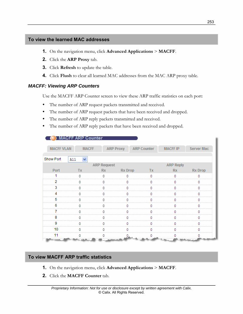
253
Proprietary Information: Not for use or disclosure except by written agreement with Calix. © Calix. All Rights Reserved.
To view the learned MAC addresses
1. On the navigation menu, click Advanced Applications > MACFF.
2. Click the ARP Proxy tab.
3. Click Refresh to update the table.
4. Click Flush to clear all learned MAC addresses from the MAC ARP proxy table.
MACFF: Viewing ARP Counters
Use the MACFF ARP Counter screen to view these ARP traffic statistics on each port:
The number of ARP request packets transmitted and received. The number of ARP request packets that have been received and dropped. The number of ARP reply packets transmitted and received. The number of ARP reply packets that have been received and dropped.
To view MACFF ARP traffic statistics
1. On the navigation menu, click Advanced Applications > MACFF.
2. Click the MACFF Counter tab.

254
Proprietary Information: Not for use or disclosure except by written agreement with Calix. © Calix. All Rights Reserved.
3. In the Show Port list, leave the selection at All to view statistics for all ports, or select a port for which to list statistics.
4. To update the statistics, at the bottom of the screen, click Refresh.
5. To reset all counters to zero, at the bottom of the screen, click Clear.
MACFF: Configuring a Static IP Address for a Subscriber Port
Use the MACFF IP screen to add a static IP address and subnet mask to the MACFF table for a specific port.
To configure a static IP address for a subscriber port
1. On the navigation menu, click Advanced Applications > MACFF.
2. Click the MACFF IP tab, and then do the following:
Note: Clicking Cancel before clicking Apply resets the screen parameter values.
a. In the Port list, select the subscriber port.
b. In the VID box, type the MACFF VLAN ID.
c. In the IP box, type the IP address in dotted decimal notation.
d. In the Subnet Mask box (from 24 to 32).
e. Below the Subnet Mask box, click Apply.
To delete a static IP address
1. On the navigation menu, click Advanced Applications > MACFF.
2. Click the MACFF IP tab.

255
Proprietary Information: Not for use or disclosure except by written agreement with Calix. © Calix. All Rights Reserved.
3. In the IP address list at the bottom of the page, under the Select column, select the check box(es) to the right of the IP address(es) you are deleting.
4. At the bottom of the page, click Delete.
MACFF: Creating a Trusted MAC for CFM Tests
Use the MACFF Server MAC screen to create a list of trusted MAC addresses for CFM testing when there is no application router (AR) IP address for MACFF.
To create a trusted MAC address
1. On the navigation menu, click Advanced Applications > MACFF.
2. Click the Server MAC tab.
3. In the Add MACFF VLAN box, type the MACFF VLAN ID.
Note: MACFF must be enabled for the VLAN. See Enabling MACFF VLANs (on page 249).
4. Below the MAC boxes, click Apply.
To delete a trusted MAC address
1. On the navigation menu, click Advanced Applications > MACFF.
2. Click the Server MAC tab.
3. In the MAC list at the bottom of the page, under the Select column, select the check box(es) to the right of the MAC address(es) you are deleting.
4. At the bottom of the page, click Delete.

256
Proprietary Information: Not for use or disclosure except by written agreement with Calix. © Calix. All Rights Reserved.
DHCP Snooping
This topic describes how to activate (or deactivate) DHCP snooping on each port.
DHCP snooping prevents clients from assigning their own IP addresses. The E3-12C/E5-120/E5-121 can store every address (xDSL port, MAC address, IP address) offered by the DHCP server. Then, it only forwards packets from clients whose MAC address and IP address are recorded. Packets from unknown IP addresses are dropped.
Calix recommends setting up DHCP snooping in these circumstances:
When MAC Forced-Forwarding (MACFF) is enabled. For a port uses DHCP. For a port that has three or fewer static IP addresses.
On the DHCP screen you can set the maximum number of dynamically-learned DHCP hosts (from 1 to 12), as well as the method for determining how to handle new DHCP leases when the maximum number of leases is reached. .
To set the DHCP snoop maximum count mode
1. On the navigation menu, click Advanced Applications > DHCP Snoop.
2. Click the DHCP Snoop tab.

257
Proprietary Information: Not for use or disclosure except by written agreement with Calix. © Calix. All Rights Reserved.
3. In the DHCP Snoop Maximum Count Mode list, select one of two options:
0 – When the maximum count is reached, the oldest DHCP lease in the DHCP snooping table is replaced with a new DHCP lease.
1 – When the maximum count is reached, no new DHCP lease is permitted until one of the leases in the DHCP snooping table expires.
4. To the right of the list, click Apply.
To define DHCP snoop settings
1. On the navigation menu, click Advanced Applications > DHCP Snoop.
2. Click the DHCP Snoop tab, and then do the following:
Note: Clicking Cancel before clicking Apply resets the parameters to the previously-saved values.
a. In the Port list, select a port.
b. Select the Active check box to enable DHCP snooping.
c. In the three Static IP boxes, enter up to three static IP addresses for which the E3-12C/E5-120/E5-121 should forward packets, even if the IP address is not assigned by the DHCP server. The E3-12C/E5-120/E5-121 drops packets from other unknown static IP addresses on this port.
These fields are only effective when DHCP snooping is active.
d. In the DHCP Snoop Max Count box, type the maximum number of DHCP hosts allowed for the port (1 to 12).
e. In the DHCP Source MAC Verify list, select Enable to activate source MAC verification on the specified port.
3. Click Add or Apply to save your changes to the system volatile memory.
4. (Recommended) On the navigation menu, use the Config Save option to save changes to non-volatile memory.
The port list at the bottom of the screen displays whether DHCP snooping is active ("V") or inactive ("-") for each port, along with the IP addresses for which the E3-12C/E5-120/E5-121 should forward packets. "0.0.0.0" indicates a blank value.
To modify DHCP snoop settings
1. On the navigation menu, click Advanced Applications > DHCP Snoop.
2. Click the DHCP Snoop tab.
3. In the port list, under the Port column, click the link for the port number of the DHCP snooping settings to edit.
The port settings display in the top half of the screen.

258
Proprietary Information: Not for use or disclosure except by written agreement with Calix. © Calix. All Rights Reserved.
4. Edit the settings per site requirements.
To delete an existing static IP address, enter 0.0.0.0.
5. Under the settings, click Apply.
DHCP Snoop Status Tab
Use this screen to view or clear the DHCP snooping table on each port.
To open the DHCP Snoop Status tab
1. On the navigation menu, click Advanced Applications > DHCP Snoop.
2. Click the DHCP Snoop Status tab.
3. Click the hyperlink on the port number to view the DHCP Host Route Table of that port.
The following table describes the elements of the DHCP Snoop Status tab:
Label Description
DHCP Snoop Click the DHCP Snoop tab to activate or deactivate DHCP snooping on each port.
DHCP Counter
Click the DHCP Counter tab to view a summary of the DHCP packets on each port.
Show Port Select a port to view information, or select ALL to list all ports.
Port The selected xDSL port number(s) display. Click on the port number to view the DHCP Host Route Table for that port.
Overflow The DHCP server can assign up to 32 IP addresses at one time to each port. This field displays the number of requests from DHCP clients above this limit.
IP The IP address assigned to a client on this port.
Gateway The IP address assigned to the network gateway.
MAC The MAC address of a client on this port to which the DHCP server assigned an IP address.

259
Proprietary Information: Not for use or disclosure except by written agreement with Calix. © Calix. All Rights Reserved.
Label Description
VID The VLAN ID, if any, on the DHCP Request packet.
Flush To remove all of entries from the DHCP snooping table for a port, select the target port in the Show Port list, and then click Flush.
DHCP Counter Tab
Use this screen to view a summary of the DHCP packets on specific ports.
To open the DHCP Counter tab
1. On the navigation menu, click Advanced Applications > DHCP Snoop.
2. Click the DHCP Counter tab.
The following table describes the elements of the DHCP Counter tab:
Label Description
DHCP Snoop Click the DHCP Snoop tab to activate or deactivate DHCP snooping on each port.
DHCP Snoop Status
Click the DHCP Snoop Status tab to view or clear the current DHCP snooping table on each port.
Show Port Select a port number to view information for a specific port or select All to view all ports.
Port The selected xDSL port number(s).
Discover The number of DHCP Discover packets on this port.
Offer This field displays the number of DHCP Offer packets on this port.
Request The number of DHCP Request packets on this port.
Ack The number of DHCP Acknowledge packets on this port.

260
Proprietary Information: Not for use or disclosure except by written agreement with Calix. © Calix. All Rights Reserved.
Label Description
Overflow The DHCP server can assign up to 32 IP addresses at one time to each port. This field displays the number of requests from DHCP clients above this limit.
Clear Click Clear to delete the information the E3-12C/E5-120/E5-121 has learned about DHCP packets. This resets every counter in this screen.

261
Proprietary Information: Not for use or disclosure except by written agreement with Calix. © Calix. All Rights Reserved.
Downstream and Upstream Broadcast
Downstream broadcast allows you to block downstream broadcast packets from being sent to specific VLANs on specific ports.
Upstream broadcast allows you to define the maximum data transmission rate for upstream broadcast traffic allowed to pass through the E3-12C/E5-120/E5-121. This helps to reduce the incoming broadcast packets and system load.
Upstream and downstream broadcast characteristics
Once upstream broadcast is enabled, it is applied to all of the subscriber ports; downstream broadcast is enabled as per VLAN per Port.
You can specify bandwidth for upstream broadcast traffic, but for the downstream broadcast traffic, you can block all downstream broadcast traffic (all ports) or specific ports on a per-port basis. For example, you specify the DSL port number that will have downstream broadcast traffic (on a specific VLAN) blocked.
Downstream Broadcast Screen
Use the Downstream Broadcast screen to block downstream broadcast packets from being sent to specified VLANs on specified ports.
To open the Downstream Broadcast screen
On the navigation menu, click Advanced Applications > Downstream Broadcast.
The following table describes the elements of the Downstream Broadcast screen:
Element Description
Port Use the Port list box to select a port to configure settings.
VLAN Specify the number of a VLAN (on this entry’s port) to which you do not want to send broadcast traffic. The VLAN must already be configured in the system.

262
Proprietary Information: Not for use or disclosure except by written agreement with Calix. © Calix. All Rights Reserved.
Element Description
Add Click Add to save the settings to volatile memory.
Calix recommends periodically saving configuration changes to non-volatile memory using the Config Save option on the navigation menu.
Blocking Table
Port Use the Port list box to select a port to display settings.
Index The number of the downstream broadcast blocking entry.
Port The number of a DSL port through which you will block downstream broadcast traffic (on a specific VLAN).
VLAN The number of a VLAN to which you do not want to send broadcast traffic (on the entry’s port).
Select Select an entry’s Select check box and click Delete to remove the entry.
Clicking Delete saves your changes to the E3-12C/E5-120/E5-121’s volatile memory.
Calix recommends periodically saving configuration changes to non-volatile memory using the Config Save option on the navigation menu.
Select All Click All to select all of the check boxes.
Select None Click None to clear all of the check boxes.
Upstream Broadcast Screen
Use the Upstream Broadcast screen to reduce the incoming broadcast packets and system load by defining the maximum data transmission for upstream broadcast traffic permitted to flow through the E3-12C/E5-120/E5-121.
To open the Upstream Broadcast screen
On the navigation menu, click Advanced Applications > Upstream Broadcast.

263
Proprietary Information: Not for use or disclosure except by written agreement with Calix. © Calix. All Rights Reserved.
The following table describes the elements of the Upstream Broadcast screen:
Element Description
Enable Select the Enable check box to enable bandwidth control for upstream broadcast traffic.
Rate Limit Enter the maximum bandwidth (from 32 to 65472 Kbps, in 32-Kpbs increments) for upstream broadcast traffic allowed to flow into the E3-12C/E5-120/E5-121.
Apply Click Apply to save the settings to the system volatile memory.
Calix recommends periodically saving configuration changes to non-volatile memory using the Config Save option on the navigation menu.
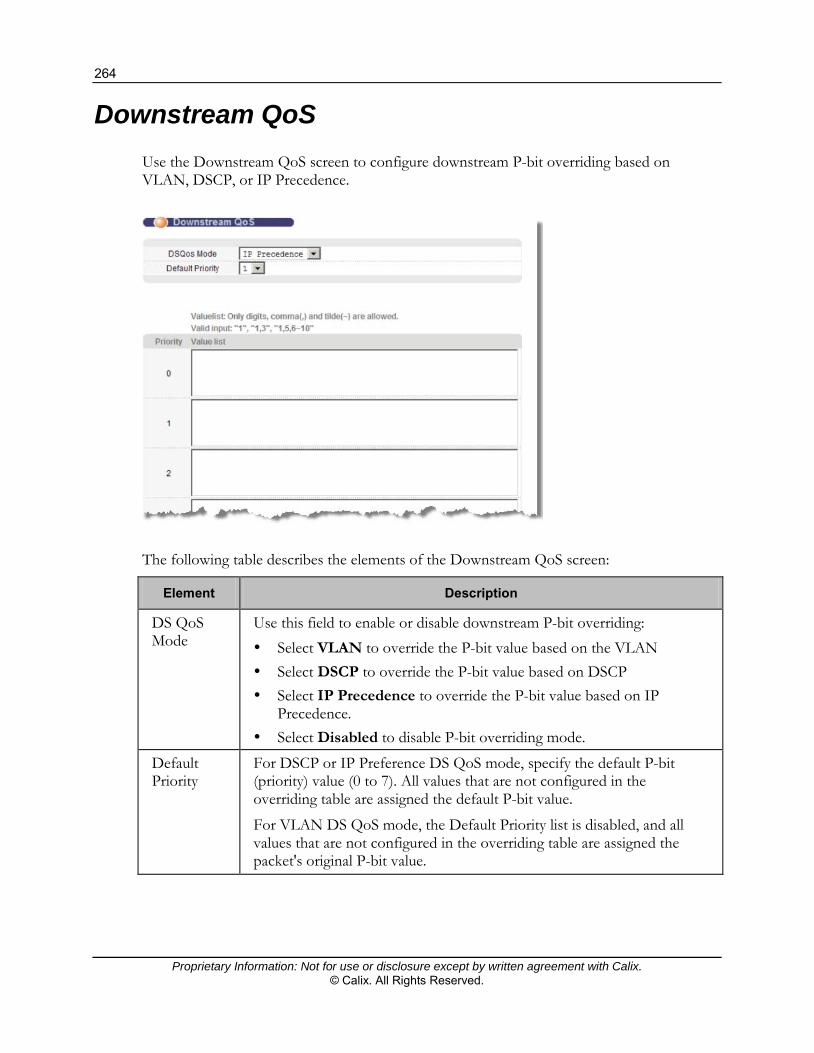
264
Proprietary Information: Not for use or disclosure except by written agreement with Calix. © Calix. All Rights Reserved.
Downstream QoS
Use the Downstream QoS screen to configure downstream P-bit overriding based on VLAN, DSCP, or IP Precedence.
The following table describes the elements of the Downstream QoS screen:
Element Description
DS QoS Mode
Use this field to enable or disable downstream P-bit overriding: Select VLAN to override the P-bit value based on the VLAN Select DSCP to override the P-bit value based on DSCP Select IP Precedence to override the P-bit value based on IP
Precedence. Select Disabled to disable P-bit overriding mode.
Default Priority
For DSCP or IP Preference DS QoS mode, specify the default P-bit (priority) value (0 to 7). All values that are not configured in the overriding table are assigned the default P-bit value.
For VLAN DS QoS mode, the Default Priority list is disabled, and all values that are not configured in the overriding table are assigned the packet's original P-bit value.

265
Proprietary Information: Not for use or disclosure except by written agreement with Calix. © Calix. All Rights Reserved.
Element Description
Value list For each P-bit (priority), add the values to include in the downstream QoS overriding.
Depending on the DS QoS mode, specify the VLAN IDs (1 to 4094), DSCP codes (1 to 63), or IP Precedence values (0 to 7).
Use a comma (without a trailing space) to separate individual entries or entry ranges, and a tilda to indicate a range of values.
Value list examples: <1>, <1,3>, <1,5,6~10>
Apply Click Apply to save the settings to the system volatile memory.
Calix recommends periodically saving configuration changes to non-volatile memory using the Config Save option on the navigation menu.
Cancel Click Cancel to restart configuring the P-bit overriding mode.
MTU Size
Use the MTU screen to configure the Maximum Transmission Unit (MTU) size for the Ethernet interfaces. The Ethernet interfaces discard any packets larger than the MTU size. The configurable size range is 1526 to 1532 bytes.
Configuring the MTU size
1. On the navigation menu, click Advanced Applications > MTU Size.
2. Enter the size, in bytes, of the Maximum Transmission Unit for the Ethernet interfaces.
3. Click Apply Settings to save the settings to volatile memory.
Calix recommends periodically saving configuration changes to non-volatile memory using the Config Save option on the navigation menu.

266
Proprietary Information: Not for use or disclosure except by written agreement with Calix. © Calix. All Rights Reserved.
Packet Filter
Use the Packet Filter screen to filter out specific types of packets on individual subscriber ports.
By default, all packet types are allowed, and the PPPoE Only check box is cleared (not selected).
To set packet filters
1. On the navigation menu, click Advanced Applications > Packet Filter.
2. In the Port list, select an xDSL port.
Note: Clicking Cancel resets the screen parameters to the last-saved settings.
3. Do one of the following:
Select the PPPoE Only check box to allow only Point-to-Point Protocol over Ethernet (PPPoE) traffic. Selecting this check box disables the check boxes for other packet types and the system drops any non-PPPoE packets for the specified port.
Select one or more of the following packet types:
PPPoE: Point-to-Point Protocol over Ethernet.
IP: Internet Protocol for routing packets on the Internet and other TCP/IP-based networks.
ARP: Address Resolution Protocol maps an Internet Protocol address (IP address) to a physical computer address that is recognized in the local network.

267
Proprietary Information: Not for use or disclosure except by written agreement with Calix. © Calix. All Rights Reserved.
NetBios: Network Basic Input/Output System are TCP or UDP packets that enable a computer to find other computers.
DHCP: Dynamic Host Configuration Protocol. EAPOL: Extensible Authentication Protocol (EAP, RFC 2486) over the
network. EAP is used with IEEE 802.1x to allow additional authentication methods (besides RADIUS) to be deployed with no changes to the access point or the wireless clients.
IGMP: Internet Group Management Protocol (IGMP) for sending packets to a specific group of hosts.
4. Click Add or Apply to save the settings to volatile memory.
Calix recommends periodically saving configuration changes to non-volatile memory using the Config Save option on the navigation menu.
Packet filter settings display in columns in the table at the bottom of the screen for each subscriber port:
"A" indicates that the packet types is accepted on the port.
"D" indicates that the packet types is discarded on the port.
When the PPPoE Only check box is selected, "#" indicates that all packet types except PPPoE are discarded (packet types not listed are also discarded).
To copy packet filter settings from one port to other ports
1. In the Copy Port list, select the port from which to copy settings.
2. Click Paste to open the port selection screen. Select the ports to which to copy the settings. (Click All to select every port, or None to clear the check boxes.)
3. Click Apply to copy the settings to the selected ports.
To edit packet filter settings for a port
1. On the navigation menu, click Advanced Applications > Packet Filter.
2. In the table at the bottom of the screen select a link for the xDSL port you are editing.
The settings for the port display in the top half of the screen, and the Port list displays the selected port.
Note: Clicking Cancel resets the screen parameters to the last-saved settings.
3. Make changes to the settings, as required.
4. Click Apply to save the settings to the system volatile memory.
Calix recommends periodically saving configuration changes to non-volatile memory using the Config Save option on the navigation menu.

268
Proprietary Information: Not for use or disclosure except by written agreement with Calix. © Calix. All Rights Reserved.
Upstream Limit
Use Upstream Limit screen to limit the transmission rate for upstream traffic per port.
To open the Upstream Limit screen
On the navigation menu, click Advanced Applications > Upstream Limit.
The following table describes the labels in the Upstream Limit screen:
Label Description
Enable Select this check box to enable/set the upstream limit for the specified port. Clear this check box if there is no limit.
Rate Enter the maximum upstream transmission rate (from 64 to 65472 Kbps). This field has no effect unless the Enable check box is selected.
Port Select the VDSL port for configuring the maximum upstream transmission rate.
Apply Click Apply to save the settings to the system volatile memory.
Calix recommends periodically saving configuration changes to non-volatile memory using the Config Save option on the navigation menu.
Cancel Click Cancel to clear the entries and re-begin configuring.

269
Proprietary Information: Not for use or disclosure except by written agreement with Calix. © Calix. All Rights Reserved.
Label Description
Show Port Click All to display all 24 VDSL ports or select a particular port from the list to display.
Select Check Boxes
You can select one or more check boxes from the Select column. Click Enable to enable the upstream rate limit for the selected ports.
To deactivate the upstream transmission rate limit, select one or more check boxes from the Select column and click Disable.
Select All Click All to select all of the check boxes.
Select None Click None to clear all of the check boxes.
MAC Filter
Use the MAC filter to control from which Media Access Control (MAC) addresses frames can (or cannot) come in through a port.
MAC Filter Screen
Use this screen to view and provision MAC filtering on the E3-12C/E5-120/E5-121.
To open the MAC Filter screen
On the navigation menu, click Advanced Applications > MAC Filter.

270
Proprietary Information: Not for use or disclosure except by written agreement with Calix. © Calix. All Rights Reserved.
The following table describes the elements of the MAC Filter screen:
Element Description
Port Use the Port list box to select an xDSL port to configure MAC filtering.
MAC Type a device’s MAC address in hexadecimal notation (xx:xx:xx:xx:xx:xx, where x is a number from 0 to 9 or a letter from a to f) in this field. The MAC address must be a valid MAC address.
Add Click Add to save the settings to volatile memory.
Calix recommends periodically saving configuration changes to non-volatile memory using the Config Save option on the navigation menu.
Cancel Click Cancel to start configuring the screen again.
Port The numbers of the xDSL ports.
Mode Select Accept to only allow frames from MAC addresses that you specify and block frames from other MAC addresses.
Select Deny to block frames from MAC addresses that you specify and allow frames from other MAC addresses.
Active Select the Active check box to turn on MAC filtering for a port.
MAC The MAC addresses that are set for this port.
Delete Click Delete to remove a MAC address from the list.
Apply Click Apply to save the settings to the system volatile memory.
Calix recommends periodically saving configuration changes to non-volatile memory using the Config Save option on the navigation menu.
OUI Filter
This section describes how to configure filter rules to block or forward packets, on a per-port basis, from devices based on the Organizational Unique Identifier (OUI).
The OUI is the first 3 octets of MAC addresses assigned to specific vendors by the IANA.
OUI Filter Screen
Use the OUI Filter screen to configure, on a per-port basis, the specific network devices the switch accepts traffic from or sends traffic to.
OUI filters block or forward packets from devices with the specified OUI in the MAC address.

271
Proprietary Information: Not for use or disclosure except by written agreement with Calix. © Calix. All Rights Reserved.
To configure an OUI filter
1. On the navigation menu, click Advanced Applications > OUI Filter.
Note: Clicking Cancel before clicking Add resets the OUI field.
2. In the Port list, select the port for which you are configuring an OUI filter.
3. In the OUI boxes, type the OUI for the STB or PC (for example, 00:02:61).
4. Click Add to associate the OUI with the port.
The first three octets of a MAC address display in the OUI column in the format xx:xx:xx.
5. In the port list at the bottom of the screen, in the Mode list, specify the action on matched frames:
Select Accept to allow frames with a matched OUI. The switch blocks frames with other OUIs not specified.
Select Deny to block frames with a matched OUI. The switch allows frames with other OUIs not specified.
6. Select the Active check box to enable the filter. (Clearing the check box disables the filter without deleting it.)
7. Click Apply to save the settings to volatile memory.
Calix recommends periodically saving configuration changes to non-volatile memory using the Config Save option on the navigation menu.
To delete an OUI filter
1. On the navigation menu, click Advanced Applications > OUI Filter.
2. In the port list at the bottom of the screen, click Delete in the port row to remove the OUI filter from the port.

272
Proprietary Information: Not for use or disclosure except by written agreement with Calix. © Calix. All Rights Reserved.
To copy an OUI filter from one port to other ports
1. On the navigation menu, click Advanced Applications > OUI Filter.
2. At the bottom of the screen, in the Copy Port list, select the port to copy from. Click Paste.
3. In the popup dialog box, select the check boxes next to the port(s) to copy the settings to. (Click All select all ports; clicking None clears all check boxes.)
4. Click Apply to save the settings to volatile memory.
Calix recommends periodically saving configuration changes to non-volatile memory using the Config Save option on the navigation menu.
N1MAC
Use the N1MAC screen to enable multiple-to-one MAC address conversion for a port.
To configure the N1MAC
1. On the navigation menu, click Advanced Applications > N1MAC.
The E3-12C/E5-120/E5-121’s MAC address used to replace MAC addresses of subscriber DSL modems in upstream packets.
2. Under the Active column, select the check boxes of the port for which you are enabling N1MAC (clicking All selects all check boxes; clicking None clears all check boxes.)
3. Click Add or Apply to save the settings to volatile memory.
Calix recommends periodically saving configuration changes to non-volatile memory using the Config Save option on the navigation menu.

273
Proprietary Information: Not for use or disclosure except by written agreement with Calix. © Calix. All Rights Reserved.
Viewing N1MAC Status
Use the N1MAC status tab to display multiple-to-one MAC (N1MAC) mapping table.
To view the N1MAC status
1. On the navigation menu, click Advanced Applications > N1MAC.
2. Click the N1MAC Status tab.
3. In the Show Port list, select a port, or select All, to display the available multiple-to-one MAC mapping table for the port(s).
The following information displays in the xDSL port list at the bottom of the screen:
Type: "pppoaoe" displays when the connected subscriber uses PPPoE or PPPoA for the xDSL connection. "ipoa" or "ipoe" displays when the subscriber uses IPoA or IPoE for the connection.
PPP Session ID / IP: A PPP session identifier (when using PPPoA or PPPoE) or an IP address (when using IPoA or IPoE) that the E3-12C/E5-120/E5-121 uses to recognize the original subscriber’s MAC address. The E3-12C/E5-120/E5-121 puts the subscriber’s MAC address back into traffic returned from the uplink network.
MAC: A MAC address that has been replaced with the E3-12C/E5-120/E5-121’s MAC address in upstream frames.
Clicking Clear removes all entries.

274
Proprietary Information: Not for use or disclosure except by written agreement with Calix. © Calix. All Rights Reserved.
2684 Routed Mode
Use the RFC 2684 (formerly 1483) routed mode to configure the E3-12C/E5-120/E5-121 to add MAC address headers to 2684 routed mode traffic from a Permanent Virtual Channel (PVC) that connects to a subscriber device using 2684 routed mode. You also specify the gateway to which the E3-12C/E5-120/E5-121 sends the traffic and the VLAN ID tag to add. See RFC-2684 for details on routed mode traffic carried over AAL type 5 over ATM.
Use the Routed PVC tab to configure PVCs for 2684 routed mode traffic. Use the Routed Domain tab to configure domains for 2684 routed mode traffic. The
domain is the range of IP addresses behind the subscriber’s device (the CPE or Customer Premises Equipment). This includes the CPE device’s network IP addresses and the IP addresses of the network computers.
Use the RPVC ARP Proxy tab to view the Address Resolution Protocol table of IP addresses of CPE devices using 2684 routed mode and configure how long the device is to store them.
Use the Routed Gateway tab to configure gateway settings.
For upstream traffic: Since the subscriber device does send out a MAC address, after the E3-12C/E5-120/E5-121 reassembles the Ethernet packets from the AAL5 ATM cells, the E3-12C/E5-120/E5-121 appends the routed mode gateway MAC address and the E3-12C/E5-120/E5-121 MAC address as the destination/source MAC address.
For downstream traffic: When the E3-12C/E5-120/E5-121 detects that the destination IP address is specified in the RPVC (or RPVC domain), the E3-12C/E5-120/E5-121 strips out the MAC header and send traffic to the corresponding RPVC.
2684 Routed Mode Example
The graphic below shows a sample 2684 routed mode configuration. The gateway server uses IP address 192.168.10.102 and is in VLAN 1. The E3-12C/E5-120/E5-121 uses IP address 192.168.20.101. The subscriber device (CPE) connects to DSL port 1 on the E3-12C/E5-120/E5-121 and the 2684 routed mode traffic uses the PVC identified by VPI 8 and VCI 35.
The CPE device WAN IP address is 192.168.10.200. The routed domain is the network IP addresses behind the CPE device. The CPE device network IP address is 10.10.10.10. The network computer IP address is 10.10.10.1. This includes the CPE device network IP addresses and the IP addresses of the network computers.

275
Proprietary Information: Not for use or disclosure except by written agreement with Calix. © Calix. All Rights Reserved.
IP: 192.168.10.102VLAN 1
IP: 192.168.20.101
PVC 8/35
IP: 192.168.10.200
IP: 10.10.10.10IP: 10.10.10.1
Note the following:
The CPE device WAN IP address (192.168.10.200 in this example) must be in the same subnet as the gateway IP address (192.168.10.102 in this example).
The E3-12C/E5-120/E5-121 management IP address can be any IP address. It has no relationship to the WAN IP address or routed gateway IP address.
The E3-12C/E5-120/E5-121 management IP address should not be in the same subnet as the one defined by the WAN IP address and netmask of the subscriber’s device.
Note: Calix recommends that you set the netmask of the subscriber WAN IP address to 32 to avoid this problem.
The E3-12C/E5-120/E5-121 management IP address should not be in the same subnet range of any RPVC and RPVC domain.
The E3-12C/E5-120/E5-121 management IP address should not be in the same subnet as the one defined by the network IP address and netmask of the CPE. Make sure you assign the IP addresses properly.
In a typical deployment, the computer sets the CPE device network IP address (10.10.10.10 in this example) as its default gateway.
The subnet range of any RPVC and RPVC domain must be unique.

276
Proprietary Information: Not for use or disclosure except by written agreement with Calix. © Calix. All Rights Reserved.
Routed PVC Tab
Use this screen to configure PVCs for 2684 routed mode traffic.
To open the Routed PVC tab
1. On the navigation menu, click Advanced Applications > 2684 Routed Mode.
2. Click the Routed PVC tab.
The following table describes the elements of the 2684 Routed PVC tab:
Element Description
Routed Domain tab
Click the Routed Domain tab to configure domains for 2684 routed mode traffic.
RPVC ARP Proxy tab
Click the RPVC ARP Proxy tab to view the Address Resolution Protocol table of IP addresses of CPE devices using 2684 routed mode and configure how long the device is to store them.
Routed Gateway tab
Click the Routed Gateway tab to configure gateway settings.
Port Use the Port list box to select a port to configure settings.
Gateway IP Enter the IP address of the gateway to which you want to send the traffic that the system receives from this PVC. Enter the IP address in dotted decimal notation.
VPI Type the Virtual Path Identifier for this routed PVC.
VCI Type the Virtual Circuit Identifier for this routed PVC.
IP Enter the subscriber’s CPE WAN IP address in dotted decimal notation.

277
Proprietary Information: Not for use or disclosure except by written agreement with Calix. © Calix. All Rights Reserved.
Element Description
NetMask The bit number of the subnet mask of the subscriber’s WAN IP address. To find the bit number, convert the subnet mask to binary and add all of the 1s together. Take “255.255.255.0” for example. 255 converts to eight 1s in binary. There are three 255s, so add three eights together and you get the bit number (24).
Make sure that the routed PVC’s subnet does not include the E3-12C/E5-120/E5-121 IP address.
Note: Because the E3-12C/E5-120/E5-121 supports up to 16 subscriber WAN IP addresses per port in RPVC applications, you have to specify the netmask at no less than 28 (29, 30, 31 and 32 are also acceptable).
IP QoS Profile Select an IP QoS profile to classify and prioritize application traffic flowing through this PVC. See Creating IP QoS Profiles (on page 74).
Encap Select an encapsulation method (llc or vc) for this PVC.
Add Click Apply to save the settings to the system volatile memory.
Calix recommends periodically saving configuration changes to non-volatile memory using the Config Save option on the navigation menu.
Cancel Click Cancel to start configuring the screen again.
Index The number of the routed PVC.
Port The number of the VDSL2 port on which the routed PVC is configured.
VPI The Virtual Path Identifier (VPI) The VPI and VCI identify a channel on this port.
VCI The Virtual Circuit Identifier (VCI). The VPI and VCI identify a channel on this port.
IP This field displays the subscriber’s IP address.
NetMask The bit number of the subnet mask of the subscriber’s IP address.
IP QoS Profile The IP QoS profile applied on this PVC.
Gateway IP The IP address of the gateway to which you want to send the traffic that the system receives from this PVC.

278
Proprietary Information: Not for use or disclosure except by written agreement with Calix. © Calix. All Rights Reserved.
Element Description
Delete check box
Delete button
Select an entry’s Delete check box and click Delete to remove the entry.
Clicking Delete saves your changes to the E3-12C/E5-120/ E5-121’s volatile memory. Calix recommends periodically saving configuration changes to non-volatile memory using the Config Save option on the navigation menu
Cancel Click Cancel to start configuring the screen again.
Routed Domain Tab
Use this screen to configure domains for 2684 routed mode traffic. The domain is the range of IP addresses behind the subscriber device (the CPE). This includes the CPE device network IP addresses and the IP addresses of the network computers.
To open the Routed Domain tab
1. On the navigation menu, click Advanced Applications > 2684 Routed Mode.
2. Click the Routed Domain tab.
The following table describes the elements of the 2684 Routed Domain tab:
Element Description
Port Use the Port list box to select a port to configure settings.
VPI Type the Virtual Path Identifier for this routed PVC.
VCI Type the Virtual Circuit Identifier for this routed PVC.
IP Enter the subscriber’s CPE network IP address in dotted decimal notation.

279
Proprietary Information: Not for use or disclosure except by written agreement with Calix. © Calix. All Rights Reserved.
Element Description
NetMask The bit number of the subnet mask of the subscriber’s IP address. To find the bit number, convert the subnet mask to binary and add all of the 1s together. Take “255.255.255.0” for example. 255 converts to eight 1s in binary. There are three 255s, so add three eights together and you get the bit number (24).
Add Click Add to save your changes to the E3-12C/E5-120/E5-121’s volatile memory.
The E3-12C/E5-120/E5-121 loses these changes if it is turned off or loses power. After you have completed provisioning, use the Config Save feature to save your changes. On the navigation menu, click Config Save to save your changes to the non-volatile memory.
Cancel Click Cancel to start configuring the screen again.
Index The number of the routed PVC.
Port The number of the xDSL port on which the routed PVC is configured.
VPI The Virtual Path Identifier (VPI) The VPI and VCI identify a channel on this port.
VCI The Virtual Circuit Identifier (VCI). The VPI and VCI identify a channel on this port.
IP The subscriber’s IP address.
NetMask The bit number of the subnet mask of the subscriber’s network IP address.
Delete check box
Delete button
Select an entry’s Delete check box and click Delete to remove the entry.
Clicking Delete saves your changes to the E3-12C/E5-120/E5-121’s volatile memory.
Calix recommends periodically saving configuration changes to non-volatile memory using the Config Save option on the navigation menu.
Cancel Click Cancel to start configuring the screen again.

280
Proprietary Information: Not for use or disclosure except by written agreement with Calix. © Calix. All Rights Reserved.
RPVC ARP Proxy Tab
Use this screen to view the Address Resolution Protocol table of IP addresses of CPE devices using 2684 routed mode and configure how long the device is to store them.
To open the RPVC ARP Proxy tab
1. On the navigation menu, click Advanced Applications > 2684 Routed Mode.
2. Click the RPVC ARP Proxy tab.
The following table describes the elements of the RPVC ARP Proxy tab:
Element Description
Aging Time Enter a number of seconds (10 through 10000) to set how long the device keeps the Address Resolution Protocol table’s entries of IP addresses of CPE devices using 2684 routed mode. Enter 0 to disable the aging time.
Apply Setting Click Apply to save the settings to the system volatile memory.
Calix recommends periodically saving configuration changes to non-volatile memory using the Config Save option on the navigation menu.
Index The number of the IP address entry.
Gateway IP The IP address of the gateway to which the device sends the traffic that it receives from this entry’s IP address.
VID The VLAN ID that the device adds to Ethernet frames that it sends to this gateway.
MAC The subscriber’s Media Access Control (MAC) address.
Flush Click Flush to remove all of the entries from the ARP table.

281
Proprietary Information: Not for use or disclosure except by written agreement with Calix. © Calix. All Rights Reserved.
Routed Gateway Tab
Use this screen to configure gateway settings.
To open the Routed Gateway tab
1. On the navigation menu, click Advanced Applications > 2684 Routed Mode.
2. Click the Routed Gateway tab.
The following table describes the elements of the 2684 Routed Gateway tab:
Element Description
Gateway IP Enter the IP address of the gateway to which you want to send the traffic that the system receives from this PVC. Enter the IP address in dotted decimal notation.
VID Specify a VLAN ID to add to Ethernet frames that the system routes to this gateway.
Priority Select the IEEE 802.1p priority (0 to 7) to add to the traffic that you send to this gateway.
Add Click Add to save your changes to the E3-12C/E5-120/E5-121’s volatile memory.
The E3-12C/E5-120/E5-121 loses these changes if it is turned off or loses power. After you have completed provisioning, use the Config Save feature to save your changes. On the navigation menu, click Config Save to save your changes to the non-volatile memory.
Index The number of the gateway entry.
Gateway IP The IP address of the gateway.
VID The VLAN ID that the system adds to Ethernet frames that it sends to this gateway.

282
Proprietary Information: Not for use or disclosure except by written agreement with Calix. © Calix. All Rights Reserved.
Element Description
Priority The IEEE 802.1p priority (0 to 7) that is added to traffic sent to this gateway.
Delete check box
Delete button
Select an entry’s Delete check box and click Delete to remove the entry.
Clicking Delete saves your changes to the E3-12C/E5-120/E5-121’s volatile memory.
Calix recommends periodically saving configuration changes to non-volatile memory using the Config Save option on the navigation menu.
Cancel Click Cancel to start configuring the screen again.

Proprietary Information: Not for use or disclosure except by written agreement with Calix. © Calix. All Rights Reserved.
Chapter 10
VLAN Management Features
This section covers the following topics:
Static VLANs Multicast VLANs VLAN translation Protocol VLANs

284
Proprietary Information: Not for use or disclosure except by written agreement with Calix. © Calix. All Rights Reserved.
Static VLANs
For static VLAN setup information, see the instructions under the applicable services model:
VLAN-per-Service (N:1) Data Model (on page 107) VLAN-per-Port (1:1) Data Model (on page 113) Transparent LAN Service (TLS Business Services) (on page 125) Configuring Residential Gateway Services (on page 138) Video and Data Support: xDSL Standard VLAN Model (on page 151) Video and Data Support: VDSL, Multicast VLAN Model (on page 157)
Viewing VLAN Statuses
Use the VLAN Status screen to view the VLAN status.
To open the VLAN Status tab
1. On the navigation menu, click Advanced Applications > VLAN.
2. Click the VLAN Status tab.

285
Proprietary Information: Not for use or disclosure except by written agreement with Calix. © Calix. All Rights Reserved.
The following table describes the elements of the VLAN Status tab:
Label Description
The Number of VLAN
The number of VLANs configured on the E3-12C/E5-120/E5-121.
Page x of x Identifies which page of VLAN status information is displayed and the total pages of VLAN status information.
The first table displays the names of the fields. The subsequent tables show the settings of the VLANs.
Index The VLAN index number.
Name / VID Identifies an individual VLAN. The VLAN ID (VID) is the Port VLAN ID (PVID) assigned to untagged frames or priority-tagged frames received on this port.
1 to 24, enet1, enet2 The VLAN settings for each port. A tagged port is marked as T, an untagged port is marked as U and ports not participating in a VLAN are marked as "–".
Elapsed Time Identifies how long it has been since a normal VLAN was registered or a static VLAN was set up.
Status Displays that this VLAN was added to the E3-12C/E5-120/E5-121 statically, that is, added as a permanent entry.
Poll Interval(s)
Set Interval
Identifies how often (in seconds) this screen refreshes. You may change the refresh interval by typing a new number in the text box and then clicking Set Interval.
Stop Click Stop to halt polling statistics.
Previous Page
Next Page
Click one of these buttons to show the preceding or following screen if the information cannot be displayed in one screen.

286
Proprietary Information: Not for use or disclosure except by written agreement with Calix. © Calix. All Rights Reserved.
Editing and Deleting Static VLANs
Use the VLAN Setup screen to configure basic settings and port members for a static VLAN.
To edit a static VLAN or make the VLAN inactive
1. On the navigation menu, click Advanced Applications > VLAN.
2. Click the Static VLAN Settings tab.
3. In the VLAN list at the top of the screen, click the VLAN ID link.
4. Per site requirements, modify the active status, VLAN name, control settings, or tagging settings.
5. Click Apply to save the settings to volatile memory.
Calix recommends periodically saving configuration changes to non-volatile memory using the Config Save option on the navigation menu.
To delete a VLAN
1. On the navigation menu, click Advanced Applications > VLAN.
2. Click the Static VLAN Settings tab.
3. In the VLAN list at the top of the screen, under the Delete column, select the check box for VLAN you are deleting.
4. Under the list, click Delete.

287
Proprietary Information: Not for use or disclosure except by written agreement with Calix. © Calix. All Rights Reserved.
Multicast VLANs
For MVLAN setup information, see the instructions under the applicable services model:
Residential Gateway Support (on page 138) xDSL Video and Data Support: Static VLAN Model (on page 151) VDSL Video and Data Support: Multicast VLAN Model (on page 157)
Viewing MVLAN Statuses
Use the MVLAN Status screen to view a summary of all multicast VLANs on the E3-12C/E5-120/E5-121.
To open the MVLAN Status tab
1. On the navigation menu, click Advanced Applications > Multicast VLAN.
2. Click the MVLAN Status tab.
The following table describes the elements of the MVLAN Status tab:
Label Description
The Number of MVLAN
The number of multicast VLAN configured on the E3-12C/E5-120/E5-121.
The first table displays the names of the fields. The subsequent tables show the settings for each multicast VLAN.
Index A sequential value and is not associated with this multicast VLAN.
Name / VID The name and VLAN ID of this multicast VLAN.
1 through xx Display whether or not each port is a member of this multicast VLAN. "V" displays for members and "-" displays

288
Proprietary Information: Not for use or disclosure except by written agreement with Calix. © Calix. All Rights Reserved.
Label Description
ENET1, 2 for non-members. You can change these settings in the MVLAN Setup screen.
Status Displays whether this multicast VLAN is active (Enable) or inactive (Disable).
Editing and Deleting MVLANs
Use the MVLAN Setup screen to configure basic settings and port members for a multicast VLAN.
To edit a multicast VLAN or make the VLAN inactive
1. On the navigation menu, click Advanced Applications > Multicast VLAN.
2. Click the MVLAN Setup tab.
3. In the multicast VLAN list at the top of the screen, click the VLAN ID link.
4. Per site requirements, modify the active status, multicast VLAN name, control settings, or tagging settings.
5. At the bottom of the screen, click Apply to save your changes to volatile memory.
Calix recommends periodically saving configuration changes to non-volatile memory using the Config Save option on the navigation menu.
To delete a multicast VLAN
1. On the navigation menu, click Advanced Applications > Multicast VLAN.
2. Click the MVLAN Setup tab.
3. In the multicast VLAN list at the top of the screen, under the Delete column, select the check box for multicast VLAN you are deleting.
4. Under the list, click Delete.
Editing and Deleting an MVLAN Group
Use the MVLAN Group screen to configure ranges of multicast IP addresses for a multicast VLAN.
To edit a multicast VLAN group
1. On the navigation menu, click Advanced Applications > Multicast VLAN.
2. Click the MVLAN Group tab.

289
Proprietary Information: Not for use or disclosure except by written agreement with Calix. © Calix. All Rights Reserved.
3. In the bottom of the screen, select the MVLAN ID to view the indexes currently assigned to it.
4. In the MVLAN list at the top of the screen, select the multicast VLAN ID, and then in the Index list, select the existing index number to edit, or a new index number to create another multicast IP address range.
5. Type the new start and end multicast IP addresses as required.
6. Below the End Multicast IP of the screen, click Apply to save your changes to volatile memory.
Calix recommends periodically saving configuration changes to non-volatile memory using the Config Save option on the navigation menu.
To delete a multicast VLAN group index
1. On the navigation menu, click Advanced Applications > Multicast VLAN.
2. Click the MVLAN Setup tab.
3. In the multicast VLAN list at the bottom of the screen, under the Select column, select the check box(es) for multicast VLAN(s) group index(es) you are deleting.
4. At the bottom of the screen, click Delete.
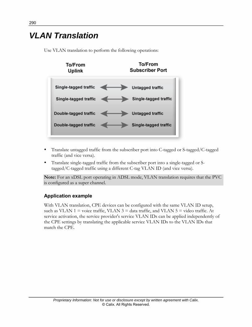
290
Proprietary Information: Not for use or disclosure except by written agreement with Calix. © Calix. All Rights Reserved.
VLAN Translation
Use VLAN translation to perform the following operations:
Translate untagged traffic from the subscriber port into C-tagged or S-tagged/C-tagged
traffic (and vice versa). Translate single-tagged traffic from the subscriber port into a single-tagged or S-
tagged/C-tagged traffic using a different C-tag VLAN ID (and vice versa).
Note: For an xDSL port operating in ADSL mode, VLAN translation requires that the PVC is configured as a super channel.
Application example
With VLAN translation, CPE devices can be configured with the same VLAN ID setup, such as VLAN 1 = voice traffic, VLAN 3 = data traffic, and VLAN 5 = video traffic. At service activation, the service provider's service VLAN IDs can be applied independently of the CPE settings by translating the applicable service VLAN IDs to the VLAN IDs that match the CPE.

291
Proprietary Information: Not for use or disclosure except by written agreement with Calix. © Calix. All Rights Reserved.
Creating VLAN Translation Rules
This topic describes how to create VLAN translation rules and add an ordered collection of matching rules to ports for associating with service tag actions. VLAN translation rules define how the E3-12C/E5-120/E5-121 classifies subscriber traffic to determine the service in which it belongs.
VLAN translation can:
contain both “tagged” and “untagged” rules. be applied either to upstream and downstream traffic or only to downstream traffic. be applied either to a VDSL port or a VPI/VCI channel (configured as a super channel)
on an ADSL port.
Important: VLAN translation parameter definitions for the E3-12C/E5-120/E5-121 differ from other Calix products. Be sure that you are familiar with them.
Parameter definitions for single-tagged traffic
The CXVID is the expected VLAN ID/tag received on the subscriber port (for tagged CPE traffic), or use zero (0) for untagged CPE traffic.
The CVID is the VLAN ID/tag that the CXVID will be translated into. Since there is only one tag, the CVID is the service provider's VLAN ID/tag.
The SVID is set to zero (0) to represent single-tagged traffic.
Parameter definitions for double-tagged traffic
The CXVID is the expected VLAN ID/tag received on the subscriber port (for tagged CPE traffic), or use zero (0) for untagged CPE traffic.
The CVID is the VLAN ID/tag that the CXVID will be translated into. Since there are two tags (outer tag and inner tag), the CVID is the inner VLAN ID/C-tag.
The SVID is the outer VLAN ID/S-tag.
Configuration guidelines
VLAN translation rules are applied to port traffic before PVIDs are assigned. Traffic from the subscriber that does not match a defined VLAN translation rule is still
forwarded upstream. Up to four VLAN translation rules can be created per port (VDSL) or super channel
PVC (ADSL). Each rule is configured as an entry in the VLAN Translation Table (VTT). Up to 16 combined VLANs, PVLANs, and VLAN translation rules can be assigned to
each port or super channel PVC.

292
Proprietary Information: Not for use or disclosure except by written agreement with Calix. © Calix. All Rights Reserved.
To set up a VLAN translation rule
1. On the navigation menu, click Advanced Applications > VLAN Translation.
Note: Clicking Cancel clears the screen of changes without saving them.
2. In the Port list, select an xDSL subscriber port through which to configure VLAN translation for transmitted traffic.
3. (For ADSL ports) Select the with vpi/vci check box to specify a VPI/VCI channel through which to configure VLAN translation.
When the with vpi/vci check box is selected, type the Virtual Path Identifier (VPI) and Virtual Circuit Identifier (VCI) to specify a channel on the port.
Note: The PVC must be configured as a super channel.
4. In the SVID box, type one of the following:
The VLAN ID (1 to 4094) to match the service provider's network.
Zero (0) to create a rule for single-tagged traffic.
5. In the CVID box, type the VLAN ID (1 to 4094) to apply for traffic forwarded to the service provider's network.
6. In the CXVID box, type one of the following:
The original customer VLAN ID (1 to 4094) to match for traffic received from the subscriber.
Zero (0) to match untagged traffic from the subscriber port.

293
Proprietary Information: Not for use or disclosure except by written agreement with Calix. © Calix. All Rights Reserved.
7. Do one of the following:
Select the Downstream only check box to only apply the VLAN translation rule for traffic sent from the E3-12C/E5-120/E5-121 to the subscriber.
Leave the check box clear (not selected) to apply the rule to both downstream and upstream traffic.
8. Click Add or Apply to save the settings to volatile memory.
9. Calix recommends periodically saving configuration changes to non-volatile memory using the Config Save option on the navigation menu.
In the bottom half of the screen, view the ports for which you have configured VLAN translation rules.
*/* displayed in the VPI and VCI columns indicates that the VLAN translation rules are applied to all channels on the port.
<-> in the Direction column indicates that VLAN translation is applied to both downstream and upstream traffic
-> indicates that VLAN translation is only applied to downstream traffic.
To delete a VLAN translation rule
1. In the VLAN translation rule list at the bottom of the VLAN Translation screen, in the Select column, select the check box(es) to the right of the row(s) to delete. (Clicking All selects all entries in the table; clicking None clears any selected entries.)
2. At the bottom of the screen, click Delete.

294
Proprietary Information: Not for use or disclosure except by written agreement with Calix. © Calix. All Rights Reserved.
Protocol VLAN
With protocol-based VLANs (PVLANs), an “802.1Q untagged” packet is tagged a VLAN ID based on its protocol. Enable this feature on a port to convert the VLAN untagged packets (sent from the connected CPE device) to VLAN-tagged packets which are then allowed to flow into a VLAN-tagged switch network for specified traffic. You can set different VLANs for different application traffic on a port. For example, you can define 0806 (ARP) and 0800 (IP) on a port. Then untagged ARP and IP traffic will be tagged with the specified VLAN IDs. The other untagged packets will be tagged with each port’s PVID VLAN depending on which port the packets flow through.
Protocol VLAN Screen
Use this screen to configure a VLAN tag to add to or remove from specific traffic flowing through a specified port.
To open the Protocol VLAN screen
On the navigation menu, click Advanced Applications > Protocol VLAN.
The following table describes the elements of the Protocol VLAN screen:
Element Description
Port Select the port to apply this protocol VLAN tag to for traffic flow.
VDSL Frame Mode
Select this for a VDSL port or clear this for an ADSL port.
VPI / VCI When the VDSL Frame Mode check box is cleared, type the Virtual Path Identifier and Virtual Circuit Identifier for the VC.
VID Specify a VLAN ID (1 to 4094).

295
Proprietary Information: Not for use or disclosure except by written agreement with Calix. © Calix. All Rights Reserved.
Element Description
Ether Type Enter four digits in hexadecimal for the Ethernet type that specifies the protocol of the traffic. For example, 0806 is the Ethernet type, 0x0806, for ARP (Address Resolution Protocol) traffic.
Priority Enter the priority level for the protocol VLAN. "0" is the lowest priority level and "7" is the highest level.
Add Click Add to save the settings to volatile memory.
Calix recommends periodically saving configuration changes to non-volatile memory using the Config Save option on the navigation menu.
Cancel Click Cancel to begin configuring the screen again.
The table in the bottom half of the screen displays the VLANs that specific untagged traffic belongs to.
Index The index number of records in the table.
Port The port number for the specified VC.
VPI The Virtual Path Identifier for the specified VC.
VCI The Virtual Circuit Identifier for the specified VC.
VID A VLAN (VLAN ID) that specific traffic will be assigned.
Ether Type Ethernet types to specify a particular protocol traffic. (See Ether Type above.)
Priority The priority for the protocol VLAN.
Select
Delete
Select the radio button of a VLAN membership entry and then click Delete to remove an entry.

296
Proprietary Information: Not for use or disclosure except by written agreement with Calix. © Calix. All Rights Reserved.
Proprietary Information: Not for use or disclosure except by written agreement with Calix. © Calix. All Rights Reserved.
Chapter 11
Security Features
This section covers the following topics:
Denial of Service (DoS) security features Port authentication Port security Access control
298
Proprietary Information: Not for use or disclosure except by written agreement with Calix. © Calix. All Rights Reserved.
Denial of Service (DoS) Security Features
The E3-12C/E5-120/E5-121 supports following DoS features that protect against DoS attacks:
IGMP query protocol messages processed on subscriber (xDSL) ports are discarded. A log event is generated for each discarded message.
When DHCP snooping is enabled, unexpected DHCP messages (such as DHCPOFFER, DHCPACK, and DHCPNAK) that originated from a non-trusted source are dropped. A log event is generated for each dropped message.
Any DHCP Request or Discover packet with a nonzero "giaddr" are dropped. Any server-side DHCP packet for which the client address does not match the
destination MAC are dropped. Any DHCP message for which the client identifier is excluded from the binding table on
the corresponding interface (messages that the client initiates after being provided an IP address, such as Release) are dropped.
The DHCP relay function is applied to CPEs connected to the E3-12C/E5-120/E5-121. A configuration option (CLI only) for enabling source MAC verification on a per-port
basis: switch dhcpsnoop smacverify
For information about the command, see the Calix E3-12C/E5-120/E5-121 CLI Reference.
A configuration option (CLI only) for verifying the source IP with DHCP snooping on a per-port basis:
switch dhcpsnoop pool
When enabled, the E3-12C/E5-120/E5-121 drops all packets with a different source IP address than the DHCP-learned IP address.
For information about the command, see the Calix E3-12C/E5-120/E5-121 CLI Reference.
A configuration option for limiting DHCP leases on a per-port basis. When enabled, a limit of up to 12 DHCP leases can be applied per port. When the limit is reached, new DHCP requests are handled in one of these user-configurable methods: 1) a new lease is dropped from the port until one of the leases expires; or 2) a new lease replaces the oldest DHCP lease. For more information, see Setting Up DHCP Snooping (on page 256).

299
Proprietary Information: Not for use or disclosure except by written agreement with Calix. © Calix. All Rights Reserved.
A configuration option (CLI only) that controls the behavior of the switch when MAC collision is detected:
switch mac antispoofing policy
The disable-port action prevents an offending port from generating traffic. This DHCP feature also applies to MAC collisions outside the scope of DHCP snoop-enabled VLANs. A log event and trap are generated for a duplicate MAC condition regardless of the MAC antispoofing policy you have set.
For information about the command, see the Calix E3-12C/E5-120/E5-121 CLI Reference.
If the MAC address permanently moves, the E3-12C/E5-120/E5-121 switches traffic from one port to another. This permits legitimate instances of moving a MAC address resulting from, for example, a service technician moving from house to house or a subscriber visiting a neighbor with a laptop.
Port Authentication
IEEE 802.1x is an extended authentication protocol that enables support of Remote Authentication Dial In User Service (RADIUS) RFC 2138, 2139 for centralized user profile management on a network RADIUS server.
RADIUS
Remote Authentication Dial In User Service (RADIUS) authentication is a popular protocol used to authenticate users by means of an external server instead of (or in addition to) an internal device user database that is limited to the memory capacity of the device. In essence, RADIUS authentication allows you to validate an unlimited number of users from a central location.
Local user database
Storing user profiles locally on the E3-12C/E5-120/E5-121 enables you to authenticate users programmatically.

300
Proprietary Information: Not for use or disclosure except by written agreement with Calix. © Calix. All Rights Reserved.
RADIUS Tab
Use the RADIUS tab to enable or disable an external RADIUS server to authenticate users or you can enable or disable an internal database of user names and passwords to authenticate users.
To open the RADIUS tab
1. On the navigation menu, click Advanced Applications > Port Authentication.
2. Click the RADIUS tab.
The following table describes the elements of the RADIUS tab:
Label Description
802.1x tab Click the 802.1x tab to configure individual port authentication settings.
Enable Authentication Server
Select this radio button to have the E3-12C/E5-120/E5-121 use an external RADIUS server to authenticate users.
IP Address Enter the IP address of the external RADIUS server in dotted decimal notation.
UDP Port The default port of the RADIUS server for authentication is 1812. You do not need to change this value unless your network administrator instructs you to do so.

301
Proprietary Information: Not for use or disclosure except by written agreement with Calix. © Calix. All Rights Reserved.
Label Description
Shared Secret Specify a password (up to 31 alphanumeric characters) as the key to be shared between the external RADIUS server and the switch. This key is not sent over the network. This key must be the same on the external RADIUS server and the switch.
Apply Click Apply to save the settings to the system volatile memory.
Calix recommends periodically saving configuration changes to non-volatile memory using the Config Save option on the navigation menu.
Enable Local Profile Setting
Select this radio button to have the E3-12C/E5-120/E5-121 use its internal database of user names and passwords to authenticate users.
Name Type the user name of the user profile. (Up to 31 characters, no spaces.)
Password Type a password for this user profile. (Up to 31 characters, no spaces.)
Retype Password to Confirm
Type the password again to make sure you have entered it properly.
Add Click Add to save your changes to the E3-12C/E5-120/E5-121’s volatile memory.
The E3-12C/E5-120/E5-121 loses these changes if it is turned off or loses power. After you have completed provisioning, use the Config Save feature to save your changes. On the navigation menu, click Config Save to save your changes to the non-volatile memory.
Cancel Click Cancel to start configuring the screen again.
This table displays the configured user profiles.
Index These are the numbers of the user profiles. Click an index number to edit the user profile.
Name This is the user name of the user profile.
Delete Select a user profile’s Delete check box and click Delete to remove the user profile.
Cancel Click Cancel to begin configuring this screen afresh and clear any selected Delete check boxes.

302
Proprietary Information: Not for use or disclosure except by written agreement with Calix. © Calix. All Rights Reserved.
802.1x Tab
Use the 802.1x tab to enable or disable IEEE 802.1x authentication for a port and to set the control parameters to authenticate (or deny) subscribers for network access.
To open the 802.1x tab
1. On the navigation menu, click Advanced Applications > Port Authentication.
2. Click the 802.1x tab.
The following table describes the elements of the 802.1x tab:
Label Description
Enable Select the Enable check box to turn on IEEE 802.1x authentication on the switch.
Apply Click Apply to save the settings to the system volatile memory.
Calix recommends periodically saving configuration changes to non-volatile memory using the Config Save option on the navigation menu.
Cancel Click Cancel to start configuring the screen again.
Port A port number.
Enable Select the Enable check box to turn on IEEE 802.1x authentication on this port.
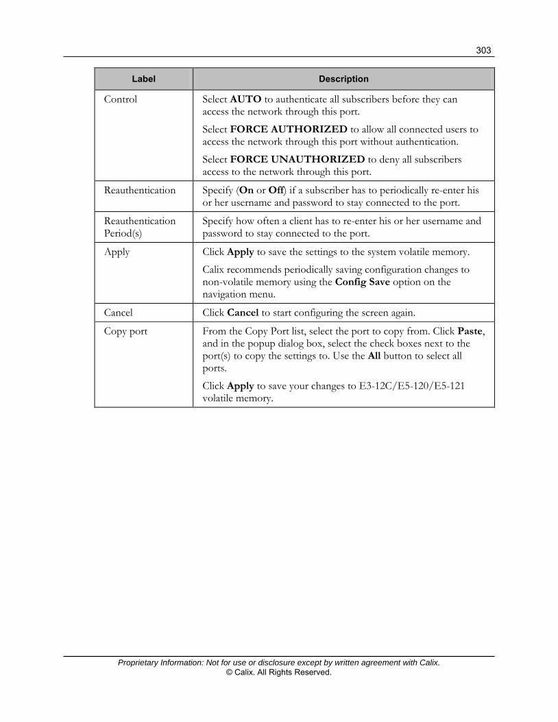
303
Proprietary Information: Not for use or disclosure except by written agreement with Calix. © Calix. All Rights Reserved.
Label Description
Control Select AUTO to authenticate all subscribers before they can access the network through this port.
Select FORCE AUTHORIZED to allow all connected users to access the network through this port without authentication.
Select FORCE UNAUTHORIZED to deny all subscribers access to the network through this port.
Reauthentication Specify (On or Off) if a subscriber has to periodically re-enter his or her username and password to stay connected to the port.
Reauthentication Period(s)
Specify how often a client has to re-enter his or her username and password to stay connected to the port.
Apply Click Apply to save the settings to the system volatile memory.
Calix recommends periodically saving configuration changes to non-volatile memory using the Config Save option on the navigation menu.
Cancel Click Cancel to start configuring the screen again.
Copy port From the Copy Port list, select the port to copy from. Click Paste, and in the popup dialog box, select the check boxes next to the port(s) to copy the settings to. Use the All button to select all ports.
Click Apply to save your changes to E3-12C/E5-120/E5-121 volatile memory.

304
Proprietary Information: Not for use or disclosure except by written agreement with Calix. © Calix. All Rights Reserved.
Port Security
Port security allows you to restrict the number of MAC addresses that can be learned on a port. The E3-12C/E5-120/E5-121 can learn up to 4,000 MAC addresses.
Port Security Screen
Use this screen to view and provision port security.
To open the Port Security screen
On the navigation menu, click Advanced Applications > Port Security.

305
Proprietary Information: Not for use or disclosure except by written agreement with Calix. © Calix. All Rights Reserved.
The following table describes the elements of the Port Security screen:
Label Description
Port This field displays a port number.
Enable Select the Enable check box to restrict the number of MAC addresses that can be learned on the port. Clear this check box to not limit the number of MAC addresses that can be learned on the port.
Limited Number of Learned MAC Address
Specify how many MAC addresses the E3-12C/E5-120/E5-121 can learn on this port. The range is 1 through 128.
Note: If you also use MAC filtering on a port, Calix recommends that you set this limit to be equal to or greater than the number of MAC filter entries you configure.
Apply Click Apply to save the settings to the system volatile memory.
Calix recommends periodically saving configuration changes to non-volatile memory using the Config Save option on the navigation menu.
Cancel Click Cancel to start configuring the screen again.
Copy Port
Paste
Do the following to copy settings from one port to another port or ports: Select the number of the port from which you want to copy
settings. Click Paste to open the port selection dialog box.
Select which ports to apply the settings. (Click All to select
every port or click None to clear all of the check boxes.) Click Apply to paste the settings.

306
Proprietary Information: Not for use or disclosure except by written agreement with Calix. © Calix. All Rights Reserved.
Access Control
Use the Access Control screen to configure SNMP and enable/disable remote service access.
For a list of supported MIBs, see the publication, OSS Integration for Calix E-Series Northbound Interfaces.
To open the Access Control screen
On the navigation menu, click Advanced Applications > Access Control.
Access Control Overview
A console port or Telnet session can coexist with one FTP session, a Web Configurator session, and/or limitless SNMP access control sessions.
Console Port Telnet FTP Web SNMP
Number of sessions allowed 1 5 1 No limit No limit
SNMP
Simple Network Management Protocol (SNMP) is a protocol used for exchanging management information between network devices. SNMP is a member of TCP/IP protocol suite. A manager station can manage and monitor the E3-12C/E5-120/E5-121 through the network via SNMP version one (SNMPv1) and/or SNMP version 2c.
The following graphic shows an SNMP management operation. SNMP is only available when TCP/IP is configured.
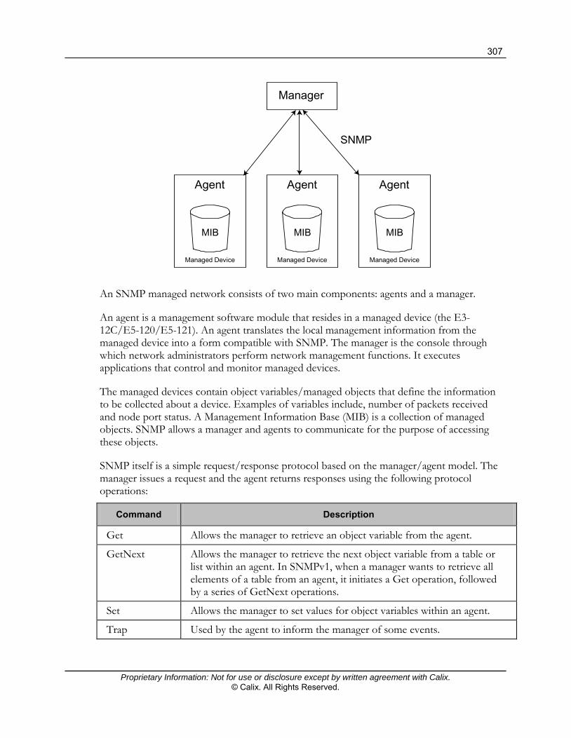
307
Proprietary Information: Not for use or disclosure except by written agreement with Calix. © Calix. All Rights Reserved.
Agent
Managed Device
MIB
Agent
Managed Device
MIB
Agent
Managed Device
MIB
Manager
SNMP
An SNMP managed network consists of two main components: agents and a manager.
An agent is a management software module that resides in a managed device (the E3-12C/E5-120/E5-121). An agent translates the local management information from the managed device into a form compatible with SNMP. The manager is the console through which network administrators perform network management functions. It executes applications that control and monitor managed devices.
The managed devices contain object variables/managed objects that define the information to be collected about a device. Examples of variables include, number of packets received and node port status. A Management Information Base (MIB) is a collection of managed objects. SNMP allows a manager and agents to communicate for the purpose of accessing these objects.
SNMP itself is a simple request/response protocol based on the manager/agent model. The manager issues a request and the agent returns responses using the following protocol operations:
Command Description
Get Allows the manager to retrieve an object variable from the agent.
GetNext Allows the manager to retrieve the next object variable from a table or list within an agent. In SNMPv1, when a manager wants to retrieve all elements of a table from an agent, it initiates a Get operation, followed by a series of GetNext operations.
Set Allows the manager to set values for object variables within an agent.
Trap Used by the agent to inform the manager of some events.

308
Proprietary Information: Not for use or disclosure except by written agreement with Calix. © Calix. All Rights Reserved.
SNMP Traps
The E3-12C/E5-120/E5-121 can send the following SNMP traps to an SNMP manager when an event occurs. XTUC refers to the downstream channel (for traffic going from the E3-12C/E5-120/E5-121 to the subscriber). XTUR refers to the upstream channel (for traffic coming from the subscriber to the E3-12C/E5-120/E5-121).
Trap Name The trap is sent when ...
coldStart The E3-12C/E5-120/E5-121 is turned on.
warmStart The E3-12C/E5-120/E5-121 restarts.
linkDown The Ethernet link is down. Enterprise specific (xdsl_xtuc_los) traps are sent when an xDSL link is down.
linkUp The Ethernet or xDSL link comes up.
reboot The system is going to reboot. The variable is the reason for the system reboot.
overheat The system is overheated. The variable is the current system temperature in Celsius.
overheatOver The system is no longer overheated. The variable is the current system temperature in Celsius.
fanRpmLow The RPM of the fan is too low. The variable is the current RPM of the fan.
fanRpmNormal The RPM of the fan is back within the normal range. The variable is the current RPM of the fan.
voltageOutOfRange The voltage of the system is out of the normal range. The variable is the current voltage of the system in volts.
voltageNormal The voltage of the system is back within the normal range. The variable is the current voltage of the system in volts.
extAlarmInputTrigger There is an external alarm input.
extAlarmInputRelease The external alarm input stops.
thermalSensorFailure The thermal sensor fails.
alarmRisingThreshold Remote Network Monitoring (RMON) values have exceeded the predefined thresholds. You can use an SNMP Management Information Base (MIB) to configure RMON thresholds. (RMON is a standard for displaying packet statistics. Refer to RFC2819 for more information.)
alarmFallingThreshold The RMON values have returned to normal.
sysAlarmSvrtyChange Alarm severity is changed.
sysMacAntiSpoofing The E3-12C/E5-120/E5-121 has detected the same MAC address on more than one subscriber port.
vdslPerfLofsThreshNotification A Loss Of Frame has occurred within 15 minutes for the XTUC has reached the threshold.
vdslPerfLossThreshNotification A Loss Of Signal has occurred within 15 minutes for the XTUC has reached the threshold.
vdslPerfLprsThreshNotification The number of times a Loss Of Power has occurred within 15 minutes for the XTUC has reached the threshold.
vdslPerfLolsThreshNotification The number of times a Loss Of Link has occurred within 15 minutes for the XTUC has reached the threshold.
vdslPerfESsThreshNotification The number of error seconds within 15 minutes for the XTUC has reached the threshold.
vdslPerfSESsThreshNotification The number of severely errored seconds within 15 minutes for the XTUC has reached the threshold.

309
Proprietary Information: Not for use or disclosure except by written agreement with Calix. © Calix. All Rights Reserved.
Trap Name The trap is sent when ...
vdslPerfUASsThreshNotification The number of Unavailable seconds within 15 minutes for the XTUC has reached the threshold.
voipBatteryFail The E3-12C/E5-121 device has detected a battery fault.
voipBatteryClear The E3-12C/E5-121 device has detected a battery fault has cleared.
voipClockFail The E3-12C/E5-121 device has detected a clock fault.
voipClockClear The E3-12C/E5-121 device has detected a clock has fault cleared.
voipRingerFault The E3-12C/E5-121 device has detected a Ringer Fault.
voipRingerClear The E3-12C/E5-121 device has detected a Ringer Fault has cleared.
voipTempError Thermal overload has been detected on line (E3-12C/E5-121 only).
voipTempClear Thermal overload detected on line has cleared (E3-12C/E5-121 only).
voipDcPowerFail A DC fault has been detected on line (E3-12C/E5-121 only).
voipDcPowerClear A DC fault detected on line has cleared (E3-12C/E5-121 only).
voipAcPowerFail An AC fault has been detected on line (E3-12C/E5-121 only).
voipAcPowerClear An AC fault detected on line has cleared (E3-12C/E5-121 only).
xdslAtucLof A Loss Of Frame is detected on the XTUC.
xdslAturLof A Loss Of Frame is detected on the XTUR.
xdslXtucLos A Loss Of Signal is detected on the XTUC.
xdslAturLos A Loss Of Signal is detected on the XTUR.
xdslAturLpr This trap is sent when a Loss Of Power is detected on the XTUR.
xdslAtucLofClear The Loss Of Frame detected on the XTUC is over.
xdslAturLofClear The Loss Of Frame detected on the XTUR is over.
xdslAtucLosClear The Loss Of Signal detected on the XTUC is over.
xdslAturLosClear The Loss Of Signal detected on the XTUR is over.
xdslAturLprClear The Loss Of Power detected on the XTUR is over.

310
Proprietary Information: Not for use or disclosure except by written agreement with Calix. © Calix. All Rights Reserved.
SNMP Screen
Use this screen to configure SNMP access, community strings, SNMP traps, and a trusted host computer. SNMP community strings authenticate access and function as embedded passwords.
To open the SNMP screen
On the navigation menu, click Advanced Applications > Access Control > SNMP.
The following table describes the elements of the SNMP screen:
Element Description
Up Click Up to go back to the previous screen.
Get Community Enter the get community, which is the password for the incoming Get- and GetNext- requests from the management station.
Set Community Enter the set community, which is the password for incoming Set- requests from the management station.
Trap Community
Enter the trap community, which is the password sent with each trap to the SNMP manager.
Trap Destination 1 through 4
Enter the IP address of a station to send your SNMP traps to.
Port Enter the port number upon which the station listens for SNMP traps.

311
Proprietary Information: Not for use or disclosure except by written agreement with Calix. © Calix. All Rights Reserved.
Element Description
Trusted Host A “trusted host” is a computer that is allowed to use SNMP with the E3-12C/E5-120/E5-121.
A setting of 0.0.0.0 allows any computer to use SNMP to access the E3-12C/E5-120/E5-121.
Specify an IP address to allow only the computer with that IP address to use SNMP to access the E3-12C/E5-120/E5-121.
Apply Click Apply to save the settings to the system volatile memory.
Calix recommends periodically saving configuration changes to non-volatile memory using the Config Save option on the navigation menu.
Cancel Click Cancel to begin configuring this screen afresh.
Service Access Control Screen
Use this screen to activate the service type and configure the service port numbers.
To open the Service Access Control screen
On the navigation menu, click Advanced Applications > Access Control > Service Access Control.
The following table describes the elements of the Service Access Control screen:
Label Description
Up Click Up to go back to the previous screen.
Services Services you may use to access the E3-12C/E5-120/E5-121 are listed here.
Active Select the Active check boxes for the corresponding services that you want to allow access to the E3-12C/E5-120/E5-121.
Server For Telnet, FTP, or web services, you can change the default service port

312
Proprietary Information: Not for use or disclosure except by written agreement with Calix. © Calix. All Rights Reserved.
Label Description
Port by typing the new port number in the Server Port field. If you change the default port number then you will have to let people (who want to use the service) know the new port number for that service.
Apply Click Apply to save the settings to the system volatile memory.
Calix recommends periodically saving configuration changes to non-volatile memory using the Config Save option on the navigation menu.
Cancel Click Cancel to begin re-configuring this screen.
Remote Management Screen
Use this screen to configure the IP address ranges of trusted computers that manage the E3-12C/E5-120/E5-121.
To open the Remote Management screen
On the navigation menu, click Advanced Applications > Access Control > Secured Client.

313
Proprietary Information: Not for use or disclosure except by written agreement with Calix. © Calix. All Rights Reserved.
The following table describes the elements of the Remote Management screen:
Element Description
Up Click Up to go back to the previous screen.
Index The client set index number. A “client set” is a group of one or more “trusted computers” from which an administrator can use a service to manage the E3-12C/E5-120/E5-121.
Enable Select the Enable check box to activate this secured client set. Clear the check box if you want to temporarily disable the set without deleting it.
Start IP Address
End IP Address
Configure the IP address range of trusted computers from which you can manage the E3-12C/E5-120/E5-121.
The E3-12C/E5-120/E5-121 checks if the client IP address of a computer requesting a service or protocol matches the range set here. The E3-12C/E5-120/E5-121 immediately disconnects the session if it does not match.
Telnet/FTP/Web/ ICMP/SNMP
Select services that may be used for managing the E3-12C/E5-120/E5-121 from the specified trusted computers.
Apply Click Apply to save the settings to the system volatile memory.
Calix recommends periodically saving configuration changes to non-volatile memory using the Config Save option on the navigation menu.
Cancel Click Cancel to begin configuring this screen afresh.

314
Proprietary Information: Not for use or disclosure except by written agreement with Calix. © Calix. All Rights Reserved.

Proprietary Information: Not for use or disclosure except by written agreement with Calix. © Calix. All Rights Reserved.
Chapter 12
Troubleshooting and Maintenance
This section covers the following topics:
Working with alarms Alarm troubleshooting information Troubleshooting specific conditions Viewing and configuring system logs Monitoring performance data MAC table ARP table Maintenance features E3-12C/E5-120/E5-121 default settings
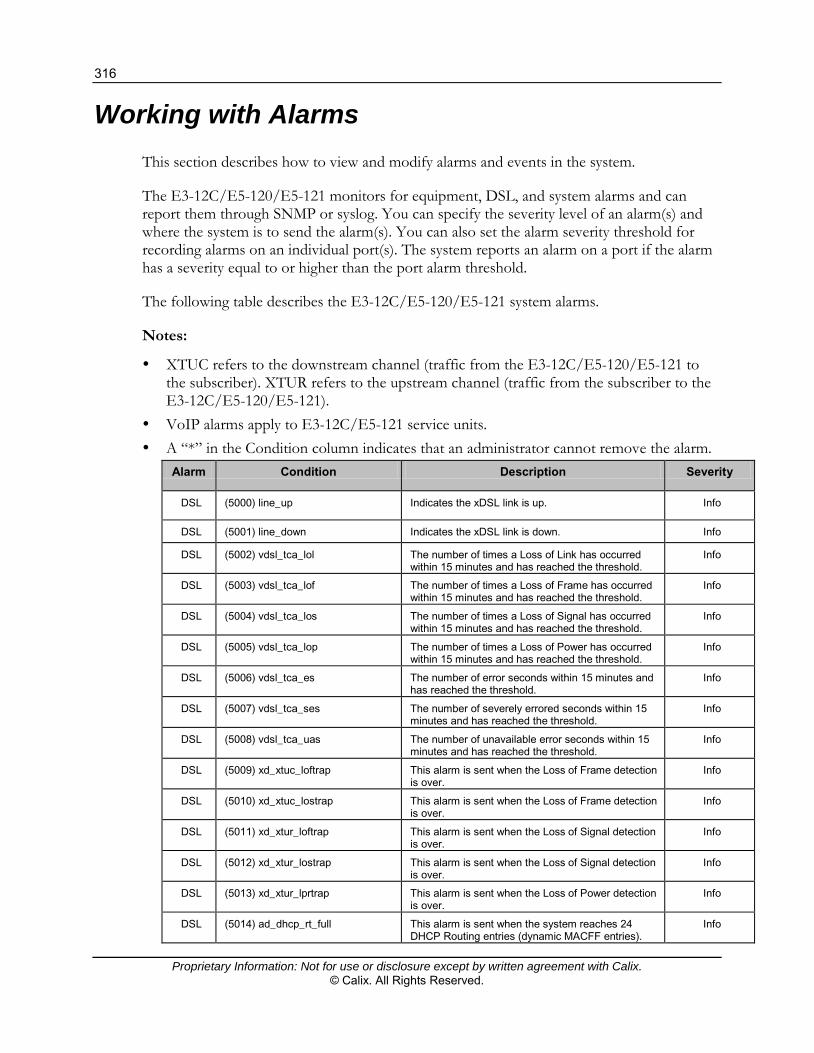
316
Proprietary Information: Not for use or disclosure except by written agreement with Calix. © Calix. All Rights Reserved.
Working with Alarms
This section describes how to view and modify alarms and events in the system.
The E3-12C/E5-120/E5-121 monitors for equipment, DSL, and system alarms and can report them through SNMP or syslog. You can specify the severity level of an alarm(s) and where the system is to send the alarm(s). You can also set the alarm severity threshold for recording alarms on an individual port(s). The system reports an alarm on a port if the alarm has a severity equal to or higher than the port alarm threshold.
The following table describes the E3-12C/E5-120/E5-121 system alarms.
Notes:
XTUC refers to the downstream channel (traffic from the E3-12C/E5-120/E5-121 to the subscriber). XTUR refers to the upstream channel (traffic from the subscriber to the E3-12C/E5-120/E5-121).
VoIP alarms apply to E3-12C/E5-121 service units. A “*” in the Condition column indicates that an administrator cannot remove the alarm.
Alarm Condition Description Severity
DSL (5000) line_up Indicates the xDSL link is up. Info
DSL (5001) line_down Indicates the xDSL link is down. Info
DSL (5002) vdsl_tca_lol The number of times a Loss of Link has occurred within 15 minutes and has reached the threshold.
Info
DSL (5003) vdsl_tca_lof The number of times a Loss of Frame has occurred within 15 minutes and has reached the threshold.
Info
DSL (5004) vdsl_tca_los The number of times a Loss of Signal has occurred within 15 minutes and has reached the threshold.
Info
DSL (5005) vdsl_tca_lop The number of times a Loss of Power has occurred within 15 minutes and has reached the threshold.
Info
DSL (5006) vdsl_tca_es The number of error seconds within 15 minutes and has reached the threshold.
Info
DSL (5007) vdsl_tca_ses The number of severely errored seconds within 15 minutes and has reached the threshold.
Info
DSL (5008) vdsl_tca_uas The number of unavailable error seconds within 15 minutes and has reached the threshold.
Info
DSL (5009) xd_xtuc_loftrap This alarm is sent when the Loss of Frame detection is over.
Info
DSL (5010) xd_xtuc_lostrap This alarm is sent when the Loss of Frame detection is over.
Info
DSL (5011) xd_xtur_loftrap This alarm is sent when the Loss of Signal detection is over.
Info
DSL (5012) xd_xtur_lostrap This alarm is sent when the Loss of Signal detection is over.
Info
DSL (5013) xd_xtur_lprtrap This alarm is sent when the Loss of Power detection is over.
Info
DSL (5014) ad_dhcp_rt_full This alarm is sent when the system reaches 24 DHCP Routing entries (dynamic MACFF entries).
Info

317
Proprietary Information: Not for use or disclosure except by written agreement with Calix. © Calix. All Rights Reserved.
Alarm Condition Description Severity
DSL (5015) ad_dhcp_dm_conflict This alarm is sent when the entered DHCP Gateway IP and the entered subscriber's IP are not in the same subnet.
Info
DSL (5016) ad_dhcp_entry_full This alarm is sent when a subscriber port reaches 32 DHCP entries.
Info
DSL (5017) ad_dhcp_ip_dup This alarm is sent when two DHCP entries have duplicate IP addresses but a different MAC address, VLAN, subscriber port, or subnet mask.
Info
DSL (5018) ad_dhcp_mac_dup This alarm is sent when two DHCP entries have duplicate MAC addresses but a different IP, subscriber port, or subnet mask.
Info
Eqpt (10000) vol_err* The input voltage (Vn) is lower than the low-threshold or higher than the high-threshold.
Critical
Eqpt (10001) temp_err* The temperature (Tn) is higher than the high-threshold or lower than the low-threshold.
Critical
Eqpt (10002) fan_err* The fan RPM ‘n’ is over the high-threshold or lower than the low-threshold.
See also fan_err (Fan error) (on page 327).
Critical
Eqpt (10003) hw_rtc_fail* The real-time chip diagnosis test failed. Critical
Eqpt (10004) hw_mon_fail* The hardware monitor diagnosis test failed. Critical
Eqpt (10005) cold_start* Indicates a system cold-start. Info
Eqpt (10006) warm_start* Indicates a system warm-start. Info
Eqpt (10007) alm_input* An alarm condition has been detected by an external alm_input.
Critical
Eqpt (10008) voip_battery_fail* There is a VoIP battery fault. Critical
Eqpt (10009) voip_clock_fail* There is a VoIP clock fault. Critical
Eqpt (10010) voip_ringer_fault * There is a VoIP ringer fault. Critical
Eqpt (10011) alm_input2* An alarm condition has been detected by an external alm_input2.
Critical
Eqpt (10012) alm_input3* An alarm condition has been detected by an external alm_input3.
Critical
Sys (15000) reboot* The system restarted. Info
Sys (15001) aco* An administrator cutoff (canceled) an alarm. Info
Sys (15002) alm_clear* An administrator cleared the alarm. Info
Sys (15003) login_fail A user typed an incorrect name or password when logging into Web Configurator and failed to log in. See also sysLogin_fail (on page 328)
Minor
Sys (15004) anti_spoofing See anti_spoofing (on page 326). Minor
Sys (15005) svrty_change There has been a change to the alarm severity. Info
ENET (20000) up* A Gigabit Ethernet interface is up. Info
ENET (20001) down A Gigabit Ethernet interface is down. Major
VoIP (25000) voip_temp_error* The temperature of the VoIP module has reached 165° C. The E5 releases this alarm when the temperature goes down to 150° C or below.
Critical
VoIP (25001) voip_dc_power_fail* A DC power fault. Critical
VoIP (25002) voip_ac_power_fail* An AC power fault. Critical
VoIP (25003) voip_ring_timer_fail* A firmware fault occurs when the E5 fails to start in SIP mode.
Info

318
Proprietary Information: Not for use or disclosure except by written agreement with Calix. © Calix. All Rights Reserved.
Alarm Condition Description Severity
VoIP (25004) voip_ring_rsrce_fail* The number of current incoming VoIP calls has exceeded the total ringer equivalency numbers (RENs) the E5 can support. Note: The E5 only supports one REN for each subscriber port at the time.
Info
VoIP (25006) voip_call_setup_failed A call attempt failed because it exceeded the maximum number of active calls.
Info
VoIP (25007) voip_call_threshold-violate The current active RTP session is over the alarm threshold setting for the number of active calls.
Minor
Intf (30000) cfm_error A Continuity Fault Management (CFM) error occurs after performing a loopback or linktrace test when one of the maintenance endpoints or intermediate points cannot be reached.
Info
Alarm Event Setup Screen
The Alarm Event Setup screen lists the alarms that the system can generate along with the severity levels of the alarms and where the system is to send them.
To open the Alarm Event Setup screen
On the navigation menu, click Alarms > Alarm Event Setup.
The following table describes the elements of the Alarm Event Setup screen:
Element Description
Index The index number of the alarm in the list.
To specify the severity level of an alarm(s) and where the system is to send the alarm(s), click the Index number (for details, see the procedure below).
Alarm The alarm category for the alarm. Eqpt represents equipment alarms. DSL represents Digital Subscriber Line (DSL) alarms. Enet represents Ethernet alarms. Sys represents system alarms. VoIP represents voice over IP alarms (E3-12C/E5-
121 only).
Condition Code The condition code number for the specific alarm message.
Condition A text description for the condition that applies the alarm.

319
Proprietary Information: Not for use or disclosure except by written agreement with Calix. © Calix. All Rights Reserved.
Element Description
Facility For alarms that are sent to a syslog server, the log facility (local1 to local7) on the syslog server where the system is to log the alarm.
SNMP Displays "V" if the system is to send this alarm to an SNMP server. A dash "-" displays if the system does not send this alarm to an SNMP server.
Syslog Displays "V" if the system is to send this alarm to a syslog server. A dash "-" displays if the system does not send this alarm to a syslog server.
Severity The alarm severity level (critical, major, minor, or info).
Clearable Displays "V" if the alarm clear command removes the alarm from the system. A dash "-" displays if the alarm clear command does not remove the alarm from the system.
To edit an alarm setup
1. On the navigation menu, click Alarms > Alarm Event Setup to open the Alarm Event Setup screen.
2. Click the alarm index number to open the edit screen.
The edit screen opens in a separate browser window.
3. Using the above table as a reference, edit the Facility, SNMP, Syslog, Severity, and
Clearable settings per site requirements.
4. Click Apply to save the new settings.
5. Click Close to return to the Alarm Event Setup screen.

320
Proprietary Information: Not for use or disclosure except by written agreement with Calix. © Calix. All Rights Reserved.
Viewing Alarms
This topic describes how to view alarms that are currently in the system.
To view the alarms currently in the system
1. On the navigation menu, click Alarms > Alarm Status.
2. Select which type of alarms to display by severity (Critical, Major, or Minor), or select All to view all the alarms.
3. Click Refresh to update this screen.
4. Click Clear to erase the clearable alarm entries.
The alarm table has the following columns and fields:
No displays the index number of the alarm entry in the system.
Alarm displays the alarm category to which the alarm belongs.
Condition displays a text description for the condition under which the alarm applies.
Severity displays the alarm severity level (critical, major, minor or info).
Timestamp displays the month, day, hour, minute and second that the system created the log.
Source displays where the alarm originated. This is either a DSL port number, one of the Ethernet ports (ENET1 or 2), or “eqpt” for the system itself.
Page x of x identifies which page of information is displayed and the total number of pages of information.
Previous Page and Next Page display the preceding and following page of entries.
To view the alarm events that the E3-12C/E5-120/E5-121 can generate
This screen lists the alarms that the system can generate along with the severity levels of the alarms and where the system is to send them.
On the navigation menu, click Alarms > Alarm Event Setup.

321
Proprietary Information: Not for use or disclosure except by written agreement with Calix. © Calix. All Rights Reserved.
The alarm event table has the following columns:
Index displays the index number of the alarm in the list. Click the Index number to specify the severity level of an alarm(s) and where the system is to send the alarm(s).
Alarm displays the alarm category for the alarm.
Eqpt represents equipment alarms.
DSL represents Digital Subscriber Line (DSL) alarms.
Enet represents Ethernet alarms.
Sys represents system alarms.
VoIP represents voice-over-IP alarms (E3-12C/E5-121 only). Condition Code displays the condition code number for the specific alarm message. Condition displays a text description for the condition that applies the alarm. Facility displays the log facility (local1 through local7) on the syslog server where the
system is to log this alarm. This is for alarms that send alarms to a syslog server. SNMP displays "V" if the system is to send this alarm to an SNMP server. It displays "-"
if the system does not send this alarm to an SNMP server. Syslog displays "V" if the system is to send this alarm to a syslog server. It displays "-" if
the system does not send this alarm to a syslog server. Severity displays the alarm severity level (critical, major, minor, or info). Clearable displays "V" if the alarm clear command removes the alarm from the system.
It displays "-" if the alarm clear command does not remove the alarm from the system.
Setting Up Alarms
This topic describes how to:
Set the alarm severity threshold for recording alarms on an individual port. The system reports an alarm on a port if the alarm has a severity equal to or higher than the port’s threshold.
Specify the severity level of an alarm and where the system is to send the alarm.

322
Proprietary Information: Not for use or disclosure except by written agreement with Calix. © Calix. All Rights Reserved.
To set the alarm severity threshold of a port
1. On the navigation menu, click Alarms > Alarm Port Setup.
2. In the Severity list box, select an alarm severity level (Critical, Major, Minor, or Info) as the threshold for recording alarms on the corresponding port. Critical alarms are the most severe, major alarms are the second most severe, minor alarms are the third most severe, and info alarms are the least severe.
3. Click Add or Apply to save your changes to the system volatile memory.
4. (Recommended) On the navigation menu, use the Config Save option to save changes to non-volatile memory.
To specify alarm events
1. On the navigation menu, click Alarms > Alarm Event Setup to open the Alarm Event Setup screen.
323
Proprietary Information: Not for use or disclosure except by written agreement with Calix. © Calix. All Rights Reserved.
2. Click the alarm index number to open the edit screen.
Note: The edit screen opens in a separate browser window.
The alarm event edit table has the following columns:
Alarm displays the alarm category.
Eqpt represents equipment alarms.
DSL represents Digital Subscriber Line (DSL) alarms.
Enet represents Ethernet alarms.
Sys represents system alarms.
VoIP represents voice-over-IP alarms (E3-12C/E5-121 only).
Condition Code displays the condition code number for the specific alarm message.
Condition displays a text description for the condition that applies to the alarm.
Facility displays the he log facility (local1 through local7) has the device log the syslog messages to a particular file in the syslog server. Select a log facility (local1 through local7) from the Facility list box if this entry is for sending alarms to a syslog server. See your syslog program’s documentation for details.
SNMP selection has the system send this alarm to an SNMP server.
Syslog selection has the system send this alarm to a syslog server.
Severity selects an alarm severity level (critical, major, minor, or info) for this alarm. Critical alarms are the most severe, major alarms are the second most severe, minor alarms are the third most severe, and info alarms are the least severe.
Clearable selection allows administrators to use the management interface to remove an alarm report generated by this alarm event entry. Select the Clearable check box to keep an alarm report generated by this alarm event in the system until the conditions that caused the alarm report are no longer present.
3. Click Add or Apply to save your changes to the system volatile memory.
4. (Recommended) On the navigation menu, use the Config Save option to save changes to non-volatile memory.

324
Proprietary Information: Not for use or disclosure except by written agreement with Calix. © Calix. All Rights Reserved.
Viewing the Alarm History
This screen displays the historical alarms stored in the system.
To open the Alarm History tab
1. On the navigation menu, click Alarms > Alarm Status.
2. Click the Alarm History tab.
The following table describes the elements of the Alarm History tab:
Element Description
Alarm Type Select which type of alarms to display by severity (Critical, Major, or Minor), or select All to view all the alarms.
Display Order Specify the order in which the history alarms will be displayed. By default, the alarms will be displayed in reverse order.
Refresh Click Refresh to update this screen.
Clear Click Clear to erase the clearable alarm entries.
No The index number of the historical alarm entry in the system.
Alarm The alarm category to which the alarm belongs.
Condition A text description for the condition under which the alarm applies.
Severity The alarm severity level (critical, major, minor or info).
Timestamp The month, day, hour, minute and second that the system created the log.

325
Proprietary Information: Not for use or disclosure except by written agreement with Calix. © Calix. All Rights Reserved.
Element Description
Source Where the alarm originated: A DSL port number One of the Ethernet ports (enet 1 or 2) “eqpt” for the system itself
Page x of x Which page of information is displayed and the total number of pages of information. Select the page number in the Page list to display alarm entries on that page.

326
Proprietary Information: Not for use or disclosure except by written agreement with Calix. © Calix. All Rights Reserved.
Alarm Troubleshooting Information
alm_input, alm_input2, and alm_input3 (External Alarm Input)
An alarm condition has been detected by the corresponding external alarm input.
Severity
Critical
anti_spoofing
The E3-12C/E5-120/E5-121 has detected the same MAC address on more than one port.
Note the following:
There are two digits in the alarm. The first digit indicates where the MAC address is learned first, and the second digit indicates the offender. For example, (25 6) indicates that the MAC address was first learned on port 25 and port 6 is the offender.
Ports 1 to 48 indicate subscriber ports.
Ports 49 and 50 indicate Ethernet ports ENET1 and ENET2, respectively.
Severity
Minor
down
A Gigabit Ethernet interface is down.
Severity
Major

327
Proprietary Information: Not for use or disclosure except by written agreement with Calix. © Calix. All Rights Reserved.
fan_err (Fan error)
The fan RPM ‘n’ is over the high-threshold or lower than the low-threshold.
A fan_err or fanRpmLow (Fan RPM Error) alarm indicates the speed of one or more fans is too slow or too fast.
Recommended action
Each fan has a sensor that can detect and report the fan’s Revolutions Per Minute (RPM). Using the E5 Web browser interface, check the System Info screen for the current fan speed (RPM).
Remove, inspect, and reinsert the fan tray. Verify the fan module is operating properly. Make sure you can feel and hear the fans
working – working fans emit a low buzz and blow air. If necessary, replace the fan module.
Severity
Critical
hw_mon_fail (Hardware monitor diagnosis fails)
The hardware monitor diagnosis test failed.
Severity
Critical
hw_rtc_fail (RTC diagnosis test fails)
The real-time chip diagnosis test failed.
Severity
Critical

328
Proprietary Information: Not for use or disclosure except by written agreement with Calix. © Calix. All Rights Reserved.
sysLogin_fail (Login fail)
A user typed an incorrect name or password when logging into Web Configurator and failed to log in.
Recommended action
To clear the alarm, do one of the following:
In Calix Management System (CMS):
On the navigation tree select the alarmed node.
In the work area, click the Alarms tab.
In the Alarm Status tab, click Clear.
To refresh the CMS Alarm Table, below the Alarm Table, click Refresh. In Web Configurator or CMS Configurator cut-through:
On the navigation menu, click Alarms > Alarm Status.
In the Alarm Status tab, click Clear.
Severity
Minor
temp_err (Temperature error)
The temperature (Tn) is higher than the high-threshold or lower than the low-threshold.
Severity
Critical
voip_ac_power_fail (AC power fails)
An AC power fault.
Severity
Critical

329
Proprietary Information: Not for use or disclosure except by written agreement with Calix. © Calix. All Rights Reserved.
voip_battery_fail (Chip battery fail indication)
There is a VoIP battery fault.
Severity
Critical
voip_call_threshold_violate (Call threshold violation)
The current active RTP session is over the alarm threshold setting for the number of active calls.
Severity
Minor
voip_clock_fail (Chip clock fail indication)
There is a VoIP clock fault.
Severity
Critical
voip_dc_power_fail (DC power fails)
A DC power fault.
Severity
Critical
voip_ringer_fault (Ringer fault indication)
There is a VoIP ringer fault.
Severity
Critical

330
Proprietary Information: Not for use or disclosure except by written agreement with Calix. © Calix. All Rights Reserved.
voip_temp_error (Temperature error)
The temperature of the VoIP module has reached 165° C. The E5 releases this alarm when the temperature goes down to 150° C or below.
Severity
Critical
vol_err (Voltage error)
The input voltage (Vn) is lower than the low-threshold or higher than the high-threshold.
Severity
Critical

331
Proprietary Information: Not for use or disclosure except by written agreement with Calix. © Calix. All Rights Reserved.
Troubleshooting Specific Conditions
This section covers potential problems and possible corrective actions. After each problem description, appropriate steps are provided to help you to diagnose and solve the problem. For more information, contact the Calix Technical Assistance Center (TAC).
SYS or PWR LED Does Not Turn On
Issue
The SYS/PWR LED does not turn on.
Recommended action
To troubleshoot the SYS LED
1. Verify that the power cable is properly connected to the power supply and the power supply is operating normally.
2. Verify that you are using the correct power source.
Note: If applicable, make sure a fuse is not burned out. If burned out, replace the fuse.
The LED itself or the unit may be faulty. Contact the Calix Technical Assistance Center (TAC) for support.
ALM LED Is On
Issue
The ALM (alarm) LED lights when the E3-12C/E5-120/E5-121 is overheated, the fans are not working properly, the voltage readings are outside the tolerance levels, or an alarm has been detected on the ALARM input pins.
Recommended action
To troubleshoot the ALM LED
1. Use the statistics monitor command to verify the cause of the alarm.
See Step 2 if the unit is overheated; see Step 3 if the problem is with the fans; and see Step 4 if the voltages are out of the allowed ranges.
2. Ensure that the E3-12C/E5-120/E5-121 is installed in a well-ventilated area and that normal operation of the fans is not inhibited. Keep the bottom, top, and all sides clear of obstructions and away from the exhaust of other equipment.

332
Proprietary Information: Not for use or disclosure except by written agreement with Calix. © Calix. All Rights Reserved.
3. Make sure you can feel or hear the fans working – working fans emit a low buzz and blow air.
4. If the voltage levels are outside the allowed range, take a screen shot of the statistics monitor command display and contact the Calix Technical Assistance Center (TAC) for support.
SFP LNK LEDs Do Not Turn On
Note on optical power measurement: For E3-12C/E5-120/E5-121 service units, the SFP registers record optical power in milliwatts (mW) instead of dBm. To calculate dBm, use the formula: dBm = log10 (mW)*10.
Issue
The LEDs for one of the Small Form-factor Pluggable (SFP) slots do not turn on.
Recommended action
To troubleshoot the SFP LNK LED
1. Verify that the Ethernet port’s mode is set to match that of the peer Ethernet device.
2. Check the cable and connections between the SFP slot and the peer Ethernet device.
3. Check the mini GBIC transceiver.
4. Verify that the peer Ethernet device is functioning properly.
If the cable, transceiver, and peer Ethernet device are all OK and the LEDs stay off, there may be a problem with the SFP slot. Contact the Calix Technical Assistance Center (TAC) for support.

333
Proprietary Information: Not for use or disclosure except by written agreement with Calix. © Calix. All Rights Reserved.
100/1000 LEDs Do Not Turn On
Issue
A 100/1000 Ethernet port LED does not turn on.
Recommended action
To troubleshoot the 100/1000 LED
Note: Each 100/1000M RJ-45 Ethernet port is paired with a mini GBIC slot. The E3-12C/E5-120/E5-121 uses one connection per pair.
1. Check the Speed Mode settings in the ENET Port Setup screen. Make sure that the 100/1000 Ethernet port connection speed is set to match that of the port on the peer Ethernet device. When an Ethernet port is set to Auto, the E3-12C/E5-120/E5-121 tries to make a fiber connection first and does not attempt to use the RJ-45 port if the fiber connection is successful.
2. Check the Ethernet cable and connections between the 100/1000 Ethernet port and the peer Ethernet device.
Use 1000-BaseT 4-pair (8 wire) UTP CAT5 Ethernet cables with the RJ-45 interface.
3. Verify that the peer Ethernet device is functioning properly.
If the Ethernet cable and peer Ethernet device are both OK and the LEDs still stay off, there may be a problem with the port. Contact the Calix Technical Assistance Center (TAC) for support.
100/1000 Ethernet Port Data Transmission
Issue
The Ethernet port's LED is on, but data cannot be transmitted.
Recommended action
To troubleshoot the 100/1000 Ethernet port data transmission
1. Verify that the Ethernet port has the appropriate mode setting.
2. Verify that the E3-12C/E5-120/E5-121’s IP settings are properly configured.
3. Check the VLAN configuration.
4. Ping the E3-12C/E5-120/E5-121 from a computer behind the peer Ethernet device.

334
Proprietary Information: Not for use or disclosure except by written agreement with Calix. © Calix. All Rights Reserved.
5. If you cannot ping, check the Ethernet cable and connections between the Ethernet port and the Ethernet switch or router.
6. In daisy-chain configuration, if you enable RSTP, it is possible for RSTP to disable Ethernet port 1 (the uplink port).
DSL Data Transmission
Issue
The xDSL link is up, but data cannot be transmitted.
Recommended action
To troubleshoot xDSL data transmission
1. Check the port isolation setting.
Check to see that the VPI/VCI and multiplexing mode (LLC/VC) settings in the subscriber’s xDSL modem or router match those of the xDSL port.
If the subscriber is having problems with a video or other high-bandwidth services, make sure the E3-12C/E5-120/E5-121 xDSL port data rates are set high enough.
2. Check the VLAN configuration.
3. Ping the E3-12C/E5-120/E5-121 from the computer behind the xDSL modem or router.
4. If you cannot ping, connect a DSL modem to an xDSL port (that is known to work).
If the xDSL modem or router works with a different xDSL port, there may be a problem with the original port. Contact the Calix Technical Assistance Center (TAC) for support.
5. If using a different port does not work, try a different xDSL modem or router with the original port.
No Voice Service on a VDSL Connection
The E3-12C/E5-120/E5-121 has internal POTS (Plain Old Telephone Service) splitters that allow the telephone wiring used for VDSL connections to simultaneously carry normal voice conversations.
Issue
There is no voice service.

335
Proprietary Information: Not for use or disclosure except by written agreement with Calix. © Calix. All Rights Reserved.
Recommended action
To troubleshoot voice service
1. Verify that the subscriber's VDSL is working normally.
2. Verify that the subscriber has a POTS splitter properly installed.
3. Check the VDSL line pin assignments.
4. Check the telephone wire connections between the subscriber and the MDF(s).
5. Check the telephone wire and connections between the MDF(s) and VDSL port(s).
6. Check the telephone wire mapping on the MDF(s).
7. Verify that the in-house wiring works and is connected properly.
8. Repeat the steps above using a different VDSL port.
Video Tiling or Dropped Video Streams
Video tiling or dropped streams can occur after performing one of these setup activities:
Setting the IGMP mode to IGMP Proxy Configuring Residential Gateway services
Recommend actions
Review the recommended IGMP proxy configuration settings and troubleshooting tips as described in these topics:
IGMP Proxy Setup Considerations for Non-Residential Gateway Customers (on page 177) IGMP Proxy Settings for Residential Gateway Services (on page 175)
Local Server
Issue
The computer behind a DSL modem or router cannot access a local server connected to the E3-12C/E5-120/E5-121.

336
Proprietary Information: Not for use or disclosure except by written agreement with Calix. © Calix. All Rights Reserved.
Recommended action
To troubleshoot a local server
1. See No Voice on an VDSL Connection (on page 334) to make sure that the subscriber is able to transmit to the E3-12C/E5-120/E5-121.
2. Verify that the computer behind the DSL device has the correct gateway IP address configured.
3. Check the VLAN configuration (see VLAN (on page 284)).
4. Check the cable and connections between the E3-12C/E5-120/E5-121 and the local server.
5. Try to access another local server.
Note: If data can be transmitted to a different local server, the local server that could not be accessed may have a problem.
Data Rate
Issue
The SYNC-rate is not the same as the configured rate.
Recommended action
To troubleshoot the SYNC rate
1. Connect the xDSL modem or router directly to the xDSL port using a different telephone wire.
2. If the rates match, the quality of the telephone wiring that connects the subscriber to the xDSL port may be limiting the speed to a certain rate.

337
Proprietary Information: Not for use or disclosure except by written agreement with Calix. © Calix. All Rights Reserved.
Configured Settings
Issue
The configured settings do not take effect.
Recommended action
To troubleshoot the configured settings
1. Finish the configuration process.
2. Use the config save command to save the E3-12C/E5-120/E5-121 settings.
Password
If you forget your password, use the console port to reload the factory-default configuration file.
Related topic
Resetting the Defaults (on page 391)
SNMP
Issue
The SNMP manager server cannot get information from the E3-12C/E5-121.
Recommended action
To troubleshoot the SNMP server
1. Ping the E3-12C/E5-120/E5-121 from the SNMP server. If you cannot, check the cable, connections and IP configuration.
2. Check to see that the community (or trusted host) in the E3-12C/E5-121 matches the SNMP server’s community.
3. Verify that your computer's IP address matches a configured trusted host IP address (if configured).

338
Proprietary Information: Not for use or disclosure except by written agreement with Calix. © Calix. All Rights Reserved.
System Lockout
Any of the following could also lock you and others out from using in-band management (managing through the data ports).
Deleting the management VLAN (default is VLAN 1). Incorrectly configuring the CPU VLAN. Incorrectly configuring the access control settings. Disabling all ports.
Note: If you lock yourself (and others) out of the system, you can use the console port to reconfigure the system. For more information, see Resetting the Defaults (on page 391).
Telnet
Issue
No telnet access into the E3-12C/E5-120/E5-121.
Recommended action
To troubleshoot telnet access
1. Verify that the number of current telnet sessions does not exceed the maximum allowed number. You cannot have more than five combined telnet and SSH sessions at one time.
2. Verify that your computer IP address matches a configured secured client IP address (if configured). The E3-12C/E5-120/E5-121 immediately disconnects the telnet session if secured host IP addresses are configured and your computer IP address does not match one of them.
3. Verify that you have not disabled the telnet service or changed the server port number that the E3-12C/E5-120/E5-121 uses for telnet.
4. Ping the E3-12C/E5-120/E5-121 from your computer.
If you are able to ping the E3-12C/E5-120/E5-121 but are still unable to telnet, contact the distributor.
If you cannot ping the E3-12C/E5-120/E5-121, check the cable, connections and IP configuration.
Note: Incorrectly configuring the access control settings may lock you out from using in-band management. Try using the console port to reconfigure the system.

339
Proprietary Information: Not for use or disclosure except by written agreement with Calix. © Calix. All Rights Reserved.
Recovering the Firmware
Typically you use FTP or the Web Configurator to upload the E3-12C/E5-120/E5-121 firmware. If the E3-12C/E5-120/E5-121 will not start up, the firmware may be lost or corrupted. Use the following procedure to upload firmware to the E3-12C/E5-120/E5-121 only when you are unable to upload firmware through FTP.
Note: This procedure is for emergency situations only.
To upload the E3-12C/E5-120/E5-121 firmware
1. Obtain the firmware file, unzip it and save it in a folder on your computer.
2. Connect your computer to the console port and use terminal emulation software configured to the following parameters:
VT100 terminal emulation
9600 bps
No parity, 8 data bits, 1 stop bit
No flow control
3. Turn off the E3-12C/E5-120/E5-121 and turn it back on to restart it and begin a session.
4. When you see the message Press any key to enter Debug Mode within 3 seconds, press a key to enter debug mode.
5. Type atba5 after the Enter Debug Mode message (this changes the console port speed to 115200 bps).
6. Change the configuration of your terminal emulation software to use 115200 bps and reconnect to the E3-12C/E5-120/E5-121.
7. Type atur after the Enter Debug Mode message.
8. Wait for the Starting XMODEM upload message before activating XMODEM upload on your terminal.

340
Proprietary Information: Not for use or disclosure except by written agreement with Calix. © Calix. All Rights Reserved.
9. Click Transfer, then Send File to display the following screen. This is an example Xmodem configuration upload using HyperTerminal.
10. Type the firmware file's location, or click Browse to search for it. Select the 1K Xmodem protocol. Click Send.
11. After a successful firmware upload, type atgo to restart the E3-12C/E5-120/E5-121.
The console port speed automatically changes back to 9600 bps when the E3-12C/E5-120/E5-121 restarts.

341
Proprietary Information: Not for use or disclosure except by written agreement with Calix. © Calix. All Rights Reserved.
Rebooting an E3-12C/E5-120/E5-121
Use this function to restart the device without physically turning the power off. Rebooting does not affect the system configurations.
To reboot the system
1. On the navigation menu, click Management > Maintenance > Reboot System.
2. In the Set Reboot Timer box, type the number of seconds (5 to 1800) for the reboot timer (use 0 to reboot immediately).
3. Click Reboot.
4. Click OK to reboot the system.
5. Click OK.
It takes up to two minutes for the device to restart (does not affect the device's configuration).
If you set the reboot timer, you can cancel the reboot at any time before the timer runs out by clicking Cancel Reboot Timer.

342
Proprietary Information: Not for use or disclosure except by written agreement with Calix. © Calix. All Rights Reserved.
Viewing and Configuring System Logs
This topic describes how to view system logs.
The common format of the system logs is: <item no> <time> <process> <type> <log message>.
Element Description
<item no> The index number of the log entry.
<time> The time and date when the log was created.
<process> The process that created the log.
<type> Identifies the type of log:
"INFO" identifies an information log "WARN" identifies a warning log
<log message> The log’s detailed information.
To view and configure system logs
1. On the navigation menu, click Management > Diagnostics to open the Diagnostics screen.
2. To view the log of events in the multi-line text box, click Display.
3. To empty the text box and reset the log, click Clear.
The following table lists and describes the system log messages:
Log Message Type Description
xDSL <port> Link Up(SN=<seq no>): <ds rate>/<us rate>!
or
xDSL Link Info: NM:<ds NM>/<us NM>!
INFO An xDSL port established a connection.
<port> - port number
<seq no> - sequence number of the connection
<ds rate> - downstream rate
<us rate> - upstream rate
<us NM> - upstream noise margin
<ds NM> - downstream noise margin
xDSL <port> Link Down(SN=<seq no>)! WARN An xDSL port lost its connection.
<port> - port number
<seq no> - sequence number of the connection
Session Begin! INFO A console, telnet or FTP session has begun (see the <process> field for the type of session).
Session End! INFO A console telnet or FTP session has terminated (see the <process> field for the type of session).

343
Proprietary Information: Not for use or disclosure except by written agreement with Calix. © Calix. All Rights Reserved.
Log Message Type Description
Incorrect Password! WARN Someone attempted to use the wrong password to start a console, telnet or FTP session (see the <process> field for the type of session).
Received Firmware Checksum Error! WARN A checksum error was detected during an attempted FTP firmware upload.
Received Firmware Size too large! WARN The file size was too large with an attempted FTP firmware upload.
Received Firmware Invalid! WARN Someone attempted to upload a firmware file with a wrong identity via FTP.
Received File <file>! INFO A file was uploaded to the E3-12C/E5-120/E5-121 by FTP.
<file> - received file’s name
THERMO OVER TEMPERATURE: dev:<id> threshold:<threshold>(degree C) value:<temp>(degree C)!
WARN The temperature was too high at one of the temperature sensors.
<id> -
0: sensor near the xDSL chipset
1: sensor near the CPU
2: thermal sensor chip itself
<threshold> - threshold temperature
<temp> - temperature when the entry was logged
THERMO OVER TEMPERATURE released: dev:<id> threshold:<threshold>(degree C) value:<temp>(degree C)!
INFO The temperature at one of the temperature sensors has come back to normal.
<id>
0: sensor near the xDSL chipset
1: sensor near the CPU
2: thermal sensor chip itself
<threshold> - threshold temperature
<temp> - temperature when the entry was logged
THERMO OVER VOLTAGE: nominal:<nominal>(mV) value:<voltage> mV)!
WARN The voltage went outside of the accepted operating range.
<nominal> - nominal voltage of the DC power
<voltage> - voltage of the DC power when logged
THERMO OVER VOLTAGE released: nominal:<nominal>(mV) value:<voltage> (mV)!
INFO The voltage is back inside the accepted operating range.
<nominal> - nominal voltage of the DC power
<voltage> - voltage of the DC power when logged

344
Proprietary Information: Not for use or disclosure except by written agreement with Calix. © Calix. All Rights Reserved.
SysLog Screen
Use the SysLog screen to activate system logging and configure the IP address of the syslog server.
To open the Syslog screen
On the navigation menu, click Advanced Applications > SysLog.
The following table describes the elements of the SysLog screen:
Element Description
Enable Select the Enable check box to activate syslog (system logging) and then configure the syslog server IP address.
Syslog Server IP Enter the IP address of the syslog server.
Apply Click Apply to save the settings to the system volatile memory.
Calix recommends periodically saving configuration changes to non-volatile memory using the Config Save option on the navigation menu.
Cancel Click Cancel to start configuring the screen again.

345
Proprietary Information: Not for use or disclosure except by written agreement with Calix. © Calix. All Rights Reserved.
Monitoring Performance Data
This section shows you how to access the Home screen that has a port statistical summary with links to each port to view statistical details. The following sets of statistics are described:
Viewing Ethernet port statistics Viewing xDSL port statistics
Viewing Ethernet Port Statistics
This topic describes how to view the Ethernet Port Statistics.
To view the Ethernet port statistics
1. In the banner at the top of the screen, click Home (to the left of Logout).
2. In the Ethernet port list, under the ENET column, click a port number link (1 for ENET 1; 2 for ENET 2) to view the corresponding statistics:
Rx bytes: The number of octets of Ethernet frames received that are from 0 to 1518 octets in size, counting the ones in bad packets, not counting framing bits but counting Frame Check Sequence (FCS) octets. An octet is an 8-bit binary digit (byte).
Rx packets: The number of packets received on this port (including multicast, unicast, broadcast and bad packets).
Rx error fcs: The number of frames received with an integral length of 64 to 1518 octets and containing a Frame Check Sequence error.
Rx multicast: The number of good multicast frames received of 64 to 1518 octets in length (for non VLAN) or 1522 octets (for VLAN), not including Broadcast frames. Frames with range or length errors are also not taken into account.
Rx broadcast: The number of good broadcast frames received of 64 to 1518 octets in length (for non VLAN) or 1522 octets (for VLAN), not including multicast frames. Frames with range or length errors are also not taken into account.
Rx mac pause: The number of valid IEEE 802.3x Pause frames received on this port.
Rx fragments: The number of frames received that were less than 64 octets long, and contained an invalid FCS, including non-integral and integral lengths.
Rx error overrun: shows how many times an Ethernet transmitter overrun occurred.
Rx error mru: The number of received frames that were dropped due to exceeding the Maximum Receive Unit frame size.
Rx dropped: The number of received frames that were received into the E3-12C/E5-120/E5-121, but later dropped because of a lack of system resources.

346
Proprietary Information: Not for use or disclosure except by written agreement with Calix. © Calix. All Rights Reserved.
Rx jabber: The number of frames received that were longer than 1518 octets (non VLAN) or 1522 octets (VLAN) and contained an invalid FCS, including alignment errors.
Rx error alignment: The number of frames received that were 64 to 1518 (non VLAN) or 1522 (VLAN) octets long but contained an invalid FCS and a non-integral number of octets.
Rx oversize: The number of frames received that were bigger than 1518 (non VLAN) or 1522 (VLAN) octets and contained a valid FCS.
Rx undersize: The number of frames received that were less than 64 octets long and contained a valid FCS.
Tx bytes: The number of bytes that have been transmitted on this port. This includes collisions but not jam signal or preamble/Start of Frame Delimiter (SFD) bytes.
Tx packets: The number of packets transmitted on this port.
Tx multicast: The number of good multicast frames transmitted on this port (not including broadcast frames).
Tx broadcast: The number of broadcast frames transmitted on this port (not including multicast frames).
Tx mac_pause: The number of valid IEEE 802.3x Pause frames transmitted on this port.
Tx fragments: The number of transmitted frames that were less than 64 octets long, and with an incorrect FCS value.
Tx frames: The number of complete good frames transmitted on this port.
Tx error underrun: The number of outgoing frames that were less than 64 octets long.
Tx undersize: The number of frames transmitted that were less than 64 octets long and contained a valid FCS.
Tx jabber: The number of frames transmitted that were longer than 1518 octets (non VLAN) or 1522 octets (VLAN) and contained an incorrect FCS value.
Tx oversize: The number of frames transmitted that were bigger than 1518 octets (non VLAN) or 1522 (VLAN) and contained a valid FCS.
packet( ): The number of frames received and transmitted (including bad frames) that were in the octets in length range specified within parentheses (includes FCS octets, but excludes framing bits).
packet(total): The total number of received and transmitted packets.
broadcast(total): The total number of received and transmitted broadcast frames.

347
Proprietary Information: Not for use or disclosure except by written agreement with Calix. © Calix. All Rights Reserved.
multicast(total): The total number of received and transmitted multicast frames.
octet(total): The total number of received and transmitted octets (unicast, multicast and broadcast).
3. At the bottom portion of the screen, do the following:
a. In the Poll Interval(s) box, type a value (in seconds) that controls how often the screen refreshes, and then click Set Interval.
b. Click Stop to halt the system statistic polling.
c. In the Port box, select a port that you want to erase the recorded statistical information for that port, and then click Clear Counter.
d. Click Reset to set the Poll Interval(s) and Port fields to their default values and to refresh the screen.
4. To view statistics for another port, in the Port list, select the port.
5. To return to the Home screen, at the top right of the screen, click Up.
Viewing xDSL Port Statistics
This topic describes how to view the xDSL Port Statistics.
To view the xDSL port statistics
1. In the banner at the top of the screen, click Home (to the left of Logout).
2. In the xDSL port list, under the xDSL column, click a port number link to view the corresponding statistics:
Port Name: user-configurable name for the port. If no name has been configured, the field is blank.
Tx packets: The number of packets transmitted on this port.
Rx packets: The number of packets received on this port.
Tx broadcast packets: The number of broadcast packets transmitted on this port.
Rx broadcast packets: The number of broadcast packets received on this port.
Tx discard packets: The number of outgoing packets that were dropped on this port. Note: This counter is always “0”; the E3-12C/E5-120/E5-121 does not discard packets that it sends.

348
Proprietary Information: Not for use or disclosure except by written agreement with Calix. © Calix. All Rights Reserved.
Rx discard packets: The number of received packets that were dropped on this port. Possible reasons for the discarding of received (rx) packets are: The packet filter is enabled and the packets matched a packet filter. The MAC filter is enabled and the E3-12C/E5-120/E5-121 dropped the packets
according to the MAC filter’s configuration. The packets contained frames with an invalid VLAN ID.
Errors: The number of AAL5 frames received with CRC errors. Tx rate: The number of bytes per second transmitted on this port. Rx rate: The data rate received on this port (in Kbps). Tx utilization: The percent of utilization for traffic transmitted on the subscriber
port. Rx utilization: The percent of utilization for traffic received on the subscriber port. Tx bytes: The number of bytes that have been transmitted on this port. Rx bytes: The number of bytes that have been received on this port. VPI/VCI: The Virtual Path Identifier (VPI) and Virtual Circuit Identifier (VCI) of
any configured channels on this port. Note: For VDSL ports on E3-12C, E5-120, and E5-121 service units, vdsl displays.
Tx Packets: The number of packets transmitted on each channel. Rx Packets: The number of packets received on each channel. Tx rate: The number of bytes per second transmitted on each channel. Rx rate: The number of bytes per second received on each channel. Tx cells: (E5-110 and E5-111 service units only) The number of ATM cells
transmitted on each channel. Rx cells: (E5-110 and E5-111 service units only) The number of ATM cells received
on each channel. Errors: The number of error packets on each channel.
3. At the bottom portion of the screen, do the following:
a. In the Poll Interval(s) box, type a value (in seconds) that controls how often the screen refreshes, and then click Set Interval.
b. Click Stop to halt the system statistic polling.
c. In the Port box, select a port that you want to erase the recorded statistical information for that port, and then click Clear Counter.
d. Click Reset to set the Poll Interval(s) and Port fields to their default values and to refresh the screen.
4. To view the statistics for another port, in the Port list, select the port.
5. To return to the Home screen, at the top right of the screen, click Up.

349
Proprietary Information: Not for use or disclosure except by written agreement with Calix. © Calix. All Rights Reserved.
RMON Statistics
The RMON Statistics screen displays Remote Network Monitoring (RMON) statistics for a port.
To open the RMON tab
1. In the banner at the top of the screen, to the left of Logout, click Home.
2. In the port lists, under the ENET or xDSL column, click a port number link.
3. Click the RMON tab.
4. At the bottom portion of the screen, you can do one or more of the following:
a. To control how often the screen refreshes, in the Poll Interval(s) box type a value (in seconds) and then click Set Interval.
b. To stop the system statistical polling, click Stop.
c. To erase the recorded statistical information for a port, in the Port list, select the port and then click Clear Counter.
d. To set the Poll Interval(s) and Port fields back to the default values (40 and 1, respectively) and refresh the screen, click Reset Port.

350
Proprietary Information: Not for use or disclosure except by written agreement with Calix. © Calix. All Rights Reserved.
5. To view the RMON history for the port, click Enet1 or Enet2.
The RMON history opens in a browser window.
6. To return to the previous screen, click the Port Statistics tab.
The following table describes the elements of the RMON statistics tab:
Label Description
EtherStatsDropEvents The total number of packets that were dropped on this port.
EtherStatsOctets The total number of octets received/transmitted on this port.
EtherStatsPkts The total number of good packets received/transmitted on this port.
EtherStatsBroadcastPkts The total number of broadcast packets received/transmitted on this port.
EtherStatsMulticastPkts The total number of multicast packets received/transmitted on this port.
EtherStatsCRCAlignErrors The total number of CRC (Cyclical Redundancy Check) alignment errors on this port.
EtherStatsUndersizePkts The total number of packets that were too small received/transmitted on this port.
EtherStatsOversizePkts The total number of packets that were too big received/transmitted on this port.
EtherStatsFragments The number of frames received/transmitted that were less than 64 octets long, and contained an invalid FCS, including non-integral and integral lengths.
EtherStatsJabbers The number of frames received/transmitted that were longer than 1518 octets (non VLAN) or 1522 octets (VLAN) and contained an invalid FCS, including alignment errors.
EtherStatsCollisions The number of frames for which transmission failed due to excessive collisions. Excessive collision is defined as the number of maximum collisions before the re-transmission count is reset.
EtherStats64Octets (†) The number of frames received/transmitted (including bad frames) that were 64 octets or less in length.
EtherStats65to127Octets (†) The number of frames received/transmitted (including bad frames) that were 65 to 127 octets in length.

351
Proprietary Information: Not for use or disclosure except by written agreement with Calix. © Calix. All Rights Reserved.
Label Description
EtherStats128to255Octets (†)
The number of frames received and transmitted (including bad frames) that were 128 to 255 octets in length.
EtherStats256to511Octets (†)
The number of frames received/transmitted (including bad frames) that were 256 to 511 octets in length.
EtherStats512to1023Octets (†)
The number of frames received/transmitted (including bad frames) that were 512 to 1023 octets in length.
EtherStats1024to1518Octets (†)
The number of frames received/transmitted (including bad frames) that were 1024 to 1518 octets in length.
† Includes FCS octets but excludes framing bits.
RMON History Screen
The RMON History screen show general information about history samples.
To open the RMON History screen
1. Click Home in any Web Configurator screen to open the Home screen.
2. Click an xDSL port number in the Home screen to open the (DSL) Port Statistics tab.
3. Click the RMON tab.
4. Click the port number on any RMON Statistics screen to open the RMON History screen.
Note: Clicking the port number opens the RMON History screen in a separate Web browser window.

352
Proprietary Information: Not for use or disclosure except by written agreement with Calix. © Calix. All Rights Reserved.
The following table describes the elements of the RMON History screen:
Label Description
Index:Interval Select the index of the sample interval and the desired data sampling time (in seconds).
Apply Click Apply to use the selected data sampling time.
Refresh Click Refresh to update this screen.
Sample Index The sample number.
Interval Start The data sampling time.
Pkts The number of packets received or transmitted since the last sample time.
BroadcastPkts The number of broadcast packets received or transmitted since the last sample time.
MulticastPkts The number of multicast packets received/transmitted since the last sample time.
Utilization The port utilization status.

353
Proprietary Information: Not for use or disclosure except by written agreement with Calix. © Calix. All Rights Reserved.
RMON History Detail Screen
The RMON History Detail screen show detailed RMON history information.
To open the RMON History Detail screen
1. Click Home in any Web Configurator screen to open the Home screen.
2. Click an xDSL port number link to open the (DSL) Port Statistics tab.
3. Click the RMON tab.
4. Click the port number on any RMON Statistics screen to open the RMON History screen.
Note: Clicking the port number opens the RMON History screen in a separate Web browser window.
5. Click an index number on the RMON History screen to open the RMON History Detail screen.
The following table describes the elements of the RMON History Detail screen:
Label Description
UP Click UP to return to the previous screen.
Refresh Click Refresh to update this screen.
Index The index of the sample interval.
Sample Index The sample number.
Interval Start The data sampling time.

354
Proprietary Information: Not for use or disclosure except by written agreement with Calix. © Calix. All Rights Reserved.
Label Description
Drop Events The total number of packets that were dropped in the sampling period.
Octets The total number of octets received/transmitted in the sampling period.
Pkts The total number of good packets received/transmitted in the sampling period.
BroadcastPkts The total number of broadcast packets received/transmitted in the sampling period.
MulticastPkts The total number of multicast packets received/transmitted in the sampling period.
CRCAlignErrors The total number of Cyclical Redundancy Check (CRC) alignment errors in the sampling period.
UndersizePkts The total number of packets that were too small received/transmitted in the sampling period.
OversizePkts The total number of packets that were too big received/transmitted in the sampling period.
Fragments The number of frames received/transmitted that were less than 64 octets long, and contained an invalid FCS, including non-integral and integral lengths.
Jabbers The number of frames received/transmitted that were longer than 1518 octets (non VLAN) or 1522 octets (VLAN) and contained an invalid FCS, including alignment errors.
Collisions The number of frames for which transmission failed due to excessive collisions. Excessive collision is defined as the number of maximum collisions before the retransmission count is reset.
Utilization The port utilization status in the sampling period.

355
Proprietary Information: Not for use or disclosure except by written agreement with Calix. © Calix. All Rights Reserved.
xDSL Line Data
This section describes the xDSL Line Rate Info, Line Data, and Line Performance screens.
xDSL Line Rate Info Tab
This screen displays xDSL port line operating values.
Note: Information obtained prior to training to a steady state transition is out-of-date and therefore invalid.
To open the Line Rate Info tab
1. On the navigation menu, click Basic Settings > xDSL Line Data.
2. Click the Line Rate Info tab.
The following table describes the elements of the xDSL Line Rate Info tab:
Element Description
Port Use the Port list box to select a port to view information.
Refresh Click Refresh to display updated information.
Port Name Displays the name of the port.
Rate Display the transmission rates. "Link Down" indicates that the DSL port is not connected to a subscriber.

356
Proprietary Information: Not for use or disclosure except by written agreement with Calix. © Calix. All Rights Reserved.
Element Description
Down/up Stream Rate The rates (in Kbps) at which the port has been sending and receiving data.
Down/up Stream Noise Margin
The DSL line’s downstream and upstream noise margins. Measured in decibels (dB).
Down/up Stream Attenuation
The reductions in amplitude of the downstream and upstream DSL signals. Measured in decibels (dB).
Down/up Stream Attainable Rate
The highest theoretically possible transfer rates (in Kbps) at which the port could send and receive data.
Info
Service Mode Displays the xDSL standard that the port is using: G.dmt or ANSI T1.413 issue 2.
Trellis Encoding This field displays whether Trellis encoding is turned on or off. Trellis encoding helps to reduce the noise in xDSL transmissions. Trellis may reduce throughput but it makes the connection more stable. The E3-12C/E5-120/E5-121 always uses Trellis coding.
Down Stream Interleave Delay
Displays the number of milliseconds of interleave delay for downstream transmissions.
Up Stream Interleave Delay
Displays the number of milliseconds of interleave delay for upstream transmissions.
Down Stream Output Power
Displays the amount of power that this port is using to transmit to the subscriber’s xDSL modem or router. The total output power of the transceiver varies with the length and line quality. The farther away the subscriber’s xDSL modem or router is or the more interference there is on the line, the more power is needed.
Up Stream Output Power
Displays the amount of power that the subscriber’s xDSL modem or router is using to transmit to this port. The total output power of the transceiver varies with the length and line quality. The farther away the subscriber’s xDSL modem or router is or the more interference there is on the line, the more power is needed.
Down Stream Inp (DMT Symbol)
Displays the amount of power that this port is using to transmit to the subscriber’s xDSL modem or router. The total output power of the transceiver varies with the length and line quality. The farther away the subscriber’s xDSL modem or router is or the more interference there is on the line, the more power is needed.

357
Proprietary Information: Not for use or disclosure except by written agreement with Calix. © Calix. All Rights Reserved.
Element Description
Up Stream Inp (DMT Symbol)
Displays the amount of power that the subscriber’s xDSL modem or router is using to transmit to this port. The total output power of the transceiver varies with the length and line quality. The farther away the subscriber’s xDSL modem or router is or the more interference there is on the line, the more power is needed.
Info xtur
Info xtuc
The Info xtur fields display data acquired from the xTUR (xDSL Termination Unit – Remote), in this case the subscriber’s xDSL modem or router, during negotiation/provisioning message interchanges. This information can help in identifying the subscriber’s xDSL modem or router.
The Info xtuc fields display data acquired from the xTUC (xDSL Termination Unit – Central), in this case E3-12C/E5-120/E5-121, during negotiation/provisioning message interchanges.
The vendor ID, vendor version number, and product serial number are obtained from vendor ID fields (see ITU-T G.994.1) or R-MSGS1 (see T1.413).
xDSL Line Data Tab
This screen displays xDSL port line bit allocation.
Discrete Multi-Tone (DMT) modulation divides up a line’s bandwidth into tones. This screen displays the number of bits transmitted for each tone. This information can be used to determine the quality of the connection, whether a given sub-carrier loop has sufficient margins to support xDSL transmission rates, and possibly to determine whether certain specific types of interference or line attenuation exist. See ITU-T G.992.1 for more information on DMT.
The better (or shorter) the line, the higher the number of bits transmitted for a DMT tone. The maximum number of bits that can be transmitted per DMT tone is 15.
The bit allocation contents are only valid when the link is up.
To open the Line Data tab
1. On the navigation menu, click Basic Settings > xDSL Line Data.
2. Click the Line Data tab.

358
Proprietary Information: Not for use or disclosure except by written agreement with Calix. © Calix. All Rights Reserved.
In the following illustration, the downstream channel is carried on tones 48 to 255 and the upstream channel is carried on tones 16 to 31. Space is left between the channels to avoid interference.
The following table describes the elements of the xDSL Line Data tab:
Element Description
Port Use the Port list box to select a port to view information.
Refresh Click Refresh to display updated information.
Port Name Displays the name of the port.
Port Status Displays the current status (link_up or link_down) of the DSL port.
Bit Allocation
"DSx carrier load" displays the number of bits transmitted per DMT tone for the downstream channel (from the E3-12C/E5-120/E5-121 to the subscriber’s DSL modem or router).
"USx carrier load" displays the number of bits received per DMT tone for the upstream channel (from the subscriber’s DSL modem or router to the E3-12C/E5-120/E5-121).

359
Proprietary Information: Not for use or disclosure except by written agreement with Calix. © Calix. All Rights Reserved.
xDSL Line Performance Tab
Performance counters display line performance data that has accumulated since the system started. The definitions of near end/far end are relative to the XTUC (xDSL Termination Unit-Central Office). XTUC refers to downstream traffic from the E3-12C/E5-120/E5-121. XTUR (xDSL Termination Unit-Remote) refers to upstream traffic from the subscriber.
To open the Line Performance tab
1. On the navigation menu, click Basic Settings > xDSL Line Data.
2. Click the Line Performance tab.
The following table describes the elements of the xDSL Line Performance tab:
Element Description
Port Use the Port list box to select a port to view information.
Refresh Click Refresh to display updated information.
Port Name Displays the name of the port.

360
Proprietary Information: Not for use or disclosure except by written agreement with Calix. © Calix. All Rights Reserved.
Element Description
Performance (Since Last Link Up) Section
Line Type “Fast” stands for non-interleaved (fast mode) and “Interleaved” stands for interleaved mode.
Init Displays the number of link-ups and link-downs.
XTUC/XTUR ES The Number of Errored Seconds transmitted (downstream) or received (upstream) on this DSL port.
XTUC/XTUR SES The Number of Severely Errored Seconds transmitted (downstream) or received (upstream) on this DSL port. Severely errored seconds contained 30% or more errored blocks or at least one defect. This is a subset of the Down/Up Stream Errored Seconds.
XTUC/XTUR UAS The downstream or upstream number of unavailable seconds.
XTUC/XTUR LPR The number of times the DSL line’s upstream connection has experienced a Loss of power.
XTUC/XTUR LOFS The DSL line’s downstream and upstream numbers of Loss of Frame Seconds.
XTUC/XTUR LOSS The DSL line’s downstream and upstream numbers of Loss of Signal Seconds.
XTUC/XTUR LOLS The DSL line’s downstream number of Loss of Link Seconds.
Interleaved FEBE In interleaved mode, the number of Far End Block Errors (Far End Cyclic Redundancy Checks).
Interleaved NEBE In interleaved mode, the number of Near End Block Errors (Near End Cyclic Redundancy Checks).
Interleaved FEFEC In interleaved mode, the Far End number of DSL frames repaired by Forward Error Correction.
Interleaved NEFEC In interleaved mode, the Near End number of DSL frames repaired by Forward Error Correction.
15 Min, 1 Day History – This section displays line performance statistics for the current and previous 15-minute periods, as well as for the current and previous 24 hours.
lofs The number of Loss Of Frame Seconds that have occurred within the period.
loss The number of Loss Of Signal Seconds that have occurred within the period.
lols The number of Loss Of Link Seconds that have occurred within the period.

361
Proprietary Information: Not for use or disclosure except by written agreement with Calix. © Calix. All Rights Reserved.
Element Description
lprs The number of Loss of Power Seconds that have occurred within the period.
es The number of Errored Seconds that have occurred within the period.
init The number of successful initializations that have occurred within the period.
ses The number of Severely Errored Seconds that have occurred within the period.
uas The number of Unavailable Seconds that have occurred within the period.
xDSL Line Statistics Tab
Use the Line Statistics tab to display VDSL statistics for details about line quality and channel conditions.
To open the Line Statistics tab
1. On the navigation menu, click Basic Settings > xDSL Line Data.
2. Click the Line Statistics tab.

362
Proprietary Information: Not for use or disclosure except by written agreement with Calix. © Calix. All Rights Reserved.
The following table describes the elements of the xDSL Line Statistics tab:
Element Description
Port Use the Port list box to select a port to view information.
Items Select one of the following items:
linebandplan – Displays the line's band plan arrangement for upstream and downstream transmissions.
linegain – Displays the line gain values per tone measured for upstream and downstream transmissions.
linehlog (Channel Transfer Function per sub-carrier) – Displays the line’s capability against attenuation. The format provides magnitude values in a logarithmic scale.
lineqln (Quiet Line Noise per sub-carrier) – Use this selection to analyze crosstalk on the line.
linesnr (Signal-to-Noise-Ratio per sub-carrier) – Displays the line’s signal strength level by calculating the ratio between the received signal power and the received noise power for each sub-carrier.
linetssi – Displays the VDSL line TSSI parameters. resultmask – Displays the line’s PSD mask adjustment
result according to your VDSL settings on the port.
Show Data Click Show Data to display statistics for the selected item.
End (Near/Far End)
When you select linehlog, lineqln, or linesnr in the Items field, you can select Near End (upstream) or Far End (downstream) to display line statistics of the selected item.
Show Graph Click Show Graph to display sub-carrier statistics for the selected item in a graph format.
Note: The Graph screen opens in a separate window.

363
Proprietary Information: Not for use or disclosure except by written agreement with Calix. © Calix. All Rights Reserved.
Performing Diagnostic Checks
This section describes the following E3-12C/E5-120/E5-121 diagnostic topics:
Ping MLT testing OAM F5 loopbacks and SELT and DELT (LDM) tests Continuity Fault Management
Ping
This topic describes how to ping a device IP address.
To ping a device
1. On the navigation menu, click Management > Diagnostics to open the Diagnostics screen.
2. To have the E3-12C/E5-120/E5-121 ping a device, do the following in the IP Ping row:
a. In the IP Address box, the IP address of a device that you want to ping in order to test a connection.
b. In the Times field, enter the number of times that you want to ping the IP address.
c. Click Ping to have the device ping the IP address (in the field to the left).
SELT, DELT (LDM), and OAM F5 Loopbacks
This topic describes how to check system logs, perform OAM F5 loopbacks and SELT and DELT (LDM) tests.
Configuration guidelines
An Operational, Administration and Maintenance Function 5 (OAM F5) loopback tests the connection between two DSL devices. First, the DSL devices establish a virtual circuit. Then, the local device sends an ATM F5 cell to be returned by the remote DSL device. Both DSL devices must support ATM F5 in order to use this test.
For DELT (LDM) tests, the ADSL port must be set to ADSL2 or ADSL2+ operational mode and have a connection.
For SELT, the port must have an open loop. DSL devices, phones, fax machines, or other devices must be disconnected from the subscriber’s end of the telephone line.

364
Proprietary Information: Not for use or disclosure except by written agreement with Calix. © Calix. All Rights Reserved.
To perform diagnostics
1. On the navigation menu, click Management > Diagnostics to open the Diagnostics screen.
2. To view the log of events in the multi-line text box, click Display.
3. To empty the text box and reset the log, click Clear.
4. To perform an OAM F5 loopback test on a specified DSL port, do the following in the Loopback Test row:
a. Select a port number from the Port list box and enter a VPI/VCI to specify a PVC.
b. Click OAM F5 Loopback.
The results (“Passed” or “Failed”) display in the multi-line text box.
5. To perform line diagnostics on a specified port to analyze problems with the physical ADSL line, do the following in the DELT Test row:
a. Select a port number from the Port list box.
b. Click Set DELT Port.
The LDM test takes about one minute for the line diagnostics to finish. The screen displays a confirmation message, after which ADSL port line diagnostics are performed.
c. Click Get DELT Data(raw) to display the un-formatted line diagnostics results.

365
Proprietary Information: Not for use or disclosure except by written agreement with Calix. © Calix. All Rights Reserved.
6. To perform a Single End Loop Test (SELT) on a specified port to check the distance to a subscriber’s location, do the following in the SELT row:
a. Select a port number from the Port list box.
b. Click Set SELT Port.
The SELT takes at least fifteen seconds.
c. Click Get SELT Data to check the status of the SELT or to view the results when the SELT is complete.
The results display the gauge of the telephone wire connected to the port and the approximate length of the line.
Related topic
Viewing and Configuring System Logs (on page 342)
Loop Diagnostics Mode (LDM) and Tone Diagnostics Test Parameters
The following table lists the line and tone diagnostic test parameters. For more information, see ITU-T G.992.3.
Element Description
number_of_ subcarries
Discrete Multi-Tone (DMT) modulation divides up a line’s bandwidth into sub-carriers (sub-channels) of 4.3125 KHz each.
The first number is the total number of DMT sub-carriers the xDSL connection is using. The second number indicates how many upstream DMT sub-carriers the xDSL connection is using.
hlinScale: The channel characteristics function is represented in linear format by a scale factor and a complex number. These are the maximum upstream and downstream scale factors used in producing the channel characteristics function.
latn: The upstream and downstream Line Attenuation (in dB).
satn: The upstream and downstream Signal Attenuation (in dB).
snrm: The upstream and downstream Signal-to-Noise Ratio (SNR) Margin (in dB). A DMT sub-carrier’s SNR is the ratio between the received signal power and the received noise power. The signal-to-noise ratio margin is the maximum that the received noise power could increase with the E3-12C/E5-120/E5-121 still being able to meet its transmission targets.
attndr: The upstream and downstream Attainable Net Data Rate (in bits per second).
farEndActatp: The upstream and downstream Far End Actual Aggregate Transmit Power (in dBm).

366
Proprietary Information: Not for use or disclosure except by written agreement with Calix. © Calix. All Rights Reserved.
Element Description
i The index number of the DMT sub-carrier.
li.rl (loop diagnostic mode, E5-110/E5-111 only)
The channel characteristics function is represented in linear format by a scale factor and a complex number. This is the real part of the complex number used in producing the channel characteristics function for this sub-carrier.
li.im (loop diagnostic mode only)
The channel characteristics function is represented in linear format by a scale factor and a complex number. This is the imaginary part of the complex number used in producing the channel characteristics function for this sub-carrier.
log A format for providing channel characteristics. It provides magnitude values in a logarithmic scale. This can be used in analyzing the physical condition of the xDSL line.
QLN The Quiet Line Noise (QLN) for a DMT sub-carrier is the rms (root mean square) level of the noise present on the line, when no xDSL signals are present. It is measured in dBm/Hz. The QLN can be used in analyzing crosstalk.
SNR The upstream and downstream Signal-to-Noise Ratio (SNR) (in dB). A DMT sub-carrier’s SNR is the ratio between the received signal power and the received noise power. The SNR can be used in analyzing time dependent changes in crosstalk levels and line attenuation (such as those caused by temperature variations and moisture).
MLT Testing
Use the MLT diagnostic screens to perform analog line tests on the lines connected to the E3-12C/E5-121.
Note: MLT testing can be performed on E5-111 an E5-121 service units via an external test head using the SNMP interface. A Legerity chipset is included for this purpose. For more information, refer to the Calix E-Series SNMP MIBs Reference.
MLT Test Screen
Use this screen to perform a variety of standard Metallic Line Tests on the lines connected to E3-12C/E5-121’s ports.
To open the MLT Test tab
1. On the navigation menu, click VoIP > Diagnostic > MLT Test to open the Diagnostic of VoIP screen.

367
Proprietary Information: Not for use or disclosure except by written agreement with Calix. © Calix. All Rights Reserved.
2. Click the MLT Test tab.
The following table describes the labels in the MLT test tab:
Label Description
Port Select the analog port on the E3-12C/E5-120/E5-121 you want to test from the list box.
Options Select the tests you want to perform in this section.
Forced Perform the test(s) immediately, even if the specified port is in use.
All Perform all the MLT tests.
AC Voltage Test the line’s AC voltage only.
DC Voltage Test the line’s DC voltage only.
Loop Resistance Test the line’s load resistance only.
Isolation Resistance Test the line’s isolation resistance only.
Capacitor Test the line’s capacitance only.

368
Proprietary Information: Not for use or disclosure except by written agreement with Calix. © Calix. All Rights Reserved.
Label Description
Ring Voltage Test the line’s ring voltage only.
Metering Voltage Test the line’s metering voltage only.
REN Value Test the line’s ringer equivalent number only.
MLT Test Click MLT Test to perform the specified test or tests.
Port Select the port whose MLT statistics you want to view from the list. Ensure that this Port number matches the Port number in the upper part of this screen to view the results of a test you just performed. When you switch between ports, click the Refresh button to update the information to that of the new port.
(Port Status) The port status is displayed below the Port list box. Possible status values are:
Disabled
Off-hook
On-hook
Test Item This section shows the statistics derived from the last test performed on this port.
AC Voltage (Vrms) The port’s alternating current shown in volts root mean square (Vrms).
DC Voltage (Volts) The port’s direct current voltage shown in volts.
Loop Resistance (Ohms) The port’s load resistance (between TIP and RING) shown in Ohms.
Isolation Resistance (Ohms)
The port’s isolation resistance shown in Ohms.
Capacitor (µF) The port’s capacitance shown in microfarads.
Ring Voltage (Vrms) The port’s ring voltage shown in volts root mean square.
Metering Voltage (Vpeak) The port’s metering peak voltage.
REN Value This is the port’s ringer equivalent number.
Test Result The result of the test(s) you performed.
Refresh Click Refresh to reload the information in the Test Result section. Do this when you change the Port number to view the statistics for the new port.
MLT Relay
Use this screen to allow or prohibit line tests using diagnostic equipment connected via the Test In and Test Out ports on the E3-12C/E5-121.
To open the MLT Relay tab
1. On the navigation menu, click VoIP > Diagnostic > MLT Relay to open the Diagnostic of VoIP screen.

369
Proprietary Information: Not for use or disclosure except by written agreement with Calix. © Calix. All Rights Reserved.
2. Click the MLT Relay tab.
The following table describes the labels in the MLT Relay tab:
Label Description
Mode Select the MLT test relay mode:
OFF: Forbid MLT relay testing. Test In: Allow diagnostic inner loop tests to be initiated by an
external device. Test Out: Allow diagnostic outer loop tests to be initiated by an
external device. Both: Allow both inner and outer loop diagnostic tests to be
initiated by an external device.
Port Select the port on which you want the test to be made.
Apply Click Apply to save the settings to the system volatile memory.
Calix recommends periodically saving configuration changes to non-volatile memory using the Config Save option on the navigation menu.
Cancel Click Cancel to return this screen to its last-saved settings.

370
Proprietary Information: Not for use or disclosure except by written agreement with Calix. © Calix. All Rights Reserved.
Continuity Fault Management (CFM)
The E3-12C/E5-120/E5-121 supports Connectivity Fault Management (CFM), an Ethernet OAM troubleshooting module for fault detecting and verifying Layer 2 connectivity based on the IEEE 802.1ag standard.
Continuity checks, linktrace tests, and loopback tests can be performed using 802.1ag (Connectivity Fault Management) or Y.1731 (Fault and Performance Monitoring) standards.
CFM monitors individual customer service instances, known as Ethernet Virtual Connections (EVCs), to offer troubleshooting assistance in scenarios such as these:
Identifying affected customers following a SNMP trap fault in the network. Discovering an instance failure. Confirming that an installed instance is operational. Determining how to re-route around a link or device failure.
With CFM, a defect that occurs in the network is reported so that personnel can take appropriate corrective action.
This section includes the following topics:
CFM concepts Enabling CFM and creating maintenance domains Adding maintenance associations and maintenance association endpoints to maintenance
domains Enabling loopback responses Viewing maintenance endpoint and maintenance intermediate endpoint statistics Performing a CFM loopback test Performing a CFM linktrace test
Related topic
For information on how to create trust MAC addresses when there is no AR IP address for MAC Forced-Forwarding, see MACFF: Creating a Trusted MAC for CFM Tests (on page 255).

371
Proprietary Information: Not for use or disclosure except by written agreement with Calix. © Calix. All Rights Reserved.
CFM Concepts
To enable CFM, an operator performs a connectivity check (CC) between two CFM-aware devices in the same Maintenance Domain (MD) network.
A Maintenance Association (MA) defines a VLAN and associated ports on the device under an MD level. Each port participating in the check is defined as Maintenance End Point (MEP) or Maintenance Intermediate Point (MIP):
A MEP port sends CC packets and obtains MEP port information from the CC packets of neighboring switches within the MA.
A MIP port only forwards the CC packets.
CFM tests
Two tests can be used for discovering connectivity faults:
A CFM Loopback checks if an MEP port receives a Loop Back Response (LBR) from its target after sending a Loop Back Message (LBM). A loopback is analogous to a Layer-3 ping.
A CFM Linktrace provides additional information about the fault location by checking that MIP ports send a Link Trace Response (LTR) to the source MEP port’s Link Trace Message (LTM). A linktrace is analogous to a Layer-3 traceroute.
Enabling CFM and Creating MDs
Use the CFM MD screen to enable CFM, set the CFM mode, and create a CFM maintenance domain.
When the E3-12C/E5-120/E5-121 is shipped, CFM is disabled.

372
Proprietary Information: Not for use or disclosure except by written agreement with Calix. © Calix. All Rights Reserved.
To enable (or disable) CFM and change the default CFM mode
1. On the navigation menu, click Advanced Applications > CFM.
2. Click the MD tab.
3. To enable (or disable) CFM, select (or clear) the check box to the right of CFM Enable.
4. To change the CFM mode, select the mode (802.1ag or Y.1731).
5. Below the CFM Mode list, click Apply.
To create a CFM maintenance domain (MD)
1. On the navigation menu, click Advanced Applications > CFM.
2. Click the MD tab.
3. If the MD Name box displays an existing maintenance domain, below the Level list, click New to clear it.
4. In the MD Name box, type the name to identify the maintenance domain (up to 31 characters).
5. In the Level list, select the maintenance domain level that you are using to issue CFM loopbacks and linktraces (0 to 7).
Note: Specify 0 if you will be creating a maintenance association that uses untagged CFM frames. Only one maintenance domain can be set to Level 0.
6. Below the Level list, click Apply.
The new maintenance domain displays in the list at the bottom of the screen.
7. To open the CFM MA screen for adding maintenance associations and maintenance endpoints, in the MD list at the bottom of the screen, click the link to the MD under the Index column.
To modify or delete a CFM maintenance domain (MD)
1. On the navigation menu, click Advanced Applications > CFM.
2. Click the MD tab.
3. In the maintenance domain list at the bottom of the screen, select the radio button under the Select column for the item you are modifying or deleting.
4. To modify the MD, click Modify. Change the MD Name or Level as needed, and then under the Level list, click Apply.
5. To delete the MD, click Delete.
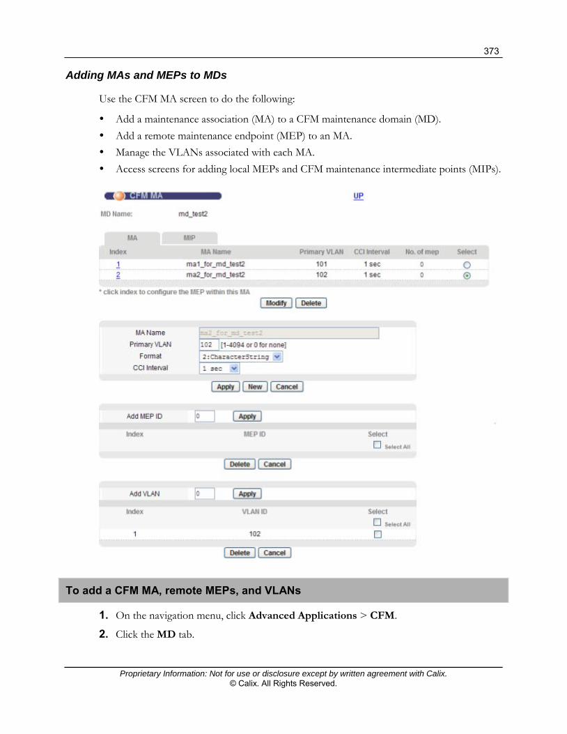
373
Proprietary Information: Not for use or disclosure except by written agreement with Calix. © Calix. All Rights Reserved.
Adding MAs and MEPs to MDs
Use the CFM MA screen to do the following:
Add a maintenance association (MA) to a CFM maintenance domain (MD). Add a remote maintenance endpoint (MEP) to an MA. Manage the VLANs associated with each MA. Access screens for adding local MEPs and CFM maintenance intermediate points (MIPs).
To add a CFM MA, remote MEPs, and VLANs
1. On the navigation menu, click Advanced Applications > CFM.
2. Click the MD tab.

374
Proprietary Information: Not for use or disclosure except by written agreement with Calix. © Calix. All Rights Reserved.
3. In the MD list at the bottom of the screen, click the link to the MD under the Index column.
The MD name displays at the top of the screen for reference.
4. To add a new MA to the MD, do the following:
a. If the MA Name box displays an existing association, below the CC Interval list, click New to clear it.
b. In the MA Name box, type the name to identify the MA (up to 45 characters).
c. In the Primary VLAN box, type a VLAN ID (1 to 4094) to use a primary VLAN, or type 0 to use untagged CFM frames.
If you specify 0, the following limitations apply:
No VLAN will be served CFM frames by the MD. Only untagged CFM frames will be served.
The MD specified must be set to the lowest level (0).
Only one MA can be set up to use untagged CFM frames.
d. In the Format list, select the format to be carried in the MA field of the CFM header (primary VLAN ID or character string).
Note: CFM devices in the same network should use the same format.
e. In the CC Interval list, select the continuity check message initiation interval to apply when CCI is enabled for the MEPs: 1 second, 10 seconds, 60 seconds (1 min), or 10 minutes. By default, 1 second is used.
f. Below the CC Interval list, click Apply.
The new MA displays in the list at the top of the screen.
5. To add a remote MEP ID to the MA, in the MEP ID box, type the MEP identifier (1 to 8191) to use. Below the MEP ID box, click Apply.
The new remote MEP displays in the list below the MEP ID box.
Note: To define a local MEP, see the procedure, "To add or modify a local MEP" below.
6. To add a VLAN to the MA, at the bottom of the screen, in the Add VLAN box, type the VLAN ID (1 to 4094) to add. Below the Add VLAN box, click Apply.
The VLAN displays in the list below the Add VLAN box.
7. If you are finished making changes in the CFM MA screen, click the UP link at the top right of the screen to return to the CFM MD screen.

375
Proprietary Information: Not for use or disclosure except by written agreement with Calix. © Calix. All Rights Reserved.
To modify CFM MA, remote MEP, or VLAN settings
Note: To define a local MEP, see the procedure below, "To add or modify a local MEP."
1. Pull up the CFM MA on screen:
a. On the navigation menu, click Advanced Applications > CFM.
b. Click the MD tab.
c. In the MD list at the bottom of the screen, click the link to the MD under the Index column.
The MD name displays at the top of the screen for reference.
d. In the MA list at the top of the screen, under the Select column, select the radio button for the MA you are modifying.
e. Below the maintenance association list, click Modify.
2. To modify the MA's primary VLAN, CFM header format, or CCI interval for the MA, type or select the new settings to use. Below the CCI Interval list, click Apply.
3. To add or modify a MEP, do one of the following:
To add a remote MEP, in the MEP ID box, type the MEP identifier (1 to 8191) to use. Below the MEP ID box, click Apply.
To remove a remote MEP from the MA, in the MEP list in the middle of the screen, select the check box(es) for the MEP(s) you are deleting, and then click Delete.
The revised MEP list display below the MEP ID box.
4. To add or modify a VLAN, do one of the following:
To add a VLAN, in the Add VLAN box, type the VLAN ID (1 to 4094) to add. Below the Add VLAN box, click Apply.
To remove a VLAN from the MA, in the VLAN list at the bottom of the screen, select the check box for each VLAN you are deleting, and then click Delete.
5. If you are finished making changes in the CFM MA screen, the click the UP link at the top right of the screen to return to the CFM MD screen.
To add or modify a local MEP
1. Pull up the CFM MA on screen:
a. On the navigation menu, click Advanced Applications > CFM.
b. Click the MD tab.
c. In the MD list at the bottom of the screen, click the link to the MD under the Index column.
The CFM MA screen opens.

376
Proprietary Information: Not for use or disclosure except by written agreement with Calix. © Calix. All Rights Reserved.
d. In the MA list at the top of the screen, under the Index column, click the link for the MA for which you are adding or modifying MEPs.
The CFM MEP screen opens and the MD and MA names display for reference.
At the bottom of the screen, in the MEP list, any local MEPs that are associated with the device display.
2. To create a new local MEP, type or select the settings on screen:
a. Under the MAC Address box, click New.
b. In the Endpoint ID box, type the MEP identifier (1 to 8191) to use.
c. In the port list, select the subscriber, Ethernet, or management port on which to create the local MEP.
d. In the Direction list, select the SAP direction. Note the following:
In the up direction, CFM PDUs are sent towards the relay entity, and then forwarded to other bridge ports.
In the down direction, CFM PDUs are sent out the bridge port to the network.
e. In the Priority list, select the priority carried in the CFM PDUs sent out from this endpoint (0 to 7).
f. Select the CCI Enabled check box to issue a continuity check message, or leave the check box clear to leave off continuity check messages.

377
Proprietary Information: Not for use or disclosure except by written agreement with Calix. © Calix. All Rights Reserved.
g. In the Alarm Time box, optionally change the least preset time before an alarm is issued (25 to 100, in 0.1-second increments). The default value is 25.
h. In the Reset Time box, optionally change the least preset time before the alarm state is reset (25 to 100, in 0.1-second intervals). The default is 100.
i. In the MAC Address box, type the MAC address for the MEP to use. By default, the MAC address of the management interface displays in the field.
j. Below the MAC Address box, click Apply to save the settings.
3. To modify a local MEP, after opening the CFM MA screen, do the following:
a. In the MEP list at the bottom of the screen, under the Select column, select the radio button for the MEP you are editing. Below the MEP list, click Modify.
The settings for the selected MEP display on screen with Endpoint ID field disabled.
b. Follow Steps 5c through 5j to modify the default settings.
4. To delete a local MEP, in the MEP list at the bottom of the screen, under the Select column, select the radio button for the MEP you are deleting. Below the MEP list, click Delete.
5. If you are finished adding and modifying local MEPs, click the UP link at the top right of the screen to return to the CFM MA screen.
6. In the CFM MA screen, click the UP link at the top right of the screen to return to the CFM MD screen.
To add MIPs to an MD
1. On the navigation menu, click Advanced Applications > CFM.
2. Click the MD tab.
3. In the MD list at the bottom of the screen, click the link to the MD under the Index column to open the CFM MA screen.
4. Click the MIP tab to open the CFM MIP screen.
The MD name displays at the top of the screen for reference.
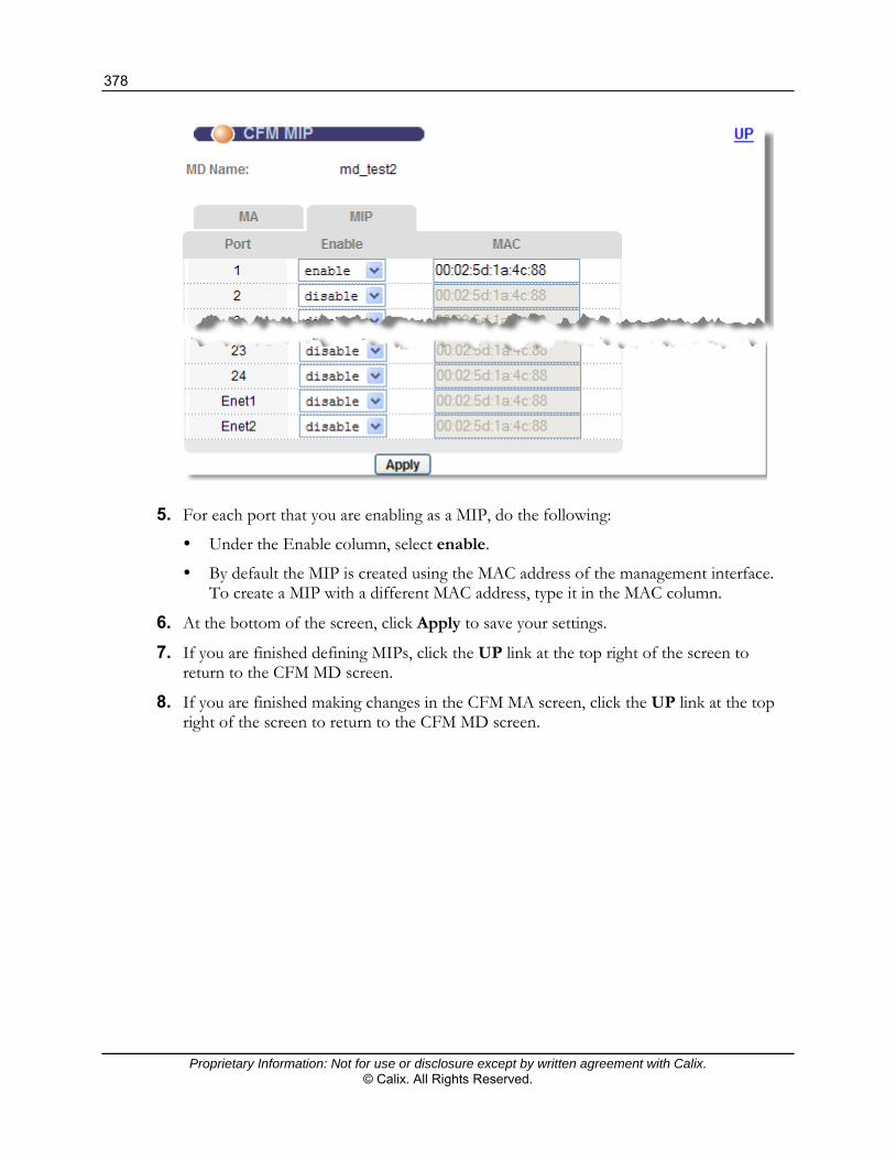
378
Proprietary Information: Not for use or disclosure except by written agreement with Calix. © Calix. All Rights Reserved.
5. For each port that you are enabling as a MIP, do the following:
Under the Enable column, select enable.
By default the MIP is created using the MAC address of the management interface. To create a MIP with a different MAC address, type it in the MAC column.
6. At the bottom of the screen, click Apply to save your settings.
7. If you are finished defining MIPs, click the UP link at the top right of the screen to return to the CFM MD screen.
8. If you are finished making changes in the CFM MA screen, click the UP link at the top right of the screen to return to the CFM MD screen.

379
Proprietary Information: Not for use or disclosure except by written agreement with Calix. © Calix. All Rights Reserved.
Enabling Loopback Responses (LBRs)
Use the CFM LBR screen to enable (or disable) loopback responses (LBRs) for individual subscriber and Ethernet ports.
To enable (or disable) LBRs
1. On the navigation menu, click Advanced Applications > CFM.
2. Click the LBR tab.
3. To the right of each subscriber or Ethernet port for which you are enabling (or disabling) LBRs, select enable (or disable).
4. At the bottom of the screen, click Apply to save your settings.

380
Proprietary Information: Not for use or disclosure except by written agreement with Calix. © Calix. All Rights Reserved.
Viewing MEP and MIP Statistics
After creating CFM maintenance endpoints (MEPs) and maintenance intermediate points (MIPs), use the MEP Status and MIP Status screen to view statistics for individual endpoints and intermediate points:
For MEPs you can view statistics for continuity check messages (CCMs), loopback messages (LBMs), Loopback Responses (LBMs), Linktrace messages (LTMs), and Linktrace responses (LTRs).
For MIPs you can view the number of loopback messages (LBMs) received and Loopback Responses (LBMs) sent and the number of Linktrace messages (LTMs) received and Linktrace responses (LTRs) sent.
To view MEP statistics
1. On the navigation menu, click Advanced Applications > CFM.
2. Click the MEP Status tab.
For long MEP lists, you can filter by MD, MA, and MEP ID by selecting the objects you have pre-defined and clicking Load, or you can scroll through the list screen-by-screen by clicking Previous and Next.
3. To view a MEP status, click the link under the Index column corresponding to the MEP.

381
Proprietary Information: Not for use or disclosure except by written agreement with Calix. © Calix. All Rights Reserved.
4. To return to the CFM MEP Status screen, click the UP link at the top right of the screen.
To view MIP statistics
1. On the navigation menu, click Advanced Applications > CFM.
2. Click the MIP Status tab.
If you have more than one MD defined, you can filter the MIP list by selecting an MD you have pre-defined, or you can scroll through the list screen-by-screen by clicking Previous and Next.

382
Proprietary Information: Not for use or disclosure except by written agreement with Calix. © Calix. All Rights Reserved.
3. To view statistics for a MIP, click the link under the Index column corresponding to the MIP.
4. To return to the CFM MIP Status screen, click the UP link at the top right of the screen.
Performing a CFM Loopback Test
Use the CFM Loopback screen to perform loopback tests.
Note: Before performing a loopback test, use the procedures in this section to define the CFM maintenance domain (MD), maintenance association (MA), and maintenance endpoints (MEPs) and intermediate points (MIPs) that you are using for the test.
A CFM loopback test can target a MAC address or a Remote Maintenance Endpoint ID (RMEPID) that is configured as part of the CMF network.

383
Proprietary Information: Not for use or disclosure except by written agreement with Calix. © Calix. All Rights Reserved.
To perform a CFM loopback test
1. On the navigation menu, click Advanced Applications > CFM.
2. Click the Loopback tab.
3. In the MD and MA lists, select the maintenance domain and maintenance association that you have previously defined to use for the test.
4. In the MEP ID list, select the MEP from which to issue the test.
5. To the right of Target, select the radio button for the entity you are targeting as the other endpoint for the test:
To target a MAC address, in the MAC box, type the MAC address.
To target a remote MEP that has been defined on a different device, select the radio button to the left of the RMEPID box, and then type the endpoint ID.
6. In the Length box, specify the loopback message length, in bytes.
7. In the Count box, specify the count.
8. In the Timeout box, specify the timeout.
9. At the bottom of the screen, click Test and view the results in the monitoring area of the screen.
10. To display loopback data, click Get Loopback Data.
Performing a CFM Linktrace Test
Use the CFM Linktrace screen to perform linktraces.
Note: Before performing a linktrace, use the procedures in this section to define the CFM maintenance domain (MD), maintenance association (MA), and maintenance endpoints (MEPs) and intermediate points (MIPs) that you are using for the test.
A CFM linktrace can target a Remote Maintenance Endpoint ID (RMEPID) or MAC address that is configured as part of the CMF network.

384
Proprietary Information: Not for use or disclosure except by written agreement with Calix. © Calix. All Rights Reserved.
To perform a CFM linktrace
1. On the navigation menu, click Advanced Applications > CFM.
2. Click the Linktrace tab.
3. In the MD and MA lists, select the maintenance domain and maintenance association that you have previously defined to use for the linktrace.
4. In the MEP ID list, select the MEP from which to issue the linktrace.
5. To the right of Target, select the radio button for the entity you are targeting as the other endpoint for the linktrace:
To target a remote MEP that has been defined on a different device, in the RMEPID box, then type the endpoint ID.
To target a MAC address, select the radio button to the left of MAC, and then in the MAC box, type the MAC address.
6. In the TTL box, specify the TTL value (1 to 64) to be carried in the outgoing trace packet.
7. At the bottom of the screen, click Test and view the results in the monitoring area of the screen.
8. To display loopback data, click Get Linktrace Data.

385
Proprietary Information: Not for use or disclosure except by written agreement with Calix. © Calix. All Rights Reserved.
MAC Table
The MAC table lists device MAC addresses dynamically learned by the E3-12C/E5-120/E5-121. The MAC table contains the following information for each MAC address:
The port upon which Ethernet frames were received from the device To which VLAN groups the device belongs (if any) To which channel it is connected (for devices connected to DSL ports)
The device uses the MAC table to determine how to forward frames, as shown in the following graphic:
Forward to all ports except the incoming one
Forward to outgoing port
Is the destination MAC address in the MAC table?
Is the outgoing port different from the incoming port?
Filter this frame
No
No
Yes
Yes
The device examines a received frame and learns the port on which this source MAC address came.
The device checks to see if the frame's destination MAC address matches a source MAC address already learned in the MAC table.
If the device has already learned the port for this MAC address, then it forwards the frame to that port.
If the device has not already learned the port for this MAC address, then the frame is flooded to all ports. Too much port flooding leads to network congestion.
If the device has already learned the port for this MAC address, but the destination port is the same as the port it came in on, then it filters the frame.

386
Proprietary Information: Not for use or disclosure except by written agreement with Calix. © Calix. All Rights Reserved.
MAC Table Screen
To open the Mac Table screen
On the navigation menu, click Management > MAC Table.
The following table describes the elements of the MAC Table screen:
Element Description
Show Port In the Show Port list box, select a port to display learned MAC addresses (or click All to display all of them).
Index The number of the MAC table entry.
Port The port associated with the MAC address.
VID The VLAN ID.
MAC The MAC address of the device associated with this incoming frame.
Refresh Click Refresh to update the list of dynamically learned MAC addresses.
Flush Click Flush to remove all of the dynamically learned MAC address entries from the MAC table.

387
Proprietary Information: Not for use or disclosure except by written agreement with Calix. © Calix. All Rights Reserved.
ARP Table
Address Resolution Protocol (ARP) is a protocol for mapping an IP address to a physical Media Access Control (MAC) address on the local area network.
An IP (version 4) address is 32 bits long. In an Ethernet network, MAC addresses are 48 bits long. The ARP table maintains an association between each MAC address and its corresponding IP address.
How ARP Works
When an incoming packet destined for a host device on a local area network arrives at the device, the device's ARP program looks in the ARP table and, if it finds the address, sends the packet to the device.
If no entry is found for the IP address, ARP broadcasts the request to all the devices on the network. The device fills in its own MAC and IP address in the sender address fields, and puts the known IP address of the target in the target IP address field. In addition, the device puts all ones in the target MAC field (FF.FF.FF.FF.FF.FF is the Ethernet broadcast address).
The replying device (which is either the device being sought or the router that knows the way) replaces the broadcast address with the target's MAC address, swaps the sender and target pairs, and unicasts the answer directly back to the requesting machine. ARP updates the ARP table for future reference and sends the packet to the MAC address that replied.

388
Proprietary Information: Not for use or disclosure except by written agreement with Calix. © Calix. All Rights Reserved.
ARP Table Screen
The ARP table can hold up to 500 entries.
To open the ARP Table screen
On the navigation menu, click Management > ARP Table.
The following table describes the elements of the ARP Table screen:
Element Description
Flush Click Flush to remove all of the entries from the ARP table.
Total x ARP Entries The number of entries in the ARP table.
Page x of x Identifies which page of information is displayed and the total number of pages of information.
Index The ARP table entry number.
IP Address The learned IP address of a device connected to a port.
MAC Address The MAC address of the device with the listed IP address.
Previous Page Click Previous Page to display the preceding screen of information.
Next Page Click Next Page to display the next screen, if the information cannot be shown in one screen.

389
Proprietary Information: Not for use or disclosure except by written agreement with Calix. © Calix. All Rights Reserved.
Maintenance Features
This section describes the following E3-12C/E5-120/E5-121 maintenance topics:
Rebooting the system Loading (restoring) the factory default configuration
To open the E3-12C/E5-120/E5-121 maintenance screen
On the navigation menu, click Management > Maintenance.
Reference topics and publications
Performing Backup and Restore Operations (on page 47) For instructions on how to perform a firmware upgrade in the Configurator user
interface, see Upgrading System Software (on page 43). For instructions on how to perform a firmware upgrade in the Calix Management System
(CMS), see the Calix Management System (CMS) Guide. For information about uploading and downloading files using FTP commands, see
"Firmware and Configuration File Maintenance" in the Calix E3-12C/E5-120/E5-121 CLI Reference.
Rebooting the System
Use this function to restart the device without physically turning the power off. Rebooting does not affect the system configurations.
To reboot the system
1. On the navigation menu, click Management > Maintenance > Reboot System.

390
Proprietary Information: Not for use or disclosure except by written agreement with Calix. © Calix. All Rights Reserved.
2. In the Set Reboot Timer box, type the number of seconds (5 to 1800) for the reboot timer (use 0 to reboot immediately).
3. Click Reboot.
4. Click OK to reboot the system.
5. Click OK.
It takes up to two minutes for the device to restart (does not affect the device's configuration).
If you set the reboot timer, you can cancel the reboot at any time before the timer runs out by clicking Cancel Reboot Timer.

Proprietary Information: Not for use or disclosure except by written agreement with Calix. © Calix. All Rights Reserved.
Appendix A
Resetting the Defaults
If you lock yourself (and others) from the E3-12C/E5-120/E5-121, you will need to reload the factory-default configuration file. Uploading the factory-default configuration file replaces the current configuration file with the factory-default configuration file. This means that you will lose all previous configurations and the speed of the console port will be reset to the default of 9600 bps with 8 data bit, no parity, one stop bit and flow control set to none. The user name will be reset to “admin” and the password will be reset to “1234” with the IP address to 192.168.1.1.
Load Factory Defaults Using the Web Interface
Use this function to clear all device configuration information you configured and return to the factory defaults.
Warning: Restoring the default configuration deletes all the current settings. Calix recommends that you back up the configuration file before restoring the default configuration.
To restore the default configuration
1. On the navigation menu, click Management > Maintenance > Restore Default Configuration. A confirmation screen opens.

392
Proprietary Information: Not for use or disclosure except by written agreement with Calix. © Calix. All Rights Reserved.
2. Click OK to begin resetting all device configurations to the factory defaults. It may take up to two minutes to restore the settings.
Note: The system restarts once the defaults are restored.
3. If you want to access the Web Configurator again, you may need to change the IP address of your computer to be in the same subnet as that of the default device IP address (192.168.1.1).
Resetting the Defaults via CLI Command
If you know the password, you can reload the factory-default configuration file with a Command Line Interface (CLI) command.
To reload the factory-default configuration file
1. Connect to the console port using a computer with terminal emulation software.
2. Enter your password.
3. Enter config restore.
4. Enter y at the question “Do you want to restore default ROM file (y/n)?”
The E3-12C/E5-120/E5-121 restarts.
The following is an example of resetting the switch via command:
ras> config restore System will reboot automatically after restoring default configuration. Do you want to proceed (y/n)? > restoring configuration... saving configuration to flash...
The E3-12C/E5-120/E5-121 is now re-initialized with a default configuration file including the default user name of “admin” and the default password of “1234”.

393
Proprietary Information: Not for use or disclosure except by written agreement with Calix. © Calix. All Rights Reserved.
Uploading the Default Configuration File
If you forget your password or cannot access the E3-12C/E5-120/E5-121, you will need to reload the factory-default configuration file. Uploading the factory-default configuration file replaces the current configuration file with the factory-default configuration file. This means that you will lose all previous configurations and the speed of the console port will be reset to the default of 9600 bps with 8 data bit, no parity, one stop bit and flow control set to none. The password will also be reset to “1234” with the IP address of 192.168.1.1.
Important: Uploading the factory default configuration file erases the entire E3-12C/E5-120/E5-121 configuration.
Obtain the default configuration file, unzip it and save it in a folder. Use a console cable to connect a computer with terminal emulation software to the E3-12C/E5-120/E5-121 console port. Turn the E3-12C/E5-120/E5-121 off and then on to begin a session. When you turn on the E3-12C/E5-120/E5-121 again you will see the initial screen. When you see the message "Press any key to enter Debug Mode within 3 seconds", press any key to enter debug mode.
To upload the configuration file
1. Type atlc after the Enter Debug Mode message.
2. Wait for the Starting XMODEM upload message before activating XMODEM upload on your terminal.
3. Click Transfer, then Send File to display the following screen. This is an example Xmodem configuration upload using HyperTerminal.
4. Type the configuration file's location, or click Browse to search for it. Select the 1K Xmodem protocol. Click Send.
5. After a successful configuration file upload, type atgo to restart the E3-12C/E5-120/E5-121.
The E3-12C/E5-120/E5-121 is now re-initialized with a default configuration file including the default password of “1234”.

394
Proprietary Information: Not for use or disclosure except by written agreement with Calix. © Calix. All Rights Reserved.
E3-12C/E5-120/E5-121 Default Settings
The following table shows the default configuration settings for the E3-12C/E5-120/E5-121.
Administration Default Settings
Default In-Band IP Address 192.168.1.1
Default In-Band Subnet Mask 255.255.255.0 (24 bits)
Default Out-of-Band IP Address 192.168.0.1
Default Out-of-Band Subnet Mask 255.255.255.0 (24 bits)
Default User Name admin (case sensitive)
Default Password 1234
Default Console Port Settings VT100 terminal emulation, 9600 bps, No parity, 8 data bits, 1 stop bit, and no flow control
VLAN Default Settings
VLAN ID Upstream Settings Downstream Settings
1 - MgmtVlan Fixed for Ethernet ports Untagged
2 - VoIPVlan Fixed for Ethernet ports Untagged
3 - DEFAULT Fixed for VDSL ports Untagged
VDSL Default Settings
Name DEFVAL
Latency Mode Interleave
Upstream Settings Downstream Settings
Maximum Rate 45056 Kbps 100032 Kbps
Minimum Rate 192 Kbps 192 Kbps
Interleave (latency) Delay 8 ms 8 ms
Maximum Signal to Noise Ratio 31 dB 31 dB
Minimum Signal to Noise Ratio 0 dB 0 dB
Target Signal to Noise Ratio 6 dB 6 dB
Rate Adaptation Mode Startup Startup
Ham Band Plan 0x0000
Custom Notch1 Start: 0 (kHz) Stop: 0 (kHz)
Custom Notch2 Start: 0 (kHz) Stop: 0 (kHz)
VDSL2 Profile 6 (17a)
Minimum Downstream INP 5 (0.5 DMT symbol)
Minimum Upstream INP 5 (0.5 DMT symbol)
Limit PSD Mask 2
VDSL Option 0x00000000
enable us bitswaps
enable ds bitswaps
disable UPBO
disable DPBO
ESEL 0 (0.0 dB)
UPBOESEL 0 (0.0 dB)

395
Proprietary Information: Not for use or disclosure except by written agreement with Calix. © Calix. All Rights Reserved.
DPBOEPSD Break Point, Tone Index, (Frequency), PSD level
0, 1, (4.3125 kHz), -60.0 dBm
1, 32, (138.0 kHz), -60.0 dBm
2, 33, (142.3125 kHz), -40.0 dBm
3, 255, (1099.6875 kHz), -40.0 dBm
4, 376, (1595.6250 kHz), -50.0 dBm
5, 511, (2203.6875 kHz), -51.5 dBm
6, 512, (2208.0 kHz), -80.0 dBm
DPBOESCMA 256 (scalar value: 0.0)
DPBOESCMB 512 (scalar value: 1)
DPBOESCMC 256 (scalar value: 0)
DPBOMUS 180 (-90.0 dBm/Hz)
DPBOFMIN 0 (0.0 kHz)
DPBOFMAX 511 (2203.6875 kHz)
UPBO Parameters A B
Upstream Band 1 5650 (56.50 dBm/Hz) 1019 (10.19 dBm/Hz)
Upstream Band 2 5650 (56.50 dBm/Hz) 614 (6.14 dBm/Hz)
Upstream Band 3 0 (0.0 dBm/Hz) 0 (0.0 dBm/Hz)
Virtual Channel Default Settings Note: The E3-12C/E5-120/E5-121 VDSL ports’ PVCs use ATM Adaptation Layer (AAL) 5.
Super channel: Enabled
VPI: 10
VCI: 43
VC Profile: DEFVAL (factory default)
Multiplexing: LLC-based
Default IGMP Profile Settings The AllVideoService IGMP profile is assigned to all VDSL ports by default. It allows a port to join all multicast IP addresses (224.0.0.0 through 239.255.255.255).
VoIP SIP Profile Default Settings (E3-12C/E5-121 Only)
Name DEFVAL
SIP server domain name 0.0.0.0
SIP registrar server domain name 0.0.0.0
SIP proxy server domain name 0.0.0.0
SIP server port number 5060
SIP registrar server port number 5060
SIP proxy server port number 5060
URI type SIP
IEEE 802.1p tag 7
DSCP tag 48
Keep alive off
PRACK off
VoIP DSP Profile Default Settings
Name DEFVAL
Codec G.711µ
Min-delay 30 ms
Max-delay 120 ms

396
Proprietary Information: Not for use or disclosure except by written agreement with Calix. © Calix. All Rights Reserved.
Echo tail 32 ms
VoIP SIP Call Service Profile
Name DEFVAL
Password none
Numbering plan off
Call holding on
Call waiting on
Call transferring on
CLIP on
CLIR on
Conferencing off
DND on
DTMF bypass
Fax G.711
VoIP Default Regional Settings
Country code USA (0)
VoIP Default H.248 Profile Settings
mgc-ic/domain name 0.0.0.0
mgc-port 2944
mgc-ic2/domain name off
transport udp
encoding long
P-bit 7
DSCP 48
phyprefix, start-num, and suffix-len TP, 1, 0
ephprefix, start-num, and suffix-len RTP, 1, 0
softswitch metaswitch
vbd off
foreover off
RTP start and end ports 60000, 65000