cadman doda · 3. before separating the extension from the volute, mark the two (2) parts as a...
TRANSCRIPT
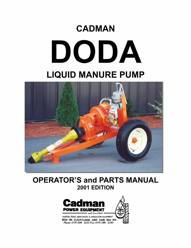
CADMAN
DODA LIQUID MANURE PUMP
OPERATOR’S and PARTS MANUAL 2001 EDITION


07/23/10
INDEX
When Applying Liquid Manure .............................................................................................. 1
Introduction .................................................................................................................................. 2
Safety .............................................................................................................................................. 3
Operation ...................................................................................................................................... 4
Maintenance ................................................................................................................................. 5
Daily
Weekly
Annually
Before Storing (After Use)
Troubleshooting & Remedy ...................................................................................................... 5
Seal Replacement Procedure
Pump Disassembly ....................................................................................................... 7
Pump Reassembly ...................................................................................................... 10
Primer Pump Service
Disassembly ............................................................................................................... 12
Reassembly ................................................................................................................. 12
Notes ............................................................................................................................................. 14
Parts Section Index ................................................................................................................... 15

1
WHEN APPLYING LIQUID MANURE . . . Environmental concerns seem to be driving legislative agendas in many agricultural areas across the continent. Current and pending laws in many agricultural regions of North America are changing the ways in which the agricultural community is expected to manage their liquid animal waste products. The changes in legislation typically target two main issues; run-off prevention during and after application and soil nutrient loading. Run off seems to be the largest concern with nutrient application. Run off may result from several different factors, most of which are controllable. These factors include; exceeding the soil intake rate; nutrient application on steep grades; high application amounts; leaking mainline fittings and seals; sudden rainfall during or immediately after application; ground frost; etc. Constant watch must be kept and immediate action taken when necessary to prevent run off from occurring. Soil nutrient loading depends on many variables. Some of these variables (but certainly not all) are soil type, type of crop being grown in the irrigated area, application timing, nutrient value of the material being applied (nutrient value should be assessed at the time of application as it can change throughout the year), etc. Soil type will determine the intake rate at which liquid may be applied. Cultivation of the field just prior to application can improve the intake rate of some soils. Great potential benefit lies in using the nutritional value of the product being applied to replace some or all of the traditional chemical fertilizer used. Application timing and amount are important considerations. Soil analysis taken prior to planting and during the growth periods of the crop will help determine if there is room for further application amounts to be added prior to crop maturity. A total management plan should include provisions to end the crop season without surplus nutrients left as residual. These excess nutrients typically end up in the ground water supply. Local colleges, universities and agricultural extension services are usually a good source of information. They can usually help you determine an application program that prevents soil nutrient overload due to excess application.
Cadman Power Equipment Limited cannot possibly provide up-to-date recommendations with regard to the legal obligations you must deal with in your particular area. However, as a manufacturer of equipment used in nutrient application (liquid manure, milk house run-off, etc.), we feel it necessary to make you aware that the municipal, regional and state governing bodies in your area may have recently enacted new legislation or revised existing legislation with regard to nutrient handling practices and procedures. It is your responsibility to make yourself aware of and abide by the current legislation in your area. Please take the time to contact your local agricultural representative to obtain the latest information regarding legal nutrient application and handling.

2
INTRODUCTION
Your new Doda Pump is an open impeller centrifugal pump capable of
pumping various types of fluids and slurries at pressures in excess of 160 psi. It
is of rugged construction and combines several innovative features.
Your pump has a mechanical seal to provide easy priming and positive
leak-proof sealing. The standard seal is a tungsten and ceramic unit which
provides good life in most pumping situations provided proper care is taken in
using the pump.
Unlike many other pump manufacturers, Doda protects the pump gear
case by providing an air gap between the pump case and the gearbox. This air
gap prevents gearbox contamination in the event of a seal failure.
Static cutter blades will mulch any organic material passing through the
pump. The result is greatly reduced chance of nozzle plugging. The mounting of
the blades to the inside of the pump casing provides this benefit with no increase
in power consumption. These blades are designed to break off should
something solid come in contact with them. Replacement blades are available
from your Cadman Power Equipment Dealer.
The ultimate obtainable pump pressure depends on several inter-related
factors or conditions such as discharge volume, pump impeller speed and net
suction pressure.

3
P.T.O. PUMP SAFETY
ALWAYS position your pump and tractor on firm level ground. Block the
tractor wheels to prevent the tractor wheels to prevent the
tractor from rolling during operation.
ALWAYS lock the pump cart draw pin in place to prevent accidental
separation of the pump and tractor.
ALWAYS check the yoke locks of the P.T.O. shaft to ensure both ends
are secured to the pump and the tractor, and no chance of
separating exists.
ALWAYS attach the chain on the P.T.O. shaft guard to prevent it from
rotating during operation. (Make sure to lubricate the P.T.O.
shaft guard bushings)
ALWAYS stay clear of high pressure discharge lines especially during
initial pressurization.
NEVER use a pump or P.T.O. shaft that is missing the guards.
4
OPERATION
1. Connect the Doda P.T.O. pump to a suitable tractor using a locking draw
pin to prevent accidental pump-tractor separation. If the tractor has a
“stepped” drawbar, set the drawbar so the pump trailer is as level as
possible.
2. Install the P.T.O. drive shaft between the pump and tractor. Ensure that
the yokes are securely locked to the mating shafts.
3. Attach the P.T.O. shaft guard retaining chain to the pump guard to prevent
the shaft shield from rotating during operation.
4. Check the oil level in the pump gear case. The dipstick has two (2) marks
on it. The lower mark indicates “Full” when the pump is cold. The upper
mark indicates “Full” when the pump is hot. Use which ever is appropriate.
Add oil if necessary. (85 W 140)
5. Couple the suction assembly to the rear of the pump.
6. Couple the discharge plumbing to the side of the pump.
NOTE: Omit steps 7, 8 & 9 if using the Doda pump as a booster pump.
Positive pressure in the primer circuit will damage the primer.
7. Close the discharge valve.
8. Open the valve in the primer line.
9. Operate the hand primer to evacuate all the air from inside the suction
assembly and pump case. Listen carefully for air leaks which will prevent
priming of the pump. Close the valve in the primer line as soon as fluid
appears in the primer hose.
10. With the tractor running near idle, engage the P.T.O. drive only AFTER
the pump has been primed. Running the pump dry will destroy the pump
seal, in less than one minute.
11. Open the discharge valve slowly to allow fluid to flow. BEFORE raising
the tractor RPM level, allow adequate time for ALL the air to be purged
from the system. AFTER all the air has cleared the system, gradually
increase tractor P.T.O. speed until the desired operating pressure is
attained.
12. Make a visual check of the pump site to ensure that:
the pump is running smoothly without excess vibration
the suction screen is adequately submerged and no suction vortex
is visible on the fluid surface.
the discharge fittings appear secure
there are no leaks

5
MAINTENANCE
DAILY (Before Each Use)
- Check the oil level in the gear case. Replenish with 85 W 140 as required.
- Drain primer surge tank. WEEKLY
- Grease the P.T.O. shaft u-joints and shield bushings. ANNUALLY
- Change gear case oil. BEFORE STORING (After Use)
- Flush pump with clear water to clear corrosive fluids or slurries.
- Drain pump volute and primer surge tank.
- Lubricate the discharge valve to prevent seizing during idle periods.
- Coat gearbox input shaft and P.T.O. shaft yoke bores with grease to prevent corrosion.
The above maintenance will ensure trouble free use of your Doda Pump. Due
to the harsh environment these pumps typically operate in, these maintenance items should be carried out without fail.
TROUBLE SHOOTING AND REMEDY
CONDITION POSSIBLE CAUSE SOLUTION (s)
Pump will not prime
drain plug missing
suction screen or hose is plugged
air leak in the suction assembly
air is leaking into the pump through the pump seal
air is leaking into the pump through the discharge valve
primer pump not functioning properly
install plug (s)
clear hose or screen
check suction connection at the pump
check for leaks in the suction assembly
repair or replace defective parts
seal has failed
replace seal
clean and seal the discharge valve
service primer pump

6
CONDITION POSSIBLE CAUSE SOLUTION (s)
Pump will not prime
(cont’d)
primer line or surge tank plugged clean as required
Pump will not prime
air is leaking into the pump past the seal when P.T.O. is engaged
air is trapped in the pump case
discharged valve plate is stuck closed
suction lift is too high
slurry is too thick
replace the seal
operate hand primer to exhaust air
service valve
move pump closer to fluid surface
add water to thin consistency
Pump will not build pressure
Suction hose partially blocked
Suction has a minute (tiny) air leak
Large object is partially blocking impeller
Discharge valve only partially opened
Suction assembly is too small for volume being pumped
P.T.O. speed too slow
Seal damaged allowing air entry at high rpm’s
Suction lift too high
Clear blockage
Repair or replace leaking component
Remove object from the pump
Open valve
Replace with larger assembly
Check shaft rpm under loaded conditions
Replace seal
Re-position pump closer to fluid surface
Pump vibrates excessively
pump input shaft is not parallel to the tractor output shaft
pump is not in line with the tractor
P.T.O. shaft angle is too severe
P.T.O. shaft u-joint has failed
foreign object has lodged in the pump impeller
pump cart tires are soft
adjust tractor drawbar height to level the pump frame
straighten pump position behind the tractor
correct shaft angle
replace u-joint
remove objects to restore balance
add air
block pump frame
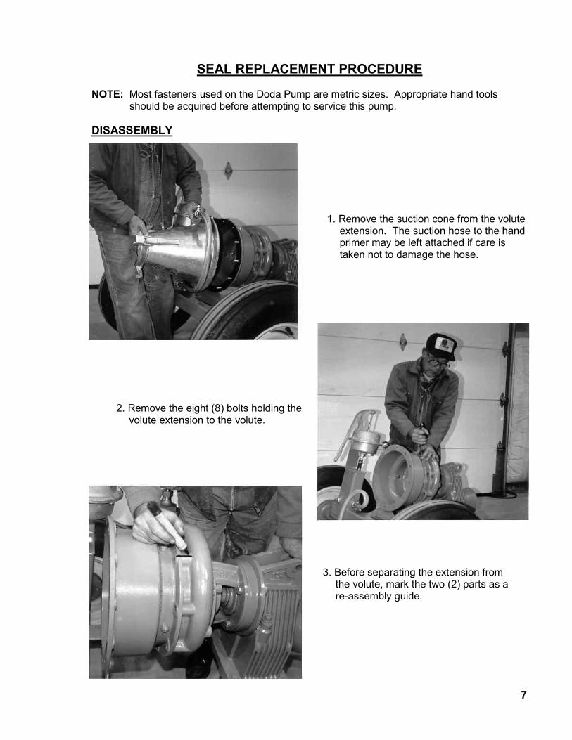
SEAL REPLACEMENT PROCEDURE NOTE: Most fasteners used on the Doda Pump are metric sizes. Appropriate hand tools
should be acquired before attempting to service this pump.
DISASSEMBLY
1. Remove the suction cone from the volute extension. The suction hose to the hand primer may be left attached if care is taken not to damage the hose.
2. Remove the eight (8) bolts holding the volute extension to the volute.
3. Before separating the extension from the volute, mark the two (2) parts as a re-assembly guide.
7

8
4. Using a block and hammer, carefully work around the volute extension until the two pieces separate. The impeller cover should be left attached to the volute extension
5. Once the extension seal is broken, remove the extension from the volute.
6. Remove the impeller nut.

7. Install two (2) of the bolts from the suction cone into the impeller. Tighten each 1/2 turn at a time until the impeller separates from the shaft.
8. After the impeller is removed, the volute may be removed from the gearbox extension. Remove the four (4) nuts (arrows) to remove the volute. Once the extension seal is broken, remove the extension from the volute.
9. Remove the glad plate from the volute. Remove the impeller nut.
10. Old seal components are stationary seal face (A), rotating seal face (B), spring and spring washer.Remove the glad plate from the volute. Remove the impeller nut.
9
10
DODA RE-ASSEMBLY After thoroughly cleaning the pump components to ensure ease of assembly and proper parts fit, re-assembly may begin. 1 Assemble the gland plate to the volute using silicone gasket maker to seal the mating
surfaces.
2 Assemble the volute to the gearbox spacer using silicone gasket maker under the bolt heads to seal them.
3 Lightly oil the o-ring of the stationary seal face and install into the gland plate. Use only finger pressure to push the seal face into place.
NOTE: Only one side of the stationary seal face is ground smooth. The un-ground face is
marked with four (4) pen marks. Be sure that the unmarked surface is in the gland plate.
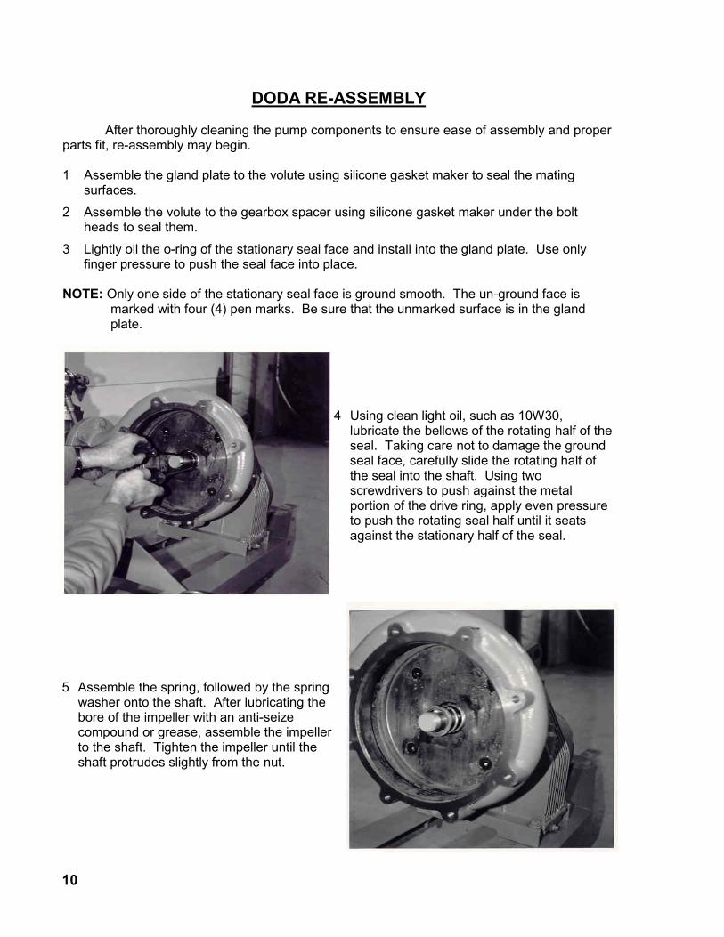
4 Using clean light oil, such as 10W30, lubricate the bellows of the rotating half of the seal. Taking care not to damage the ground seal face, carefully slide the rotating half of the seal into the shaft. Using two screwdrivers to push against the metal portion of the drive ring, apply even pressure to push the rotating seal half until it seats against the stationary half of the seal.
5 Assemble the spring, followed by the spring washer onto the shaft. After lubricating the bore of the impeller with an anti-seize compound or grease, assemble the impeller to the shaft. Tighten the impeller until the shaft protrudes slightly from the nut.

11
NOTE: Impeller plate hole is offset to the lower right.
Check impeller to impeller cover clearance. It should be between 0.030” - 0.060”. Adjust as required.
Hand rotation of pump is required to ensure there is no contact with the impeller.
6 Lubricate the volute bore with anti-seize or grease. Apply silicone to the mating face of the volute. Install and secure the volute extension using the mark made in disassembly to align the housing properly.
7 Reassemble the remainder of the pump.

12
PRIMER PUMP SERVICE
The Carnevali hand primer illustrated below is standard equipment on the Doda pump. If the unit you have is from a different manufacturer, the service procedure is basically the same. Most differences will be in the intake and exhaust valve style and location. DISASSEMBLY
RE-ASSEMBLY
1 Remove the primer unit from the pump.
2 Remove the four (4) bolts securing the upper and lower sections together.
3 Remove the clevis pin securing the diaphragm pushrod to the handle.
4 Remove the exhaust check valve.
5 Remove the brass retaining ring (arrow) to remove the intake check valve.
6 Thoroughly clean all the parts. Inspect all the rubber components for damage (cracks, punctures, etc.). Replace all damaged or worn components.
1 Install the exhaust check valve in the primer base.
13
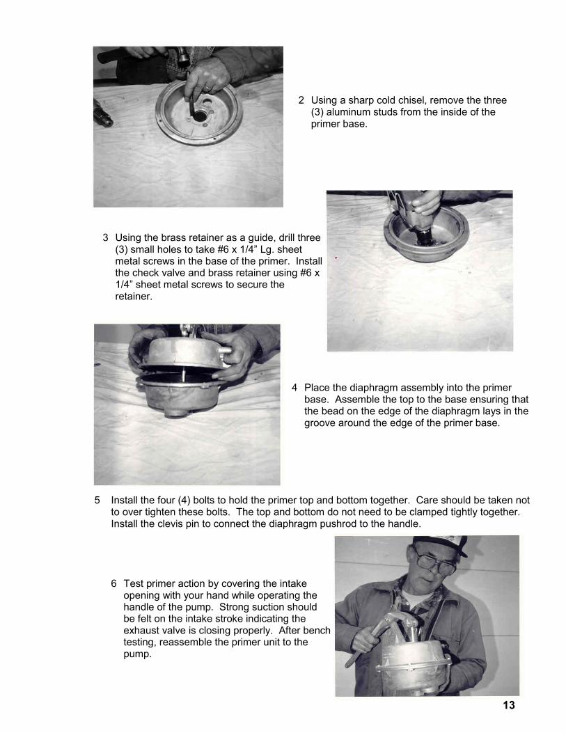
5 Install the four (4) bolts to hold the primer top and bottom together. Care should be taken not to over tighten these bolts. The top and bottom do not need to be clamped tightly together. Install the clevis pin to connect the diaphragm pushrod to the handle.
2 Using a sharp cold chisel, remove the three (3) aluminum studs from the inside of the primer base.
3 Using the brass retainer as a guide, drill three (3) small holes to take #6 x 1/4” Lg. sheet metal screws in the base of the primer. Install the check valve and brass retainer using #6 x 1/4” sheet metal screws to secure the retainer.
4 Place the diaphragm assembly into the primer base. Assemble the top to the base ensuring that the bead on the edge of the diaphragm lays in the groove around the edge of the primer base.
6 Test primer action by covering the intake opening with your hand while operating the handle of the pump. Strong suction should be felt on the intake stroke indicating the exhaust valve is closing properly. After bench testing, reassemble the primer unit to the pump.

Notes

15
PARTS SECTION
Trailer Assembly .................................................................................................................. 15-16
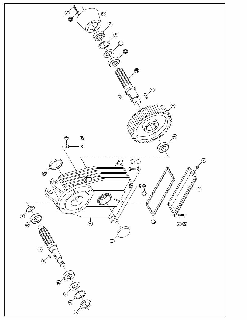
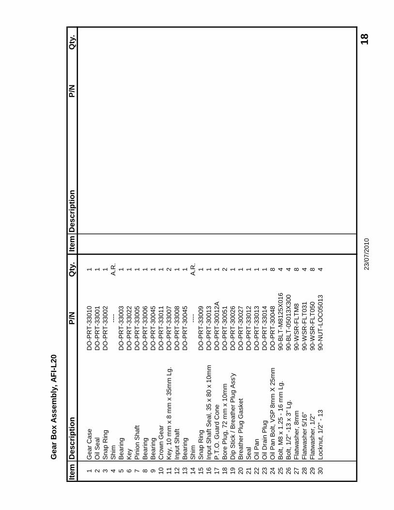
Gearbox
AFI – L20 ............................................................................................................. 17-18
AFI – L24 – L35 ................................................................................................... 19-20
AFI – L27 – L35 Pedestal Mount ......................................................................... 21-22
AFI – L27 – L35 SAE 3 ........................................................................................ 23-24
Pump Case
AFI – L20 ............................................................................................................. 25-26
AFI – L24 – L35 ................................................................................................... 27-28
AFI – L27 – L35 SAE 3 ........................................................................................ 29-30
Primer Assembly .................................................................................................................. 31-32
Hand Primer ............................................................................................................... 33-34
Discharge Assembly ............................................................................................................ 35-36
Suction Hose Assembly .............................................................................................. 37-38


Tra
ile
r A
ss
em
bly
Ite
mD
es
cri
pti
on
P/N
Qty
.It
em
Des
cri
pti
on
P/N
Qty
.
AF
I-L
27 -
AF
I-L
35
AF
I-L
20 -
AF
I-L
24
1D
oda P
um
p a
nd G
ear
Box
----
1
2P
um
p T
raile
rD
O-P
RT
-30200C
12
Pum
p T
raile
r (N
ot as s
how
n)
DO
-PR
T-3
0100
1
3W
heel A
ss'y
Co
nsis
tin
g o
f;55-0
71
23
Wheel A
ssem
bly
55-0
56
2
4T
ire
----
1T
ire
----
1
5R
im--
--1
Rim
----
1
6V
alv
e S
tem
----
1V
alv
e S
tem
----
1
7H
ub
Ass'y
; C
on
sis
tin
g O
f55-0
18
27
Hub A
ssem
bly
(4
bolt)
55-0
02
2
8G
rease S
eal
55-0
15
1
9In
ner
Bearing -
Cone
55-0
20
1
-In
ner
Bearing -
Cup (
Not S
how
n)
55-0
19
1
10
Wheel H
ub, 5 B
olt
55-0
18A
1
-O
ute
r B
earing -
Cup (
Not S
how
n)
55-0
21
1
11
Oute
r B
earing -
Cone
55-0
22
1
12
Dust C
ap
55-0
23
1
13
Wheel B
olt, 1/2
" -
20 U
NF
55-0
07
5
14
Washer
55-0
24
2
15
Cotter
Pin
55-0
09
2
16
Spin
dle
Nut
55-0
08
2
17
Bolt, 1/2
" -1
3 x
3"
Lg.
90-B
LT
-05013X
300
4
18
SA
E F
latw
asher,
1/2
"90-W
SR
-SA
E050
4
19
Locknut, 1
/2"
- 13
90-N
UT
-LO
C05013
4
20
Decal, "
Do N
ot E
ngage P
TO
…"
40-2
59
1
No
t S
ho
wn
Bondio
li #6 5
40 R
PM
PT
O S
haft
BP
-PT
O-6
13861386
1
or
Bondio
li #6 1
000 R
PM
PT
O S
haft
BP
-PT
O-6
138211386
1 23/0
7/2
010
1
6
Ge
ar
Bo
x A
ss
em
bly
, A
FI-
L20
Ite
mD
es
cri
pti
on
P/N
Qty
.It
em
Des
cri
pti
on
P/N
Qty
.
1G
ear
Case
DO
-PR
T-3
3010
1
2O
il S
eal
DO
-PR
T-3
3001
1
3S
nap R
ing
DO
-PR
T-3
3002
1
4S
him
----
A.R
.
5B
earing
DO
-PR
T-3
3003
1
6K
ey
DO
-PR
T-3
3022
1
7P
inio
n S
haft
DO
-PR
T-3
3005
1
8B
earing
DO
-PR
T-3
3006
1
9B
earing
DO
-PR
T-3
0045
1
10
Cro
wn G
ear
DO
-PR
T-3
3011
1
11
Key,
10 m
m x
8 m
m x
35m
m L
g.
DO
-PR
T-3
3007
2
12
Input S
haft
DO
-PR
T-3
3008
1
13
Bearing
DO
-PR
T-3
0045
1
14
Shim
----
A.R
.
15
Snap R
ing
DO
-PR
T-3
3009
1
16
Input S
haft
Seal, 3
5 x
80 x
10m
mD
O-P
RT
-30013
1
17
P.T
.O. G
uard
Cone
DO
-PR
T-3
0012A
1
18
Bore
Plu
g, 72 m
m x
10m
mD
O-P
RT
-30051
2
19
Dip
Stick / B
reath
er
Plu
g A
ss'y
DO
-PR
T-3
0026
1
20
Bre
ath
er
Plu
g G
asket
DO
-PR
T-3
0027
1
21
Seal
DO
-PR
T-3
3012
1
22
Oil
Pan
DO
-PR
T-3
3013
1
23
Oil
Dra
in P
lug
DO
-PR
T-3
3014
1
24
Oil
Pan B
olt, V
SP
8m
m X
25m
mD
O-P
RT
-30048
8
25
Bolt, M
8 x
1.2
5 -
16 m
m L
g.
90-B
LT
-M8125X
016
4
26
Bolt, 1/2
" -1
3 x
3"
Lg.
90-B
LT
-05013X
300
4
27
Fla
twasher,
8m
m90-W
SR
-FLT
M8
8
28
Fla
twasher
5/1
6"
90-W
SR
-FLT
031
4
29
Fla
twasher,
1/2
"90-W
SR
-FLT
050
8
30
Locknut, 1
/2"
- 13
90-N
UT
-LO
C05013
4 23/0
7/2
010
1
8


Ge
ar
Bo
x A
ss
em
bly
, A
FI-
L24
~>
AF
I-L
35
Ite
mD
es
cri
pti
on
P/N
Qty
.It
em
Des
cri
pti
on
P/N
Qty
.
1G
earC
ase
DO
-PR
T-3
0001
126
Bolt, M
8 x
1.2
5 -
16 m
m L
g.
90-B
LT
-M8125X
016
4
2C
row
n G
ear
27
Bolt, M
12 x
1.7
5-6
0m
m L
g.
90-B
LT
-M12175X
060
4
540 R
PM
(4.9
3 : 1
) 6
9 T
ooth
DO
-PR
T-3
0022A
128
Bolt, 1/2
" -1
3 x
3"
Lg.
90-B
LT
-05013X
300
4
1000 R
PM
(3.3
5 : 1
) 64 T
ooth
DO
-PR
T-3
0022B
129
Fla
twasher,
8 m
m90-W
SR
-FLT
M8
8
3P
inio
n S
haft
30
Fla
twasher,
5/1
6"
90-W
SR
-FLT
031
4
540 R
PM
(4.9
3 : 1
) 1
4 T
ooth
DO
-PR
T-3
0023A
131
Fla
twasher,
1/2
"90-W
SR
-FLT
050
8
1000 R
PM
(3.3
5 : 1
) 19 T
ooth
DO
-PR
T-3
0023B
132
Lockw
asher,
1/2
"90-W
SR
-LO
C050
4
4B
earing P
late
DO
-PR
T-3
0002
133
Locknut, 1
/2"
- 13
90-N
UT
-LO
C05013
4
5P
inio
n S
haft
Seal
DO
-PR
T-3
0014
1
6B
earing P
late
Gasket
DO
-PR
T-3
0030
1
7T
aper
Rolle
r B
earing
DO
-PR
T-3
0020
1
8S
him
----
A.R
.
9C
row
n G
ear
Key,
10 x
8 x
45m
mD
O-P
RT
-30028
3
10
Ball
Bearing
DO
-PR
T-3
0019
1
11
Shim
----
A.R
.
12
Bearing
DO
-PR
T-3
0018
1
13
Input S
haft
DO
-PR
T-3
0017
1
14
Bearing
DO
-PR
T-3
0045
1
15
Bearing A
dju
stm
ent S
him
DO
-PR
T-3
0029
A.R
.
16
Snap R
ing
DO
-PR
T-3
0021
1
17
Input S
haft
Seal, 3
5 x
80 x
10m
mD
O-P
RT
-30013
1
18
P.T
.O. G
uard
Cone
DO
-PR
T-3
0012A
1
19
Bore
Plu
g, 72 m
m x
10m
mD
O-P
RT
-30051
2
20
Dip
Stick / B
reath
er
Plu
g A
ss'y
DO
-PR
T-3
0026
1
21
Bre
ath
er
Plu
g G
asket
DO
-PR
T-3
0027
1
22
Oil
Pan
DO
-PR
T-3
0043
1
23
Oil
Dra
in P
lug, 1/8
" -
28 T
PI
(British T
hre
ad, F
ine)
DO
-PR
T-3
0044
1
24
Gearb
ox O
il P
an G
asket
DO
-PR
T-3
0047
1
25
Oil
Pan B
olt, V
SP
8m
m X
25m
mD
O-P
RT
-30048
8 23/0
7/2
010
2
0


Ge
ar
Bo
x A
ss
em
bly
, P
ed
ista
l M
ou
nt
Ite
mD
es
cri
pti
on
P/N
Qty
.It
em
Des
cri
pti
on
P/N
Qty
.
1S
nap R
ing
DO
-PR
T-3
4-0
01
1
2O
il S
eal, 4
5 x
60 x
10
DO
-PR
T-3
4-0
02
2
3O
-rin
gD
O-P
RT
-34-0
03
1
4C
over
(Bearing R
eta
iner)
DO
-PR
T-3
4-0
04
1
5B
earing
DO
-PR
T-3
4-0
05
1
6O
il B
reath
er
Plu
gD
O-P
RT
-34-0
06
1
7B
earing S
upport
(P
edis
tal)
DO
-PR
T-3
4-0
07
1
8K
ey,
8m
m x
7m
m x
45m
mD
O-P
RT
-30-0
39
1
9S
haft
DO
-PR
T-3
4-0
08
1
10
Key,
12m
m x
8m
m x
70m
mD
O-P
RT
-34-0
09
1
11
Bearing
40-1
42
1
12
Cover
DO
-PR
T-3
4-0
10
1
13
Safe
ty F
lange
---
14
Fla
nge
---
15
Ball
---
16
Gre
ase F
itting, M
10
---
17
Safe
ty B
olt
---
18
Bolt, M
10 x
1.5
0-2
0m
m L
g.
90-B
LT
-M10150X
020
19
Bolt, M
10 x
1.5
0-2
5m
m L
g.
90-B
LT
-M10150X
025
20
Bolt, M
12 x
1.7
5-3
0m
m L
g.
90-B
LT
-M12175X
030
21
Alu
min
um
Fla
twasher,
10m
mD
O-P
RT
-30-0
49
22
Washer
---
23
Fla
twasher,
10m
m90-W
SR
-FLT
M10
24
Fla
twasher,
12m
m90-W
SR
-FLT
M12
25
Locknut, 1
0m
m--
-
23/0
7/2
010
2
2


SA
E 3
Pu
mp
Mo
un
t
Ite
mD
es
cri
pti
on
P/N
Qty
.It
em
Des
cri
pti
on
P/N
Qty
.
1S
AE
3 P
um
p M
ount H
ousin
gD
O-P
RT
-SA
E3
1
DO
-PR
T-3
5018A
1
88-B
LT
-03824X
100
4
88-W
SR
-LO
C038
4
2A
ir V
ent
DO
-PR
T-3
5014
1
3O
il D
ip S
tick
CA
-PR
T-3
1819
1
4G
alv
. D
rain
Plu
g40-N
PT
-PLG
075G
1
5S
haft
Seal, 4
5x85x10
DO
-PR
T-3
5006
1
685m
m Inte
rnal S
nap R
ing
40-1
41
1
7B
earing, 45m
m 6
209
40-1
42
1
8P
um
p S
haft
DO
-PR
T-3
5002-E
1
9W
ear
Sle
eve
DO
-PR
T-3
5003
1
10
Bearing 5
309
DO
-PR
T-3
5008
1
Bearing 5
309 (
Alt.)
DO
-PR
T-3
5017
1
11
100m
m Inte
rnal R
eta
inin
g R
ing
DO
-PR
T-3
5009
1
12
Shaft
Seal 45x100x10
DO
-PR
T-3
5010
1
13
Seal R
eta
inin
g R
ing
DO
-PR
T-3
5011
2
14
Pum
p S
eal
DO
-PR
T-3
5007
3
15
Seal G
land
DO
-PR
T-3
5004
1
16
Spacer
Rin
gD
O-P
RT
-35001
1
17
Slin
ger
BE
-PR
T-S
10964
1
18
SH
CS
, M
10-1
.50 x
30 m
m L
g.
90-S
CR
-SH
M10150X
030
4
Bearing P
late
D
O-P
RT
-35-0
07
1
DO
-PR
T-3
5-0
18-A
1
Cadm
an S
erial N
um
ber
Tag
40-2
38
1 10/1
2/2
017
2
4


Pu
mp
Ca
se
As
se
mb
ly,
AF
I-L
20
Ite
mD
es
cri
pti
on
P/N
Qty
.It
em
Des
cri
pti
on
P/N
Qty
.
1S
uction H
ousin
gD
O-P
RT
-33015
125
Locknut, M
10 x
1.5
090-N
UT
-LO
CM
10150
16
2O
-Rin
gD
O-P
RT
-31002
126
Locknut, M
14 x
2.0
090-N
UT
-LO
CM
14200
4
3Im
pelle
r K
nife
DO
-PR
T-3
0038
2
4Im
pelle
r C
over
DO
-PR
T-3
3016
1P
TO
Guard
Cone
DO
-PR
T-3
0-0
12A
1
5Im
pelle
r N
ut
DO
-PR
T-3
3017
1
6Im
pelle
r N
ut Lockw
asher
DO
-PR
T-3
0024
1
7Im
pelle
r K
ey, 8m
m x
7m
m x
45m
mD
O-P
RT
-30039
2
8Im
pelle
rD
O-P
RT
-33018
1
9V
olu
teD
O-P
RT
-33019
1
10
Dis
charg
e G
asket
DO
-PR
T-3
0040
1
11
Gla
nd P
late
O-R
ing
1
12
Gla
nd P
late
DO
-PR
T-3
0007
1
13
Volu
te S
pacer
DO
-PR
T-3
3020
1
14
Bearing S
hie
ldD
O-P
RT
-30042A
1
15
Sta
inle
ss S
teel S
haft
Bushin
gD
O-P
RT
-33021
1
Tu
ng
ste
n S
eal K
it C
on
sis
tin
g o
f;D
O-P
RT
-30016T
1
AS
pring
----
1
BS
eal D
rive A
ssem
bly
O-R
ing
----
1
CS
eal D
rive A
ssem
bly
----
1
DS
tationary
Seal O
-Rin
g--
--1
ES
tationary
Seal R
ing
----
1
16
Bolt, M
10 x
1.5
0 -
30m
m L
g.
90-B
LT
-M10150X
030
4
17
Bolt, M
10 x
1.5
0 -
40m
m L
g.
90-B
LT
-M10150X
040
2
18
Bolt, M
12 x
1.7
5 -
30m
m L
g.
90-B
LT
-M12175X
030
4
19
Bolt, M
12 x
1.7
5 -
60m
m L
g.
90-B
LT
-M12175X
060
8
20
C.S
. B
olt, M
14 x
2.0
0 -
30m
m L
g.
DO
-PR
T-3
0-0
50
4
21
Bolt, 5/1
6"
- 18 x
1/2
" Lg.
90-B
LT
-03118X
050
2
22
Alu
min
um
Seal W
asher,
10m
mD
O-P
RT
-30049
4
23
Fla
twasher,
10m
m90-W
SR
-FLT
M10
4
24
Lockw
asher,
14m
m90-W
SR
-LO
CM
14
4 23/0
7/2
010
2
6

Pu
mp
Ca
se
As
se
mb
ly,
AF
I-L
24
~>
AF
I-L
35
Ite
mD
es
cri
pti
on
P/N
Qty
.It
em
Des
cri
pti
on
P/N
Qty
.
1B
all
Cla
mp R
ing, 150m
mD
O-P
RT
-30011
1T
un
gste
n S
eal K
it C
on
sis
tin
g o
f;D
O-P
RT
-30016T
1
2D
oda B
all
and S
hank -
4"
DO
-PR
T-3
00104
1A
Spring
----
1
-D
oda B
all
and S
hank -
5"
DO
-PR
T-3
00105
1B
Seal D
rive A
ssem
bly
O-R
ing
----
1
-D
oda B
all
and S
hank -
6"
DO
-PR
T-3
00106
1C
Seal D
rive A
ssem
bly
----
1
3S
uction O
-rin
g, 150 m
mD
O-P
RT
-30035
1D
Sta
tionary
Seal O
-Rin
g--
--1
4C
heck V
alv
e H
ousin
gD
O-P
RT
-30006
1E
Sta
tionary
Seal R
ing
----
1
-R
ubberized P
late
(
Not S
how
n)
DO
-PR
T-3
0037
1
-V
alv
e H
old
er
(N
ot S
how
n)
DO
-PR
T-3
0037A
124
Bolt, M
10 x
1.5
0 -
30m
m L
g.
90-B
LT
-M10150X
030
4
-V
alv
e S
upport
(
Not S
how
n)
DO
-PR
T-3
0037B
125
Bolt, M
10 x
1.5
0 -
35m
m L
g.
90-B
LT
-M10150X
035
2
5C
heck V
alv
e H
ousin
g G
asket
DO
-PR
T-3
0036
126
Bolt, M
10 x
1.5
0 -
40m
m L
g.
90-B
LT
-M10150X
040
12
6O
-Rin
gD
O-P
RT
-31002
127
Bolt, M
12 x
1.7
5 -
30m
m L
g.
90-B
LT
-M12175X
030
8
7Im
pelle
r K
nife
DO
-PR
T-3
0038
228
Bolt, M
12 x
1.7
5 -
60m
m L
g.
90-B
LT
-M12175X
060
4
8Im
pelle
r C
over
29
C.S
. B
olt, M
14 x
2.0
0 -
30m
m L
g.
DO
-PR
T-3
0-0
50
4
AF
I-L24 P
um
pD
O-P
RT
-32002
130
Bolt, 5/1
6"
- 18 x
1/2
" Lg.
90-B
LT
-03118X
050
2
AF
I-L27 P
um
pD
O-P
RT
-30008-A
131
Alu
min
um
Seal W
asher,
10m
mD
O-P
RT
-30049
4
AF
I-L35 P
um
pD
O-P
RT
-31003-A
132
Fla
twasher,
10m
m90-W
SR
-FLT
M10
4
9Im
pelle
r Lock N
ut
DO
-PR
T-3
0025L
133
Lockw
asher,
14m
m90-W
SR
-LO
CM
14
4
Impelle
r N
ut (
Used w
ith 3
0024)
DO
-PR
T-3
0025
134
Locknut, M
10 x
1.5
090-N
UT
-LO
CM
10150
16
Impelle
r Lock W
asher
DO
-PR
T-3
0024
135
Locknut, M
14 x
2.0
090-N
UT
-LO
CM
14200
4
11
Impelle
r K
ey, 8m
m x
7m
m x
45m
mD
O-P
RT
-30039
2
12
Impelle
r
AF
I-L24 P
um
pD
O-P
RT
-32001
1
AF
I-L27 P
um
pD
O-P
RT
-30009
1
AF
I-L35 P
um
pD
O-P
RT
-31004
1
13
Volu
te S
uction E
xte
nsio
nD
O-P
RT
-30005
1
(AF
I-L35 P
um
p o
nly
)D
O-P
RT
-31001
1
14
Volu
te (
AF
I-L 2
7)
DO
-PR
T-3
0004
1
(AF
I-L35 P
um
p o
nly
)D
O-P
RT
-31005
1
15
Dis
charg
e G
asket
DO
-PR
T-3
0040
1
16
Secondary
Seal O
-rin
gD
O-P
RT
-35015
1
17
Gla
nd P
late
DO
-PR
T-3
0007
1
18
Volu
te S
pacer
DO
-PR
T-3
0003
1
19
Bearing S
hie
ldD
O-P
RT
-30042A
1 23/0
7/2
010
2
8

Pu
mp
Ca
se
As
se
mb
ly,
SA
E 3
Ite
mD
es
cri
pti
on
P/N
Qty
.It
em
Des
cri
pti
on
P/N
Qty
.
1B
all
Cla
mp R
ing, 150m
mD
O-P
RT
-30011
115
Bolt, M
10 x
1.5
0 -
35m
m L
g.
90-B
LT
-M10150X
035
4
2D
oda B
all
and S
hank -
4"
DO
-PR
T-3
00104
116
Bolt, M
10 x
1.5
0 -
40m
m L
g.
90-B
LT
-M10150X
040
12
-D
oda B
all
and S
hank -
5"
DO
-PR
T-3
00105
117
Bolt, M
14 x
2.0
0 -
30m
m L
g.
90-B
LT
-M14200X
030
12
-D
oda B
all
and S
hank -
6"
DO
-PR
T-3
00106
118
C.S
. B
olt, M
14 x
2.0
0 -
30m
m L
g.
DO
-PR
T-3
0-0
50
4
3S
uction O
-rin
g, 150 m
mD
O-P
RT
-30035
119
Bolt, 5/1
6"
- 18 x
1/2
" Lg.
90-B
LT
-03118X
050
2
4C
heck V
alv
e H
ousin
gD
O-P
RT
-30006
120
Alu
min
um
Seal W
asher,
10m
mD
O-P
RT
-30049
4
-R
ubberized P
late
(
Not S
how
n)
DO
-PR
T-3
0037
121
Fla
twasher,
10m
m90-W
SR
-FLT
M10
4
-V
alv
e H
old
er
(N
ot S
how
n)
DO
-PR
T-3
0037A
122
Locknut, M
10 x
1.5
090-N
UT
-LO
CM
10150
16
-V
alv
e S
upport
(
Not S
how
n)
DO
-PR
T-3
0037B
1
5C
heck V
alv
e H
ousin
g G
asket
DO
-PR
T-3
0036
1
6V
olu
te S
uction E
xte
nsio
n
(AF
I-L35)
DO
-PR
T-3
1001
1
(AF
I-L27)
DO
-PR
T-3
0005
1
7Im
pelle
r K
nife
DO
-PR
T-3
0038
2
8Im
pelle
r C
over (A
FI-
L35)
DO
-PR
T-3
1003
1
(AF
I-L27)
DO
-PR
T-3
0008
1
9O
-Rin
gD
O-P
RT
-31002
1
10
Impelle
r Lock N
ut
DO
-PR
T-3
0025L
1
11
Impelle
r K
ey, 8m
m x
7m
m x
45m
mD
O-P
RT
-30039
2
12
Impelle
r
(AF
I-L35)
DO
-PR
T-3
1004
1
(AF
I-L27)
DO
-PR
T-3
0009
1
13
Volu
te
(AF
I-L35)
DO
-PR
T-3
1005
1
(AF
I-L27)
DO
-PR
T-3
0004
1
14
Dis
charg
e G
asket
DO
-PR
T-3
0040
1 23/0
7/2
010
3
0

Pri
me
r A
ss
em
bly
Ite
mD
es
cri
pti
on
P/N
Qty
.It
em
Des
cri
pti
on
P/N
Qty
.
1H
and P
rim
er
IR-P
MR
-CA
R46-0
00
1
2G
al. R
educin
g B
ushin
g, 3/4
" x 3
/8"
40-N
PT
-RB
075X
038G
1
3G
alv
. N
ipple
(cut in
half)
3/8
" N
PT
x 4
" Lg.
40
-NP
T-N
PL0
38
X4
00
G1
4G
ear
Cla
mp, #8
50-0
24
2
5S
uction H
ose, 5/8
"IR
-HO
Z-S
UC
063
4 in.
6G
alv
aniz
ed P
lug, 3/4
"40-N
PT
-PLG
075G
1
7B
arb
Fitting
3/4
" N
PT
. x 3
/4"
Hose B
arb
40-N
PT
-BR
B075G
2
8G
ear
Cla
mp, #12
50-0
27
2
9S
uction H
ose, 3/4
"IR
-HO
Z-S
UC
075
48 in.
10
Bra
ss B
all
Valv
e, 3/4
"40-N
PT
-VLV
075B
LLF
F1
11
Galv
aniz
ed C
lose N
ipple
, 3/4
"40-N
PT
-NP
LC
075G
1
12
Galz
aniz
ed S
treet E
lbow
, 3/4
"40-N
PT
-ELS
075X
90G
1
13
M8 x
1.2
5 -
25 m
m L
g. B
olt
90-B
LT
-M8125X
025
3
14
Lockw
asher,
8 m
m90-W
SR
-LO
CM
08
3 23/0
7/2
010
3
2


Han
d P
rim
er
As
se
mb
ly
Ite
mD
es
cri
pti
on
P/N
Qty
.It
em
Des
cri
pti
on
P/N
Qty
.
1H
andle
IR-P
MR
-CA
R46501
1
2T
op C
over
IR-P
MR
-CA
R46502
1
3D
iaphra
m C
onnecting R
od
IR-P
MR
-CA
R46503
1
4D
iaphra
m P
late
IR-P
MR
-CA
R46504
2
5D
iaphra
mIR
-PM
R-C
AR
46505
1
6In
take R
ubber
IR-P
MR
-CA
R46506
1
7R
eta
inin
g W
asher
IR-P
MR
-CA
R46509
1
8B
ase
IR-P
MR
-CA
R46507
1
9E
xhaust V
alv
eIR
-PM
R-C
AR
46508
1
10
Cotter
Pin
, 3/3
2"
x 3
/4"
Lg.
IR-P
MR
-CA
R46501A
2
11
Cle
vis
Pin
, 3/8
" x 1
7/1
6"
Lg.
IR-P
MR
-CA
R46501B
2
12
Reta
inin
g S
cre
w, #6 x
1/4
" Lg.
90-S
CR
-RM
0632X
025
3
13
Bolt, M
6 x
1.0
0 -
30m
m L
g.
90-B
LT
-M6100X
030
4
14
Fla
twasher,
3/8
"90-W
SR
-FLT
038
2
15
Lockw
asher,
10m
m90-W
SR
-LO
CM
10
2
16
Hex N
ut, M
6 x
1.0
090-N
UT
-HE
XM
6100
4
17
Hex N
ut, M
10 x
1.5
090-N
UT
-HE
XM
10150
2 23/0
7/2
010
3
4


Dis
ch
arg
e A
ss
em
bly
Ite
mD
es
cri
pti
on
P/N
Qty
.It
em
Des
cri
pti
on
P/N
Qty
.
1D
ischarg
e A
dapte
r1
3"
NP
T x
4"
Rain
Way
Rin
glo
ck
IR-T
C3-4
RW
AY
/RL
---
IR
-TC
3-5
RW
AY
/RL
---
No
te:
Man
y o
ther
ad
ap
ters
av
ailab
le
23"
Gate
Valv
e4
0-N
PT
-VL
V3
00
GA
TF
F1
4"
Gate
Valv
e (
Std
. on A
FI -L
35)
40
-NP
T-V
LV
40
0G
AT
FF
Opt.
3"
Ball
Valv
e (
Not S
how
n)
40
-NP
T-V
LV
30
0B
LL
FF
Opt.
4"
Ball
Valv
e (
Not S
how
n)
40
-NP
T-V
LV
40
0B
LL
FF
Opt.
3D
ischarg
e F
lange W
eld
ment
1
(
AF
I-L24, A
FI-
L27)
DO
-PR
T-3
0041A
---
(AF
I-L20 o
nly
)
DO
-PR
T-3
3025
---
(AF
I-L35 o
nly
)
DO
-PR
T-3
5013
---
4D
ischarg
e G
asket
DO
-PR
T-3
0040
1
Ga
ug
e P
rote
cto
r K
it C
on
sis
tin
g o
f;IR
-GA
U-P
RO
TE
CT
-KIT
1
5G
auge P
rote
cto
r B
ody, 3/4
NP
T15-0
82-0
75
1
6G
auge P
rote
cto
r D
iaphra
m15-0
83
1
7G
auge P
rote
cto
r B
ody, 1/4
NP
T15-0
82-0
25
1
8B
olt, 5/1
6"
x 2
1/2
" Lg.
90-B
LT
-03118X
250
5
9S
AE
Fla
twasher,
5/1
6"
90-W
SR
-FLT
031
10
10
Locknut, 5
/16"
- 18
90-N
UT
-LO
C031
5
11
0-2
00 P
SI Liq
uid
Fill
ed G
auge
45-0
18
1
12
M10 x
1.5
0 -
50 m
m L
g. B
olt
90-B
LT
-M10150X
050
6
13
Locknut, M
10 x
1.5
090-N
UT
-LO
CM
10
6 23/0
7/2
010
3
6


Su
cti
on
Ho
se
As
se
mb
ly
Ite
mD
es
cri
pti
on
P/N
Qty
.It
em
Des
cri
pti
on
P/N
Qty
.
1A
Suction S
cre
en, 4"
(
w / c
lam
p)
IR-S
UC
-45004C
1
Suction S
cre
en, 5"
(
w / c
lam
p)
IR-S
UC
-45049C
1
Suction S
cre
en, 6"
(
w / c
lam
p)
IR-S
UC
-45005C
1
1B
Suction S
cre
en, 4"
IR-S
UC
-45004T
1
Suction S
cre
en, 5"
IR-S
UC
-45049T
1
Suction S
cre
en, 6"
IR-S
UC
-45005T
1
24"
Alu
min
um
Tube, R
olle
d (
1)
end
IR-T
UB
-4H
EA
VY
1 F
t.
6"
Alu
min
um
Tube, R
olle
d (
1)
end
IR-T
UB
-6H
EA
VY
1 F
t.
34"
ID. S
uction H
ose
IR-H
OZ
-SU
C400T
F25 F
t.
5"
ID. S
uction H
ose
IR-H
OZ
-SU
C500T
F25 F
t.
6"
ID. S
uction H
ose
IR-H
OZ
-SU
C600T
F25 F
t.
4S
DB
C 4
00 C
lam
p (
4")
50-0
23
2
SD
BC
600 C
lam
p (
6")
50-0
21
2 23/0
7/2
010
3
8
