cad cam lab manual - anurag college of engineering · 2019-05-22 · cad cam lab manual b.tech - iv...
TRANSCRIPT

CAD CAM LAB MANUAL
B.TECH - IV YEAR - I
Department of Mechanical Engineering,
Anurag College of Engineering,
Aushapur(V),Ghatkesar(M). Medchal (Dist),TS-501301

INTRODUCTION:
Computer –Aided Design (CAD), also known as computer –aided drafting is the use of computer
systems to assist in the creation, modification, analysis or optimization of a design. Computer-
aided drafting describes the process creating a technical drawing with the use of computer
software.CAD software is used to increase the productivity of the designer, improve the quality
of design, improve communications through documentation, and to create data base for
manufacturing. CAD output is often in the form of electronic files for print or machining
operations. CAD software uses either vector based graphics to depict the objects of traditional
drafting, or may also produce raster graphics showing the overall appearance of designed
objects.
CAD often involves more than just shapes. As in the manual drafting of technical and
engineering drawings, the output of CAD must convey information, such as materials, processes,
dimensions and tolerance, according to the application-specific conventions.
CAD may be used to design curves and figures in two-dimensional space, or curves, surface and
solids in three dimensional spaces.
CAD is an important industrial art extensively used in many applications, including automotive,
ship building and aerospace industries, industrial and architectural design, prosthetics and many
more.CAD is also widely used to produce computer animation for special effects in movies,
advertising and technical manuals. The modern ubiquity and the power of computers means that
even perfume bottles and shampoo designed using techniques unheard of by engineers in
1960’s.Because of which enormous economic importance, CAD has been a major driving force
for research in computational geometry, computer graphics and discrete differential geometry.
While the goal of the automated CAD system is to increase efficiency, they are not necessarily
the best way to allow new comers to understand the geometrical principles of solid modeling.
For this, scripting languages such as PLASM (programming language of solid modeling) are
more suitable.
CAD is one part of the whole Digital Product Development (DPD) activity within the Product
Lifecycle Management (PLM) process, and as such is used together with other tools, which are
either integrated modules or stand-above products, such as :
-Computer-Aided Engineering (CAE)
-Finite Element Analysis (FEA)
-Computer –Aided Manufacturing (CAM) including instructions to Computer Numerical Control
(CNC) machines
-Photo realistic rendering

-document management and revision control using Product Data Management (PDM)
THE BASIC AUTO-CAD COMMANDS ARE:
A-Arc M-Move
B-Block diagram O-Offset
C- Circle R-Redraw
D-Dimensioning S-Sketch
E- Erase T-Text
F- Fillet U-previous command
G-Grouping V-View
H-Hatching W-Write block
I-insert X-explode
J-Join Z-Zoom
L-Line

EXPERIMENT-1
AIM - To develop the part drawing of connecting rod in the orthographic representation.
List of commands:
Line-To draw a line of required dimension.
Circle- To draw a circle of required radius.
Poly line- To draw multiple lines of required dimensions.
Arc- To draw arc of required dimensions.
Trim- To remove unwanted or excess
dimensions of the element.
Zoom- To enlarge or reduce the view of
component.
Fillet- To join sharp corners with a curve.
Mirror- To reflect the image on other side of
the object.
Offset- To draw the image of the object at
required distance.
Erase- To erase any object.
Block- To convert into single entity.
Hatch- Used to hatch enclosed area.
Join-To join two objects.
Break- To cut the object to required dimensions.
RESULT: Thus, the part drawing of connecting rod is drawn in orthographic view.

EXPERIMENT-2
AIM - To develop the part drawing of Screw jack in the orthographic representation using Auto
cad.
List of commands:
Line-To draw a line of required dimension.
Circle- To draw a circle of required radius.
Polyline- To draw multiple lines of
required dimensions.
Arc- To draw arc of required dimensions.
Trim- To remove unwanted or excess
dimensions of the element.
Zoom- To enlarge or reduce the view of
component.
Fillet- To join sharp corners with a curve.
Mirror- To reflect the image on other side
of the object.
Offset- To draw the image of the object at
required distance.
Erase- To erase any object.
Block- To convert into single entity.
Hatch- Used to hatch enclosed area.
Join-To join two objects.
Break- To cut the object to required
dimensions.
RESULT: Thus, the part drawing of screw jack is drawn in orthographic view
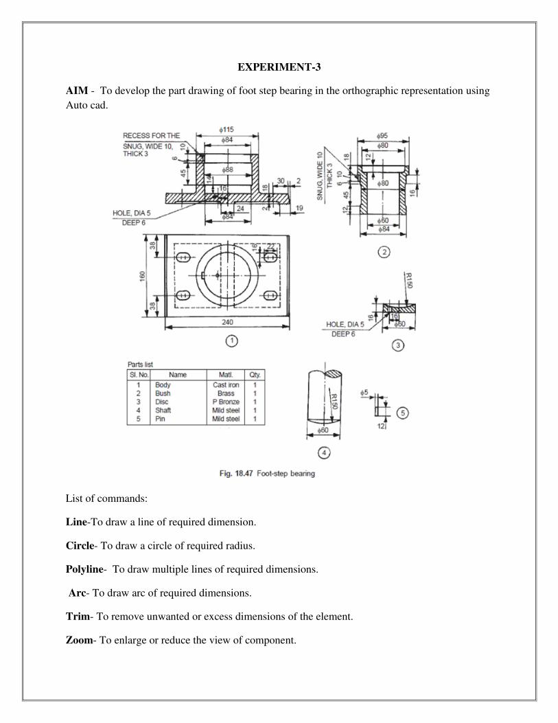
EXPERIMENT-3
AIM - To develop the part drawing of foot step bearing in the orthographic representation using
Auto cad.
List of commands:
Line-To draw a line of required dimension.
Circle- To draw a circle of required radius.
Polyline- To draw multiple lines of required dimensions.
Arc- To draw arc of required dimensions.
Trim- To remove unwanted or excess dimensions of the element.
Zoom- To enlarge or reduce the view of component.

Fillet- To join sharp corners with a curve.
Mirror- To reflect the image on other side of the object.
Offset- To draw the image of the object at required distance.
Erase- To erase any object.
Block- To convert into single entity.
Hatch- Used to hatch enclosed area.
Join-To join two objects.
Break- To cut the object to required dimensions.
RESULT: Thus, the part drawing of foot step bearing is drawn in orthographic view.

EXPERIMENT-4
AIM - To develop the part drawing of fuel injector in the orthographic representation.
List of commands:
Line-To draw a line of required dimension.
Circle- To draw a circle of required radius.
Arc- To draw arc of required dimensions.
Zoom- To enlarge or reduce the view of
component.
Fillet- To join sharp corners with a curve.
Block- To convert into single entity.
Hatch- Used to hatch enclosed area.
Mirror- to reflect the image on the other side
of the object.
RESULT: Thus, the part drawing of fuel injector is drawn in orthographic view.

EXPERIMENT-5
AIM - To develop the part drawing of revolving center in the orthographic representation.
List of commands:
Line-To draw a line of required dimension.
Circle- To draw a circle of required radius.
Arc- To draw arc of required dimensions.
Zoom- To enlarge or reduce the view of
component.
Fillet- To join sharp corners with a curve.
Mirror- To reflect the image on other side of
the object.
Poly line- To draw multiple lines of any
dimensions.
Block- To convert into single entity.
Hatch- Used to hatch enclosed area.
RESULT: Thus, the part drawing of revolving centre is drawn in orthographic view.

EXPERIMENT-6
AIM - To develop the part drawing of four jaw chuck in the orthographic representation.
List of commands:
Line-To draw a line of required dimension.
Circle- To draw a circle of required radius.
Polyline- To draw multiple lines of
required dimensions.
Arc- To draw arc of required dimensions.
Zoom- To enlarge or reduce the view of
component.
Fillet- To join sharp corners with a curve.
Mirror- To reflect the image on other side
of the object.
Block- To convert into single entity.
Hatch- Used to hatch enclosed area.
RESULT: Thus, the part drawing of four jaw chuck is drawn in orthographic view.

INTRODUCTION TO PRO-E
This introduction discusses the basic tasks in using Pro-E such as design modeling , calibration, managing data
working with module design , unferencing and so on.
Pro-E software is specially used for modeling and also used for composites , sheet metal , pro-chart etc.
Understanding the
Pro/ENGINEER Interface
The Main Interface includes the
following areas:
• Graphics Area
• Main Menu
• Toolbars
• Dashboard
• Message Window
• Dialog Boxes
• Menu Manage
• Drawing Ribbon
We can create any type of solid
model using Pro-E software by using part tools and commands such as;
1) Extrude: This command is used to produce circular, solid and hallow structures.
2) Revolve: This command is used to produce circular , solid , hallow sections. For this command axis is must.
3)Sweep: It is used to produce component on a given trajectories. In this command the user has to mention the area
for the given trajectory.
4)Blend: It is used to add material in two different planes.
5)Helical shape: It is generally used for producing helical spring command and axis line is based on the axis , line
only, the sweep is going to be helically sweep can be produced in protraction or their protraction type.
6)Hole: It is used to produce hole on a solid commanded component according to specified dimension and used to
define location.
7)Shell: It is used to make solid object into shell according to given thickness direction .

8)Rib: It is used to give support so as to withstand the components for purpose .
9)Draft: It is used to convert the sharp edges of solid into chamfers as per dimensions.
10)Round: It is used to convert the sharp edge solids into fillets as per used defined dimensions.
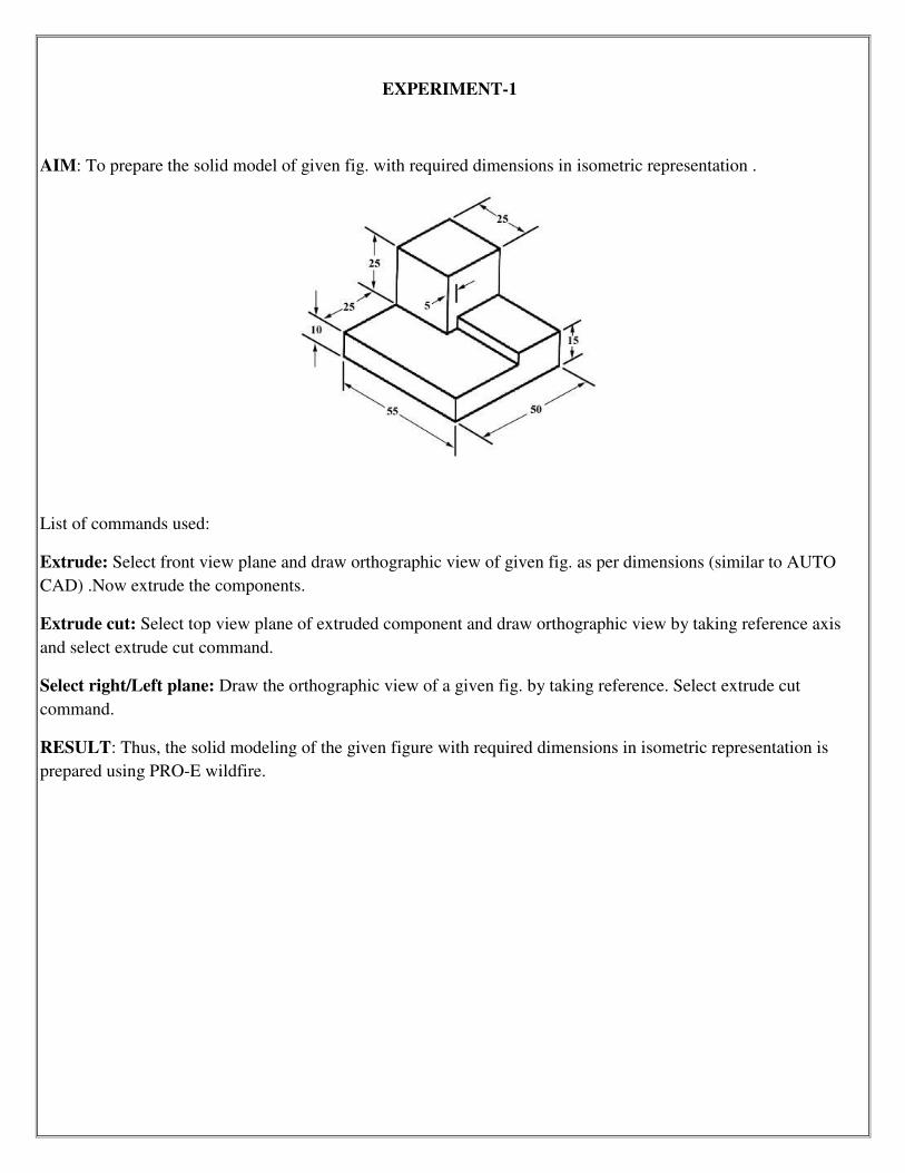
EXPERIMENT-1
AIM: To prepare the solid model of given fig. with required dimensions in isometric representation .
List of commands used:
Extrude: Select front view plane and draw orthographic view of given fig. as per dimensions (similar to AUTO
CAD) .Now extrude the components.
Extrude cut: Select top view plane of extruded component and draw orthographic view by taking reference axis
and select extrude cut command.
Select right/Left plane: Draw the orthographic view of a given fig. by taking reference. Select extrude cut
command.
RESULT: Thus, the solid modeling of the given figure with required dimensions in isometric representation is
prepared using PRO-E wildfire.

EXPERIMENT-2
AIM: To prepare the solid model of given fig. with required dimensions in isometric representation.
Soft ware used: Pro-E wildfire 5.0.
List of commands used:
Extrude: Select front view plane and draw orthographic view of given fig. as per dimensions (similar to AUTO
CAD) .Now extrude the components.
Extrude cut: Select top view plane of extruded component and draw orthographic view by taking reference axis
and select extrude cut command.
Select right/Left plane: Draw the orthographic view of a given fig. by taking reference. Select extrude cut
command.
RESULT: Thus , the solid modeling of the given figure with required dimensions in isometric representation is
prepared using PRO-E wildfire 5.0 .

EXPERIMENT-3
AIM: To prepare the solid model of given fig. with required dimensions in isometric representation .
Soft ware used: Pro-E wildfire 5.0.
List of commands used:
Extrude: Select front view plane and draw orthographic view of given fig. as per dimensions (similar to AUTO
CAD) .Now extrude the components.
Extrude cut: Select top view plane of extruded component and draw orthographic view by taking reference axis
and select extrude cut command.
Select right/Left plane: Draw the orthographic view of a given fig. by taking reference. Select extrude cut
command.
RESULT: Thus , the solid modeling of the given figure with required dimensions in isometric representation is
prepared using PRO-E wildfire.
EXPERIMENT-4

AIM: To prepare the solid model of given fig. with required dimensions in isometric representation .
Soft ware used: Pro-E wildfire 5.0.
List of commands used:
Extrude: Select front view plane and draw orthographic view of given fig. as per dimensions (similar to AUTO
CAD) .Now extrude the components.
Extrude cut: Select top view plane of extruded component and draw orthographic view by taking reference axis
and select extrude cut command.
Select right/Left plane: Draw the orthographic view of a given fig. by taking reference. Select extrude cut
command.
RESULT: Thus , the solid modeling of the given figure with required dimensions in isometric representation is
prepared using PRO-E wildfire.

INTRODUCTION TO ANSYS
ANSYS is a finite element method(FEM) software package. It uses a pre-processor software engine to create
geometry. Then it uses a solution routine to apply load to the meslud geometry. Finally it outputs the desired
results in post processing.
ANSYS is used throughout industry in many engineering disciplines. This software package is used by engineers
that investigates the world trade center collapse in 2001.
At ANSYS , we bring clarity an insight to customers, most complex design challenges through fast , accurate and
reliable simulation .Our technology enables organizations to predict with confidence that their product will thrive
in real world. They trust the software to help , ensure product integrity and drive business success through
innovation.
In ANSYS , we need to be familiar with three of the commands of the main menu:
Pre-processor , solution and post processor.

EXPERIMENT-1
SIMPLE CANTILEVER BEAM
DISCIPLINE: Structural
ANALYSIS TYPE: Static
ELEMENT TYPE: Beam-3
AIM: To find the maximum deflections, shear force, bending moment and draw shear force and bending moment
diagrams.
Preprocessing:
1) Define the discipline:
Preferences > structural > h-method.
2) Define type of element:
Preprocessor (menu) > element type > add / edit/delete.
Add - beam – 2D – elastic – 3
3)Define geometric properties :
Preprocessor > real constants
Enter area = 0.0001 𝑚² Z=8033e-
Height = 0.01m
4) Define material properties :
Material models / structural/ linear/ elastic/ isotropic.
E ͓= 2e5
V = 0.3
Density = 7890
5) Creating beam element
Creating key points

Pre-processor > modeling> create> key points> in active CS
X Y Z
1) 0 ; 0 ; 0
2) 1 ; 0 ; 0
6) Preprocessor > create > lines> straight lines .
Picking menu appears
Pick starting key point 1 and encoding key point.
7) Apply displacement constraints.
Solution > (loads) > apply> structural (displacement) on key points.
Apply “ ALL DOF” at key point 1.
8) Apply load at key point 2.
Solution > (loads) apply> (structural) force / moment > on key points.
Fy= -100N
9) Solve:
Solution > (solve) current LS
Post processing :
General post processing > element table > add > by sequence number > LS2 results > element table data.
Maximum stress in element 1 is 0.600249e9.
Maximum stress in element 10 is 0.60024e8.
Shear force and bending moment diagrams :
General post processor > element table > define table > add user table for item : SFI
By sequence numbers : SM/SC2 user table for item : SFj
By sequence numbers : SM/SC8
User table for item: BMi
By sequence number : SM/SC6

User table for item : BMj
By sequence number : SM/SC12
General post processing > plot results > contour plot > linear results.

EXPERIMENT-2
TRUSS
DISCIPLINE: Structural
ANALYSIS TYPE: Static
ELEMENT TYPE: link 2D spar
PROBLEM DISCRIPTION
AIM: To find out and member force in the link element
Pre processing :
1)Define the discipline :
Preferences > structural type > type > add / edit / delete
Add – link – 2D spar
2) Define the type of element :
Pre processor > element type > add / edit / delete
Add – link - 2D spar
3) define geometric properties
Pre processor > real constants > add
Area = 1 𝑚²
4)define material properties
Pre processor > material models > structural > linear > isotropic
Ex: 2.1∗ 1011 = 2e11.
5)Creating nodes :
Pre processor > modeling > create > elements > nodes
6) Apply displacement constraints :
Solutions > (loads ) apply > (structural ) displacement > on nodes

Pick node 1
Apply ALL DOF
Pick node 4
Apply constant in Uy
Ok
7) Apply loads :
Solution > ( loads ) apply > structural > force / moment > on nodes
Pick node 2
Apply – 90KN Fy direction .
Pick node 3
Apply 120 KN in Fy direction
8) solve:
Solution > solve > current LS
Post processing : (viewing ) results
GPP > list results > element solution > line element table
Element no: Connectivity M.F (KN) SA*L(KN/m2
1 1-2 0 0
2 2-3 75 75
3 3-4 0 0
4 4-5 -82.5 -110
5 5-6 -75 -82.5
6 6-7 -100 -82.5
7 7-8 -10 -75
8 8-1 0 -100
9 7-2 25 -10
10 6-3 12.5 0

EXPERIMENT 3 :
SIMPLY SUPPORTED BEAM
DISCIPLINE: Structural
ANALYSIS: static , H-method
Element type : beam
AIM : To determine the deflection , stress in the following 2D element
Soft ware used : ANSYS 14.0
Pre processing
1)preference – structural H –method
2)define element type
Preprocessor > element type > add/edit / delete > beam 2D elastic > ok
3) preprocessor > real constants > add /edit /delete > area =250mm2
4)pre processor > material properties > material models > structural > linear > elastic > iso tropic
Ex = 2e5
V= 0.3
5) Preprocessor > section > beam > common section > simply supported beam
Sub type = rectangular
Height = 80
Breadth = 40
DMx = 0.193501m
6) create nodes:
Preprocessor > modeling > create > nodes > in active CS
Node1 : X=0.1 Y=0
Node2 : X=0.7 Y=0
Node3: X=1 Y=0

7) create links :
Modeling > create elements > auto numbered > three nodes > ok
8) Apply displacement constraints :
Solution > define loads > apply loads > structural > displacement > on nodes .
Node1: node3 (Vy apply).
9) Apply load :
Preprocessor > define loads > apply loads > structural > force /moment > on nodes
F=15000N
10) Solution > solve < current LS
11) GPP > list results > nodal solutions
Element no UY (strain)
1 0.000
2 -0.41417e-3
3 -0.13472e-2
4 -0.23348e-2
5 -0.29129e-2
6 -0.27497e-2
7 -0.2448e-2
8 -0.11302e-2
9 -0.33789e-2
10 0.000
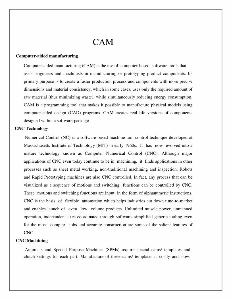
CAM
Computer-aided manufacturing
Computer-aided manufacturing (CAM) is the use of computer-based software tools that
assist engineers and machinists in manufacturing or prototyping product components. Its
primary purpose is to create a faster production process and components with more precise
dimensions and material consistency, which in some cases, uses only the required amount of
raw material (thus minimizing waste), while simultaneously reducing energy consumption.
CAM is a programming tool that makes it possible to manufacture physical models using
computer-aided design (CAD) programs. CAM creates real life versions of components
designed within a software package
CNC Technology
Numerical Control (NC) is a software-based machine tool control technique developed at
Massachusetts Institute of Technology (MIT) in early 1960s. It has now evolved into a
mature technology known as Computer Numerical Control (CNC). Although major
applications of CNC even today continue to be in machining, it finds applications in other
processes such as sheet metal working, non-traditional machining and inspection. Robots
and Rapid Prototyping machines are also CNC controlled. In fact, any process that can be
visualized as a sequence of motions and switching functions can be controlled by CNC.
These motions and switching functions are input in the form of alphanumeric instructions.
CNC is the basis of flexible automation which helps industries cut down time-to-market
and enables launch of even low volume products. Unlimited muscle power, unmanned
operation, independent axes coordinated through software, simplified generic tooling even
for the most complex jobs and accurate construction are some of the salient features of
CNC.
CNC Machining
Automats and Special Purpose Machines (SPMs) require special cams/ templates and
clutch settings for each part. Manufacture of these cams/ templates is costly and slow.

Advantages of CNC
Flexibility
Accuracy
Speed
Simplified fixturing and generic cutting tools
Storage of machining skill in NC programs
Less skilled operators will do
Less fatigue to the operators
G-codes
G-Code, or preparatory code or function, are functions in the Numerical control programming
language. The G-codes are the codes that position the tool and do the actual work, as opposed
to M-codes, that manages the machine; T for tool-related codes. S and F are tool-Speed and
tool-Feed, and finally D-codes for tool compensation. The programming language of
Numerical Control (NC) is sometimes informally called G- code. But in actuality, G-codes
are only a part of the NC-programming language that controls NC and CNC machine tools.
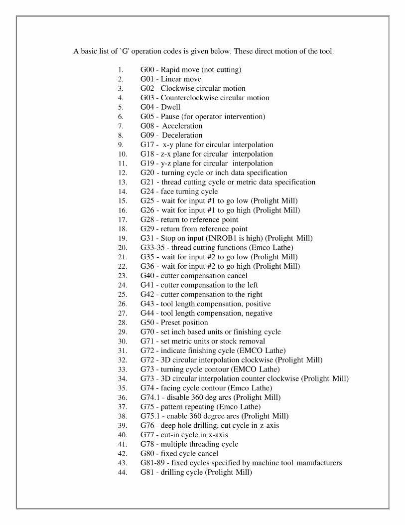
A basic list of `G' operation codes is given below. These direct motion of the tool.
1. G00 - Rapid move (not cutting)
2. G01 - Linear move
3. G02 - Clockwise circular motion
4. G03 - Counterclockwise circular motion
5. G04 - Dwell
6. G05 - Pause (for operator intervention)
7. G08 - Acceleration
8. G09 - Deceleration
9. G17 - x-y plane for circular interpolation
10. G18 - z-x plane for circular interpolation
11. G19 - y-z plane for circular interpolation
12. G20 - turning cycle or inch data specification
13. G21 - thread cutting cycle or metric data specification
14. G24 - face turning cycle
15. G25 - wait for input #1 to go low (Prolight Mill)
16. G26 - wait for input #1 to go high (Prolight Mill)
17. G28 - return to reference point
18. G29 - return from reference point
19. G31 - Stop on input (INROB1 is high) (Prolight Mill)
20. G33-35 - thread cutting functions (Emco Lathe)
21. G35 - wait for input #2 to go low (Prolight Mill)
22. G36 - wait for input #2 to go high (Prolight Mill)
23. G40 - cutter compensation cancel
24. G41 - cutter compensation to the left
25. G42 - cutter compensation to the right
26. G43 - tool length compensation, positive
27. G44 - tool length compensation, negative
28. G50 - Preset position
29. G70 - set inch based units or finishing cycle
30. G71 - set metric units or stock removal
31. G72 - indicate finishing cycle (EMCO Lathe)
32. G72 - 3D circular interpolation clockwise (Prolight Mill)
33. G73 - turning cycle contour (EMCO Lathe)
34. G73 - 3D circular interpolation counter clockwise (Prolight Mill)
35. G74 - facing cycle contour (Emco Lathe)
36. G74.1 - disable 360 deg arcs (Prolight Mill)
37. G75 - pattern repeating (Emco Lathe)
38. G75.1 - enable 360 degree arcs (Prolight Mill)
39. G76 - deep hole drilling, cut cycle in z-axis
40. G77 - cut-in cycle in x-axis
41. G78 - multiple threading cycle
42. G80 - fixed cycle cancel
43. G81-89 - fixed cycles specified by machine tool manufacturers
44. G81 - drilling cycle (Prolight Mill)

45. G82 - straight drilling cycle with dwell (Prolight Mill) 46. G83 - drilling cycle (EMCO Lathe) 47. G83 - peck drilling cycle (Prolight Mill) 48. G84 - taping cycle (EMCO Lathe) 49. G85 - reaming cycle (EMCO Lathe) 50. G85 - boring cycle (Prolight mill) 51. G86 - boring with spindle off and dwell cycle (Prolight
Mill) 52. G89 - boring cycle with dwell (Prolight Mill) 53. G90 - absolute dimension program 54. G91 - incremental dimensions 55. G92 - Spindle speed limit 56. G93 - Coordinate system setting 57. G94 - Feed rate in ipm (EMCO Lathe) 58. G95 - Feed rate in ipr (EMCO Lathe) 59. G96 - Surface cutting speed (EMCO Lathe) 60. G97 - Rotational speed rpm (EMCO Lathe) 61. G98 - withdraw the tool to the starting point or feed per
minute 62. G99 - withdraw the tool to a safe plane or feed per
revolution 63. G101 - Spline interpolation (Prolight Mill)
M-Codes
M-Codes control machine functions and these include,
1. M00 - program stop
2. M01 - optional stop using stop button
3. M02 - end of program
4. M03 - spindle on CW
5. M04 - spindle on CCW
6. M05 - spindle off
7. M06 - tool change
8. M07 - flood with coolant
9. M08 - mist with coolant
10. M08 - turn on accessory #1 (120VAC outlet) (Prolight Mill)
11. M09 - coolant off
12. M09 - turn off accessory #1 (120VAC outlet) (Prolight Mill)
13. M10 - turn on accessory #2 (120VAC outlet) (Prolight Mill)
14. M11 - turn off accessory #2 (120VAC outlet) (Prolight Mill) or tool change
15. M17 - subroutine end
16. M20 - tailstock back (EMCO Lathe)
17. M20 - Chain to next program (Prolight Mill)
18. M21 - tailstock forward (EMCO Lathe)
19. M22 - Write current position to data file (Prolight Mill)
20. M25 - open chuck (EMCO Lathe)
21. M25 - set output #1 off (Prolight Mill)
22. M26 - close chuck (EMCO Lathe)

23. M26 - set output #1 on (Prolight Mill)
24. M30 - end of tape (rewind)
25. M35 - set output #2 off (Prolight Mill)
26. M36 - set output #2 on (Prolight Mill)
27. M38 - put stepper motors on low power standby (Prolight Mill)
28. M47 - restart a program continuously, or a fixed number of times (Prolight Mill)
29. M71 - puff blowing on (EMCO Lathe)
30. M72 - puff blowing off (EMCO Lathe)
31. M96 - compensate for rounded external curves
32. M97 - compensate for sharp external curves
33. M98 - subprogram call
34. M99 - return from subprogram, jump instruction
35. M101 - move x-axis home (Prolight Mill)
36. M102 - move y-axis home (Prolight Mill)
37. M103 - move z-axis home (Prolight Mill
CNC PROGRAMMING
The coordinates are almost exclusively cartesian and the origin is on the workpiece.
For a lathe, the infeed/radial axis is the x-axis, the carriage/length axis is the z-axis. There is no need for a y-axis because the tool moves in a plane through the rotational center of the work. Coordinates on the work piece shown below are relative to the work.
CNC lathe / CNC turning center

CNC lathes are rapidly replacing the older production lathes (multispindle, etc) due to their ease
of setting and operation. They are designed to use modern carbide tooling and fully utilize
modern processes. The part may be designed and the tool paths programmed by the CAD/CAM
process, and the resulting file uploaded to the machine, and once set and trailed the machine
will continue to turn out parts under the occasional supervision of an operator.The machine is
controlled electronically via a computer menu style interface; the program may be modified and
displayed at the machine, along with a simulated view of the process. The setter/operator needs
a high level of skill to perform the process, however the knowledge base is broader compared to
the older production machines where intimate knowledge of each machine was considered
essential. These machines are often set and operated by the same person, where the operator will
supervise a small number of machines (cell).

PLAIN TURNING AND FACING OPERATION
AIM:
To write the part program for component shown in Fig. 01. Assuming the
work piece is Aluminum and the speed is 1200 rpm, feed 20 mm/min and maximum
depth of cut is 1 mm.
a. With Canned cycle
b. Without Canned cycle.
MATERIAL REQUIRED: Aluminum Rod of 30 mm diameter and 80 mm length.
PART DRAWING:
FIGURE: 01
PART PROGRAM:
(A) WITH CANNED CYCLE
N 00 G 21 G 90 <EOB>
N 01 M 03 S
1200 <
EOB>
N 02 G 00 X 30 Z 0 <EOB
>
N 03 G 71 Z -3 X 0 I 1 F 20 <EOB
>
N 04 G 00 X 30 Z 0 <EOB
>
N 05 G 72 X 24 Z -50 I 1 F 20 <EOB
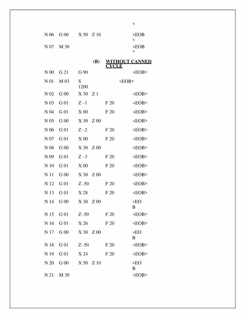
>
N 06 G 00 X 50 Z 10 <EOB
>
N 07 M 30 <EOB>
(B) WITHOUT CANNED CYCLE
N 00 G 21 G 90 <EOB>
N 01 M 03 S
1200
<EOB>
N 02 G 00 X 30 Z 1 <EOB>
N 03 G 01 Z –1 F 20 <EOB>
N 04 G 01 X 00 F 20 <EOB>
N 05 G 00 X 30 Z 00 <EOB>
N 06 G 01 Z –2 F 20 <EOB>
N 07 G 01 X 00 F 20 <EOB>
N 08 G 00 X 30 Z 00 <EOB>
N 09 G 01 Z –3 F 20 <EOB>
N 10 G 01 X 00 F 20 <EOB>
N 11 G 00 X 30 Z 00 <EOB>
N 12 G 01 Z -50 F 20 <EOB>
N 13 G 01 X 28 F 20 <EOB>
N 14 G 00 X 30 Z 00 <EO
B
N 15 G 01 Z -50 F 20 <EOB>
N 16 G 01 X 26 F 20 <EOB>
N 17 G 00 X 30 Z 00 <EO
B
N 18 G 01 Z -50 F 20 <EOB>
N 19 G 01 X 24 F 20 <EOB>
N 20 G 00 X 50 Z 10 <EO
B
N 21 M 30 <EOB>

RESULT:
The program is written and simulated and stored in System No…and file name as…

STEP TURNING OPERATION
AIM:
To write the part program for the component shown in fig 2. assuming work piece as AL the speed
is 1200rpm, feed given is 20mm/min.
(a) Without canned cycle
(b) With canned cycle.
MATERIAL REQUIRED: Aluminum Rod of 30 mm diameter and 80 mm length.
PART DRAWING:
PART PROGRAM: (A) WITHOUT CANNED CYCLE
N 00 G 21 G 90 <EOB>
N 01 M 03 S
1200
<EOB>
N 02 G 04 X 02 <EOB>
N 03 G 00 X 30 Z 00 <EOB>
N 04 G 01 Z -50 F 20 <EOB>
N 05 G 00 X 30 Z 00 <EOB>
N 06 G 01 X 26 F 20 <EOB>
N 07 G 01 Z -50 F 20 <EOB>
N 08 G 00 X 30 Z 00 <EOB>
N 09 G 01 X 24 F 20 <EOB>
Ø3
0
Ø2
4
Ø1
8

N 10 G 01 Z -50 F 20 <EOB>
N 11 G 00 X 30 Z 00 <EOB>
N 12 G 01 X 22 F 20 <EOB>
N 13 G 01 Z -22 F 20 <EOB>
N 14 G 00 X 30 Z 00 <EOB>
N 15 G 01 X 20 F 20 <EOB>
N 16 G 01 Z -22 F 20 <EOB>
N 17 G 00 X 30 Z 00 <EOB>
N 19 G 00 X 50 Z 10 <EOB>
N 20 M 30 <EOB>
( B) WITH CANNED CYCLE:
N 00 G 21 G 90 <EOB>
N 01 M 03 S
1200
<EOB>
N 02 G 04 X 03
<EOB>
N O3 G 00 X 30 Z 00
<EOB>
N 04 G 72 X 24 Z -50 I 01 F 20 <EOB>
N 05 G 72 X 20 Z -22 I 01 F20 <EOB>
N 06 G 00 X 30 Z 00
<EOB>
N 08 X 50 Z 10
<EOB>
N 09 M 30
<EOB>
RESULT:
The program is written and simulated and stored in System No…and file name as…

PATTERN REPEATED CYCLE
AIM:
To write the part program for the component shown in Fig. 3. Assuming work
piece is Aluminum and the speed is 1200 rpm, feed given is 20 mm/min,using
pattern repeated cycle.
MATERIAL REQUIRED: Aluminum Rod of 30 mm diameter and 80 mm length.
PART DRAWING
PART
PROGRAM:
FIGURE. 3.
N 00 G 21 G 90 <EOB>
N 01 M 03 S
1200
<EOB>
N 02 G 04 X 04 <EOB>
N 03 G 00 X 30 Z 00 <EOB>
N 04 G 73 P 05 Q 09 I 01 <EOB>
N 05 G 01 X 18 F 20 <EOB>
N 06 G 01 X 24 Z -22 F 20 <EOB>
N 07 G 01 Z -50 F 20 <EOB>
N 08 G 00 X 30 <EOB>
N 09 G 00 Z 00 <EOB>

N 10 G 00 X 50 Z 05 <EOB>
N 11 M 30 <EOB>
RESULT: The program is written and simulated and stored in System No…and file name
as

THREAD CUTTING
AIM:
To write the part programming for the component shown in Fig 4. Assuming
work piece as Aluminum and the turning speed is 1200 rpm and feed is 20
mm / min and the depth of cut is 1 mm. For thread cutting reduce the speed to
half of the turning speed and pitch is 0.1mm.
MATERIAL REQUIRED: Aluminum Rod of 30 mm diameter and 80 mm length.
PART DRAWING:
PART PROGRAME:
N 00 G 21 G 90 <EOB>
N 01
N 02
M 03
G 00
S
1200
X 30
Z 00
<EOB>
<EOB>
N 03
N 04
N 05
N 06
N 07
N 08
G 01
G 01
G 00
G 72
G 00
M 05
Z -01
X 00
X 30
X 20
X 30
F 20
F 20
Z 00
Z -40
Z 05
I 01
F 20
<EOB>
<EOB>
<EOB>
<EOB>
<EOB>
<EOB>
N 09 T 0202 <EOB>

N 09 M 03 S 600 <EOB>
N 10 G 04 X 02 <EOB>
N 11 G 01 X 20 Z 00 F 20 <EOB>
N 12 G 93 (or) 92 X 20 Z -35 I 0.1 F 01 <EOB>
N 13 G 00 X 30 Z 01 <EOB>
N 14
RESULT:
M 30 <EOB>
The program is written and simulated and stored in System No…and file name as…

CIRCULAR INTER POLATION
AIM:
To write the part programming for the figure shown in Fig.5. speed is 1200 rpm,
feed is 20 mm / min. Assuming work piece as Aluminium.
MATERIAL REQUIRED: Aluminum Rod of 30 mm diameter and 80 mm length.
THEORY:
Circular interpolation is used to simplify the programming of arcs and
circles. It required of four bits of information those are.
The direction of cutter travel (GOZ for cw and G03 is for CCW)
Start point for arc (xs zs) for lathe and (xs, ys) for milling
Center of arc (xl,zl) for lathe and (xl,yl) for milling machine
The final point of the arc except for (xf,zf) for lathe and (xf,yf) for milling.
PART DRAWING:
PART
PROGRAM:
FIGURE.5.
N 00 G 21 G 90 <EOB>
N 01 M 03 S 1200 <EOB>
N 02 G 04 X 04 <EOB>

N 03 G 00 X 30 Z 00 <EOB>
N 04 G 72 X 20 Z -55 I 01 F 20 <EOB>
N 05 G 00 X 30 Z 00 <EOB>
N 06 G 00 X 20 Z 00 <EOB>
N 07 G 01 X 18 F 20 <EOB>

N 08 G 02 X 20 Z -01 K -1 I 0 F 20 <EOB>
N 09 G 00 Z 00 <EOB>
N 10 G 01 X 16 F 20 <EOB>
N 11 G 02 X 20 Z -02 K -2 I 0 F 20 <EOB>
N 12 G 00 Z 00 <EOB>
N 13 G 01 X 14 F 20 <EOB>
N 14 G 02 X 20 Z -03 K -3 I 0 F 20 <EOB>
N 15 G 00 Z 00 <EOB>
N 16 G 01 X 12 F 20 <EOB>
N 17 G 02 X 20 Z -04 K -4 I 0 F 20 <EOB>
N 18 G 00 Z 00 <EOB>
N 19 G 01 X 10 F 20 <EOB>
N 20 G 02 X 20 Z -5 K -5 I 0 F 20 <EOB>
N 21 G 00 Z 00 <EOB>
N 22 G 01 X 8 F 20 <EOB>
N 23 G02 X20 Z-6 K-6 I0 F20 <EOB>
N 24 G00 Z 00 <EOB>
N 25 G 01 X 6 F 20 <EOB>
N 26 G 02 X 20 Z -7 K -7 I 0 F 20 <EOB>
N 27 G 00 Z 00 <EOB>
N 28 G 01 X 4 F 20 <EOB>
N 29 G 02 X 30 Z -8 K-8 I 0 F 20 <EOB>
N 30 G 00 Z 00 <EOB>
N 31 G 01 X 2 F 20 <EOB>
N 32 G 02 X 20 Z -9 K -9 I 0 F 20 <EOB>
N 33 G 00 Z 00 <EOB>
N 34 G 01 X 0 F 20 <EOB>
N 35 G 02 X 20 Z -10 K -10 I 0 F 20 <EOB>
N 36 G 01 Z -31 F 20 <EOB>
N 37 G 01 X 28 F 20 <EOB>

N 38 G 03 X 30 Z -32 K 0 I 2 F 20 <EOB>
N 39 G 00 Z -31 <EOB>
N 40 G 01 X 26 F 20 <EOB>
N 41 G 03 X 30 Z-33 K 0 I 4 F 20 >EOB>
N 42 G 00 Z -31 <EOB>
N 43 G 01 X 24 F 20 <EOB>
N 44 G 03 X 30 Z -34 K 0 I 6 F 20 <EOB>
N 45 G 00 Z –31 <EOB>
N 46 G 01 X 22 F 20 <EOB>
N 47 G 03 X 30 Z -35 K 0 I 8 F 20 <EOB>
N 48 G 00 Z –31 <EOB>
N 49 G 01 X 20 F 20 <EOB>
N 50 G 03 X 30 Z -36 K 0 I 10 F 20 <EOB>
N 51 G 00 X 35 Z 10 <EOB>
N 52 M 30
<EOB>
RESULT:
The program is written and simulated and stored in System No…and file name as…