cabeca a valvulas mesa boogie electra dyne - manual sonigate
DESCRIPTION
Owner’s Manual It’s with our sincere thanks for trusting us with your TONE and our best wishes for all your musical endeavors that we welcome you home. Should you ever need assistance or guidance we’re here to help. You now have in your hands an instrument of limitless ex- pression. Our hope is that it takes you and your playing to new and unimagined places throughout your musical journey. From all of us here at MESA…Enjoy!TRANSCRIPT
Owner’s Manual
Hello from the Tone Farm
Congratulations on your choice of the ELECTRA DYNE™ and welcome to the Mesa/Boo-gie Family! The instrument you have chosen introduces a new realm of performance and versatility to the Single Channel format by combining the best attributes of a simplistic control layout with hidden internal layers of authentic circuit switching. The result is a collection of iconic, vintage-inspired amplifiers built into one chassis you can control with six knobs and a toggle switch. You can also footswitch between these circuits and, though there may be slight compromises, the sounds coexist on one set of controls well enough to turn this Single Channel platform into a Three Mode live performance vehicle. The ELECTRA DYNE, hand-built in Petaluma by MESA (the original Boutique shop) will inevitably redefine what players who follow the Boutique world come to expect from an amplifier.
Our 40 year commitment to excellence along with our solemn promise to musicians - to treat each of them as we ourselves would wish to be treated - guarantees you an experience that will make you feel truly justified in your choice. We’re confident your new amplifier will have you smiling and inspired within minutes of plugging in for the first time. How-ever, what’s really gratifying is that you will be finding new and inspiring sounds years after the price of admission has faded from memory and the ELECTRA DYNE continues to unveil its true worth.
It’s with our sincere thanks for trusting us with your TONE and our best wishes for all your musical endeavors that we welcome you home. Should you ever need assistance or guidance we’re here to help. You now have in your hands an instrument of limitless ex-pression. Our hope is that it takes you and your playing to new and unimagined places throughout your musical journey. From all of us here at MESA…Enjoy!
READ AND FOLLOW INSTRUCTIONS OF PROPER USAGE.
IMPORTANT SAFETY INSTRUCTIONSRead these instructions.
Keep these instructions.
Heed all warnings.
Follow all instructions.
Do not use this apparatus near water.
Clean only with dry cloth.
Do not block any ventilation openings. Install in accordance with the manufacturer’s instructions.
Do not install near any heat sources such as radiators, heat registers, stoves, or other apparatus (including amplifiers) that produce heat.
Do not defeat the safety purpose of the polarized or grounding-type plug. A polarized plug has two blades with one wider than the other. A grounding type plug has two blades and a third grounding prong. The wide blade or the third prong are provided for your safety. If the provided plug does not fit into your outlet, consult an electrician for replacement of the obsolete outlet.
Protect the power cord from being walked on or pinched particularly at plugs, convenience receptacles, and the point where they exit from the apparatus.
Only use attachments/accessories specified by the manufacturer.
Unplug this apparatus during lightning storms or when unused for long periods of time.
Refer all servicing to qualified service personnel. Servicing is required when the apparatus has been damaged in any way, such as power-supply cord or plug is damaged, liquid has been spilled or objects have fallen into the apparatus, the apparatus has been exposed to rain or moisture, does not operate normally, or has been dropped.
To insure proper ventilation always make sure there is at minimum four inches (101.6mm) of space behind the rear of the apparatus. The ventilation should not be impeded by covering the ventilation openings with items, such as newspapers, tablecloths, curtains, etc. Do not impede ventilation by placing objects on top of the apparatus which extend past the rear edge of its cabinet.
No naked flame sources, such as lighted candles, should be placed on the apparatus.
The apparatus shall not be exposed to dripping or splashing and no objects filled with liquids, such as vases, shall be placed on the apparatus.
WARNING: To reduce the risk of fire or electric shock, do not expose this apparatus to rain or moisture.
The AC plug is the mains disconnect. The plug should remain accessible after installation.
WARNING: EU: permission from the Supply Authority is needed before connection.
WARNING: Always make sure proper load is connected before operating the amplifier. Failure to do so could pose a shock hazard and may result in damage to the amplifier.
Do not expose amplifier to direct sunlight or extremely high temperatures.
Always insure the amplifier is properly grounded. Always unplug AC power cord before changing fuse, tubes or removing chassis. Use only same type and rating when replacing fuse.
Avoid direct contact with heated tubes. Keep amplifier away from children.
To avoid damaging your speakers and other playback equipment, turn off the power of all related equipment before making the connections.
Do not use excessive force when handling buttons, switches and controls. Do not use solvents such as benzene or paint thinner to clean the unit.
Always connect to an AC power supply that meets the power supply specifications listed on the rear of the unit. Export models: always insure unit is wired for proper voltage. Make certain grounding conforms with local standards.
YOUR AMPLIFIER IS LOUD! EXPOSURE TO HIGH SOUND VOLUMES MAY CAUSE PERMANENT HEARING DAMAGE!
Your Mesa/Boogie Amplifier is a professional instrument. Please treat it with respect and operate it properly.
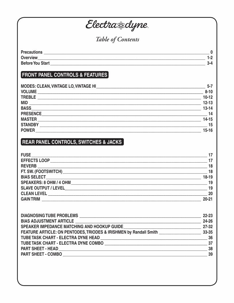
Precautions _______________________________________________________________________________ 0Overview ________________________________________________________________________________ 1-2Before You Start __________________________________________________________________________ 3-4
FRONT PANEL CONTROLS & FEATURES
MODES: CLEAN, VINTAGE LO, VINTAGE HI ____________________________________________________ 5-7VOLUME _______________________________________________________________________________ 8-10TREBLE ______________________________________________________________________________ 10-12MID __________________________________________________________________________________ 12-13BASS _________________________________________________________________________________ 13-14PRESENCE _______________________________________________________________________________ 14MASTER ______________________________________________________________________________ 14-15STANDBY ________________________________________________________________________________ 15POWER _______________________________________________________________________________ 15-16
REAR PANEL CONTROLS, SWITCHES & JACKS
FUSE ____________________________________________________________________________________ 17EFFECTS LOOP ___________________________________________________________________________ 17REVERB _________________________________________________________________________________ 18FT. SW. (FOOTSWITCH) _____________________________________________________________________ 18BIAS SELECT __________________________________________________________________________ 18-19SPEAKERS: 8 OHM / 4 OHM _________________________________________________________________ 19SLAVE OUTPUT / LEVEL____________________________________________________________________ 19CLEAN LEVEL ____________________________________________________________________________ 20GAIN TRIM ____________________________________________________________________________ 20-21
DIAGNOSING TUBE PROBLEMS __________________________________________________________ 22-23BIAS ADJUSTMENT ARTICLE ____________________________________________________________ 24-26SPEAKER IMPEDANCE MATCHING AND HOOKUP GUIDE _____________________________________ 27-32FEATURE ARTICLE: ON PENTODES, TRIODES & IRISHMEN by Randall Smith ____________________ 33-35TUBE TASK CHART - ELECTRA DYNE HEAD ___________________________________________________ 36TUBE TASK CHART - ELECTRA DYNE COMBO _________________________________________________ 37PART SHEET - HEAD _______________________________________________________________________ 38PART SHEET - COMBO _____________________________________________________________________ 39
Table of Contents
PAGE 1
Overview:
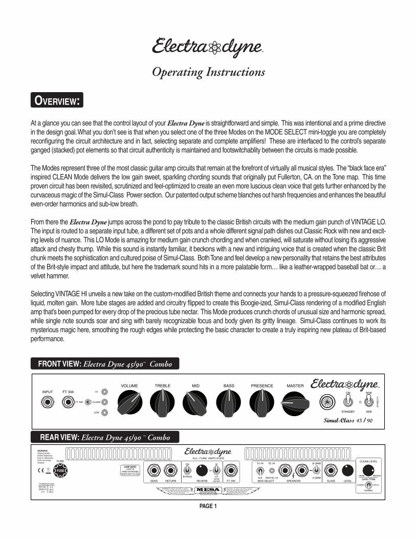
At a glance you can see that the control layout of your Electra Dyne is straightforward and simple. This was intentional and a prime directive in the design goal. What you don’t see is that when you select one of the three Modes on the MODE SELECT mini-toggle you are completely reconfiguring the circuit architecture and in fact, selecting separate and complete amplifiers! These are interfaced to the control’s separate ganged (stacked) pot elements so that circuit authenticity is maintained and footswitchablity between the circuits is made possible.
The Modes represent three of the most classic guitar amp circuits that remain at the forefront of virtually all musical styles. The “black face era” inspired CLEAN Mode delivers the low gain sweet, sparkling chording sounds that originally put Fullerton, CA. on the Tone map. This time proven circuit has been revisited, scrutinized and feel-optimized to create an even more luscious clean voice that gets further enhanced by the curvaceous magic of the Simul-Class Power section. Our patented output scheme blanches out harsh frequencies and enhances the beautiful even-order harmonics and sub-low breath.
From there the Electra Dyne jumps across the pond to pay tribute to the classic British circuits with the medium gain punch of VINTAGE LO. The input is routed to a separate input tube, a different set of pots and a whole different signal path dishes out Classic Rock with new and excit-ing levels of nuance. This LO Mode is amazing for medium gain crunch chording and when cranked, will saturate without losing it’s aggressive attack and chesty thump. While this sound is instantly familiar, it beckons with a new and intriguing voice that is created when the classic Brit chunk meets the sophistication and cultured poise of Simul-Class. Both Tone and feel develop a new personality that retains the best attributes of the Brit-style impact and attitude, but here the trademark sound hits in a more palatable form… like a leather-wrapped baseball bat or… a velvet hammer.
Selecting VINTAGE HI unveils a new take on the custom-modified British theme and connects your hands to a pressure-squeezed firehose of liquid, molten gain. More tube stages are added and circuitry flipped to create this Boogie-ized, Simul-Class rendering of a modified English amp that’s been pumped for every drop of the precious tube nectar. This Mode produces crunch chords of unusual size and harmonic spread, while single note sounds soar and sing with barely recognizable focus and body given its gritty lineage. Simul-Class continues to work its mysterious magic here, smoothing the rough edges while protecting the basic character to create a truly inspiring new plateau of Brit-based performance.
Operating Instructions
FUSE
BYPASS
ON HI
LO
ON
MODEDEFEAT
6L6
EL-34 EL-34 8 OHM
4 OHMSEND RETURN REVERB FT. SW. BIAS SELECT SPEAKERS SLAVE LEVEL
RED=EL 34
LOOP NOTE:LOOP IS
HARD BYPASSEDWHEN NOT IN USE
100/120~50/60 Hz
4 A
4 ASLOBLO
ALL-TUBE AMPLIFIER
FUSE
GAIN TRIM
NORMAL
HI/LOCLEAN
CLEAN LEVEL
TRIM BYPASS
INPUT FT. SW.
CLEAN
HI
LOW
FT. SW.
VOLUME TREBLE MID BASS PRESENCE MASTER
45W
90W
O
STANDBY
ON
Simul-Class 45 / 90
POWER
FRONT VIEW: Electra Dyne 45/90 Combo™
REAR VIEW: Electra Dyne 45/90 Combo™
PAGE 2
Overview: (Continued)
These three classic circuits can be switched through via the included Footswitch and, if settings are crafted with priority in mind, a surprisingly low level of compromise is experienced even while great footswitching performance attained. There may always be some small level of compromise between the sounds, but given the simplicity of navigation and the quality of Tone achieved, the Electra Dyne wins hands down in the most Tone for the least Tweak arena.
A half-power option appears on the POWER SWITCH and gives you a choice of 90 watts of Simul-Class Power – where one pair of the stock 6L6s run in Class AB and one pair run in Extended Class A. 45 watts turns off the middle pair of 6L6s so only the outer two are running. These are the ones with the lowered bias so, while they are still Class AB, their Class A region is extended.
Starting all the way to the left of the Rear Panel (Head Version) reside two features that increase the footswitching flexibility of the ELECTRA DYNE for live performance.
The first is a CLEAN LEVEL TRIM Control that allows you to decrease the output level of the CLEAN Mode in relation to the VINTAGE LO and HI Modes. This helps to fine tune the sounds so that the balance of the Modes can be adjusted over a wider range of volume levels.
The second feature is a Mode specific GAIN TRIM switch located just below (or just above on Combo Version) the CLEAN LEVEL TRIM Control. This 3 position allows you to configure the Modes to best suit either low or high gain styles. Players who need high gain settings in VINTAGE LO and HI can “trim” the gain in the CLEAN to ensure ample headroom for their clean sound, conversely - players who need a sweet, fat rhythm in CLEAN can “trim” the gain in VINTAGE LO and HI for a lower gain Blues sound.
All tube REVERB control rides on the Rear Panel and paints a lush, ambient landscape around these three sounds. This feature enhances not only the chiming CLEAN Mode, but also helps transform the occasionally brash nature of the LO and HI gain circuits into sounds that can travel effortlessly across stylistic boundaries. There is also a HARD BYPASS that removes all REVERB circuitry, including the tube stages, from the signal path for the Brit minded purist who wants the harder hitting dry version untouched by wet hands. With the REVERB circuit engaged, there is a choice between active in all modes and an auto-defeat feature which allows you to use the REVERB on two of the sounds – CLEAN and your choice of LO or HI – should you want to keep either your crunch rhythm or lead sound dry while having your CLEAN still wet. There is also a ¼” jack on the underside of the chassis that responds to tip-to-ground logic should you want to turn the REVERB on and off with a separate (not included) footswitch.
The Rear Panel BIAS SELECT allows you to swap the stock quartet of 6L6 for a quartet of the brighter sounding EL34 type power tubes. This classic British tube delivers greater accentuation of the upper harmonics and produces a low end this is somewhat stripped of sub-lows and therefore can sound tighter for certain styles. We recommend the stock compliment of 6L6 for the greatest versatility and warmth and all three Modes. NOTE: BIAS SELECT switch MUST MATCH THE TUBES IN USE AT ALL TIMES! Failure to comply with this could result in damage to your amplifier that will not be covered under warranty.
EXTERNAL SWITCH jacks on the Rear Panel allow control of the Modes from a remote master switching unit and respond to standard ¼” tip-to-ground latching logic. This feature allows for interfacing the Electra Dyne into a large stage rig where everything is called up remotely under (usually midi) programs in a master switcher.
SPEAKER IMPEDANCE is selected via a Rear Panel mini toggle and provides for two 8 Ohm or two 4 Ohm jacks. Standard MESA cabinets are either an 8 or 4 Ohm load. To use the Electra Dyne with 16 Ohm loads, connect them using the 8 Ohm position. When using two 16 Ohm cabinets, also connect them to the 8 Ohm jacks. Always check that your SPEAKER IMPEDANCE switch is set to match the load in use. Improper matching will either prevent the amplifier from producing full power or cause the amplifier to run hot and wear the power tubes prematurely.
A SLAVE Output is provided to capture the entire sound (both preamp and power section) of the amplifier so that it can feed an effects rack or additional power amplifiers for big venue applications. This feed is a padded-down version of the signal taken from the SPEAKER Output and does not provide any roll-off of top end or other shaping that would be preferable for using the Electra Dyne direct into a recording console.
That covers a global look at the features of the Electra Dyne and you are now ready to get more specific about the controls and their role in shaping the sounds you are looking for.
PAGE 3
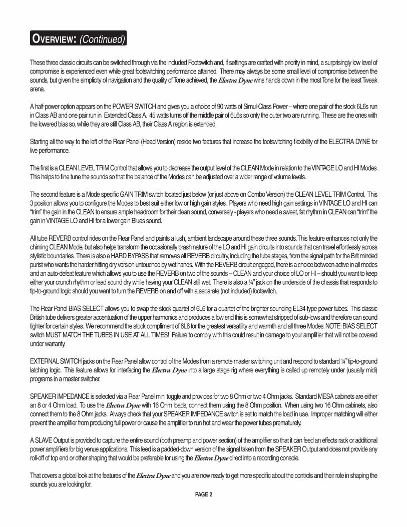
SAMPLE SETTING:
Here’s a quick setting that will give you a quick tour of the basic sound of the Modes in the Electra Dyne.
HELPFUL HINTS:
Cut the cable tie that holds the AC Power Cord to the Rear Tube Cover and connect it to a Grounded AC wall socket.1.
Connect the Stereo ¼” Footswitch Cable to the Front Panel ¼” jack labeled FOOTSWITCH using the supplied Stereo Cable.2.
Set the amplifier (and at least one speaker cabinet) on the floor you will be standing (or sitting on) while playing to complete the 3. coupling circle that occurs. This will make the amplifier sound better, as well as feel better to play, because the sympathetic loop created by the transmission from your hands to the guitar to the amp to your guitar to your hands remains unbroken.
Remember that when you are setting up the controls for Mode Switching with the Footswitch, using the controls in their middle 4. to upper middle ranges (11:00 – 2:00) will provide the best Tone and volume levels between the Modes. This region helps the compromise between sounds remain as small as possible.
The controls are built with ganged (stacked element) pots, which ensures the Modes are true to their classic circuits. This also 5. allows for custom tapers of the controls - which are optimized for both the Tone of the particular Mode – and for the footswitch-able compatibility with the other Modes. May we suggest that you dial by ear and don’t stick firmly to your experience with other amplifiers
Some of the controls used in the CLEAN Mode are fitted with pots that have a very slow taper to aid in footswitchability between 6. Modes. This is so that when you’re using higher VOLUME settings (2:00 -3:00) in VINTAGE HI for lead or crunch rhythm work, and then footswitch back to CLEAN, you will have substantial headroom for clean chording. In CLEAN, the VOLUME and BASS controls in particular utilize this scheme and come on more gradually. Keep this in mind when dialing up sounds in CLEAN and don’t be afraid to set these controls slightly higher (approx. 1/3) to achieve the results you are used to with other amplifiers.
Use the Rear Panel CLEAN LEVEL TRIM Control to decrease the volume (loudness) of the CLEAN Mode in relation to the 7. VINTAGE LO and HI Modes if you find that is too loud for the (lower) volumes you are playing at in smaller venues or at home. This is not an independent MASTER – thus the “TRIM” designation - and can not increase the level of the CLEAN Mode above that set on the Front Panel MASTER Control.
Use the Rear Panel GAIN TRIM Switch to fine tune the gain structure of the Modes for footswitching at times when you would 8. normally set the VOLUME control toward either extreme end of its range… i.e. fully saturated Rock sounds or low gain edge-of-clip Blues sounds. Follow the examples below to get familiar with the uses for the GAIN TRIM switch.
BeFOre YOU STArT:
INPUT FT. SW.
CLEAN
HI
LOW
FT. SW.
VOLUME TREBLE MID BASS PRESENCE MASTER
45W
90W
O
STANDBY
ON
Simul-Class 45 / 90
POWER
PAGE 4
In the first example, the CLEAN Mode would normally be clipped and breaking up with the VOLUME set this high for solo sounds in VINTAGE LO and HI.
In the second example, the VINTAGE LO and HI Modes would normally be too saturated for low gain solo sounds with the VOL-UME set in this range for the desired sound in the CLEAN Mode.
1) For High Gain/Clean applications set VOLUME at 3:00 – 5:00 and select GAIN TRIM: CLEAN to auto-decrease the gain (VOLUME Control) and increase headroom in the CLEAN Mode.
2) For Low Gain/Clean applications set VOLUME at 12:30 – 2:00 and select GAIN TRIM: VINTAGE HI/LO to auto-decrease the gain (VOLUME Control) in the VINTAGE LO and HI Modes.
The bass frequencies in CLEAN are lower than that of the other two Modes and the inclusion of these sub-low frequencies make 9. the BASS control seem more powerful than that of the LO and HI Modes. As mentioned above, steps were taken to minimize the footswitching compromises and the BASS has a more gradual taper for CLEAN. To produce huge low end in CLEAN you will have to run the BASS above 2:00.
For maximum attack, tight low end and aggression, HARD BYPASS the REVERB circuit. The addition of the REVERB TUBE 10. and circuitry warms things up a bit and slows down the attack ever so slightly.
Avoid extreme high settings (4:30-5:30) of the VOLUME and REVERB at the same time – especially in VINTAGE LO and HI - 11. when using the REVERB. These settings will introduce a slight buzzy sound in the REVERB as the extreme gain goes through the spring of the REVERB tank. This is normal and no cause for alarm. It can be easily avoided by simply turning the REVERB down a bit as you approach the top of the VOLUME controls’ range.
Use the 45 watt POWER setting on the Front Panel POWER switch to achieve clipped sounds at the top end of the VOLUME 12. control in the CLEAN Mode.
The TREBLE control is effective at adding additional gain to clipped sounds in CLEAN with the VOLUME cranked (5:30). Try 13. setting the TREBLE higher (2:00 – 3:00) and reduce the PRESENCE and MID to achieve more warmth.
There is substantial top end carried in the MID control along with the midrange frequencies it adjusts. Some like to run the MID 14. higher and then reduce top end at either the TREBLE or PRESENCE controls.
Now that you have an overview of the features of your Electra Dyne, let’s get specific with the modes and controls to help you better understand how to get the sounds you are looking for and apply them to your music.
BeFOre YOU STArT: (Continued)
HELPFUL HINTS: (Continued)
PAGE 5
THE MODES:
While the Electra Dyne appears to most as a simple Single Channel amp, the sparse Front Panel layout hides a vault of circuitry that gives you the power and performance of a Three Channel footswitching amplifier. The three Modes found on the Mode Select mini toggle are each completely separate preamps. They share some of the same tube stages but the signal path and circuitry changes radically when you change from mode to mode. The Electra Dyne ushers in a new era of powerful gig-ability combined with interface simplicity by using ganged (stacked element) pots so that one row of controls can adjust more than one circuit. Custom designed tapers on these pots allow a surprising amount of independence between the Modes. Though there will likely be some settings that create compromises on one or more of the sounds for some – with the controls set in their medium ranges - most players discover a high degree of success switching across the Modes in performance situations. The Electra Dyne was created to fit the needs of a certain player profile… namely those who want to keep their tweaking to a minimum and still maintain as much flexibility as possible. For these guitarists the Electra Dyne creates a whole new realm of easy to dial choices that can be footswitched between without losing that set-it-and-forget-it attitude.
CLEAN:
This is the lowest gain of the three Modes in the Electra Dyne and is based on the classic California “black face” era circuits. It also draws heavily from our MARK I and MARK V Boogie clean modes - where it inherits the sweetness and springy, bouncy attack charac-
teristics. This Mode is aimed at vintage-inspired clean rhythm playing and produces sparkling top end harmonics, articulate but never harsh mids and deep fundamental low end that breathes with three-dimensional air.
Lower settings of the VOLUME control (10:30 – 1:30) will allow more of the top end harmonics to slip through the circuit and produce a stripped, skinny sound that is perfect for R&B and Country styles. As the VOLUME is increased past this range, more rich low mids and bass will start to appear, rounding out and filling in the sound. This range is great for Rock clean rhythm sounds where more punch and attitude are in order. With the VOLUME
maxed (5:30) the sound is fat with low mid girth and, depending on the pickups being used, headroom is minimal and you are most likely going to experience some tube clip in the preamp. If the amp is being played loud you may be clipping both the preamp and the power section. If you wish to emphasize this clip characteristic and really get things breaking up in the CLEAN Mode switch the POWER switch down to 45 watts and you will attain more clip at a lower overall volume level.
The taper of the pot used for the VOLUME control in the CLEAN Mode is very slow and gain is increased very gradually from the bottom of the pot (7:30) throughout the first 2/3 of its taper (2:00). Above this range (2:30 – 5:30) gain starts to increase more rapidly and there is somewhat less resolution available as the gain fills in the sound. This is necessary to allow for higher settings of the VOLUME control in VINTAGE LO and VINTAGE HI Modes – where most players find their favorite higher gain sounds – and still create a viable footswitching scenario. Thanks to this slow taper in the CLEAN VOLUME pot you can have a saturated lead sound in HI, an aggressive ROCK crunch rhythm in LO, and still have enough headroom available for a nice sweet clean sound in the CLEAN Mode. Most players have good luck making all three Modes work by setting the VOLUME control somewhere in the 1:00 – 3:00 range. This range will be affected by pickup strength and string gauge as well.
VINTAGE LO:
This Mode makes the biggest leap in circuit architecture and jumps across the Atlantic to pay tribute to the best of the classic Brit crunch. LO takes a big step up from CLEAN on the gain scale, but in the greater scheme of the entire amp, it’s the pivotal in-between
mode that segues from clean to high gain sounds.
FrONT PANeL: CONTrOLS & FeATUreS
CLEAN
HI
LOW
FT. SW.
CLEAN
HI
LOW
FT. SW.
PAGE 6
FrONT PANeL: CONTrOLS & FeATUreS (Continued)
VINTAGE LO: (Continued) Lower settings of the VOLUME control will produce sounds ranging from a mid-focus, punchy clean (9:00 – 10:30) to iconic Brit Rock crunch (ala AC/DC) in the 11:00 – 1:30 region. From there gain starts to come on faster as you crank up the VOLUME control and tour through some great mildly-saturated Blues sounds (1:30 – 3:00) and finally, wind it up all the way to a burning vintage lead voice (3:15 – 5:30). VINTAGE LO is possibly the most iconic sound in the Electra Dyne and various renditions of this circuit are probably the most recorded sounds in Classic Rock and Roll.
However, far from an imitation of this circuit, the Electra Dyne preamp has been given a huge dose of magic in many areas (some trade secrets that we can’t speak of) and the sound, feel on the strings and uncompromising build quality far exceed what you will ever find in an overpriced vintage relic. This preamp also feeds our patented Simul-Class™ power section! This heaping-helping of sonic super-sauce makes this classic-inspired preamp come to life in a sweet and soulful way no amp from either side of the Atlantic ever has before. Whether you load this hyper-tuned harness with EL-34’s for a skinnier Brit clip or you leave the stock quartet of 6L6s in for a fuller voice, Simul serves up a new frontier of expressive sounds… definitely English in heritage, but pure MESA in performance.
VINTAGE HI:
This Mode pays tribute to the modified British circuits that began to sprout up in the early 80’s in the aftermath of our MARK I and MARK II amplifiers. The MARK I Boogies had been around long enough to get people re-thinking what an American amp was - and
some began wondering what that same treatment would do to a stock U.K. circuit. Mod-men in Southern California started adding more tube stages - and more gain - to the stock Brit circuits of the day and created another iconic sound from England by way of Los Angeles.
We followed this line of thinking for the Electra Dyne, but took the modified theme to every area of the circuit – as we always do – to improve focus, musicality, feel and switchable performance and here the modified Brit sound reaches a new pinnacle. This rendition can cross musical boundaries where its predecessors could not, sounding
violin sweet or, with a twist of a knob unleash a fire-breathing monster. It’s touch sensitive and extremely dynamic at the low end of the spectrum and retains incredible focus and definition at higher gain settings.
VINTAGE HI produces the most gain of the three Modes in the Electra Dyne and would be considered by most the lead Mode, but for today’s heavier music, this is also the go-to Mode for crunch rhythm as well. However, before this high range begins, where layers of tight gain saturate the notes completely, HI picks up a little below where the highest region of VINTAGE LO leaves off.
In this range of the VOLUME control (9:00 – 12:00) HI purrs with a creamy - yet still percussive - blend of subtle saturation and in-stant dynamics. This region is perfect for soulful Blues rhythm or solo work and interfaces beautifully with the lush ambience of the REVERB. This range is also great for the non-footswitching crowd that prefers backing off and rolling up on the guitar’s Volume knob for their clean/drive sounds. Here the instruments’ personality remains intact and it can double for a pushed clean that has more low mid body and girth than would a similar setting in VINTAGE LO.
Dialing up from there on the VOLUME introduces more saturation and the notes begin to hang with harmonic complexity and increased sustain. This range (12:30 – 2:30) is where most rock soloists will find the best blend of tight attack mixed with voice-like sustain. Here the strings feel easy to play and there is ample gain to create virtually any texture and color you wish using the TREBLE and PRESENCE as your attack/bright compass and the MID and Bass to round things out and add body.
NOTE: There is a substantial amount of upper harmonic content in this region (anywhere above 1:30 on up to 5:30) and some pickups showcase/handle this better than others. Higher output humbucking pickups tend to benefit from this layer of harmonics –sounding more open and three-dimensional. Weaker humbuckers and single coils – especially in the bridge position – can get thin and edgy or buzzy as the top end loses the definition and they don’t have quite the low-end body to add balance this top end spectrum.
CLEAN
HI
LOW
FT. SW.
PAGE 7
FrONT PANeL: CONTrOLS & FeATUreS (Continued)
You will have to experiment with your individual guitar and learn how its output and EQ are interpreted by the gain available in this higher range. If you discover that it is too bright for your application, may we suggest running the TREBLE and PRESENCE rather low. If these low settings interfere with your Channel switching needs, might we suggest listening to a different guitar with hotter pick-ups or trying some different pickups in your instrument. You might discover a whole new world of sounds that are more focused and cohesive and that respond to amp gain in a whole different way. Generally speaking, as the output goes up with more windings, the top end recedes and a warmer sound appears - one with a more forward midrange and richer low end - as the dominant character. This will enable you to use the full range of TREBLE and PRESENCE to achieve sounds that are much more balanced and open without introducing thinness or buzz on the top.
Some players prefer to alter the way their guitar hits the first in the string of tubes by introducing an overdrive pedal into the signal path to deal with the lack of focus resulting from weaker, more vintage style pickups. This will usually lop off the top end and add gain in the midrange, adding focus to the notes, albeit in a different way. This is one way of dealing with the situation but it does alter the delicate and magical relationship between the guitar’s magnetic field and the grid of the first preamp tube. Some like the result and for those we are pleased that such a quick remedy is available. This will not cause any harm to the Electra Dyne and is a perfectly fine solution.
For those who prefer the purity of the pickup-straight-to-tube connection (we certainly do) and its symbiotic relationship that retains the greatest dynamic/harmonic content, a little more experimentation may be required to achieve the golden note.
The highest range of the VOLUME (2:30 – 5:30) is all about singing, searing gain. Here the attack is more compressed and a flow of liquid harmonic overdrive pours forth in a wall of sound. Forget about the Blues or any other threshold of drive style, this sound is about grind and shred. Rhythm sounds here definitely need a hot pickup to handle the fury and turn it into tight crunch. Solo sounds soar with harmonic layers that stack up to the stratosphere and sustain without end.
This type and amount of gain sets the stage perfectly for notes to jump harmonics in octave increments and feedback in a continu-ously morphing display of top end complexity and nuance. Again use the TREBLE and PRESENCE to shape the basic identity of the sound and then fill it in to taste with the MID and BASS. Keep in mind that the MID control carries a substantial amount of top end that is different (slightly lower) than that of the TREBLE control and you can really fine tune the voice of lead (and crunch rhythm) sounds by trading “a little of this with a little of that” from these closely related controls.
The higher region of the VINTAGE HI Mode showcases the difference in the frequency of low end between the CLEAN Mode and VINTAGE LO and HI. The two gain Modes utilize a higher frequency of bottom end and therefore can put much more of it to use without getting overwhelmed and flubby. This higher low has a resonant thump that hits hard and punches in the chest - as opposed to the sub-low pant-leg-flap that is dominant in the CLEAN - where lower bottom end is needed to produce rich air and breathing three-dimensionality. So don’t hesitate to dial in a bit more of this higher low end. It won’t slow down the attack on single note solo sounds or get bloated on crunch rhythm work. It stays tightly glued to the notes (chords) and hits in an aggressive, focused way.
This difference is yet another way that the two VINTAGE gain Modes come together with CLEAN to create the an amazing platform for expression, the sweetest cleans sharing the chassis with the ultimate tight, aggressive Rock thump. No matter what your into, even if this higher range is not your main bag, it’s fun to check out the wild and woolly world created by this radical high gain Mode. Enjoy!
PAGE 8
FrONT PANeL: CONTrOLS
Now that you have a better understanding of the Modes, let’s take a look at the individual controls and how they interact to create the sounds you are looking for.
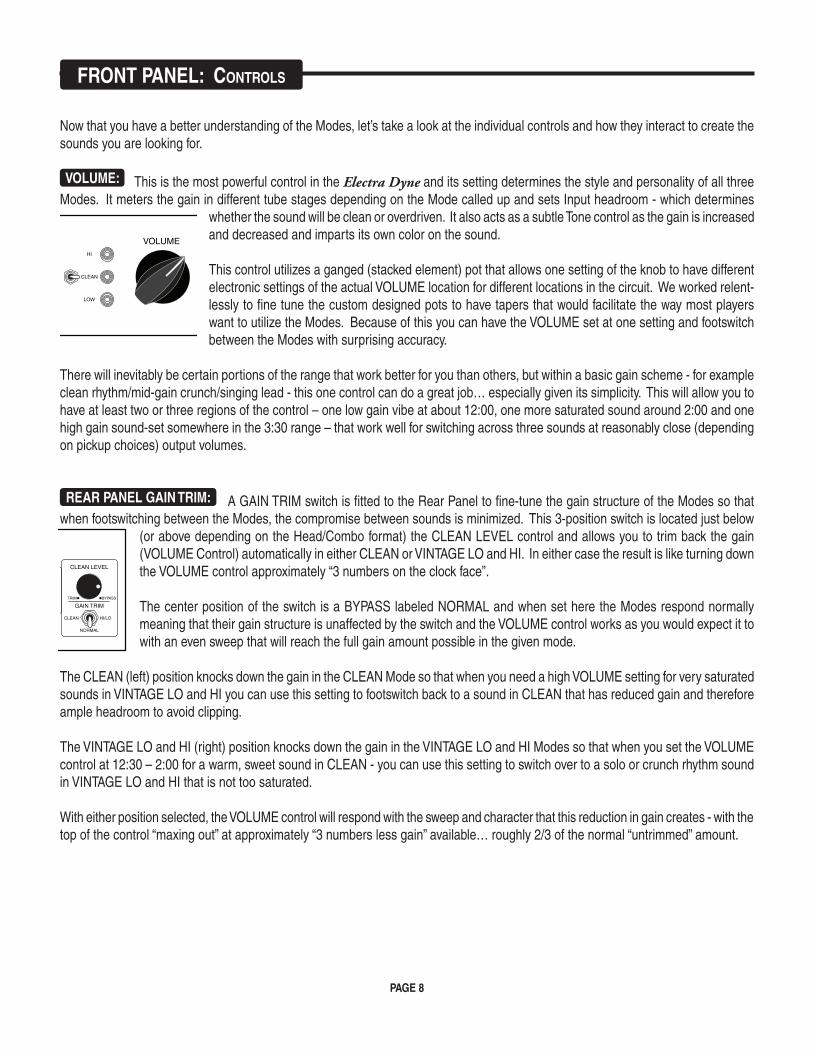
VOLUME: This is the most powerful control in the Electra Dyne and its setting determines the style and personality of all three Modes. It meters the gain in different tube stages depending on the Mode called up and sets Input headroom - which determines
whether the sound will be clean or overdriven. It also acts as a subtle Tone control as the gain is increased and decreased and imparts its own color on the sound.
This control utilizes a ganged (stacked element) pot that allows one setting of the knob to have different electronic settings of the actual VOLUME location for different locations in the circuit. We worked relent-lessly to fine tune the custom designed pots to have tapers that would facilitate the way most players want to utilize the Modes. Because of this you can have the VOLUME set at one setting and footswitch between the Modes with surprising accuracy.
There will inevitably be certain portions of the range that work better for you than others, but within a basic gain scheme - for example clean rhythm/mid-gain crunch/singing lead - this one control can do a great job… especially given its simplicity. This will allow you to have at least two or three regions of the control – one low gain vibe at about 12:00, one more saturated sound around 2:00 and one high gain sound-set somewhere in the 3:30 range – that work well for switching across three sounds at reasonably close (depending on pickup choices) output volumes.
REAR PANEL GAIN TRIM: A GAIN TRIM switch is fitted to the Rear Panel to fine-tune the gain structure of the Modes so that when footswitching between the Modes, the compromise between sounds is minimized. This 3-position switch is located just below
(or above depending on the Head/Combo format) the CLEAN LEVEL control and allows you to trim back the gain (VOLUME Control) automatically in either CLEAN or VINTAGE LO and HI. In either case the result is like turning down the VOLUME control approximately “3 numbers on the clock face”.
The center position of the switch is a BYPASS labeled NORMAL and when set here the Modes respond normally meaning that their gain structure is unaffected by the switch and the VOLUME control works as you would expect it to with an even sweep that will reach the full gain amount possible in the given mode.
The CLEAN (left) position knocks down the gain in the CLEAN Mode so that when you need a high VOLUME setting for very saturated sounds in VINTAGE LO and HI you can use this setting to footswitch back to a sound in CLEAN that has reduced gain and therefore ample headroom to avoid clipping.
The VINTAGE LO and HI (right) position knocks down the gain in the VINTAGE LO and HI Modes so that when you set the VOLUME control at 12:30 – 2:00 for a warm, sweet sound in CLEAN - you can use this setting to switch over to a solo or crunch rhythm sound in VINTAGE LO and HI that is not too saturated.
With either position selected, the VOLUME control will respond with the sweep and character that this reduction in gain creates - with the top of the control “maxing out” at approximately “3 numbers less gain” available… roughly 2/3 of the normal “untrimmed” amount.
INPUT FT. SW.
CLEAN
HI
LOW
FT. SW.
VOLUME TREBLE MID BASS PRESENCE MASTER
45W
90W
O
STANDBY
ON
Simul-Class 45 / 90
POWER
FUSE
BYPASS
ON HI
LO
ON
MODEDEFEAT
6L6
EL-34 EL-34 8 OHM
4 OHMSEND RETURN REVERB FT. SW. BIAS SELECT SPEAKERS SLAVE LEVEL
RED=EL 34
LOOP NOTE:LOOP IS
HARD BYPASSEDWHEN NOT IN USE
100/120~50/60 Hz
4 A
4 ASLOBLO
ALL-TUBE AMPLIFIER
FUSE
GAIN TRIM
NORMAL
HI/LOCLEAN
CLEAN LEVEL
TRIM BYPASS
PAGE 9
FrONT PANeL: CONTrOLS (Continued)
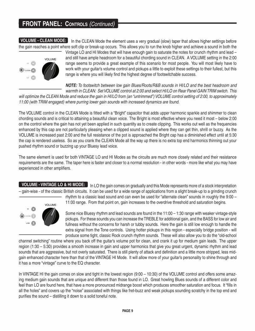
VOLUME - CLEAN MODE: In the CLEAN Mode the element uses a very gradual (slow) taper that allows higher settings before the gain reaches a point where soft clip or break-up occurs. This allows you to run the knob higher and achieve a sound in both the
Vintage LO and HI Modes that will have enough gain to saturate the notes for crunch rhythm and lead – and still have ample headroom for a beautiful chording sound in CLEAN. A VOLUME setting in the 2:00 range seems to provide a great example of this scenario for most people. You will most likely have to work with your guitar’s volume control and pickups a little to exploit these settings to their fullest, but this range is where you will likely find the highest degree of footswitchable success.
NOTE: To footswitch between low gain Blues/Roots/R&B sounds in HI/LO and the best headroom and warmth in CLEAN: Set VOLUME control at 2:00 and select HI/LO on Rear Panel GAIN TRIM switch. This
will optimize the CLEAN Mode and reduce the gain in HI/LO from (an “untrimmed”) VOLUME control setting of 2:00, to approximately 11:00 (with TRIM engaged) where purring lower gain sounds with increased dynamics are found.
The VOLUME control in the CLEAN Mode is fitted with a “Bright” capacitor that adds upper harmonic sparkle and shimmer to clean chording sounds and is critical to attaining a beautiful clean voice. The Bright is most effective where you need it most – below 2:00 on the control where the gain has not yet been applied in such quantity as to create clipping. This works out well as the frequencies enhanced by this cap are not particularly pleasing when a clipped sound is applied where they can get thin, shrill or buzzy. As the VOLUME is increased past 2:00 and the full resistance of the pot is approached the Bright cap has a diminished effect until at 5:30 the cap is rendered useless. So as you crank the CLEAN Mode all the way up there is no extra top end harmonics thinning out your pushed rhythm sound or buzzing up your Bluesy lead voice.
The same element is used for both VINTAGE LO and HI Modes as the circuits are much more closely related and their resistance requirements are the same. The taper here is faster and closer to a normal resolution - in other words - more like what you may have experienced in other amplifiers.
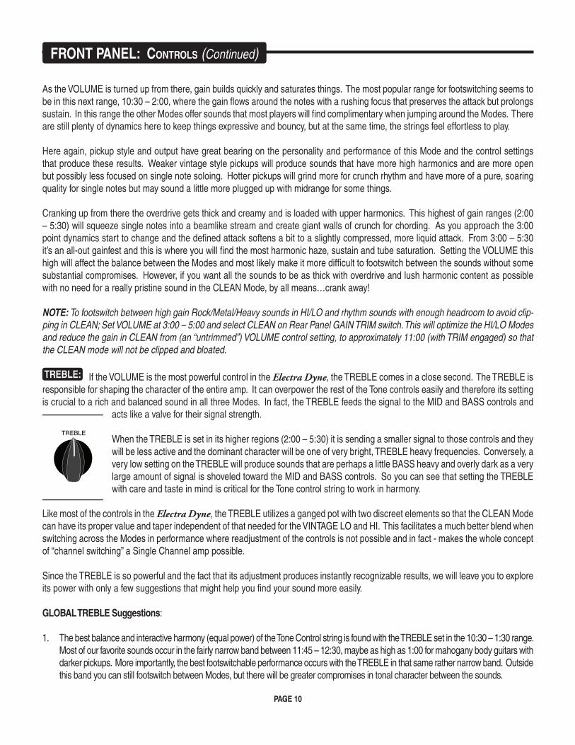
VOLUME - VINTAGE LO & HI MODE: In LO the gain comes on gradually and this Mode represents more of a stock interpretation – gain-wise - of the classic British circuits. It can be used for a wide range of applications from a slight break-up to a grinding crunch
rhythm to a classic lead sound and can even be used for “alternate clean” sounds in roughly the 9:00 – 11:00 range. From that point on, gain increases to the overdrive threshold and saturation begins.
Some nice Bluesy rhythm and lead sounds are found in the 11:00 – 1:30 range with weaker vintage-style pickups. For these sounds you can increase the TREBLE for additional gain, and the BASS for low air and fullness without the concerns for harsh or tubby sounds. Here the gain is still low enough to handle the extra signal from the Tone controls. Using hotter pickups in this region - especially bridge position - will produce some tight, classic Rock crunch rhythm sounds. These will also allow you to do the “old-school
channel switching” routine where you back off the guitar’s volume pot for clean, and crank it up for medium gain leads. The upper region (1:30 – 5:30) provides a smooth increase in gain and upper harmonics that give you great urgent, dynamic rhythm and lead sounds that are aggressive, but not overly saturated. There is still plenty of attack and definition and a little more stripped, less mid-gain enhanced character here than that of the VINTAGE HI Mode. It will allow more of your guitar’s personality to shine through and it has a more “vintage” curve to the EQ character.
In VINTAGE HI the gain comes on slow and tight in the lowest region (9:00 – 10:30) of the VOLUME control and offers some amaz-ing medium gain sounds that are unique and different than those found in LO. Great howling Blues sounds of a different color and feel than LO are found here, that have a more pronounced midrange boost which produces smoother saturation and focus. It “fills in all the holes” and covers up the “noise” associated with things like fret-buzz and weak pickups sounding scratchy in the top end and purifies the sound – distilling it down to a solid toneful note.
CLEAN
HI
LO
VOLUME
CLEAN
HI
LOW
VOLUME
PAGE 10
As the VOLUME is turned up from there, gain builds quickly and saturates things. The most popular range for footswitching seems to be in this next range, 10:30 – 2:00, where the gain flows around the notes with a rushing focus that preserves the attack but prolongs sustain. In this range the other Modes offer sounds that most players will find complimentary when jumping around the Modes. There are still plenty of dynamics here to keep things expressive and bouncy, but at the same time, the strings feel effortless to play.
Here again, pickup style and output have great bearing on the personality and performance of this Mode and the control settings that produce these results. Weaker vintage style pickups will produce sounds that have more high harmonics and are more open but possibly less focused on single note soloing. Hotter pickups will grind more for crunch rhythm and have more of a pure, soaring quality for single notes but may sound a little more plugged up with midrange for some things.
Cranking up from there the overdrive gets thick and creamy and is loaded with upper harmonics. This highest of gain ranges (2:00 – 5:30) will squeeze single notes into a beamlike stream and create giant walls of crunch for chording. As you approach the 3:00 point dynamics start to change and the defined attack softens a bit to a slightly compressed, more liquid attack. From 3:00 – 5:30 it’s an all-out gainfest and this is where you will find the most harmonic haze, sustain and tube saturation. Setting the VOLUME this high will affect the balance between the Modes and most likely make it more difficult to footswitch between the sounds without some substantial compromises. However, if you want all the sounds to be as thick with overdrive and lush harmonic content as possible with no need for a really pristine sound in the CLEAN Mode, by all means…crank away!
NOTE: To footswitch between high gain Rock/Metal/Heavy sounds in HI/LO and rhythm sounds with enough headroom to avoid clip-ping in CLEAN; Set VOLUME at 3:00 – 5:00 and select CLEAN on Rear Panel GAIN TRIM switch. This will optimize the HI/LO Modes and reduce the gain in CLEAN from (an “untrimmed”) VOLUME control setting, to approximately 11:00 (with TRIM engaged) so that the CLEAN mode will not be clipped and bloated.
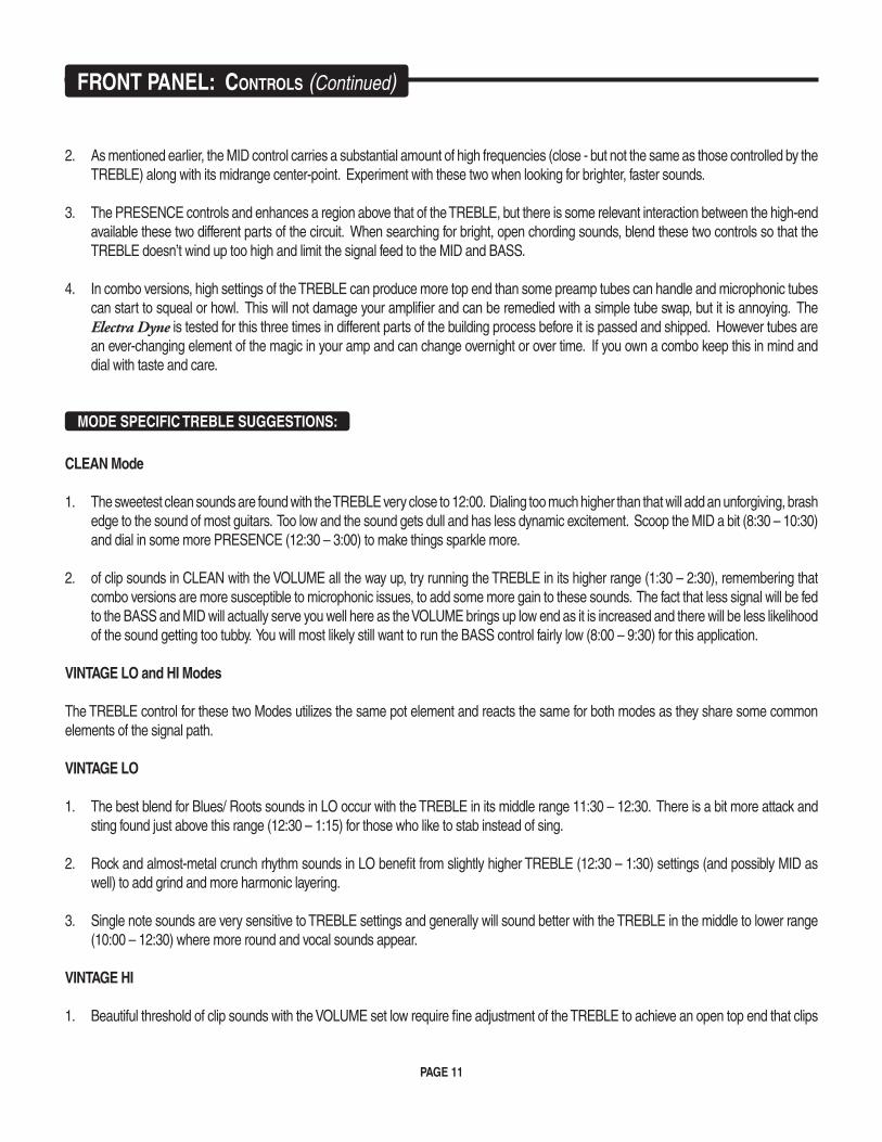
TREBLE: If the VOLUME is the most powerful control in the Electra Dyne, the TREBLE comes in a close second. The TREBLE is responsible for shaping the character of the entire amp. It can overpower the rest of the Tone controls easily and therefore its setting is crucial to a rich and balanced sound in all three Modes. In fact, the TREBLE feeds the signal to the MID and BASS controls and
acts like a valve for their signal strength.
When the TREBLE is set in its higher regions (2:00 – 5:30) it is sending a smaller signal to those controls and they will be less active and the dominant character will be one of very bright, TREBLE heavy frequencies. Conversely, a very low setting on the TREBLE will produce sounds that are perhaps a little BASS heavy and overly dark as a very large amount of signal is shoveled toward the MID and BASS controls. So you can see that setting the TREBLE with care and taste in mind is critical for the Tone control string to work in harmony.
Like most of the controls in the Electra Dyne, the TREBLE utilizes a ganged pot with two discreet elements so that the CLEAN Mode can have its proper value and taper independent of that needed for the VINTAGE LO and HI. This facilitates a much better blend when switching across the Modes in performance where readjustment of the controls is not possible and in fact - makes the whole concept of “channel switching” a Single Channel amp possible.
Since the TREBLE is so powerful and the fact that its adjustment produces instantly recognizable results, we will leave you to explore its power with only a few suggestions that might help you find your sound more easily.
GLOBAL TREBLE Suggestions:
The best balance and interactive harmony (equal power) of the Tone Control string is found with the TREBLE set in the 10:30 – 1:30 range. 1. Most of our favorite sounds occur in the fairly narrow band between 11:45 – 12:30, maybe as high as 1:00 for mahogany body guitars with darker pickups. More importantly, the best footswitchable performance occurs with the TREBLE in that same rather narrow band. Outside this band you can still footswitch between Modes, but there will be greater compromises in tonal character between the sounds.
FrONT PANeL: CONTrOLS (Continued)
INPUT FT. SW.
CLEAN
HI
LOW
FT. SW.
VOLUME TREBLE MID BASS PRESENCE MASTER
45W
90W
O
STANDBY
ON
Simul-Class 45 / 90
POWER
PAGE 11
As mentioned earlier, the MID control carries a substantial amount of high frequencies (close - but not the same as those controlled by the 2. TREBLE) along with its midrange center-point. Experiment with these two when looking for brighter, faster sounds.
The PRESENCE controls and enhances a region above that of the TREBLE, but there is some relevant interaction between the high-end 3. available these two different parts of the circuit. When searching for bright, open chording sounds, blend these two controls so that the TREBLE doesn’t wind up too high and limit the signal feed to the MID and BASS.
In combo versions, high settings of the TREBLE can produce more top end than some preamp tubes can handle and microphonic tubes 4. can start to squeal or howl. This will not damage your amplifier and can be remedied with a simple tube swap, but it is annoying. The Electra Dyne is tested for this three times in different parts of the building process before it is passed and shipped. However tubes are an ever-changing element of the magic in your amp and can change overnight or over time. If you own a combo keep this in mind and dial with taste and care.
MODE SPECIFIC TREBLE SUGGESTIONS:
CLEAN Mode
The sweetest clean sounds are found with the TREBLE very close to 12:00. Dialing too much higher than that will add an unforgiving, brash 1. edge to the sound of most guitars. Too low and the sound gets dull and has less dynamic excitement. Scoop the MID a bit (8:30 – 10:30) and dial in some more PRESENCE (12:30 – 3:00) to make things sparkle more.
of clip sounds in CLEAN with the VOLUME all the way up, try running the TREBLE in its higher range (1:30 – 2:30), remembering that 2. combo versions are more susceptible to microphonic issues, to add some more gain to these sounds. The fact that less signal will be fed to the BASS and MID will actually serve you well here as the VOLUME brings up low end as it is increased and there will be less likelihood of the sound getting too tubby. You will most likely still want to run the BASS control fairly low (8:00 – 9:30) for this application.
VINTAGE LO and HI Modes
The TREBLE control for these two Modes utilizes the same pot element and reacts the same for both modes as they share some common elements of the signal path.
VINTAGE LO
The best blend for Blues/ Roots sounds in LO occur with the TREBLE in its middle range 11:30 – 12:30. There is a bit more attack and 1. sting found just above this range (12:30 – 1:15) for those who like to stab instead of sing.
Rock and almost-metal crunch rhythm sounds in LO benefit from slightly higher TREBLE (12:30 – 1:30) settings (and possibly MID as 2. well) to add grind and more harmonic layering.
Single note sounds are very sensitive to TREBLE settings and generally will sound better with the TREBLE in the middle to lower range 3. (10:00 – 12:30) where more round and vocal sounds appear.
VINTAGE HI
Beautiful threshold of clip sounds with the VOLUME set low require fine adjustment of the TREBLE to achieve an open top end that clips 1.
FrONT PANeL: CONTrOLS (Continued)
PAGE 12
sweetly and doesn’t “gack” on dynamic plucks of the string. This will usually occur with most guitars in the narrow 11:45 – 12:15 range. When this balance is achieved it is possible to roll back on the guitar’s volume pot and have a nice blend for cleaner work.
Higher gain chording sounds can tolerate slightly higher (12:30 – 2:00) TREBLE settings to bring out aggressiveness and chirping har-2. monics. Here again the higher settings of the VOLUME control add low girth and compression that balances out the slightly lower signal feed to the MID and BASS.
Though HI is less sensitive than the LO Mode to higher TREBLE settings for high gain single note solo sounds, there is still some benefit in 3. applying it with taste and finesse. Like LO, the warmest and most cohesive sounds will occur with the TREBLE in the 11:00 – 1:30 range. Above that, the layering of harmonics will create the possibility for detachment of the top end from the body of the notes and thinness. It may be necessary to roll off the PRESENCE substantially when higher TREBLE settings are needed.
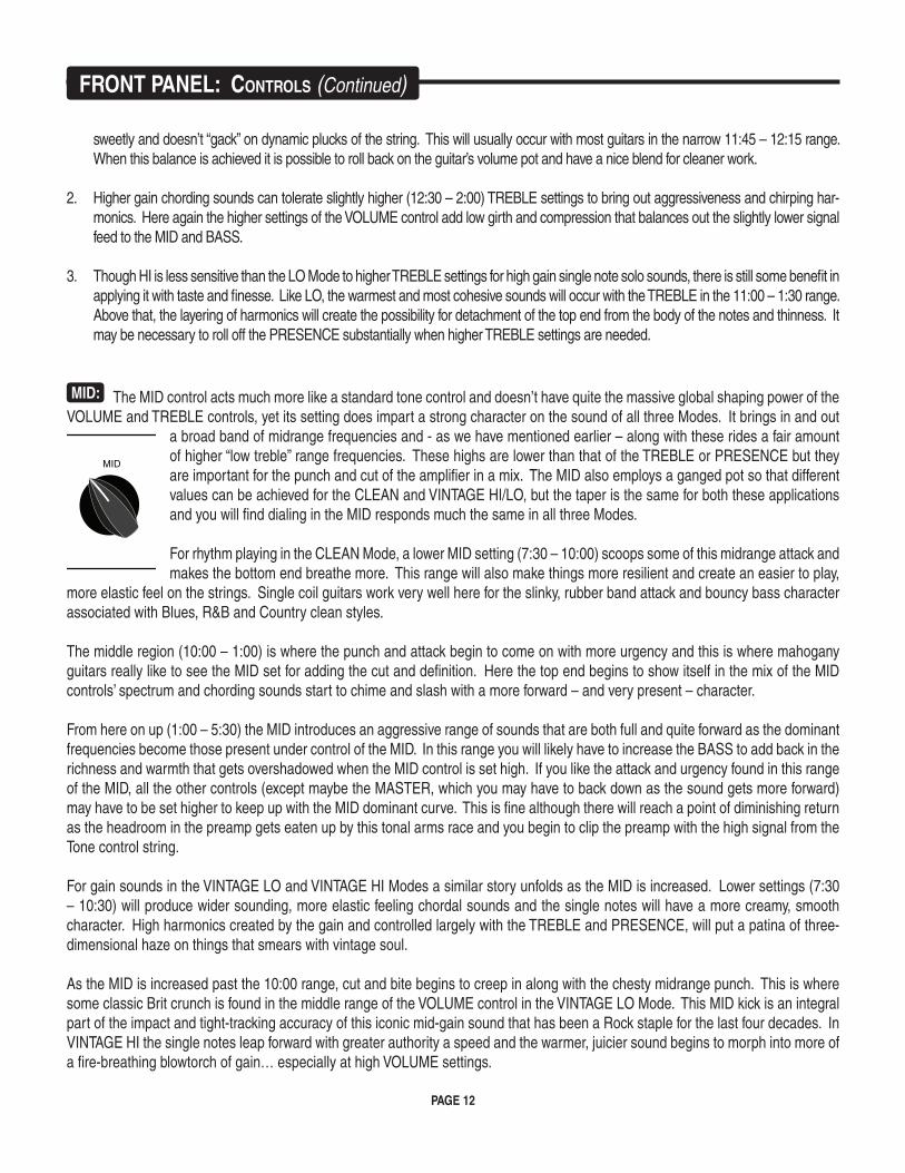
MID: The MID control acts much more like a standard tone control and doesn’t have quite the massive global shaping power of the VOLUME and TREBLE controls, yet its setting does impart a strong character on the sound of all three Modes. It brings in and out
a broad band of midrange frequencies and - as we have mentioned earlier – along with these rides a fair amount of higher “low treble” range frequencies. These highs are lower than that of the TREBLE or PRESENCE but they are important for the punch and cut of the amplifier in a mix. The MID also employs a ganged pot so that different values can be achieved for the CLEAN and VINTAGE HI/LO, but the taper is the same for both these applications and you will find dialing in the MID responds much the same in all three Modes.
For rhythm playing in the CLEAN Mode, a lower MID setting (7:30 – 10:00) scoops some of this midrange attack and makes the bottom end breathe more. This range will also make things more resilient and create an easier to play,
more elastic feel on the strings. Single coil guitars work very well here for the slinky, rubber band attack and bouncy bass character associated with Blues, R&B and Country clean styles.
The middle region (10:00 – 1:00) is where the punch and attack begin to come on with more urgency and this is where mahogany guitars really like to see the MID set for adding the cut and definition. Here the top end begins to show itself in the mix of the MID controls’ spectrum and chording sounds start to chime and slash with a more forward – and very present – character.
From here on up (1:00 – 5:30) the MID introduces an aggressive range of sounds that are both full and quite forward as the dominant frequencies become those present under control of the MID. In this range you will likely have to increase the BASS to add back in the richness and warmth that gets overshadowed when the MID control is set high. If you like the attack and urgency found in this range of the MID, all the other controls (except maybe the MASTER, which you may have to back down as the sound gets more forward) may have to be set higher to keep up with the MID dominant curve. This is fine although there will reach a point of diminishing return as the headroom in the preamp gets eaten up by this tonal arms race and you begin to clip the preamp with the high signal from the Tone control string.
For gain sounds in the VINTAGE LO and VINTAGE HI Modes a similar story unfolds as the MID is increased. Lower settings (7:30 – 10:30) will produce wider sounding, more elastic feeling chordal sounds and the single notes will have a more creamy, smooth character. High harmonics created by the gain and controlled largely with the TREBLE and PRESENCE, will put a patina of three-dimensional haze on things that smears with vintage soul.
As the MID is increased past the 10:00 range, cut and bite begins to creep in along with the chesty midrange punch. This is where some classic Brit crunch is found in the middle range of the VOLUME control in the VINTAGE LO Mode. This MID kick is an integral part of the impact and tight-tracking accuracy of this iconic mid-gain sound that has been a Rock staple for the last four decades. In VINTAGE HI the single notes leap forward with greater authority a speed and the warmer, juicier sound begins to morph into more of a fire-breathing blowtorch of gain… especially at high VOLUME settings.
INPUT FT. SW.
CLEAN
HI
LOW
FT. SW.
VOLUME TREBLE MID BASS PRESENCE MASTER
45W
90W
O
STANDBY
ON
Simul-Class 45 / 90
POWER
FrONT PANeL: CONTrOLS (Continued)
PAGE 13
Passing the 1:00 mark unleashes the brash attitude pent up in the MID frequencies and top end joins the party in a big way. Here is where you look for the most forward and aggressive attack over a wider range than that of TREBLE control. The feel on the strings will become less forgiving and your playing will be put under a microscope - mostly in the time domain. This region is great for push-ing Rock rhythm sounds to the forefront of a mix in VINTAGE LO, no matter how much gain you thicken it up with on the VOLUME control. Single note solo sounds in VINTAGE HI will be lightning fast and deadly accurate and certainly will be heard by all as they will have a definite point of origin.
One suggestion, or maybe more of a word of caution… the MID control contains frequencies that can be a little tough on the ears if not used with some discretion. Be sure to put your head down by the cabinet at some point and sample what you are dealing out to the audience and/or the microphone. You might be surprised how much impact – and possibly even pain – can be dialed in with higher settings of the MID. You may find the middle to lower range of the MID gives you plenty of attack and definition but still sounds balanced and warm and lets others enjoy your playing without wincing at every note.
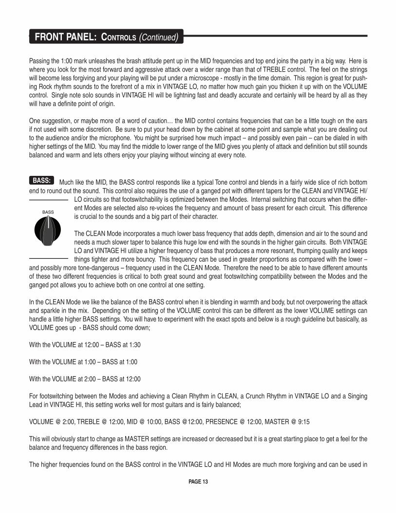
BASS: Much like the MID, the BASS control responds like a typical Tone control and blends in a fairly wide slice of rich bottom end to round out the sound. This control also requires the use of a ganged pot with different tapers for the CLEAN and VINTAGE HI/
LO circuits so that footswitchability is optimized between the Modes. Internal switching that occurs when the differ-ent Modes are selected also re-voices the frequency and amount of bass present for each circuit. This difference is crucial to the sounds and a big part of their character.
The CLEAN Mode incorporates a much lower bass frequency that adds depth, dimension and air to the sound and needs a much slower taper to balance this huge low end with the sounds in the higher gain circuits. Both VINTAGE LO and VINTAGE HI utilize a higher frequency of bass that produces a more resonant, thumping quality and keeps things tighter and more bouncy. This frequency can be used in greater proportions as compared with the lower –
and possibly more tone-dangerous – frequency used in the CLEAN Mode. Therefore the need to be able to have different amounts of these two different frequencies is critical to both great sound and great footswitching compatibility between the Modes and the ganged pot allows you to achieve both on one control at one setting.
In the CLEAN Mode we like the balance of the BASS control when it is blending in warmth and body, but not overpowering the attack and sparkle in the mix. Depending on the setting of the VOLUME control this can be different as the lower VOLUME settings can handle a little higher BASS settings. You will have to experiment with the exact spots and below is a rough guideline but basically, as VOLUME goes up - BASS should come down;
With the VOLUME at 12:00 – BASS at 1:30
With the VOLUME at 1:00 – BASS at 1:00
With the VOLUME at 2:00 – BASS at 12:00
For footswitching between the Modes and achieving a Clean Rhythm in CLEAN, a Crunch Rhythm in VINTAGE LO and a Singing Lead in VINTAGE HI, this setting works well for most guitars and is fairly balanced;
VOLUME @ 2:00, TREBLE @ 12:00, MID @ 10:00, BASS @12:00, PRESENCE @ 12:00, MASTER @ 9:15
This will obviously start to change as MASTER settings are increased or decreased but it is a great starting place to get a feel for the balance and frequency differences in the bass region.
The higher frequencies found on the BASS control in the VINTAGE LO and HI Modes are much more forgiving and can be used in
INPUT FT. SW.
CLEAN
HI
LOW
FT. SW.
VOLUME TREBLE MID BASS PRESENCE MASTER
45W
90W
O
STANDBY
ON
Simul-Class 45 / 90
POWER
FrONT PANeL: CONTrOLS (Continued)
PAGE 14
higher amounts than the lower frequencies present in CLEAN. BASS settings between 12:00 and 3:00 will be commonplace - with lower VOLUME settings needing higher BASS settings and higher VOLUME settings calling for a more careful use of the BASS. As the gain goes down (VOLUME 9:30 – 12:00) and things get tighter, there is a need for the rich low-end air that is created by the BASS control. When the gain saturates things as it’s cranked up (VOLUME 12:00 – 5:30) the notes thicken up and less bass is needed to create girth until - at a certain point - the bass frequencies start to slow things down and can even get in the way for some styles.
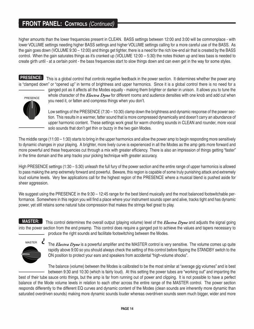
PRESENCE: This is a global control that controls negative feedback in the power section. It determines whether the power amp is “clamped down” or “opened up” in terms of brightness and upper harmonics. Since it is a global control there is no need for a
ganged pot as it affects all the Modes equally - making them brighter or darker in unison. It allows you to tune the whole character of the Electra Dyne for different rooms and audience densities with one knob and add cut when you need it, or fatten and compress things when you don’t.
Low settings of the PRESENCE (7:30 – 10:30) clamp down the brightness and dynamic response of the power sec-tion. This results in a warmer, fatter sound that is more compressed dynamically and doesn’t carry an abundance of upper harmonic content. These settings work great for warm chording sounds in CLEAN and rounder, more vocal solo sounds that don’t get thin or buzzy in the two gain Modes.
The middle range (11:00 – 1:30) starts to bring in the upper harmonics and allow the power amp to begin responding more sensitively to dynamic changes in your playing. A brighter, more lively curve is experienced in all the Modes as the amp gets more forward and more powerful and these frequencies cut through a mix with greater efficiency. There is also an impression of things getting “faster” in the time domain and the amp tracks your picking technique with greater accuracy.
High PRESENCE settings (1:30 – 5:30) unleash the full fury of the power section and the entire range of upper harmonics is allowed to pass making the amp extremely forward and powerful. Beware, this region is capable of some truly punishing attack and extremely loud volume levels. Very few applications call for the highest region of the PRESENCE where a musical blend is pushed aside for sheer aggression.
We suggest using the PRESENCE in the 9:30 – 12:45 range for the best blend musically and the most balanced footswitchable per-formance. Somewhere in this region you will find a place where your instrument sounds open and alive, tracks tight and has dynamic power, yet still retains some natural tube compression that makes the strings feel great to play.
MASTER: This control determines the overall output (playing volume) level of the Electra Dyne and adjusts the signal going into the power section from the end preamp. This control does require a ganged pot to achieve the values and tapers necessary to
produce the right sounds and facilitate footswitching between the Modes.
The Electra Dyne is a powerful amplifier and the MASTER control is very sensitive. The volume comes up quite rapidly above 9:00 so you should always check the setting of this control before flipping the STANDBY switch to the ON position to protect your ears and speakers from accidental “high-volume shocks”.
The balance (volume) between the Modes is calibrated to be the most similar at “average gig volumes” and is best between 9:30 and 10:30 (which is fairly loud). At this setting the power tubes are “working out” and imparting the
best of their tube sauce onto things, but the amp is far from running out of power and clipping. It is not possible to have a perfect balance of the Mode volume levels in relation to each other across the entire range of the MASTER control. The power section responds differently to the different EQ curves and dynamic content of the Modes (clean sounds are inherently more dynamic than saturated overdriven sounds) making more dynamic sounds louder whereas overdriven sounds seem much bigger, wider and more
FrONT PANeL: CONTrOLS (Continued)
INPUT FT. SW.
CLEAN
HI
LOW
FT. SW.
VOLUME TREBLE MID BASS PRESENCE MASTER
45W
90W
O
STANDBY
ON
Simul-Class 45 / 90
POWER
INPUT FT. SW.
CLEAN
HI
LOW
FT. SW.
VOLUME TREBLE MID BASS PRESENCE MASTER
45W
90W
O
STANDBY
ON
Simul-Class 45 / 90
POWER
PAGE 15
compressed. Internal steps are taken to even out this difference, but they can’t make up for the sensitivity difference in the power amp under all settings scenarios.
A CLEAN LEVEL “trim” pot is fitted on the Rear Panel (far left on Head Version – far right on Combo) that enables you to decrease the CLEAN Modes’ output level in relation to that of VINTAGE LO and HI.
This is not a “Master” in the true sense of the term, because it is wired in parallel with the Front Panel MASTER control and cannot increase the CLEAN Mode volume beyond that of the setting on the MASTER. However, the CLEAN LEVEL control is very effective at balancing the CLEAN with HI and LO, especially in low overall volume applications such as in music stores, small clubs or at home.
In these environments, the more dynamic nature of clean sounds comes across as louder than the more compressed overdrive sounds – which might sound bigger and wider – but don’t cut through and reach your ear as fast. If you find the CLEAN Mode is too loud at times - simply set the Front Panel MASTER to the desired playing level for HI and LO and “trim back” the CLEAN to the desired level with the Rear Panel CLEAN LEVEL.
NOTE: When the CLEAN LEVEL is set all the way clockwise - BYPASS (full up) - the control is effectively removed from the circuit and the amp operates as if it was not there at all.
NOTE: When the CLEAN LEVEL is set all the way counter-clockwise – TRIM (off) there will still be some signal passed if the Front Panel MASTER is set above 8:00.
NOTE: The Front Panel MASTER is always active even when you have decreased the CLEAN Mode volume with the CLEAN LEVEL. This can be handy if you have your Mode levels set with the two controls… to turn the whole amp up a little - just use the Front Panel MASTER and if the adjustment isn’t too extreme you shouldn’t have to touch the CLEAN LEVEL control.
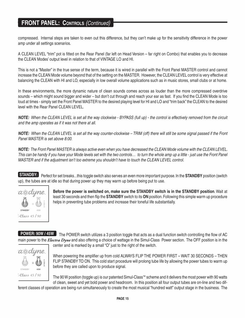
STANDBY: Perfect for set breaks...this toggle switch also serves an even more important purpose. In the STANDBY position (switch up), the tubes are at idle so that during power up they may warm up before being put to use.
Before the power is switched on, make sure the STANDBY switch is in the STANDBY position. Wait at least 30 seconds and then flip the STANDBY switch to its ON position. Following this simple warm up procedure helps in preventing tube problems and increase their toneful life substantially.
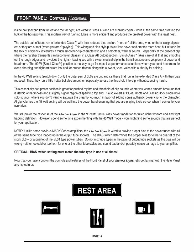
POWER: 90W / 45W The POWER switch utilizes a 3 position toggle that acts as a dual function switch controlling the flow of AC main power to the Electra Dyne and also offering a choice of wattage in the Simul-Class Power section. The OFF position is in the
center and is marked by a small “O” just to the right of the switch.
When powering the amplifier up from cold ALWAYS FLIP THE POWER FIRST – WAIT 30 SECONDS – THEN FLIP STANDBY TO ON. This cold start procedure will prolong tube life by allowing the power tubes to warm up before they are called upon to produce signal.
The 90 W position (toggle up) is our patented Simul-Class™ scheme and it delivers the most power with 90 watts of clean, sweet and yet bold power and headroom. In this position all four output tubes are on-line and two dif-
ferent classes of operation are being run simultaneously to create the most musical “hundred watt” output stage in the business. The
FrONT PANeL: CONTrOLS (Continued)
PAGE 16
inside pair (second from far left and the far right) are wired to Class AB and are running cooler - while at the same time creating the bulk of the horsepower. This modern way of running tubes is more efficient and produces the greatest power with the least heat.
The outside pair of tubes run in “extended Class A” with their reduced bias and are “more on” all the time, whether there is signal pres-ent or they are at rest (when you aren’t playing). This wiring and bias style puts out less power and creates more heat, but in trade for the lack of efficiency, it features a much smoother clip characteristic and a smoother, warmer sound… especially at the onset of clip where the harsher transients can become unpleasant in a Class AB output section. Simul-Class™ takes care of all that and smooths out the rough edges and re-voices the highs - leaving you with a sweet musical clip in the transition zone and yet plenty of power and headroom. The 90 W (Simul-Class™) position is the way to go for most live performance situations where you need headroom for clean chording and tight articulate low end for crunch rhythm along with a sweet, vocal voice with authority for soloing.
In the 45 Watt setting (switch down) only the outer pair of 6L6s are on, and it’s these that run in the extended Class A with their bias reduced. Thus, they run a little hotter but also smoother, especially across the threshold into clip without sounding harsh.
This essentially half-power position is great for pushed rhythm and threshold-of-clip sounds where you want a smooth break-up that is devoid of harshness and a slightly higher region of sparkling top end. It also excels at Blues, Roots and Classic Rock single note solo sounds, where you don’t want to saturate the preamp too much in favor of adding some authentic power clip to the character. At gig volumes the 45 watt setting will be well into the power band ensuring that you are playing it old school when it comes to your overdrive.
We still prefer the response of the Electra Dyne in the 90 watt Simul-Class power mode for its fuller, richer bottom end and tight tracking definition. However, spend some time experimenting with the 45 Watt mode – you might find some sounds that are perfect for your application.
NOTE: Unlike some previous MARK Series amplifiers, the Electra Dyne is wired to provide proper bias to the power tubes with all of the same tube type loaded up in the output tube sockets. The BIAS switch determines the proper bias for either a quartet of the stock 6L6 – or a quartet of the EL34 type power tubes. Do not mix tube types in the pairs of output tube sockets as the bias will be wrong - either too cold or too hot - for one or the other tube styles and sound bad and/or possibly cause damage to your amplifier.
CRITICAL: BIAS switch setting must match the tube type in use at all times!
Now that you have a grip on the controls and features of the Front Panel of your Electra Dyne, let’s get familiar with the Rear Panel and its features.
FrONT PANeL: CONTrOLS (Continued)
REST AREA
PAGE 17
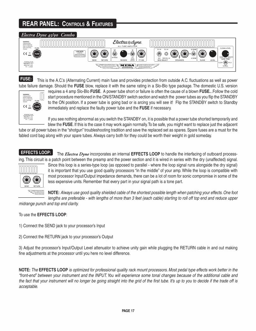
FUSE: This is the A.C.’s (Alternating Current) main fuse and provides protection from outside A.C. fluctuations as well as power tube failure damage. Should the FUSE blow, replace it with the same rating in a Slo-Blo type package. The domestic U.S. version
requires a 4 amp Slo-Blo FUSE. A power tube short or failure is often the cause of a blown FUSE...Follow the cold start procedure mentioned in the ON/STANDBY switch section and watch the power tubes as you flip the STANDBY to the ON position. If a power tube is going bad or is arcing you will see it! Flip the STANDBY switch to Standby immediately and replace the faulty power tube and the FUSE if necessary.
If you see nothing abnormal as you switch the STANDBY on, it is possible that a power tube shorted temporarily and blew the FUSE. If this is the case it may work again normally. To be safe, you might want to replace just the adjacent
tube or all power tubes in the “shotgun” troubleshooting tradition and save the replaced set as spares. Spare fuses are a must for the fabled cord bag along with your spare tubes. Always carry both for they could be worth their weight in gold someday.
EFFECTS LOOP: The Electra Dyne incorporates an internal EFFECTS LOOP to handle the interfacing of outboard process-ing. This circuit is a patch point between the preamp and the power section and it is wired in series with the dry (unaffected) signal.
Since this loop is a series-type loop (as opposed to parallel - where the loop signal runs alongside the dry signal) it is important that you use good quality processors “in the middle” of your amp. While the loop is compatible with most processor Input/Output impedance demands, there can be a lot of room for sonic compromise in some of the less expensive units. Remember that every part in your signal path is a tone part.
NOTE: Always use good quality shielded cable of the shortest possible length when patching your effects. One foot lengths are preferable - with lengths of more than 3 feet (each cable) starting to roll off top end and reduce upper
midrange punch and top end clarity.
To use the EFFECTS LOOP:
1) Connect the SEND jack to your processor’s Input
2) Connect the RETURN jack to your processor’s Output
3) Adjust the processor’s Input/Output Level attenuator to achieve unity gain while plugging the RETURN cable in and out making fine adjustments at the processor until you here no level difference.
NOTE: The EFFECTS LOOP is optimized for professional quality rack mount processors. Most pedal type effects work better in the “front-end” between your instrument and the INPUT. You will experience some tonal changes because of the additional cable and the fact that your instrument will no longer be going straight into the grid of the first tube. It’s up to you to decide if the trade off is acceptable.
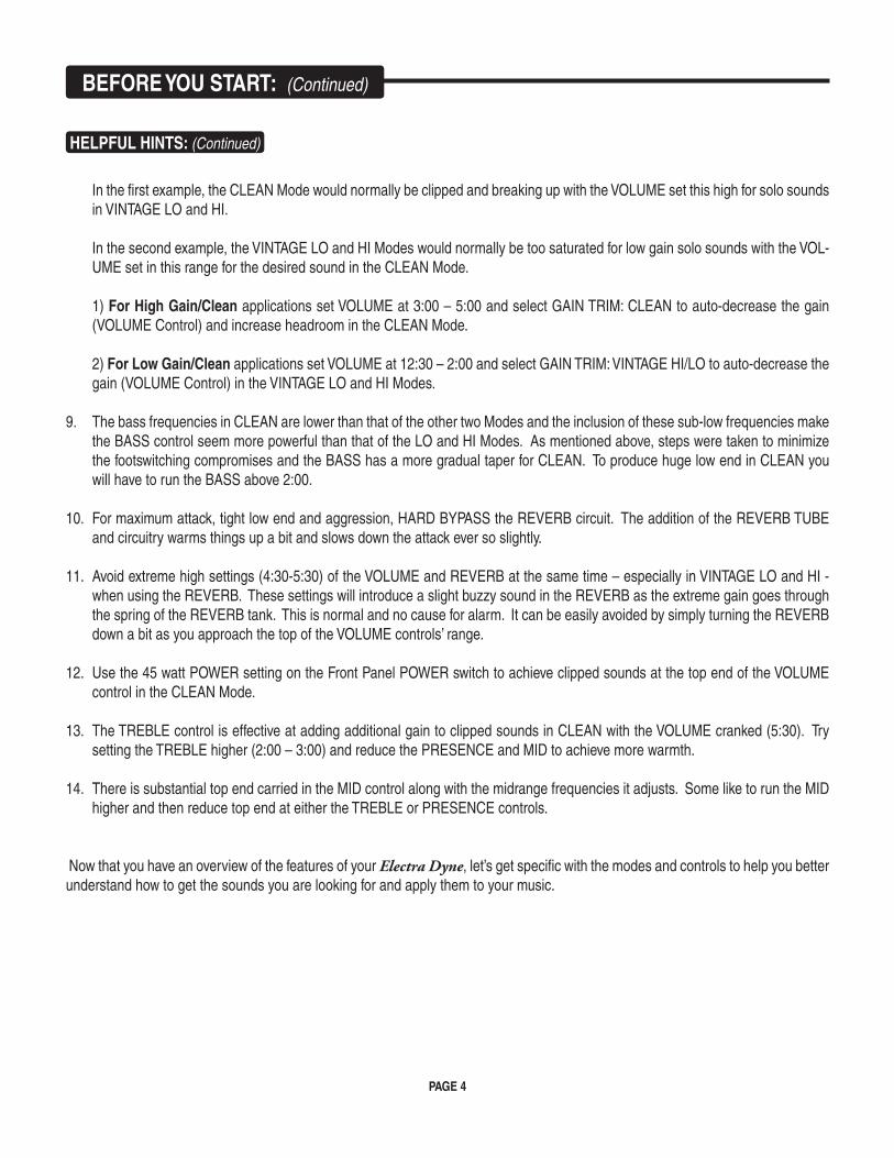
reAr PANeL: CONTrOLS & FeATUreS
Electra Dyne 45/90 Combo
FUSE
BYPASS
ON HI
LO
ON
MODEDEFEAT
6L6
EL-34 EL-34 8 OHM
4 OHMSEND RETURN REVERB FT. SW. BIAS SELECT SPEAKERS SLAVE LEVEL
RED=EL 34
LOOP NOTE:LOOP IS
HARD BYPASSEDWHEN NOT IN USE
100/120~50/60 Hz
4 A
4 ASLOBLO
ALL-TUBE AMPLIFIER
FUSE
GAIN TRIM
NORMAL
HI/LOCLEAN
CLEAN LEVEL
TRIM BYPASS
FUSE
BYPASS
ON HI
LO
ON
MODEDEFEAT
6L6
EL-34 EL-34 8 OHM
4 OHMSEND RETURN REVERB FT. SW. BIAS SELECT SPEAKERS SLAVE LEVEL
RED=EL 34
LOOP NOTE:LOOP IS
HARD BYPASSEDWHEN NOT IN USE
100/120~50/60 Hz
4 A
4 ASLOBLO
ALL-TUBE AMPLIFIER
FUSE
GAIN TRIM
NORMAL
HI/LOCLEAN
CLEAN LEVEL
TRIM BYPASS
FUSE
BYPASS
ON HI
LO
ON
MODEDEFEAT
6L6
EL-34 EL-34 8 OHM
4 OHMSEND RETURN REVERB FT. SW. BIAS SELECT SPEAKERS SLAVE LEVEL
RED=EL 34
LOOP NOTE:LOOP IS
HARD BYPASSEDWHEN NOT IN USE
100/120~50/60 Hz
4 A
4 ASLOBLO
ALL-TUBE AMPLIFIER
FUSE
GAIN TRIM
NORMAL
HI/LOCLEAN
CLEAN LEVEL
TRIM BYPASS
PAGE 18
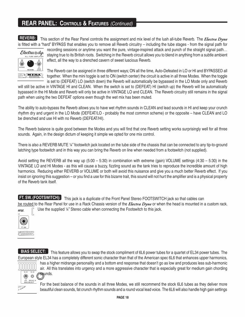
REVERB: This section of the Rear Panel controls the assignment and mix level of the lush all-tube Reverb. The Electra Dyne is fitted with a “hard” BYPASS that enables you to remove all Reverb circuitry – including the tube stages - from the signal path for
recording sessions or anytime you want the pure, vintage-inspired attack and punch of the straight signal path… staying true to its British roots. Switching in the Reverb circuit allows you to blend in anything from a subtle ambient effect, all the way to a drenched cavern of sweet luscious Reverb.
The Reverb can be assigned in three different ways; ON all the time, Auto-Defeated in LO or HI and BYPASSED all together. When the mini toggle is set to ON (switch center) the circuit is active in all three Modes. When the toggle is set to (DEFEAT) LO (switch down) the Reverb will automatically be bypassed in the LO Mode only and Reverb
will still be active in VINTAGE HI and CLEAN. When the switch is set to (DEFEAT) HI (switch up) the Reverb will be automatically bypassed in the HI Mode and Reverb will only be active in VINTAGE LO and CLEAN. The Reverb circuitry still remains in the signal path when using the two DEFEAT options even though the wet mix has been muted.
The ability to auto-bypass the Reverb allows you to have wet rhythm sounds in CLEAN and lead sounds in HI and keep your crunch rhythm dry and urgent in the LO Mode (DEFEAT/LO - probably the most common scheme) or the opposite – have CLEAN and LO be drenched and use HI with no Reverb (DEFEAT/HI).
The Reverb balance is quite good between the Modes and you will find that one Reverb setting works surprisingly well for all three sounds. Again, in the design dictum of keeping it simple we opted for one mix control.
There is also a REVERB MUTE ¼” footswitch jack located on the tube side of the chassis that can be connected to any tip-to-ground latching type footswitch and in this way you can bring the Reverb on line when needed from a footswitch (not supplied).
Avoid setting the REVERB all the way up (5:00 – 5:30) in combination with extreme (gain) VOLUME settings (4:30 – 5:30) in the VINTAGE LO and HI Modes - as this will cause a buzzy, fizzling sound as the tank tries to reproduce the incredible amount of high harmonics. Reducing either REVERB or VOLUME or both will avoid this nuisance and give you a much better Reverb effect. If you insist on ignoring this suggestion – or you find a use for this bizarre trait, this sound will not hurt the amplifier and is a physical property of the Reverb tank itself.
FT. SW. (FOOTSWITCH): This jack is a duplicate of the Front Panel Stereo FOOTSWITCH jack so that cables can be routed to the Rear Panel for use in a Rack Chassis version of the Electra Dyne or when the head is mounted in a custom rack.
Use the supplied ¼” Stereo cable when connecting the Footswitch to this jack.
BIAS SELECT: This feature allows you to swap the stock compliment of 6L6 power tubes for a quartet of EL34 power tubes. The European style EL34 has a completely different sonic character than that of the American spec 6L6 that enhances upper harmonics,
has a higher midrange personality and a bottom end response that doesn’t go as low and produces less sub-harmonic air. All this translates into urgency and a more aggressive character that is especially great for medium gain chording sounds.
For the best balance of the sounds in all three Modes, we still recommend the stock 6L6 tubes as they deliver more beautiful clean sounds, fat crunch rhythm sounds and a round vocal lead voice. The 6L6 will also handle high gain settings
reAr PANeL: CONTrOLS & FeATUreS (Continued)
FUSE
BYPASS
ON HI
LO
ON
MODEDEFEAT
6L6
EL-34 EL-34 8 OHM
4 OHMSEND RETURN REVERB FT. SW. BIAS SELECT SPEAKERS SLAVE LEVEL
RED=EL 34
LOOP NOTE:LOOP IS
HARD BYPASSEDWHEN NOT IN USE
100/120~50/60 Hz
4 A
4 ASLOBLO
ALL-TUBE AMPLIFIER
FUSE
GAIN TRIM
NORMAL
HI/LOCLEAN
CLEAN LEVEL
TRIM BYPASS
FUSE
BYPASS
ON HI
LO
ON
MODEDEFEAT
6L6
EL-34 EL-34 8 OHM
4 OHMSEND RETURN REVERB FT. SW. BIAS SELECT SPEAKERS SLAVE LEVEL
RED=EL 34
LOOP NOTE:LOOP IS
HARD BYPASSEDWHEN NOT IN USE
100/120~50/60 Hz
4 A
4 ASLOBLO
ALL-TUBE AMPLIFIER
FUSE
GAIN TRIM
NORMAL
HI/LOCLEAN
CLEAN LEVEL
TRIM BYPASS
FUSE
BYPASS
ON HI
LO
ON
MODEDEFEAT
6L6
EL-34 EL-34 8 OHM
4 OHMSEND RETURN REVERB FT. SW. BIAS SELECT SPEAKERS SLAVE LEVEL
RED=EL 34
LOOP NOTE:LOOP IS
HARD BYPASSEDWHEN NOT IN USE
100/120~50/60 Hz
4 A
4 ASLOBLO
ALL-TUBE AMPLIFIER
FUSE
GAIN TRIM
NORMAL
HI/LOCLEAN
CLEAN LEVEL
TRIM BYPASS
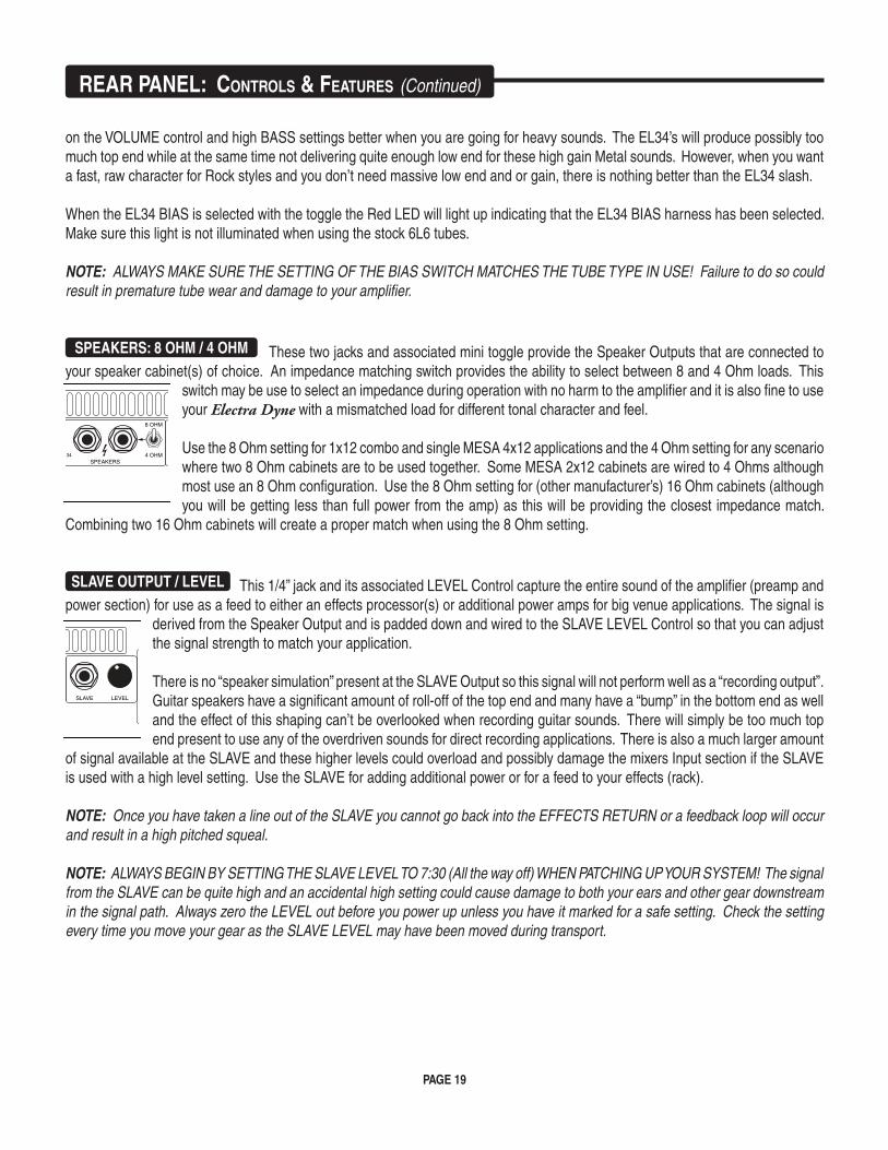
PAGE 19
reAr PANeL: CONTrOLS & FeATUreS (Continued)
on the VOLUME control and high BASS settings better when you are going for heavy sounds. The EL34’s will produce possibly too much top end while at the same time not delivering quite enough low end for these high gain Metal sounds. However, when you want a fast, raw character for Rock styles and you don’t need massive low end and or gain, there is nothing better than the EL34 slash.
When the EL34 BIAS is selected with the toggle the Red LED will light up indicating that the EL34 BIAS harness has been selected. Make sure this light is not illuminated when using the stock 6L6 tubes.
NOTE: ALWAYS MAKE SURE THE SETTING OF THE BIAS SWITCH MATCHES THE TUBE TYPE IN USE! Failure to do so could result in premature tube wear and damage to your amplifier.
SPEAKERS: 8 OHM / 4 OHM These two jacks and associated mini toggle provide the Speaker Outputs that are connected to your speaker cabinet(s) of choice. An impedance matching switch provides the ability to select between 8 and 4 Ohm loads. This
switch may be use to select an impedance during operation with no harm to the amplifier and it is also fine to use your Electra Dyne with a mismatched load for different tonal character and feel.
Use the 8 Ohm setting for 1x12 combo and single MESA 4x12 applications and the 4 Ohm setting for any scenario where two 8 Ohm cabinets are to be used together. Some MESA 2x12 cabinets are wired to 4 Ohms although most use an 8 Ohm configuration. Use the 8 Ohm setting for (other manufacturer’s) 16 Ohm cabinets (although you will be getting less than full power from the amp) as this will be providing the closest impedance match.
Combining two 16 Ohm cabinets will create a proper match when using the 8 Ohm setting.
SLAVE OUTPUT / LEVEL This 1/4” jack and its associated LEVEL Control capture the entire sound of the amplifier (preamp and power section) for use as a feed to either an effects processor(s) or additional power amps for big venue applications. The signal is
derived from the Speaker Output and is padded down and wired to the SLAVE LEVEL Control so that you can adjust the signal strength to match your application.
There is no “speaker simulation” present at the SLAVE Output so this signal will not perform well as a “recording output”. Guitar speakers have a significant amount of roll-off of the top end and many have a “bump” in the bottom end as well and the effect of this shaping can’t be overlooked when recording guitar sounds. There will simply be too much top end present to use any of the overdriven sounds for direct recording applications. There is also a much larger amount
of signal available at the SLAVE and these higher levels could overload and possibly damage the mixers Input section if the SLAVE is used with a high level setting. Use the SLAVE for adding additional power or for a feed to your effects (rack).
NOTE: Once you have taken a line out of the SLAVE you cannot go back into the EFFECTS RETURN or a feedback loop will occur and result in a high pitched squeal.
NOTE: ALWAYS BEGIN BY SETTING THE SLAVE LEVEL TO 7:30 (All the way off) WHEN PATCHING UP YOUR SYSTEM! The signal from the SLAVE can be quite high and an accidental high setting could cause damage to both your ears and other gear downstream in the signal path. Always zero the LEVEL out before you power up unless you have it marked for a safe setting. Check the setting every time you move your gear as the SLAVE LEVEL may have been moved during transport.
FUSE
BYPASS
ON HI
LO
ON
MODEDEFEAT
6L6
EL-34 EL-34 8 OHM
4 OHMSEND RETURN REVERB FT. SW. BIAS SELECT SPEAKERS SLAVE LEVEL
RED=EL 34
LOOP NOTE:LOOP IS
HARD BYPASSEDWHEN NOT IN USE
100/120~50/60 Hz
4 A
4 ASLOBLO
ALL-TUBE AMPLIFIER
FUSE
GAIN TRIM
NORMAL
HI/LOCLEAN
CLEAN LEVEL
TRIM BYPASS
FUSE
BYPASS
ON HI
LO
ON
MODEDEFEAT
6L6
EL-34 EL-34 8 OHM
4 OHMSEND RETURN REVERB FT. SW. BIAS SELECT SPEAKERS SLAVE LEVEL
RED=EL 34
LOOP NOTE:LOOP IS
HARD BYPASSEDWHEN NOT IN USE
100/120~50/60 Hz
4 A
4 ASLOBLO
ALL-TUBE AMPLIFIER
FUSE
GAIN TRIM
NORMAL
HI/LOCLEAN
CLEAN LEVEL
TRIM BYPASS
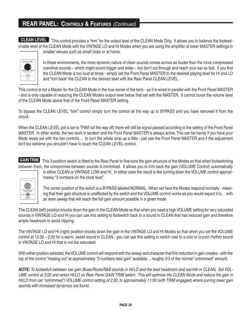
PAGE 20
CLEAN LEVEL This control provides a “trim” for the output level of the CLEAN Mode Only. It allows you to balance the footswit-chable level of the CLEAN Mode with the VINTAGE LO and HI Modes when you are using the amplifier at lower MASTER settings in
smaller venues such as small clubs or at home.
In these environments, the more dynamic nature of clean sounds comes across as louder than the more compressed overdrive sounds – which might sound bigger and wider – but don’t cut through and reach your ear as fast. If you find the CLEAN Mode is too loud at times - simply set the Front Panel MASTER to the desired playing level for HI and LO and “trim back” the CLEAN to the desired level with the Rear Panel CLEAN LEVEL.
This control is not a Master for the CLEAN Mode in the true sense of the term - as it is wired in parallel with the Front Panel MASTER - and is only capable of reducing the CLEAN Mode’s output level below that set with the MASTER. It cannot boost the volume level of the CLEAN Mode above that of the Front Panel MASTER setting.
To bypass the CLEAN LEVEL “trim” control simply turn the control all the way up to BYPASS and you have removed it from the circuit.
When the CLEAN LEVEL pot is set to TRIM (all the way off) there will still be signal passed according to the setting of the Front Panel MASTER. In other words, the two work in tandem and the Front Panel MASTER is always active. This can be handy if you have your Mode levels set with the two controls… to turn the whole amp up a little - just use the Front Panel MASTER and if the adjustment isn’t too extreme you shouldn’t have to touch the CLEAN LEVEL control.
GAIN TRIM This 3-position switch is fitted to the Rear Panel to fine-tune the gain structure of the Modes so that when footswitching between them, the compromise between sounds is minimized. It allows you to trim back the gain (VOLUME Control) automatically
in either CLEAN or VINTAGE LOW and HI. In either case the result is like turning down the VOLUME control approxi-mately “3 numbers on the clock face”.
The center position of the switch is a BYPASS labeled NORMAL. When set here the Modes respond normally - mean-ing that their gain structure is unaffected by the switch and the VOLUME control works as you would expect it to… with an even sweep that will reach the full gain amount possible in a given mode.
The CLEAN (left) position knocks down the gain in the CLEAN Mode so that when you need a high VOLUME setting for very saturated sounds in VINTAGE LO and HI you can use this setting to footswitch back to a sound in CLEAN that has reduced gain and therefore ample headroom to avoid clipping.
The VINTAGE LO and HI (right) position knocks down the gain in the VINTAGE LO and HI Modes so that when you set the VOLUME control at 12:30 – 2:00 for a warm, sweet sound in CLEAN - you can use this setting to switch over to a solo or crunch rhythm sound in VINTAGE LO and HI that is not too saturated.
With either position selected, the VOLUME control will respond with the sweep and character that this reduction in gain creates - with the top of the control “maxing out” at approximately “3 numbers less gain” available… roughly 2/3 of the normal “untrimmed” amount. NOTE: To footswitch between low gain Blues/Roots/R&B sounds in HI/LO and the best headroom and warmth in CLEAN; Set VOL-UME control at 2:00 and select HI/LO on Rear Panel GAIN TRIM switch. This will optimize the CLEAN Mode and reduce the gain in HI/LO from (an “untrimmed”) VOLUME control setting of 2:00, to approximately 11:00 (with TRIM engaged) where purring lower gain sounds with increased dynamics are found.
reAr PANeL: CONTrOLS & FeATUreS (Continued)
PAGE 21
NOTE: To footswitch between high gain Rock/Metal/Heavy sounds in HI/LO and rhythm sounds with enough headroom to avoid clip-ping in CLEAN; Set VOLUME at 3:00 – 5:00 and select CLEAN on Rear Panel GAIN TRIM switch. This will optimize the HI/LO Modes and reduce the gain in CLEAN from (an “untrimmed”) VOLUME control setting, to approximately 11:00 (with TRIM engaged) so that the CLEAN mode will not be clipped and bloated.
Now that we’ve covered the features and operation of your Electra Dyne it’s time to enjoy the best part…the sound and feel! We wish you many years of inspiration, fulfillment and musical satisfaction from your new Electra Dyne.
reAr PANeL: CONTrOLS & FeATUreS (Continued)
PAGE 22
TUBE NOISE & MICROPHONICS: You may occasionally experience some form of tube noise or microphonics. Certainly no cause for alarm, this quirky behavior comes with the territory and the Tone. Much like changing a light bulb, you don’t need a technician to cure these types of minor user serviceable annoyances and in fact, you’ll be amazed at how easy it is to cure tube problems...by simply swapping out a pre-amp or power tube!
First may we suggest that you set the amplifier up on something so that you can get to the tubes comfortably without having to bend down. It also helps to have adequate lighting as you will need to see the tube sockets clearly to swap tubes. Use caution and com-mon sense when touching the tubes after the amplifier has been on as they may be extremely hot! If they are hot and you don’t want to wait for them to cool off, try grasping them with a rag and also note that the glass down around the bulbous silvery tip is considerably less hot which makes it easier to handle. Gently rock the tube back and forth as you pull it away from its socket.
DIAGNOSING POWER TUBE FAILURE: There are two main types of tube faults: shorts and noise. Both large and small tubes may fall prey to either of these problems but diagnosis and remedy is usually simple.
If a fuse blows, the problem is most likely a shorted power tube and shorts can either be mild or severe. In a mildly shorted tube the electron flow has overcome the control grid and excess current flows to the plate. You will usually hear the amp become distorted and begin to hum slightly. If this occurs, quickly look at the power tubes as you switch the amp to STANDBY and try to identify one as glowing red hot. It is likely that two of a pair will be glowing since the “shorted” tube will pull down the bias for its adjacent mates, but one tube may be glowing hotter — and that one is the culprit. The other two are often fine — unless they’ve been glowing bright red for several minutes.
Because there is no physical short inside the tube (just electrons rioting out of control) merely switching to STANDBY for a few mo-ments then back to ON will usually cure the problem...at least temporarily. Watch the tubes carefully now. Should the problem recur, the intermittent tube will visibly start to over heat before the others and thus it can be identified. It should be replaced with one from the same color batch, shown on its label. Call us and we will send one out to you.
The severe short is not nearly so benign. In the worst cases, a major arcing short occurs between the plate and the cathode with visible lightning inside the glass and a major noise through the speaker. If this is seen to happen, IMMEDIATELY turn the amp to STANDBY. By this time the fuse probably will have blown. Such a short is usually caused by a physical breakdown inside the tube including contaminate coming loose or physical contact (or near contact) between the elements. Replace it and the fuse with the proper slo-blo type and power up the amp using the power up procedure as we described earlier in this manual.
TUBE NOISE: Often caused by contamination within in a tube, the culprit can usually be identified, and by lightly tapping on the glass, you will probably hear the noise change. Hearing some noise through the speakers while tapping on the 12AX7’s is normal however. And the one nearer the INPUT will always sound louder because its output is being further amplified by the second 12AX7.
The power tubes should be all but quiet when they are tapped. If crackling or hissing changes with the tapping, you have probably found the problem. To confirm a noisy power tube, merely put the amplifier on Standby, remove it from its socket and turn it back on. It will cause no damage to run the amplifier briefly with one power tube missing. You may notice a slight background hum, however, as the push-pull becomes unbalanced. Whenever you are trying to diagnose a suspect tube, keep your other hand on the POWER and STANDBY switches ready to shut them off instantly in the unlikely case you provoke a major short.
If you think you’ve located a problem tube but aren’t sure, we recommend substituting the suspect with a new one just to be sure of your diagnoses. You will be doing yourself and us a big favor by just following the simple guidelines previously mentioned regarding tube replacement. You’ll probably be successful with much less effort than is required to disconnect everything and haul the unit to a technician who will basically perform the same simple tests. If the tubes are still within their six-month warranty period, we will happily send you a replacement. Just note the color designation on the tube label so that we can send you the appropriate match.
PAGE 23
DIAGNOSING PRE-AMP TUBE PROBLEMS: Because your amplifier is an all tube design, it is quite possible that you will at some point experience minor pre-amp tube noise. Rest assured - this is no cause for alarm and you can take care of the problem yourself in a matter of minutes by simply swapping tubes.
Let us begin by saying; It is a “very good” idea to keep at least a couple of spare pre-amp tubes on hand at all times to insure unin-terrupted performance. These minor pre-amp tube problems can take many forms but can generally be described in two categories: Noise and Microphonics. Noise can be in the form of crackling, sputtering, white noise/hiss and/or hum. Microphonic problems usually appear in the form of a ringing or high pitched squealing that gets worse as the gain or volume is increased thus are more noticeable in the higher gain “HI” modes. Microphonic problems are easily identified because the problem is still present even with the instru-ments’ volume off or unplugged altogether - unlike pick-up feedback which ceases as the instrument is turned down. Microphonic noise is caused by mechanical vibration and shock: think of banging a microphone around and you’ll understand where the word came from.
The best way to approach a pre-amp tube problem is to see if it occurs only in one specific mode or channel. This should lead you to the tube needing replacement. Then all that remains is to swap the suspect tube for a known good performer. If you cannot narrow down the trouble to a specific mode or channel, the problem may be the small tube that drives the power tubes which is operational in all modes and channels. Though rare, a problem with the driver tube would show up in all aspects of performance - so if you can’t narrow the problem down to being mode or channel specific, you may want to try replacing the driver tube. Driver problems generally show themselves in the form of crackling or hum in all modes of performance and/or weak overall output from the amplifier. Occasion-ally an anemic driver tube will cause the amplifier to sound flat and lifeless, but this is somewhat uncommon, as worn power tubes are a more likely suspect for this type of problem.
Sometimes making the diagnosis is more trouble than it’s worth and it’s faster and easier to merely replace the small pre-amp tubes ONE AT A TIME with a replacement known to be good. But MAKE SURE you keep returning the tubes to their original socket until you hit the one that cures the problem. You’ll notice that tubes located nearer to the INPUT jack always sound noisier...but this is because they are at the start of the chain and their noise gets amplified over and over by the tubes that follow. The tube that goes into this “input socket” (usually labeled V1) needs to be the least noisy of the bunch. The tube that goes at the end of the preamp chain - just ahead of the power tubes - can be quite noisy without causing any problem at all. The tubes in your amp have already been located in the most appropriate sockets and this is why you should NEVER pull them all out at once and ALWAYS swap them one at a time. ALWAYS return a perfectly good tube to its original socket. Also it’s a good idea to put the amp on STANDBY when swapping tubes to reduce the heat build up in the tubes themselves and to prevent explosive noises (which can still occur even if you are pulling the tubes away from their sockets gently) from coming through the speaker.
Remember, take your time, be patient and chances are real good that you can fix your amp yourself by finding and replacing the bad tube. It kills us to see someone who has shipped their amp back to us...and all it needed was a simple tube replacement! If you must send back your amp, remove the chassis from the cabinet by unscrewing the four mounting bolts on the bottom top. The chassis then slides back like a drawer and comes out from the back. Remove the big power tubes and mark them according to their location from left to right 1, 2 etc. They need to be wrapped separately with plenty of wadded up newspaper around them and put in a smaller box within the larger carton. Remove the Rectifier tubes and wrap them also. You can leave the preamp tubes in or remove them and wrap them separately being sure to label their location. (See Tube Task Chart.)
To wrap the chassis, use plenty of tightly wadded up newspaper so there is at least six inches of “crush space” between the chassis and the cardboard box. Bubble wrap also works well, but please DON’T use styrene peanuts - they will shift during transit and get lodged inside your electronics as well as allowing your amp to end up at the bottom of the box unprotected and possibly damaged.
Pre-amp tubes don’t normally wear out as a rule. Therefore, it is not a good idea to change them just for the sake of changing them. If there isn’t a problem - don’t fix it. If there is no result from your substitutions, it may be possible that you have more than one problematic tube. Though rare, this does happen and though it makes the troubleshooting process a little more intimidating, it is still possible to cure the problem yourself.
NOTE: It is normal to hear a slight metallic ringing sound when tapping on the preamp tubes. As long as the tube does not break into oscillation or start crackling or any other form of bizarre noise, it is considered normal and functional.
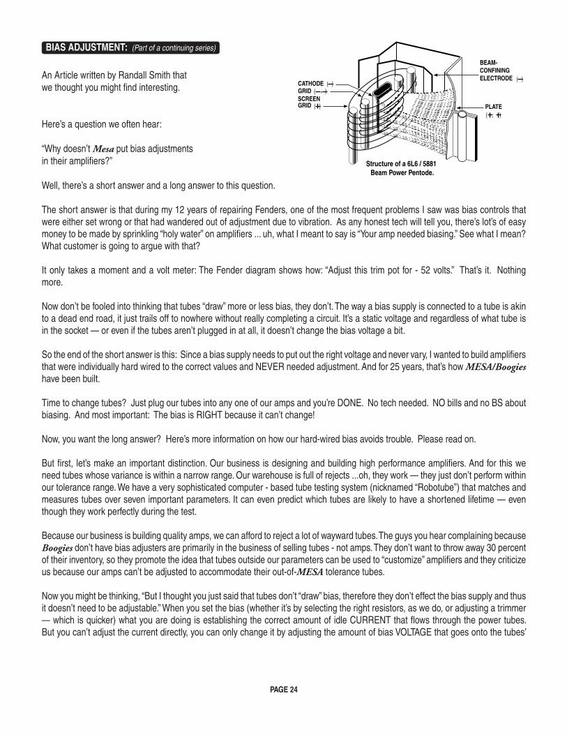
PAGE 24
BIAS ADJUSTMENT: (Part of a continuing series)
An Article written by Randall Smith thatwe thought you might find interesting.
Here’s a question we often hear:
“Why doesn’t Mesa put bias adjustments in their amplifiers?”
Well, there’s a short answer and a long answer to this question.
The short answer is that during my 12 years of repairing Fenders, one of the most frequent problems I saw was bias controls that were either set wrong or that had wandered out of adjustment due to vibration. As any honest tech will tell you, there’s lot’s of easy money to be made by sprinkling “holy water” on amplifiers ... uh, what I meant to say is “Your amp needed biasing.” See what I mean? What customer is going to argue with that?
It only takes a moment and a volt meter: The Fender diagram shows how: “Adjust this trim pot for - 52 volts.” That’s it. Nothing more.
Now don’t be fooled into thinking that tubes “draw” more or less bias, they don’t. The way a bias supply is connected to a tube is akin to a dead end road, it just trails off to nowhere without really completing a circuit. It’s a static voltage and regardless of what tube is in the socket — or even if the tubes aren’t plugged in at all, it doesn’t change the bias voltage a bit.
So the end of the short answer is this: Since a bias supply needs to put out the right voltage and never vary, I wanted to build amplifiers that were individually hard wired to the correct values and NEVER needed adjustment. And for 25 years, that’s how MESA/Boogies have been built.
Time to change tubes? Just plug our tubes into any one of our amps and you’re DONE. No tech needed. NO bills and no BS about biasing. And most important: The bias is RIGHT because it can’t change!
Now, you want the long answer? Here’s more information on how our hard-wired bias avoids trouble. Please read on.
But first, let’s make an important distinction. Our business is designing and building high performance amplifiers. And for this we need tubes whose variance is within a narrow range. Our warehouse is full of rejects ...oh, they work — they just don’t perform within our tolerance range. We have a very sophisticated computer - based tube testing system (nicknamed “Robotube”) that matches and measures tubes over seven important parameters. It can even predict which tubes are likely to have a shortened lifetime — even though they work perfectly during the test.
Because our business is building quality amps, we can afford to reject a lot of wayward tubes. The guys you hear complaining because Boogies don’t have bias adjusters are primarily in the business of selling tubes - not amps. They don’t want to throw away 30 percent of their inventory, so they promote the idea that tubes outside our parameters can be used to “customize” amplifiers and they criticize us because our amps can’t be adjusted to accommodate their out-of-MESA tolerance tubes.
Now you might be thinking, “But I thought you just said that tubes don’t “draw” bias, therefore they don’t effect the bias supply and thus it doesn’t need to be adjustable.” When you set the bias (whether it’s by selecting the right resistors, as we do, or adjusting a trimmer — which is quicker) what you are doing is establishing the correct amount of idle CURRENT that flows through the power tubes. But you can’t adjust the current directly, you can only change it by adjusting the amount of bias VOLTAGE that goes onto the tubes’
..
.
.
............
....
...
....
.......
..........
( )
( ) ( ) ,
( , )
( )
PLATE
Structure of a 6L6 / 5881 Beam Power Pentode.
BEAM-CONFININGELECTRODE
SCREENGRID
GRIDCATHODE
PAGE 25
BIAS ADJUSTMENT: (Continued) control grids. Voltage and current are NOT the same. Current is the AMOUNT of electricity, the “quantity” — and is measured in amperes. Voltage is the degree of electric charge — like the “pressure” to use the old water analogy. Let me illustrate how different voltage and current are:
When you scrape your feet across a carpeted floor in dry, wintery conditions, your body can become charged with 50,000 to 100,000 volts of static electricity. And when you reach for the door knob, a spark jumps and you feel it! The voltage is super high but the cur-rent (measured in micro-amps) is tiny - otherwise you would die from electrocution.
Contrast this with your car battery, which puts out a mere 12 volts. You can lay your hands right across the terminals and not feel a thing. Yet the amount of current available can run to several hundred amperes .. enough to turn over a cold engine and get it started.
So current and voltage are two totally separate electrical parameters — though when you multiply them together, you get POWER, which is measured in watts.
When you set the bias of an amplifier, you are adjusting the static VOLTAGE at the control grid of the tube in order to produce a desired amount of idle CURRENT flowing to the tube’s plate. A small change in grid voltage, produces a large change in the amount of current flowing — and that’s basically how a tube works. Say that again because it’s super important: A small change in voltage at the grid causes a large change in current flowing to the plate. See, that’s the essence of amplification: A small change causing a large change. And here it’s a small voltage change causing a large current change. The bias conditions are what determines how much current flows through the big power tubes when you’re not playing. And what drives your speakers is fluctuations in that current flow when you ARE playing. If the amount of current increases and decreases 440 times per second, then you’ll hear an A note. If the fluctuations in current flow are large and still at 440 per second, you’ll hear an A that is LOUD!
But for purposes of biasing, it’s the amount of “plate current” flowing with no signal applied that’s important. Unfortunately current is hard to measure because the circuit must be interrupted — as in “cut the wire” — and the meter spliced “in series” with the broken circuit. But measuring VOLTAGE is easy. It is not necessary to interrupt the circuit because a voltage reading can be taken in PAR-ALLEL with the circuit intact.
Thus, as a matter of convenience, most bias settings are given in volts at the grid ... even though current through the plate is the important factor. In fact plate current is so inconvenient (and dangerous) to measure that Fender doesn’t even state what the correct value should be. They only give the grid voltage that will produce that current. (That’s the minus 52.) But that only happens if the tubes being used are “in spec.”
As long as the tubes ARE “in spec”, the right bias voltage will always give the correct plate “CURRENT” — but then there’s no need for the bias voltage to be adjustable!
If the tubes are NOT in spec, then the only proper way to re-set the bias is to cut the circuit and measure the current while adjusting the bias ... but no manufacturer I know even STATES the desired current value! Be that as it may, when the original bias voltage is altered far enough, it will compensate for the tube’s abnormal performance and the correct amount of idle current flow may then be restored. Clearly this is something most repair techs should not attempt.
Some newer amps have LED indicators connected to the circuit which will turn on when the right threshold of current flow has been reached. This is an improvement, and almost worthy if you’re willing to accept resistors and lights added into your amplifier’s audio path — which we aren’t.
The other “advantage” of this system is that it allows some amp manufacturers to avoid matching their power tubes. The thinking is that adjusting the bias to each tube separately eradicates the inherent differences between the tubes by insuring that the same current flows through each one.
PAGE 26
BIAS ADJUSTMENT: (Continued) Again, this has some merit .. but it’s still not as good as using tubes that are matched in the first place because compensating for the mismatch causes the push-pull circuit itself to become unbalanced. Two wrongs don’t really make a right.
Some of the other recommended biasing, “methods” — such as -”.. tubes running red hot, increase the bias .. sounds harsh and runs too cool, turn it down ...” are guesswork at best. Luckily, one of the great things about tube amps is that they can usually stand some abuse without causing any real harm ... at least not immediately. But don’t these alterations imply that you are second-guessing the amp designer and that there’s a better set of operating conditions that the designer missed but the tube sellers have discovered?
Now some players may like the sound of their amp altered by tubes with extreme characteristics and with the bias set to help compen-sate. But often it is the mere novelty of change that they’re really responding to and when the amp goes back to the proper original way, we’ve seen them be far happier still!
Because every part in every one of our designs has been meticulously evaluated, compared and stressed over — no matter how seemingly insignificant it might be. And with every design we look for a “sweet spot” where all the parameters — including the bias — come together to give the best sonic performance, consistently and reliably. Every part and voltage is important — yet no one complains that these other parameters aren’t available for tinkering.
Consider our patented Simul-Class circuitry where there are two different bias voltages used for separate pairs of power tubes ... and changing one voltage also changes the other. Great care goes into getting this just right and we think we’d be asking for trouble to have it adjustable for the world to play with ... unless you like paying to have your amp messed up. Sorry, I meant to say, “Uh, ... your amp needed biasing.” If that doesn’t appeal to you, then merely plug a matched set of MESA tubes into one of our amps and you’re ready for tone. Guar-anteed. You’d be amazed at the number of service calls we field every day that lead to a diagnosis of out-of-tolerance, non-spec tube problems. To think these would be prevented by including a bias adjustment is something of an insult to you and us. If you put the wrong size tires on your car, do you think changing the pressure will make them right?
Please, don’t think this is a blanket indictment of the other guys selling tubes — it isn’t. And their tubes aren’t all bad either. It just doesn’t make sense to pay more of your hard earned cash for tubes that were probably made in the same Russian or Chinese fac-tory and which have the possibility of being outside the performance window we select for your amp. And it pains us to hear the hype and mystique built up around biasing when twenty-five years of evidence affirms our decision to make bias circuits that “never need adjustment”. How much money and trouble that has saved MESA/Boogie players you couldn’t estimate.
Our rigorously tested and hand selected tubes are available at your nearest MESA/Boogie Pro Center or from us directly. Nobody offers better price, quality or warranty than we do ... so why swerve?
Next time we’ll talk about our part in developing the great Sylvania STR 415 type 6L6 and how we’re on the verge of seeing something fairly close reappear on the market. Remember, we still have some of these super rugged mondo-bottles available for older amps — Boogies only please! Until then, Relax, Breathe and Nourish your soul!
Cheers!MESA/Boogie Ltd.
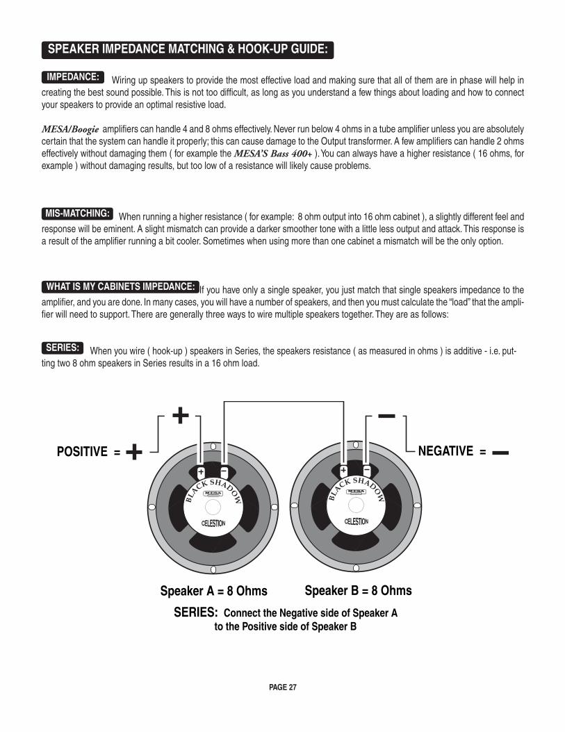
PAGE 27
SPEAKER IMPEDANCE MATCHING & HOOK-UP GUIDE:
IMPEDANCE: Wiring up speakers to provide the most effective load and making sure that all of them are in phase will help in creating the best sound possible. This is not too difficult, as long as you understand a few things about loading and how to connect your speakers to provide an optimal resistive load.
MESA/Boogie amplifiers can handle 4 and 8 ohms effectively. Never run below 4 ohms in a tube amplifier unless you are absolutely certain that the system can handle it properly; this can cause damage to the Output transformer. A few amplifiers can handle 2 ohms effectively without damaging them ( for example the MESA’S Bass 400+ ). You can always have a higher resistance ( 16 ohms, for example ) without damaging results, but too low of a resistance will likely cause problems.
MIS-MATCHING: When running a higher resistance ( for example: 8 ohm output into 16 ohm cabinet ), a slightly different feel and response will be eminent. A slight mismatch can provide a darker smoother tone with a little less output and attack. This response is a result of the amplifier running a bit cooler. Sometimes when using more than one cabinet a mismatch will be the only option.
WHAT IS MY CABINETS IMPEDANCE: If you have only a single speaker, you just match that single speakers impedance to the amplifier, and you are done. In many cases, you will have a number of speakers, and then you must calculate the “load” that the ampli-fier will need to support. There are generally three ways to wire multiple speakers together. They are as follows:
SERIES: When you wire ( hook-up ) speakers in Series, the speakers resistance ( as measured in ohms ) is additive - i.e. put-ting two 8 ohm speakers in Series results in a 16 ohm load.
Speaker A = 8 Ohms Speaker B = 8 Ohms
SERIES: Connect the Negative side of Speaker Ato the Positive side of Speaker B
POSITIVE = NEGATIVE =
BLACK SHADO
W BLACK SHADO
W
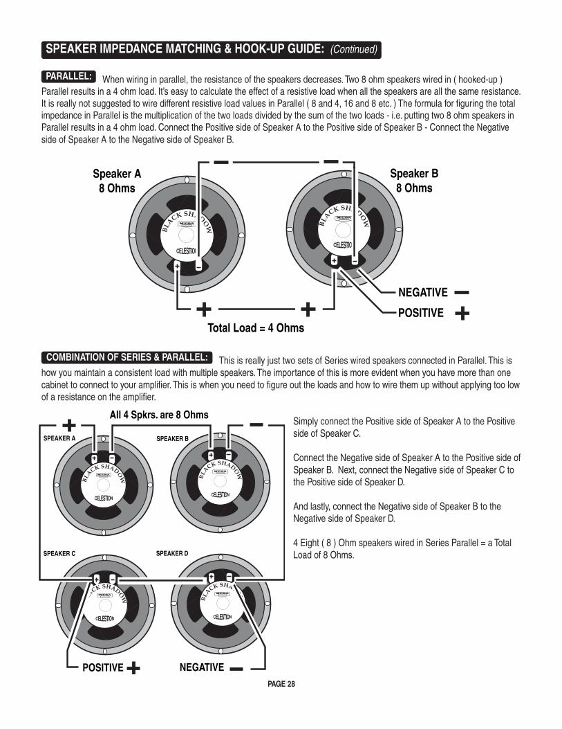
PAGE 28
SPEAKER IMPEDANCE MATCHING & HOOK-UP GUIDE: (Continued)
PARALLEL: When wiring in parallel, the resistance of the speakers decreases. Two 8 ohm speakers wired in ( hooked-up ) Parallel results in a 4 ohm load. It’s easy to calculate the effect of a resistive load when all the speakers are all the same resistance. It is really not suggested to wire different resistive load values in Parallel ( 8 and 4, 16 and 8 etc. ) The formula for figuring the total impedance in Parallel is the multiplication of the two loads divided by the sum of the two loads - i.e. putting two 8 ohm speakers in Parallel results in a 4 ohm load. Connect the Positive side of Speaker A to the Positive side of Speaker B - Connect the Negative side of Speaker A to the Negative side of Speaker B.
COMBINATION OF SERIES & PARALLEL: This is really just two sets of Series wired speakers connected in Parallel. This is
how you maintain a consistent load with multiple speakers. The importance of this is more evident when you have more than one cabinet to connect to your amplifier. This is when you need to figure out the loads and how to wire them up without applying too low of a resistance on the amplifier.
Simply connect the Positive side of Speaker A to the Positive side of Speaker C.
Connect the Negative side of Speaker A to the Positive side of Speaker B. Next, connect the Negative side of Speaker C to the Positive side of Speaker D.
And lastly, connect the Negative side of Speaker B to the Negative side of Speaker D.
4 Eight ( 8 ) Ohm speakers wired in Series Parallel = a Total Load of 8 Ohms.
POSITIVE
Speaker A8 Ohms
Speaker B8 Ohms
NEGATIVE
Total Load = 4 OhmsBL
ACK SHADOW
BLACK SHADO
W
SPEAKER A SPEAKER B
SPEAKER C SPEAKER D
NEGATIVE
All 4 Spkrs. are 8 Ohms
POSITIVE
BLACK SHADO
W
BLACK SHADO
W
BLACK SHADO
W BLACK SHADO
W
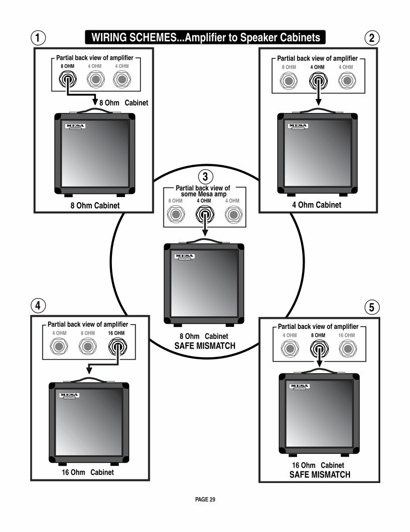
PAGE 29
1 2
54
4 Ohm Cabinet
3
8 OHM 4 OHM 4 OHM
Partial back view of some Mesa amp
8 Ohm CabinetSAFE MISMATCH
WIRING SCHEMES...Amplifier to Speaker Cabinets
4 OHM 8 OHM 16 OHM
Partial back view of amplifier
16 Ohm Cabinet
4 OHM 8 OHM 16 OHM
Partial back view of amplifier
16 Ohm CabinetSAFE MISMATCH
8 OHM 4 OHM 4 OHM
Partial back view of amplifier8 OHM 4 OHM 4 OHM
Partial back view of amplifier
8 Ohm Cabinet
4 Ohm Cabinet8 Ohm Cabinet
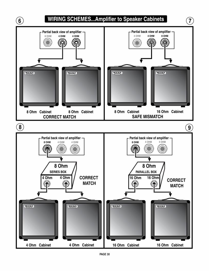
PAGE 30
8 OHM 4 OHM 4 OHM
Partial back view of amplifier
8 Ohm Cabinet 8 Ohm Cabinet
6
8 Ohm Cabinet 16 Ohm Cabinet
8
4 OHM 4 OHM 8 OHM
Partial back view of amplifier
SAFE MISMATCH
8 OHM
Partial back view of amplifier
SERIES BOX
8 Ohm
4 Ohm 4 Ohm
4 Ohm Cabinet 4 Ohm Cabinet
4 OHM 4 OHM 8 OHM
Partial back view of amplifier
PARALLEL BOX
8 Ohm
16 Ohm 16 Ohm
16 Ohm Cabinet 16 Ohm Cabinet
9
4 OHM 4 OHM
7 WIRING SCHEMES...Amplifier to Speaker Cabinets
CORRECT MATCH
CORRECT MATCH
CORRECT MATCH
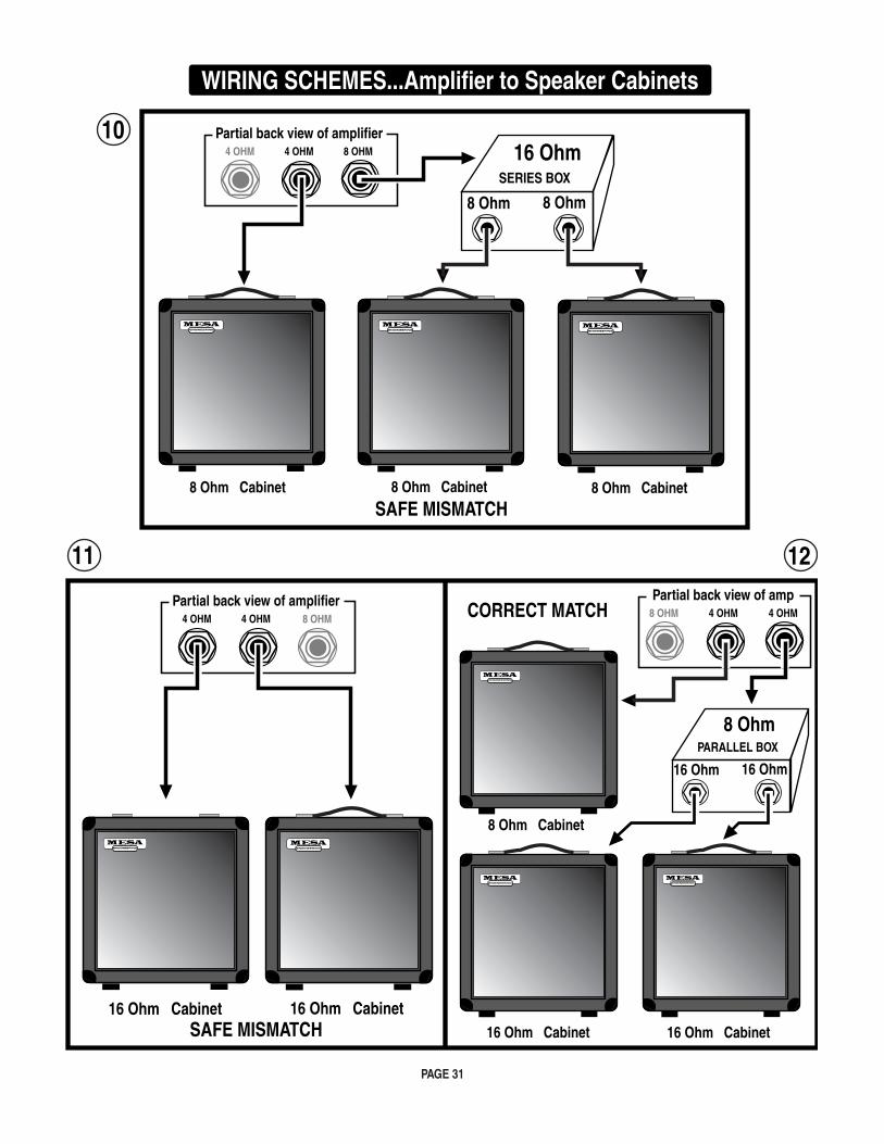
PAGE 31
4 OHM 4 OHM 8 OHM
Partial back view of amplifier
8 Ohm Cabinet 8 Ohm Cabinet
SERIES BOX
16 Ohm
8 Ohm 8 Ohm
8 Ohm Cabinet
10
SAFE MISMATCH
12
4 OHM 4 OHM
Partial back view of amplifier
16 Ohm Cabinet 16 Ohm Cabinet
11
8 OHM
8 Ohm Cabinet
16 Ohm Cabinet 16 Ohm Cabinet
4 OHM4 OHM8 OHM
Partial back view of amp
PARALLEL BOX
8 Ohm
16 Ohm 16 Ohm
WIRING SCHEMES...Amplifier to Speaker Cabinets
CORRECT MATCH
SAFE MISMATCH
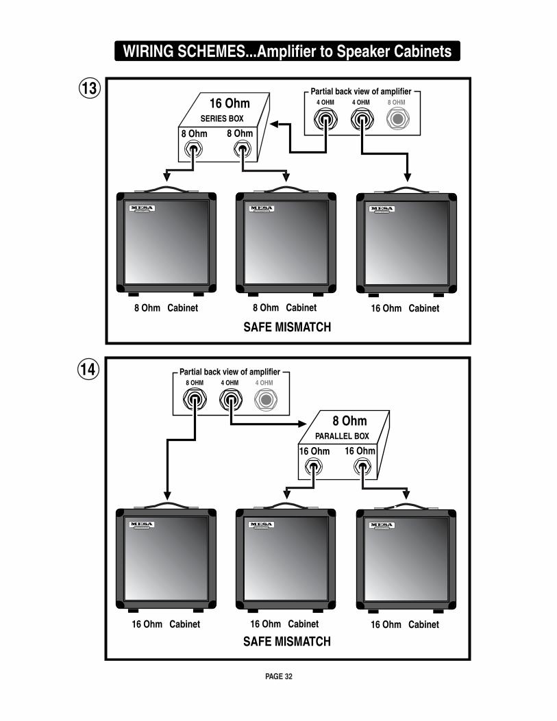
PAGE 32
4 OHM 4 OHM 8 OHM
Partial back view of amplifier
8 Ohm Cabinet 8 Ohm Cabinet
SERIES BOX
16 Ohm
8 Ohm 8 Ohm
16 Ohm Cabinet
13
SAFE MISMATCH
WIRING SCHEMES...Amplifier to Speaker Cabinets
4 OHM4 OHM8 OHM
Partial back view of amplifier
16 Ohm Cabinet 16 Ohm Cabinet
PARALLEL BOX
8 Ohm
16 Ohm 16 Ohm
16 Ohm Cabinet
SAFE MISMATCH
14
PAGE 33
ON TRIODES, PENTODES & IRISHMEN:
With apologies to Friends and Relatives from the Emerald Isle - who will make their appearance soon enough - the humor which follows is dedicated to the memories of Spec McAuliff and Fae (Rafael) McNally, two of the True Greats.
As their numerical references suggest, the terms Diode, Triode and Pentode indicate the number of elements within the vacuum tube i.e. two, three or five. All tubes also require a filament or heater which is not included in the count. Its purpose is to excite elec-trons from the cathode coating by raising the temperature such that they are able to boil out of the electron-rich coating material and form a cloud of free electrons in the vacuum space surrounding the cathode.
Although the term filament and heater are often used interchangeably, there are specific differences: A filament is a directly heated cathode where cathode coating is applied directly to the heating element. Examples are 5U4 twin diode rectifier and 300B triode amplifier tubes. A heater, on the other hand, is a heating element which is separate from the cathode and is usually inserted within the tubular cathode sleeve. Examples are 12AX7 twin triode amplifier and 6V6 or EL84 beam power pentode tubes. In all cases this fundamental aspect of each tube’s construction is clearly visible, especially when the heating element is glowing red hot.
The cathode, then, would be considered the first numbered element because it is the source of the electrons. The word itself is from the Greek literally meaning completely down, which implies a sense of central origin - like the center of the earth where Tone begins. It might be said that an ecstatic audiophile experiences a positive catharsis, his soul being purified when his system transports him to Audio Nirvana. The only trouble with taking this positive imagery too far is that the cathode is, unfortunately, negative... at least electrically speaking. However this is easily remembered since virtually all musicians and audiophiles have also experienced the more common negative catharsis when they emerge from the emotional rebirth kicking and screaming in rage and frustration.
Once heated, the intrinsically negative electrons are energetic little fellows of almost no mass. Thus they may be accelerated al-most instantaneously and will travel through a vacuum a nearly the speed of light. Being of like, negative charge, they tend to repel one another and thus within the electron cloud surrounding the cathode, there is much jostling and elbowing as each one tries to maintain his distance from all the others... unless there is a strong and universal attraction from an outside influence.
Visualize, if you will, a group of sub-atomic Irishmen milling about and in a repellent, negative state of mind. All are scowling and none wants to have anything to do with the other. Now introduce a strong attraction say, a public bar, and you can easily picture an orderly, if rapid movement of the lot in a single direction. This is what happens when a positively charged element called the anode or plate is introduced into the vacuum.
The plate is the large metal element most prominently visible through the glass of an electron tube. It is the outermost element of a tube’s structure and it surrounds all the others. The cathode is at the center radiating electrons outwards. As higher and higher positive voltage is applied to the plate, the attraction for the electrons surrounding the cathode is increased and with nothing stand-ing in the way, full uninhibited flow to the plate occurs... sort of like removing the doors and offering free drinks to the crowd of surly Irishmen milling around outside. As electrons flow to the plate, the space charge will continually be replenished by further ‘boiling’ of the hot, electron-rich cathode as you can easily imagine other Irishmen impatiently taking up the places of those who’ve gone inside - until the entire village is deserted.
Now, where do they come from and how do they emerge? Well, a grand and elegant lady once showed me how to revive flat cham-pagne: She dropped a raisin into the glass. There was a dramatic and immediate increase in effervescence with the introduction of a cathoding surface. Thousands of tiny bubbles suddenly appeared - and continued to flow from the raisin. Of course the bubbles were made up of gas dissolved in the beverage, but the analogy makes it easy to visualize the loosely bound electrons dissolved in the rich cathode coating as they effervesce from its heated surface.
But back to the electron flow. If the electrons are strongly attracted to a positively charged plate, then it follows that they are strongly repelled by a negatively charged plate and they are. Thus, if an alternating current - such as comes from a transformer - is applied to the plate, electrons will flow only during the times when the plate is positively charged. During periods of negative plate charge, electron flow is stopped and the space charge of electrons remains compressed in the area around the cathode.
PAGE 34
ON TRIODES, PENTODES & IRISHMEN: (Continued) Thus a diode tube - one with a cathode and an anode - is mostly used to rectify alternating current into direct current by passing it without restriction, but in one direction only. This also explains why closing time is strictly enforced at Irish pubs: During normal operation, the traffic flow is similarly unimpeded and uni-directional toward the bar and this process rectifies the work-day negativity. It goes without saying that no one leaves as long as the atmosphere around the bar remains positively charged. TRIODES: This section is a continuing technical treatise on the workings of Irish Pubs but to make it easier for the layman to
understand, it is explained in terms of vacuum tube technology. Enter the original bar - free beer and no doors. Well, it turns out that some control over the flow can be a necessary and useful advantage. This led to the invention of those swinging louvered saloon doors which are open at the top and bottom. They are patterned after the control grid of the vacuum tube, which is a loosely wound coil of thin wire located between the cathode and the plate.
In a Triode the plate is always positively charged with high voltage D.C. and even though the grid is blocking the path, those nega-tive electrons can still FEEL the strong attraction - just as the Irishmen can see in through the louvers of the bar doors. They know what pleasures lie beyond, but to get there requires overcoming the negative influences controlling the access. This negative influ-ence is typically called a Bias. In electronic terms that means the grid is supplied with a voltage which is slightly MORE NEGATIVE than the already negative electrons. The more negative the Bias, the more it tends to neutralize the attraction of the plate and repel the electrons back toward the cathode.
The Irish can be similarly charged with Bias, but unless you are Irish yourself, this type of Biasing may be more difficult to under-stand. The effect is similar though: The more negative the Bias, the more it impedes forward progress. Generally speaking though, the electronic Bias of the grid is easiest to overcome, and for two main reasons: First, the Bias is set - like the bar doors - to allow some passage. Second, the grid is mostly NOT THERE, like the louvered doors which are mostly open spaces. Unlike the plate which is solid, the grid is like a coiled bed spring. It can create a repelling field but mostly it’s empty space in between widely sepa-rated windings of wire. It’s very easy to control the electrons as they pass through the grid’s force field: Changing the grid voltage only slightly will have an enormous effect on how much current flows through... and that’s what AMPLIFICATION is: a small change in voltage at the grid causing a large change in current flowing to the plate.
The purpose of the louvered bar doors is similar to that of the grid, namely, to give momentary pause while still revealing the promise within. Hesitation mostly gives way to temptation, but there are those few stalwart Irishmen who think twice and decide to come back later. Most just pause slightly then go on through. That is the purpose of the bar doors: to prevent everyone from crowding in all at once - and as the door is made less of a barrier, wider spaces between the louvers, more of the bar’s attractive influence is felt outside thus amplifying the customer flow and increasing the crowd at the bar.
PENTODES: Occasionally though, bar doors - even the louvered type - were found to be too effective, and too many customers turned away. Something further was needed to increase the attraction of the bar and overcome the resistance created by the door. Thus the cocktail waitress was invented. Once again the idea was inspired by the vacuum tube. It had been discovered in some tubes, often large power types, that the distance to the plate was too great to attract enough electrons past the negative influence of the control grid. So another grid coil of fine wire was inserted between the first grid and the plate. This was called the screen grid and carrying a highly positive charge, it functioned as a “bait” for the plate.
In a properly designed power tube such as an EL84 or a 6V6, the windings of the screen grid are precisely aligned to fall in the shadow of the control grid. This way the electrons responding to the pull of the screen grid are lined up in sheets as they pass be-tween windings of the inner control grid... only to find that they have been fooled! Once past the control grid and drawn toward the screen grid, they discover...there’s almost nothing there. The path they’re on has them aligned to zing straight through the spaces BETWEEN screen grid windings. So rather than a close and personal encounter, they just fly on past - and once they’re out that far, there’s no stopping them. The influence of the plate takes over and - being solid metal and of the highest positive attraction - it is at this final destination that the electrons congregate.
PAGE 35
PENTODES: (Continued) Thus the proper cocktail waitress - visible through the louvers - is scantily clad so as to be all the more effective at reinforcing the attractive influence of her bar and by being located in between the door and the bar, she serves as bait to lure customers past the door’s negative influence. Once through the door however, it is the rare Irishman who actually comes in personal contact with the cocktail waitress as, for all intents and purposes, she - like the screen grid - turns out to be a vanishing illusion. Yet, having come this far, the solid influence of the bar itself now takes over and attracts the customers to congregate, hav-ing happily reached their destination.
If you’re still following this and haven’t lost track of the count, you’ll know we’re still one element short of the five needed to make a Pentode. This last part is a pair of beam-confining shields which being negatively charged, serve to direct the flow right toward the plate. This is much the way a short entrance hall to the bar prevents wandering accidentally into the Men’s room on the way.
Once at the bar though, the circuit is complete and the process of soul-nourishing works its ritual magic. Biases having been over-come, illusory nightingales having vanished, the spirits truly soar and the once surly Irishmen now are filled with warmth, wit and kindred friendship, enjoying the music and glowing nicely with their heaters on.
With appreciative thanks to the inhabitants of the Land of the Leprechaun, we have now concluded our little diversion into the mechanics of proper bar lay-out.
A feature article by Randall SmithDesigner / President
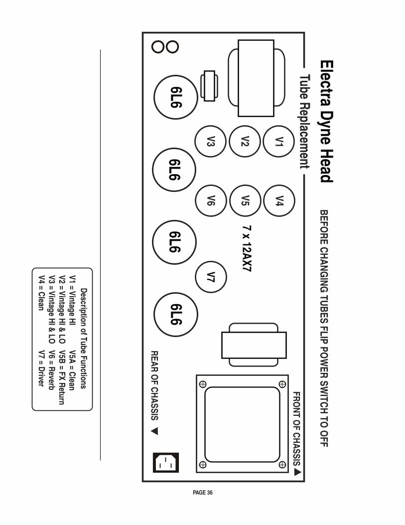
PAGE 36
V1 = Vintage HIV2 = Vintage HI & LOV3 = Vintage HI & LOV4 = Clean
V5A = CleanV5B = FX ReturnV6 = ReverbV7 = Driver
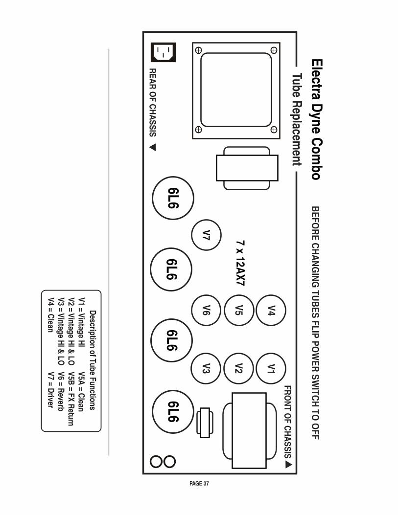
PAGE 37
V1 = Vintage HIV2 = Vintage HI & LOV3 = Vintage HI & LOV4 = Clean
V5A = CleanV5B = FX ReturnV6 = ReverbV7 = Driver
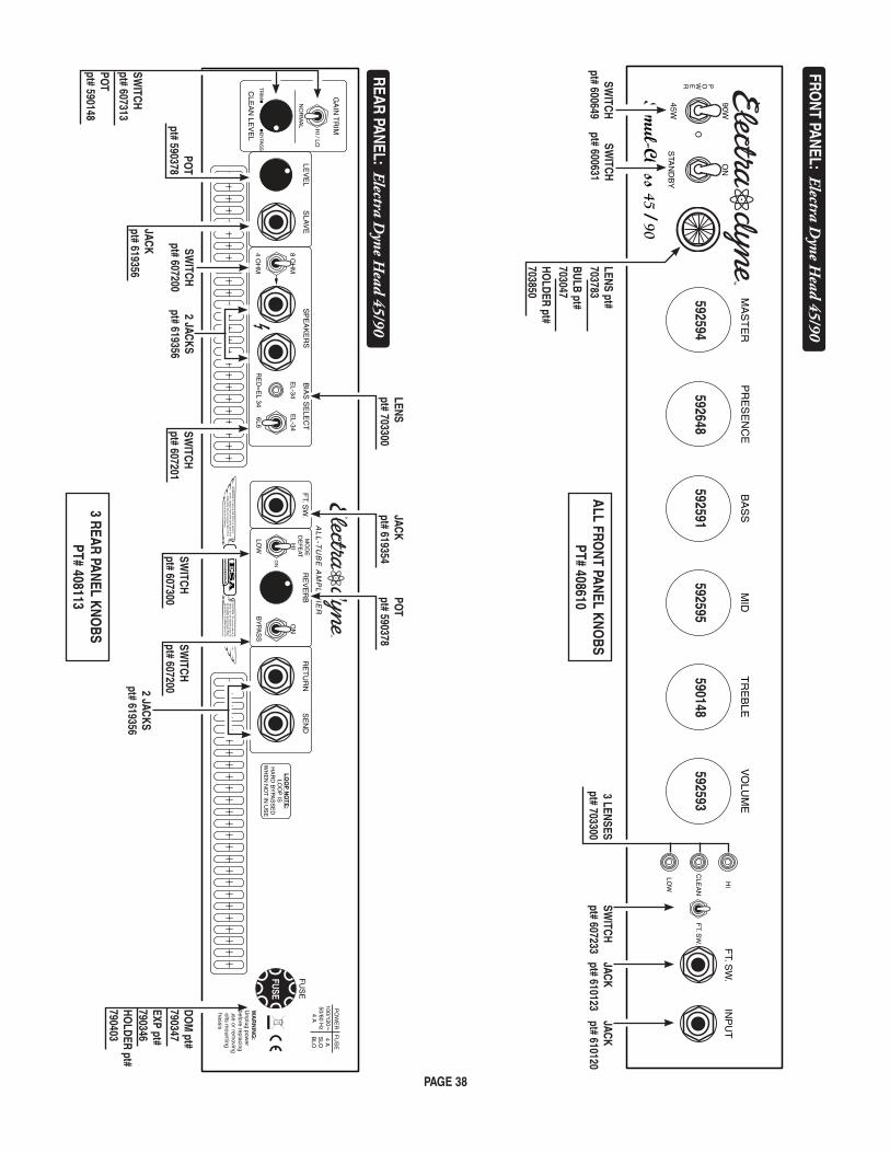
PAGE 38
3 REAR PANEL KNOBS
PT# 408113
FRONT PANEL: Electra D
yne Head 45/90
ALL FRONT PANEL KNO
BSPT# 408610
INP
UT
FT. S
W.
CLE
AN
HI
LOW
FT. S
W.
VO
LUM
ET
RE
BLE
MID
BA
SS
PR
ES
EN
CE
MA
ST
ER
45W
90W
O
STA
ND
BY
ON
Simul-Class 45 / 90
POWER
592593
JACKpt# 610120
JACKpt# 610123
SWITCH
pt# 607233
590148592595
592591592648
592594
SWITCH
pt# 600649SW
ITCHpt# 600631
3 LENSESpt# 703300
LENS pt#703783BULB pt#703047HO
LDER pt#703850
FUS
E
BY
PAS
S
ON
HI
LOW
ON
MO
DE
DE
FE
AT
6L6
EL-34
EL-34
8 OH
M
4 OH
M
SE
ND
RE
TU
RN
RE
VE
RB
FT. S
W.
BIA
S S
ELE
CT
SP
EA
KE
RS
SLA
VE
LEV
EL
RE
D=
EL 34
AL
L-T
UB
E A
MP
LIF
IER
LO
OP
NO
TE
:LO
OP
ISH
AR
D B
YPA
SS
ED
WH
EN
NO
T IN
US
E
100/120~50/60 H
z4 A
4 AS
LOB
LO
FUSE
CLE
AN
LEV
EL
GA
IN T
RIM
NO
RM
AL
HI / LO
CLE
AN
TR
IMB
YPA
SS
DOM
pt#790347EXP pt#790346HO
LDER pt#790403
SWITCH
pt# 607201SW
ITCHpt# 607300
SWITCH
pt# 607200
SWITCH
pt# 607200
JACKpt# 619356
LENSpt# 703300
JACKpt# 619354
POT
pt# 590378
POT
pt# 590378
REAR PANEL: Electra Dyne H
ead 45/90
2 JACKSpt# 619356
2 JACKSpt# 619356
SWITCH
pt# 607313
POT
pt# 590148
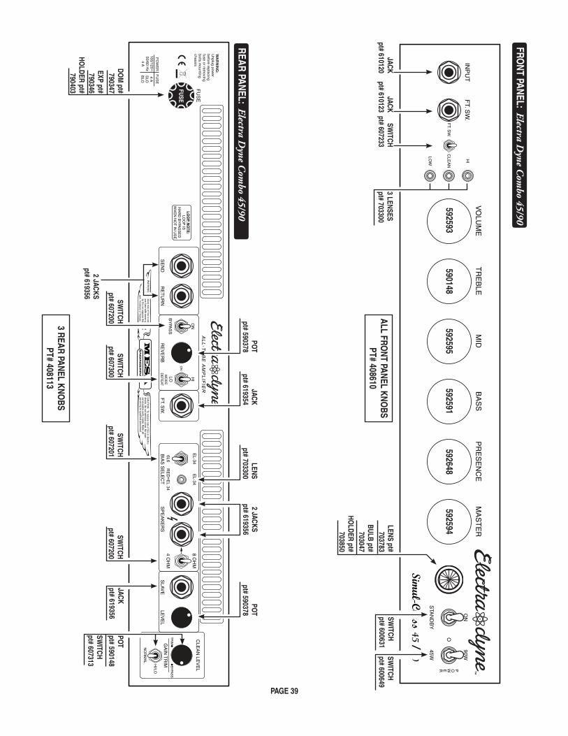
PAGE 39
ALL FRONT PANEL KNO
BSPT# 408610
3 REAR PANEL KNOBS
PT# 408113
FUS
E
BY
PAS
S
ON
HI
LO
ON
MO
DE
DE
FE
AT
6L6
EL-34
EL-34
8 OH
M
4 OH
MS
EN
DR
ET
UR
NR
EV
ER
BF
T. SW
.B
IAS
SE
LEC
TS
PE
AK
ER
SS
LAV
ELE
VE
LR
ED
=EL 34
LO
OP
NO
TE
:LO
OP
ISH
AR
D B
YPA
SS
ED
WH
EN
NO
T IN
US
E
100/120~50/60 H
z4 A
4 AS
LOB
LO
AL
L-T
UB
E A
MP
LIF
IER
FUSE
GA
IN T
RIM
NO
RM
AL
HI/LO
CLE
AN
CLE
AN
LEV
EL
TR
IMB
YPA
SS
DOM
pt#790347
EXP pt#790346
HOLDER pt#
790403
SWITCH
pt# 607201SW
ITCHpt# 607300
SWITCH
pt# 607200 SW
ITCHpt# 607200
JACKpt# 619356
LENSpt# 703300
JACKpt# 619354
POT
pt# 590378PO
Tpt# 590378
REAR PANEL: Electra Dyne C
ombo 45/90
INP
UT
FT. S
W.
CLE
AN
HI
LOW
FT. S
W.
VO
LUM
ET
RE
BLE
MID
BA
SS
PR
ES
EN
CE
MA
ST
ER
45W
90W
O
STA
ND
BY
ON
Simul-Class 45 / 90
POWER
592593
JACKpt# 610120
JACKpt# 610123
SWITCH
pt# 607233
FRONT PANEL: Electra D
yne Com
bo 45/90
590148592595
592591592648
592594
SWITCH
pt# 600649SW
ITCHpt# 600631
3 LENSESpt# 703300
LENS pt#703783
BULB pt#703047
HOLDER pt#
703850
2 JACKSpt# 619356
2 JACKSpt# 619356
SWITCH
pt# 607313
POT
pt# 590148
NOTES

®
®

®
09/17/10