cabeca a valvulas peavey jsx joe satriani signature - manual sonigate
DESCRIPTION
™ Joe Satriani Signature All-Tube Amplifier 10 For more information on other great Peavey products, visit your local Peavey dealer or go online at www.peavey.comTRANSCRIPT
10
JSX
For more information on other great Peavey products, visit your local Peavey dealer or go online at www.peavey.com
™ Joe Satriani Signature All-Tube Amplifier
Intended to alert the user to the presence of uninsulated “dangerous voltage” within the product’s enclosure that may be of sufficient magnitude to constitute a risk of electric shock to persons.
Intended to alert the user of the presence of important operating and maintenance (servicing) instructions in the literature accompanying the product.
CAUTION: Risk of electrical shock — DO NOT OPEN! CAUTION: To reduce the risk of electric shock, do not remove cover. No user serviceable parts inside. Refer servicing to qualified service personnel.
WARNING: To prevent electrical shock or fire hazard, do not expose this appliance to rain or moisture. Before using this appliance, read the operating guide for further warnings.
Este símbolo tiene el propósito, de alertar al usuario de la presencia de “(voltaje) peligroso” sin aislamiento dentro de la caja del producto y que puede tener una magnitud suficiente como para constituir riesgo de descarga eléctrica.
Este símbolo tiene el propósito de alertar al usario de la presencia de Instrucciones importantes sobre la operación y mantenimiento en la información que viene con el producto.
PRECAUCION: Riesgo de descarga eléctrica ¡NO ABRIR! PRECAUCION: Para disminuír el riesgo de descarga eléctrica, no abra la cubierta. No hay piezas útiles dentro. Deje todo mantenimiento en manos del personal técnico cualificado.
ADVERTENCIA: Para evitar descargas eléctricas o peligro de incendio, no deje expuesto a la lluvia o humedad este aparato Antes de usar este aparato, Iea más advertencias en la guía de operación.
Ce symbole est utilisé dans ce manuel pour indiquer à l’utilisateur la présence d’une tension dangereuse pouvant être d’amplitude suffisante pour constituer un risque de choc électrique.
Ce symbole est utilisé dans ce manuel pour indiquer à l’utilisateur qu’il ou qu’elle trouvera d’importantes instructions concernant l’utilisation et l’entretien de l’appareil dans le paragraphe signalé.
ATTENTION: Risques de choc électrique — NE PAS OUVRIR!ATTENTION: Afin de réduire le risque de choc électrique, ne pas enlever le couvercle. Il ne se trouve à l’intérieur aucune pièce pouvant être reparée par l’utilisateur. Confiez I’entretien et la réparation de l’appareil à un réparateur Peavey agréé.
AVERTISSEMENT: Afin de prévenir les risques de décharge électrique ou de feu, n’exposez pas cet appareil à la pluie ou à l’humidité. Avant d’utiliser cet appareil, lisez attentivement les avertissements supplémentaires de ce manuel.
Dieses Symbol soll den Anwender vor unisolierten gefährlichen Spannungen innerhalb des Gehäuses warnen, die von Ausreichender Stärke sind, um einen elektrischen Schlag verursachen zu können.
Dieses Symbol soll den Benutzer auf wichtige Instruktionen in der Bedienungsanleitung aufmerksam machen, die Handhabung und Wartung des Produkts betreffen.
VORSICHT: Risiko — Elektrischer Schlag! Nicht öffnen! VORSICHT: Um das Risiko eines elektrischen Schlages zu vermeiden, nicht die Abdeckung enfernen. Es befinden sich keine Teile darin, die vom Anwender repariert werden könnten. Reparaturen nur von qualifiziertem Fachpersonal durchführen lassen.
ACHTUNG: Um einen elektrischen Schlag oder Feuergefahr zu vermeiden, sollte dieses Gerät nicht dem Regen oder Feuchtigkeit ausgesetzt werden. Vor Inbetriebnahme unbedingt die Bedienungsanleitung lesen.
2
IMPORTANT SAFETY INSTRUCTIONS
WARNING: When using electrical products, basic cautions should always be followed, including the following:
1. Read these instructions.
2. Keep these instructions.
3. Heed all warnings.
4. Follow all instructions.
5. Do not use this apparatus near water.
6. Clean only with a dry cloth.
7. Do not block any of the ventilation openings. Install in accordance with manufacturer’s instructions.
8. Do not install near any heat sources such as radiators, heat registers, stoves or other apparatus (including amplifiers) that produce heat.
9. Do not defeat the safety purpose of the polarized or grounding-type plug. A polarized plug has two blades with one wider than the other. A grounding type plug has two blades and a third grounding plug. The wide blade or third prong is provided for your safety. If the provided plug does not fit into your outlet, consult an electrician for replacement of the obsolete outlet.
10. Protect the power cord from being walked on or pinched, particularly at plugs, convenience receptacles, and the point they exit from the apparatus.
11. Note for UK only: If the colors of the wires in the mains lead of this unit do not correspond with the terminals in your plug‚ proceed as follows:
a) The wire that is colored green and yellow must be connected to the terminal that is marked by the letter E‚ the earth symbol‚ colored green or colored green and yellow.
b) The wire that is colored blue must be connected to the terminal that is marked with the letter N or the color black.
c) The wire that is colored brown must be connected to the terminal that is marked with the letter L or the color red.
12. Only use attachments/accessories provided by the manufacturer.
13. Use only with a cart, stand, tripod, bracket, or table specified by the manufacturer, or sold with the apparatus. When a cart is used, use caution when moving the cart/apparatus combination to avoid injury from tip-over.
14. Unplug this apparatus during lightning storms or when unused for long periods of time.
15. Refer all servicing to qualified service personnel. Servicing is required when the apparatus has been damaged in any way, such as power-supply cord or plug is damaged, liquid has been spilled or objects have fallen into the apparatus, the apparatus has been exposed to rain or moisture, does not operate normally, or has been dropped.
16. Never break off the ground pin. Write for our free booklet “Shock Hazard and Grounding.” Connect only to a power supply of the type marked on the unit adjacent to the power supply cord.
17. If this product is to be mounted in an equipment rack, rear support should be provided.
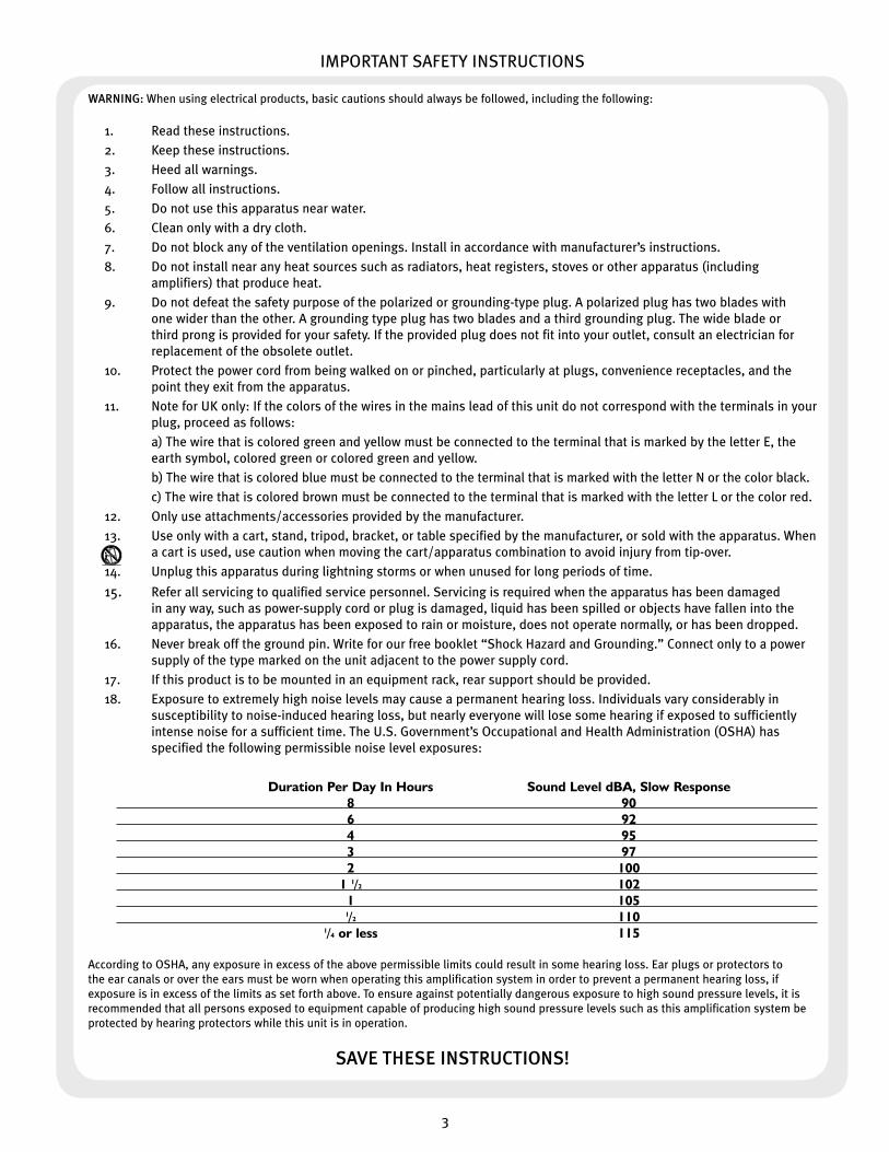
18. Exposure to extremely high noise levels may cause a permanent hearing loss. Individuals vary considerably in susceptibility to noise-induced hearing loss, but nearly everyone will lose some hearing if exposed to sufficiently intense noise for a sufficient time. The U.S. Government’s Occupational and Health Administration (OSHA) has specified the following permissible noise level exposures:
Duration Per Day In Hours Sound Level dBA, Slow Response 8 90 6 92 4 95 3 97 2 100 1 1/2 102 1 105 1/2 110 1/4 or less 115
According to OSHA, any exposure in excess of the above permissible limits could result in some hearing loss. Ear plugs or protectors to the ear canals or over the ears must be worn when operating this amplification system in order to prevent a permanent hearing loss, if exposure is in excess of the limits as set forth above. To ensure against potentially dangerous exposure to high sound pressure levels, it is recommended that all persons exposed to equipment capable of producing high sound pressure levels such as this amplification system be protected by hearing protectors while this unit is in operation.
SAVE THESE INSTRUCTIONS!
3

Congratulations on purchasing a Peavey JSX guitar amplifier. The
JSX is a guitar player’s dream come true, an amp that delivers
superior sound quality and high performance for any style of
guitar playing. Only the finest materials are used to create this
great-sounding, rugged, tour-worthy and very unique-looking tone
machine. I hope you like this amp as much as I do!
ENGLISHF R O N T PA N E L
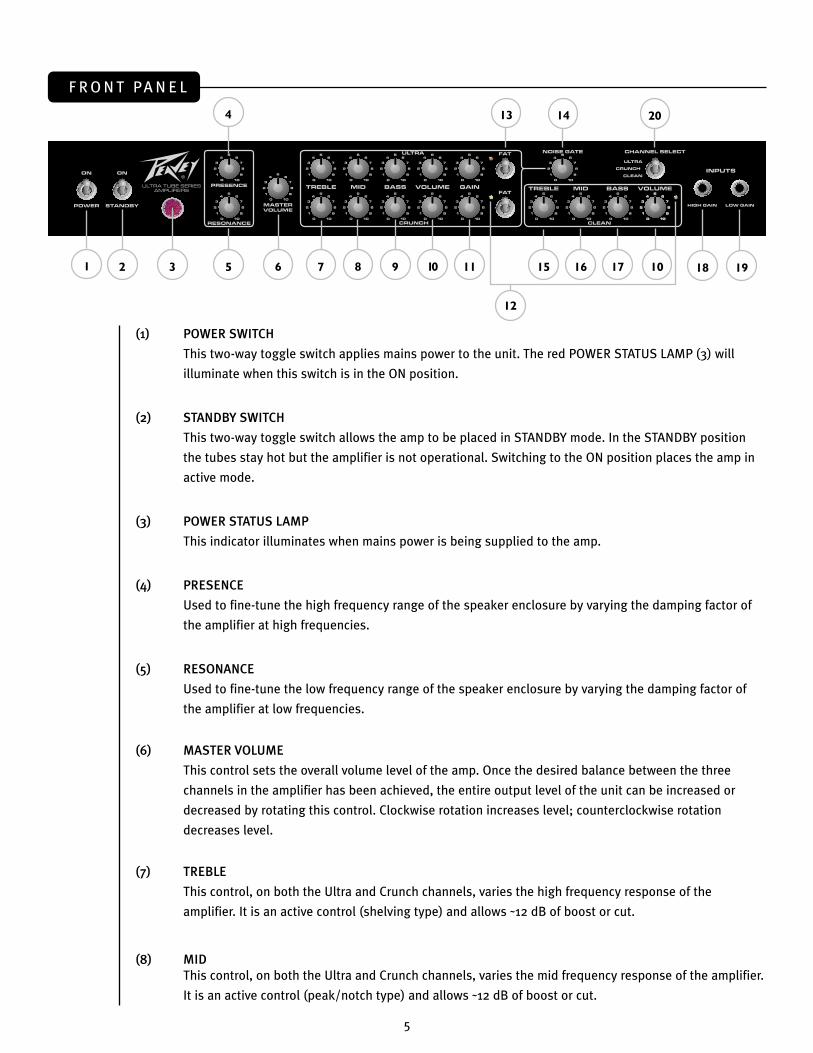
(1) POWER SWITCH
This two-way toggle switch applies mains power to the unit. The red POWER STATUS LAMP (3) will
illuminate when this switch is in the ON position.
(2) STANDBY SWITCH
This two-way toggle switch allows the amp to be placed in STANDBY mode. In the STANDBY position
the tubes stay hot but the amplifier is not operational. Switching to the ON position places the amp in
active mode.
(3) POWER STATUS LAMP
This indicator illuminates when mains power is being supplied to the amp.
(4) PRESENCE
Used to fine-tune the high frequency range of the speaker enclosure by varying the damping factor of
the amplifier at high frequencies.
(5) RESONANCE
Used to fine-tune the low frequency range of the speaker enclosure by varying the damping factor of
the amplifier at low frequencies.
(6) MASTER VOLUME
This control sets the overall volume level of the amp. Once the desired balance between the three
channels in the amplifier has been achieved, the entire output level of the unit can be increased or
decreased by rotating this control. Clockwise rotation increases level; counterclockwise rotation
decreases level.
(7) TREBLE
This control, on both the Ultra and Crunch channels, varies the high frequency response of the
amplifier. It is an active control (shelving type) and allows ˜12 dB of boost or cut.
(8) MID This control, on both the Ultra and Crunch channels, varies the mid frequency response of the amplifier.
It is an active control (peak/notch type) and allows ˜12 dB of boost or cut.
Features
• Three 12AX7 preamp tubes
• Four EL34 power amp tubes driven by a 12AX7
• Power amp convertible to use four 6L6GC tubes
• Footswitchable effects loop with independent send and return controls
• Resonance and presence damping controls
• Fully adjustable noise gate circuitry on Ultra and Crunch channels
• Line out with level control
• Cabinet impedance switch (4, 8 or 16 Ohms)
• Heavy duty power, standby and channel select toggle switches
• Classic power status indicator lamp
• Chrome-plated brass control knobs
1 3 5 7 9 11
13
152
4
6 8 10
14
16 10
12
19
20
17 18
Joe Satriani
™
4
Congratulations on purchasing a Peavey JSX guitar amplifier. The
JSX is a guitar player’s dream come true, an amp that delivers
superior sound quality and high performance for any style of
guitar playing. Only the finest materials are used to create this
great-sounding, rugged, tour-worthy and very unique-looking tone
machine. I hope you like this amp as much as I do!
ENGLISHF R O N T PA N E L
(1) POWER SWITCH
This two-way toggle switch applies mains power to the unit. The red POWER STATUS LAMP (3) will
illuminate when this switch is in the ON position.
(2) STANDBY SWITCH
This two-way toggle switch allows the amp to be placed in STANDBY mode. In the STANDBY position
the tubes stay hot but the amplifier is not operational. Switching to the ON position places the amp in
active mode.
(3) POWER STATUS LAMP
This indicator illuminates when mains power is being supplied to the amp.
(4) PRESENCE
Used to fine-tune the high frequency range of the speaker enclosure by varying the damping factor of
the amplifier at high frequencies.
(5) RESONANCE
Used to fine-tune the low frequency range of the speaker enclosure by varying the damping factor of
the amplifier at low frequencies.
(6) MASTER VOLUME
This control sets the overall volume level of the amp. Once the desired balance between the three
channels in the amplifier has been achieved, the entire output level of the unit can be increased or
decreased by rotating this control. Clockwise rotation increases level; counterclockwise rotation
decreases level.
(7) TREBLE
This control, on both the Ultra and Crunch channels, varies the high frequency response of the
amplifier. It is an active control (shelving type) and allows ˜12 dB of boost or cut.
(8) MID This control, on both the Ultra and Crunch channels, varies the mid frequency response of the amplifier.
It is an active control (peak/notch type) and allows ˜12 dB of boost or cut.
Features
• Three 12AX7 preamp tubes
• Four EL34 power amp tubes driven by a 12AX7
• Power amp convertible to use four 6L6GC tubes
• Footswitchable effects loop with independent send and return controls
• Resonance and presence damping controls
• Fully adjustable noise gate circuitry on Ultra and Crunch channels
• Line out with level control
• Cabinet impedance switch (4, 8 or 16 Ohms)
• Heavy duty power, standby and channel select toggle switches
• Classic power status indicator lamp
• Chrome-plated brass control knobs
1 3 5 7 9 11
13
152
4
6 8 10
14
16 10
12
19
20
17 18
Joe Satriani
™
5
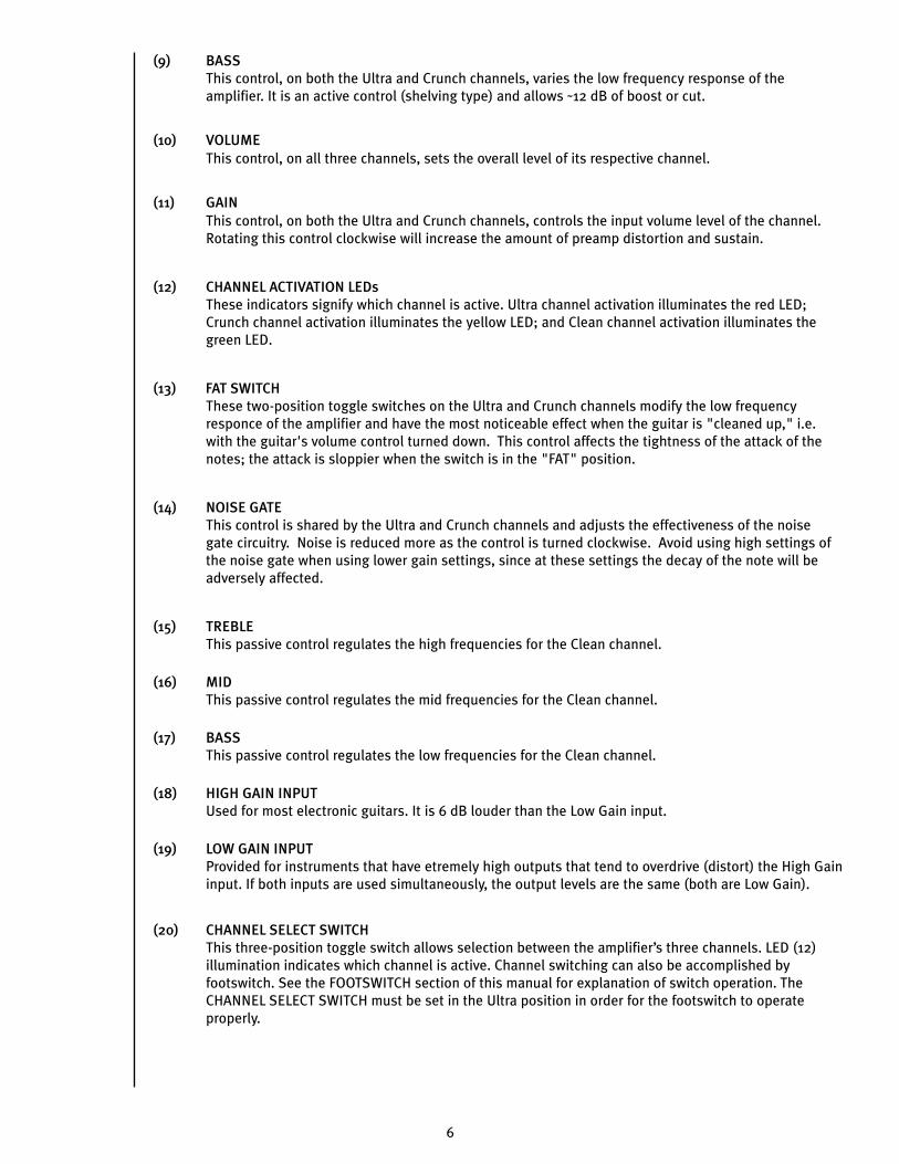
R E A R PA N E L (9) BASS
This control, on both the Ultra and Crunch channels, varies the low frequency response of the amplifier. It is an active control (shelving type) and allows ˜12 dB of boost or cut.
(10) VOLUMEThis control, on all three channels, sets the overall level of its respective channel.
(11) GAINThis control, on both the Ultra and Crunch channels, controls the input volume level of the channel. Rotating this control clockwise will increase the amount of preamp distortion and sustain.
(12) CHANNEL ACTIVATION LEDsThese indicators signify which channel is active. Ultra channel activation illuminates the red LED; Crunch channel activation illuminates the yellow LED; and Clean channel activation illuminates the green LED.
(13) FAT SWITCHThese two-position toggle switches on the Ultra and Crunch channels modify the low frequency responce of the amplifier and have the most noticeable effect when the guitar is "cleaned up," i.e. with the guitar's volume control turned down. This control affects the tightness of the attack of the notes; the attack is sloppier when the switch is in the "FAT" position.
(14) NOISE GATEThis control is shared by the Ultra and Crunch channels and adjusts the effectiveness of the noise gate circuitry. Noise is reduced more as the control is turned clockwise. Avoid using high settings of the noise gate when using lower gain settings, since at these settings the decay of the note will be adversely affected.
(15) TREBLEThis passive control regulates the high frequencies for the Clean channel.
(16) MIDThis passive control regulates the mid frequencies for the Clean channel.
(17) BASSThis passive control regulates the low frequencies for the Clean channel.
(18) HIGH GAIN INPUTUsed for most electronic guitars. It is 6 dB louder than the Low Gain input.
(19) LOW GAIN INPUTProvided for instruments that have etremely high outputs that tend to overdrive (distort) the High Gain input. If both inputs are used simultaneously, the output levels are the same (both are Low Gain).
(20) CHANNEL SELECT SWITCHThis three-position toggle switch allows selection between the amplifier’s three channels. LED (12) illumination indicates which channel is active. Channel switching can also be accomplished by footswitch. See the FOOTSWITCH section of this manual for explanation of switch operation. The CHANNEL SELECT SWITCH must be set in the Ultra position in order for the footswitch to operate properly.
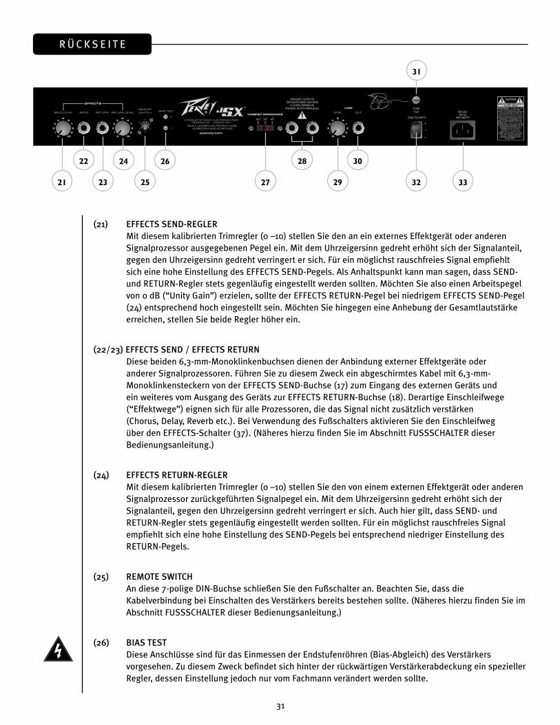
(21) EFFECTS SEND LEVEL
This calibrated (0 – 10) control sets the level of signal being sent to external effects and/or signal
processors. Clockwise rotation increases the amount of signal being sent; counterclockwise rotation
decreases the amount. For the quietest operation, the EFFECTS SEND LEVEL should be set as high as
possible. Generally, the SEND and RETURN levels should be set oppositely. If the EFFECTS SEND LEVEL
is set low, the EFFECTS RETURN LEVEL (24) is set high to achieve unity gain. If volume boost is desired,
turn both controls to higher settings.
(22/23) EFFECTS SEND/EFFECTS RETURN
These 1/4" mono (TS) jacks allow signal to be sent to and returned from external effects and/or signal
processors. Using shielded cables with 1/4" mono (TS) phone plugs, patch from EFFECTS SEND to
the input of the external device and from the output of the external device to EFFECTS RETURN. Only
devices that do not increase signal gain should be used in this effects loop (chorus, delay, reverb, etc.).
If the footswitch is used, the EFFECTS SELECTOR (37) switch must be depressed to activate the effects
loop. See the FOOTSWITCH section of this manual for explanation of switch operation.
(24) EFFECTS RETURN LEVEL
This calibrated (0 – 10) control sets the level of signal being returned from external effects and/or
signal processors. Clockwise rotation increases the amount of signal being returned; counterclockwise
rotation decreases the amount. Again, SEND and RETURN levels should be set oppositely, with the
SEND level being high and the RETURN level low to ensure the quietest operation.
(25) REMOTE SWITCH
This seven-pin DIN connector is provided for the connection of the remote footswitch. The footswitch
cable should be connected before the amp is powered up. See the FOOTSWITCH section of this manual
for an explanation of switch operation.
(26) BIAS TEST TERMINALS
These terminals are provided to measure the bias of the amplifier’s power tubes. A knob behind the
back panel grill allows for adjustment. Bias adjustment should only be done by a qualified technician.
22 24 26
21 25 27 2923
28 30
32
31
33
6

R E A R PA N E L (9) BASS
This control, on both the Ultra and Crunch channels, varies the low frequency response of the amplifier. It is an active control (shelving type) and allows ˜12 dB of boost or cut.
(10) VOLUMEThis control, on all three channels, sets the overall level of its respective channel.
(11) GAINThis control, on both the Ultra and Crunch channels, controls the input volume level of the channel. Rotating this control clockwise will increase the amount of preamp distortion and sustain.
(12) CHANNEL ACTIVATION LEDsThese indicators signify which channel is active. Ultra channel activation illuminates the red LED; Crunch channel activation illuminates the yellow LED; and Clean channel activation illuminates the green LED.
(13) FAT SWITCHThese two-position toggle switches on the Ultra and Crunch channels modify the low frequency responce of the amplifier and have the most noticeable effect when the guitar is "cleaned up," i.e. with the guitar's volume control turned down. This control affects the tightness of the attack of the notes; the attack is sloppier when the switch is in the "FAT" position.
(14) NOISE GATEThis control is shared by the Ultra and Crunch channels and adjusts the effectiveness of the noise gate circuitry. Noise is reduced more as the control is turned clockwise. Avoid using high settings of the noise gate when using lower gain settings, since at these settings the decay of the note will be adversely affected.
(15) TREBLEThis passive control regulates the high frequencies for the Clean channel.
(16) MIDThis passive control regulates the mid frequencies for the Clean channel.
(17) BASSThis passive control regulates the low frequencies for the Clean channel.
(18) HIGH GAIN INPUTUsed for most electronic guitars. It is 6 dB louder than the Low Gain input.
(19) LOW GAIN INPUTProvided for instruments that have etremely high outputs that tend to overdrive (distort) the High Gain input. If both inputs are used simultaneously, the output levels are the same (both are Low Gain).
(20) CHANNEL SELECT SWITCHThis three-position toggle switch allows selection between the amplifier’s three channels. LED (12) illumination indicates which channel is active. Channel switching can also be accomplished by footswitch. See the FOOTSWITCH section of this manual for explanation of switch operation. The CHANNEL SELECT SWITCH must be set in the Ultra position in order for the footswitch to operate properly.
(21) EFFECTS SEND LEVEL
This calibrated (0 – 10) control sets the level of signal being sent to external effects and/or signal
processors. Clockwise rotation increases the amount of signal being sent; counterclockwise rotation
decreases the amount. For the quietest operation, the EFFECTS SEND LEVEL should be set as high as
possible. Generally, the SEND and RETURN levels should be set oppositely. If the EFFECTS SEND LEVEL
is set low, the EFFECTS RETURN LEVEL (24) is set high to achieve unity gain. If volume boost is desired,
turn both controls to higher settings.
(22/23) EFFECTS SEND/EFFECTS RETURN
These 1/4" mono (TS) jacks allow signal to be sent to and returned from external effects and/or signal
processors. Using shielded cables with 1/4" mono (TS) phone plugs, patch from EFFECTS SEND to
the input of the external device and from the output of the external device to EFFECTS RETURN. Only
devices that do not increase signal gain should be used in this effects loop (chorus, delay, reverb, etc.).
If the footswitch is used, the EFFECTS SELECTOR (37) switch must be depressed to activate the effects
loop. See the FOOTSWITCH section of this manual for explanation of switch operation.
(24) EFFECTS RETURN LEVEL
This calibrated (0 – 10) control sets the level of signal being returned from external effects and/or
signal processors. Clockwise rotation increases the amount of signal being returned; counterclockwise
rotation decreases the amount. Again, SEND and RETURN levels should be set oppositely, with the
SEND level being high and the RETURN level low to ensure the quietest operation.
(25) REMOTE SWITCH
This seven-pin DIN connector is provided for the connection of the remote footswitch. The footswitch
cable should be connected before the amp is powered up. See the FOOTSWITCH section of this manual
for an explanation of switch operation.
(26) BIAS TEST TERMINALS
These terminals are provided to measure the bias of the amplifier’s power tubes. A knob behind the
back panel grill allows for adjustment. Bias adjustment should only be done by a qualified technician.
22 24 26
21 25 27 2923
28 30
32
31
33
7
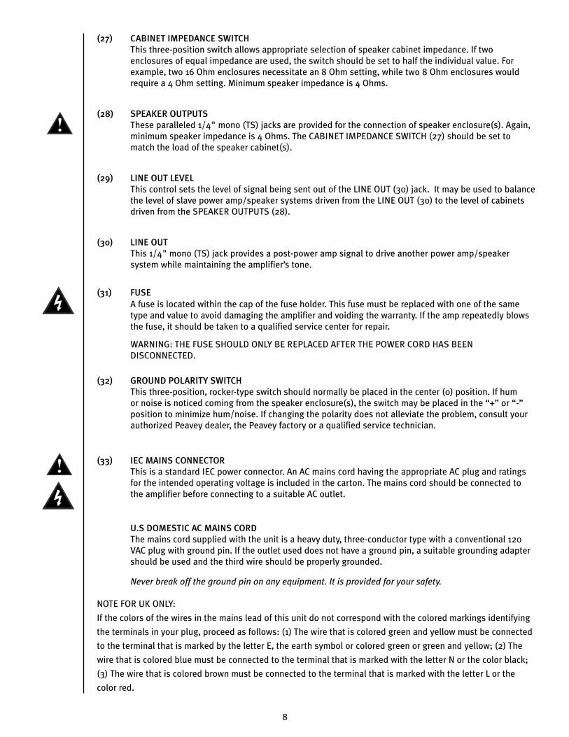
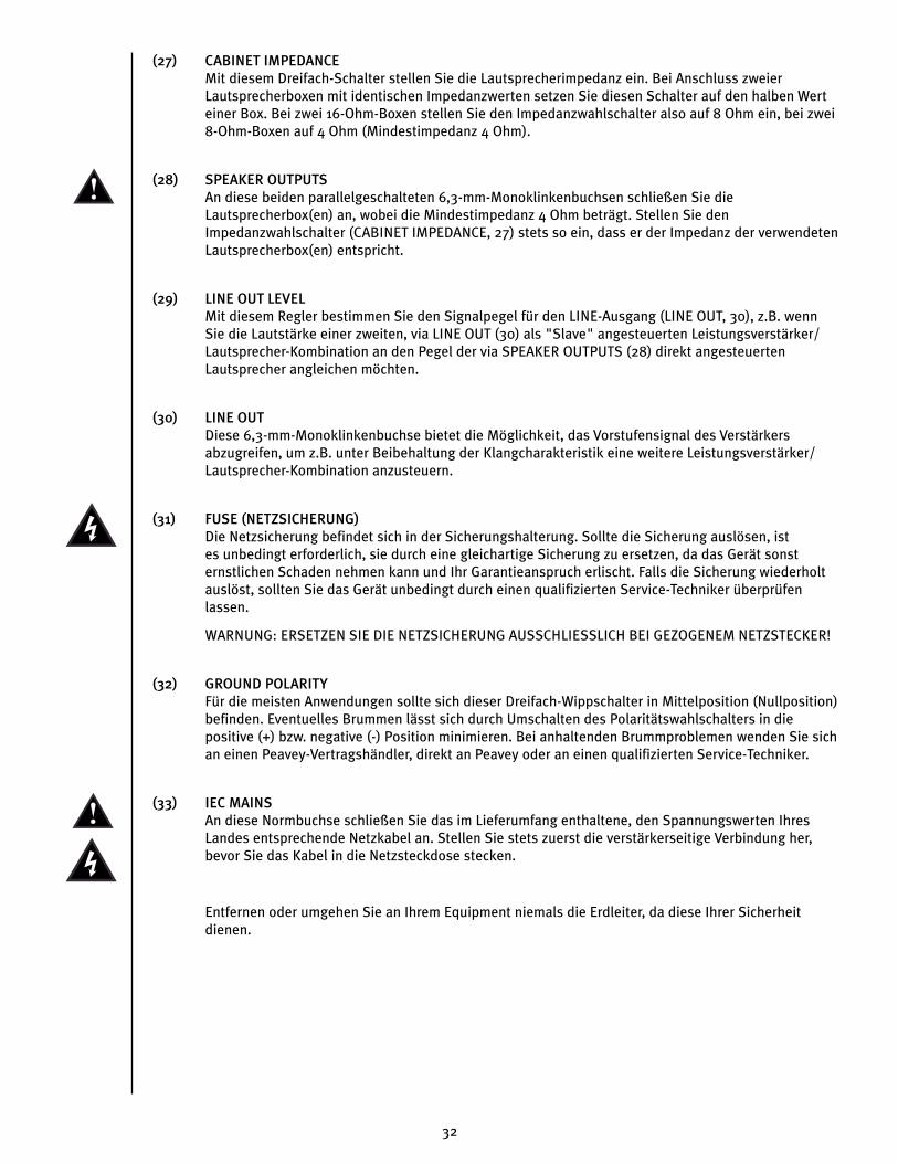
(27) CABINET IMPEDANCE SWITCHThis three-position switch allows appropriate selection of speaker cabinet impedance. If two enclosures of equal impedance are used, the switch should be set to half the individual value. For example, two 16 Ohm enclosures necessitate an 8 Ohm setting, while two 8 Ohm enclosures would require a 4 Ohm setting. Minimum speaker impedance is 4 Ohms.
(28) SPEAKER OUTPUTSThese paralleled 1/4" mono (TS) jacks are provided for the connection of speaker enclosure(s). Again, minimum speaker impedance is 4 Ohms. The CABINET IMPEDANCE SWITCH (27) should be set to match the load of the speaker cabinet(s).
(29) LINE OUT LEVELThis control sets the level of signal being sent out of the LINE OUT (30) jack. It may be used to balance the level of slave power amp/speaker systems driven from the LINE OUT (30) to the level of cabinets driven from the SPEAKER OUTPUTS (28).
(30) LINE OUTThis 1/4" mono (TS) jack provides a post-power amp signal to drive another power amp/speaker system while maintaining the amplifier’s tone.
(31) FUSE A fuse is located within the cap of the fuse holder. This fuse must be replaced with one of the same type and value to avoid damaging the amplifier and voiding the warranty. If the amp repeatedly blows the fuse, it should be taken to a qualified service center for repair.
WARNING: THE FUSE SHOULD ONLY BE REPLACED AFTER THE POWER CORD HAS BEEN DISCONNECTED.
(32) GROUND POLARITY SWITCHThis three-position, rocker-type switch should normally be placed in the center (0) position. If hum or noise is noticed coming from the speaker enclosure(s), the switch may be placed in the “+” or “-” position to minimize hum/noise. If changing the polarity does not alleviate the problem, consult your authorized Peavey dealer, the Peavey factory or a qualified service technician.
(33) IEC MAINS CONNECTORThis is a standard IEC power connector. An AC mains cord having the appropriate AC plug and ratings for the intended operating voltage is included in the carton. The mains cord should be connected to the amplifier before connecting to a suitable AC outlet.
U.S DOMESTIC AC MAINS CORDThe mains cord supplied with the unit is a heavy duty, three-conductor type with a conventional 120 VAC plug with ground pin. If the outlet used does not have a ground pin, a suitable grounding adapter should be used and the third wire should be properly grounded.
Never break off the ground pin on any equipment. It is provided for your safety.
NOTE FOR UK ONLY:
If the colors of the wires in the mains lead of this unit do not correspond with the colored markings identifying
the terminals in your plug, proceed as follows: (1) The wire that is colored green and yellow must be connected
to the terminal that is marked by the letter E, the earth symbol or colored green or green and yellow; (2) The
wire that is colored blue must be connected to the terminal that is marked with the letter N or the color black;
(3) The wire that is colored brown must be connected to the terminal that is marked with the letter L or the
color red.
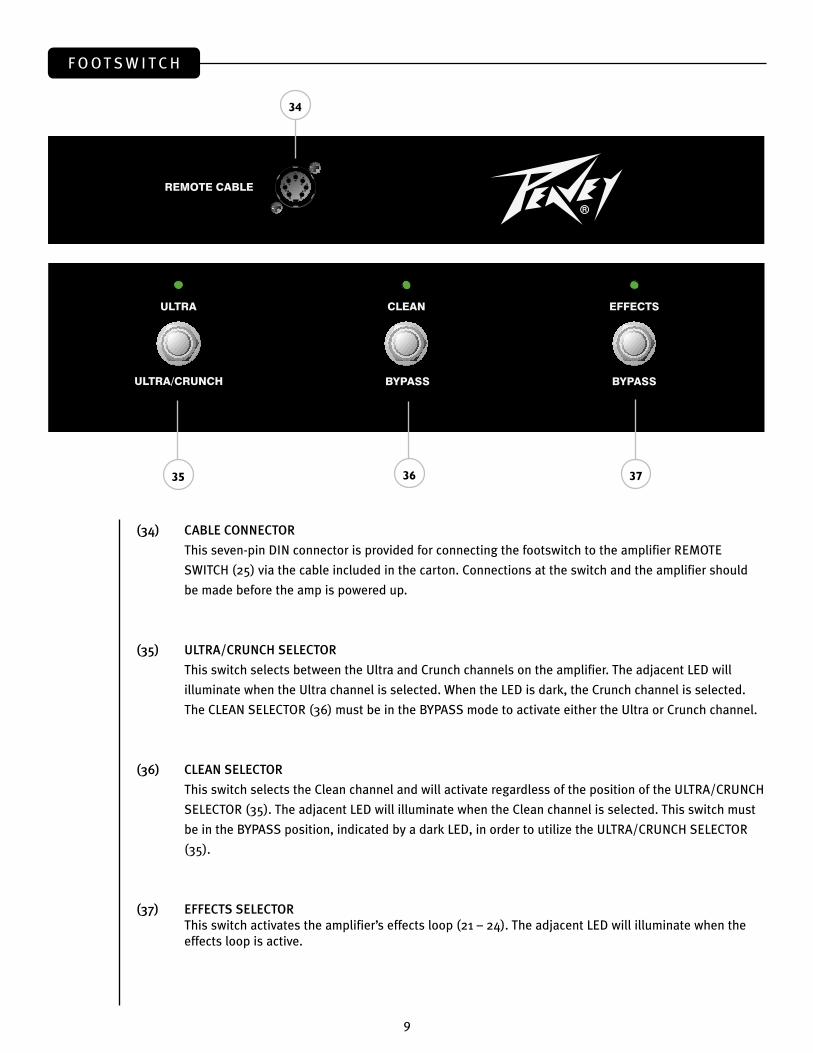
F O O T S W I T C H
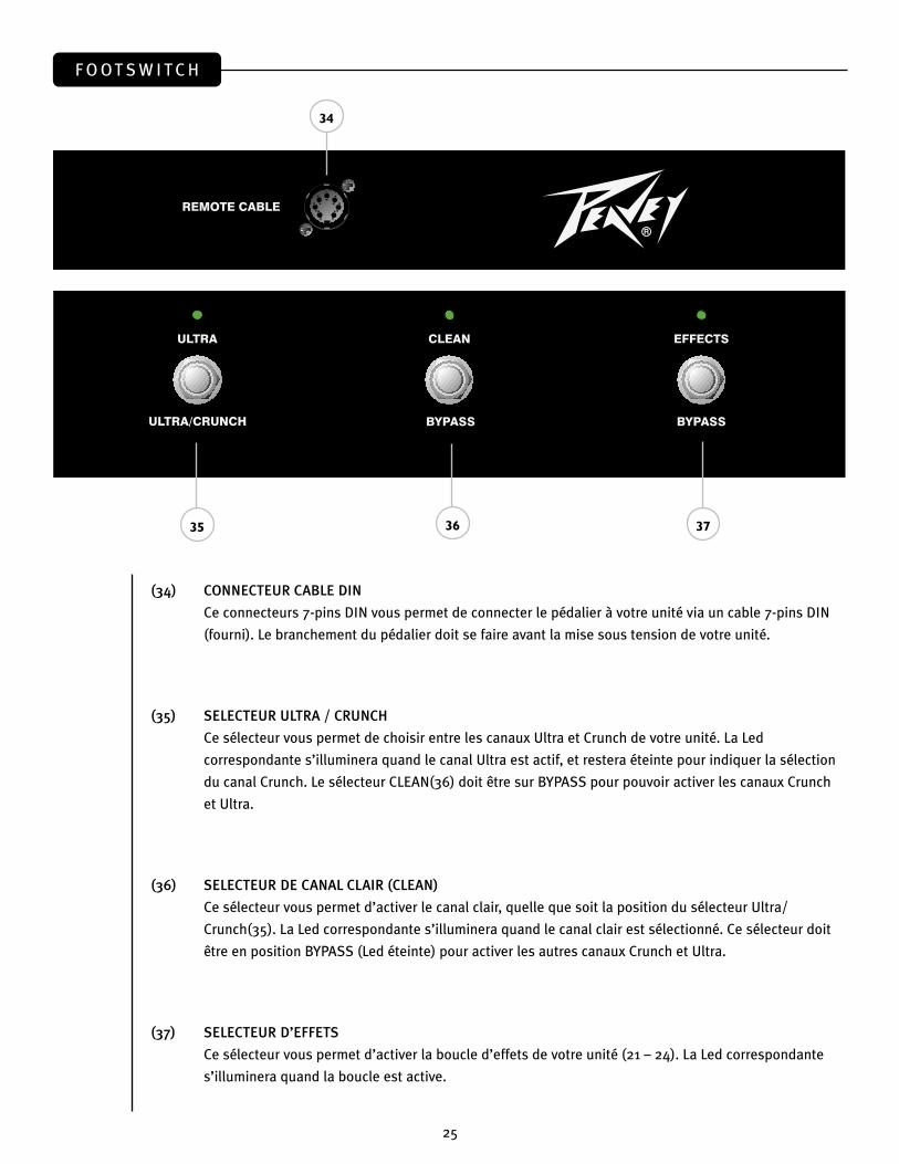
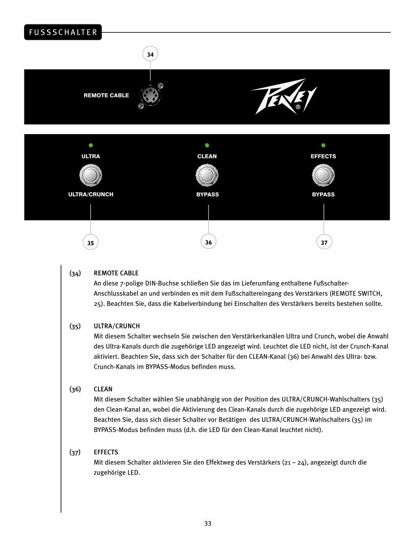
(34) CABLE CONNECTOR
This seven-pin DIN connector is provided for connecting the footswitch to the amplifier REMOTE
SWITCH (25) via the cable included in the carton. Connections at the switch and the amplifier should
be made before the amp is powered up.
(35) ULTRA/CRUNCH SELECTOR
This switch selects between the Ultra and Crunch channels on the amplifier. The adjacent LED will
illuminate when the Ultra channel is selected. When the LED is dark, the Crunch channel is selected.
The CLEAN SELECTOR (36) must be in the BYPASS mode to activate either the Ultra or Crunch channel.
(36) CLEAN SELECTOR
This switch selects the Clean channel and will activate regardless of the position of the ULTRA/CRUNCH
SELECTOR (35). The adjacent LED will illuminate when the Clean channel is selected. This switch must
be in the BYPASS position, indicated by a dark LED, in order to utilize the ULTRA/CRUNCH SELECTOR
(35).
(37) EFFECTS SELECTORThis switch activates the amplifier’s effects loop (21 – 24). The adjacent LED will illuminate when the effects loop is active.
35 37
34
36
8
(27) CABINET IMPEDANCE SWITCHThis three-position switch allows appropriate selection of speaker cabinet impedance. If two enclosures of equal impedance are used, the switch should be set to half the individual value. For example, two 16 Ohm enclosures necessitate an 8 Ohm setting, while two 8 Ohm enclosures would require a 4 Ohm setting. Minimum speaker impedance is 4 Ohms.
(28) SPEAKER OUTPUTSThese paralleled 1/4" mono (TS) jacks are provided for the connection of speaker enclosure(s). Again, minimum speaker impedance is 4 Ohms. The CABINET IMPEDANCE SWITCH (27) should be set to match the load of the speaker cabinet(s).
(29) LINE OUT LEVELThis control sets the level of signal being sent out of the LINE OUT (30) jack. It may be used to balance the level of slave power amp/speaker systems driven from the LINE OUT (30) to the level of cabinets driven from the SPEAKER OUTPUTS (28).
(30) LINE OUTThis 1/4" mono (TS) jack provides a post-power amp signal to drive another power amp/speaker system while maintaining the amplifier’s tone.
(31) FUSE A fuse is located within the cap of the fuse holder. This fuse must be replaced with one of the same type and value to avoid damaging the amplifier and voiding the warranty. If the amp repeatedly blows the fuse, it should be taken to a qualified service center for repair.
WARNING: THE FUSE SHOULD ONLY BE REPLACED AFTER THE POWER CORD HAS BEEN DISCONNECTED.
(32) GROUND POLARITY SWITCHThis three-position, rocker-type switch should normally be placed in the center (0) position. If hum or noise is noticed coming from the speaker enclosure(s), the switch may be placed in the “+” or “-” position to minimize hum/noise. If changing the polarity does not alleviate the problem, consult your authorized Peavey dealer, the Peavey factory or a qualified service technician.
(33) IEC MAINS CONNECTORThis is a standard IEC power connector. An AC mains cord having the appropriate AC plug and ratings for the intended operating voltage is included in the carton. The mains cord should be connected to the amplifier before connecting to a suitable AC outlet.
U.S DOMESTIC AC MAINS CORDThe mains cord supplied with the unit is a heavy duty, three-conductor type with a conventional 120 VAC plug with ground pin. If the outlet used does not have a ground pin, a suitable grounding adapter should be used and the third wire should be properly grounded.
Never break off the ground pin on any equipment. It is provided for your safety.
NOTE FOR UK ONLY:
If the colors of the wires in the mains lead of this unit do not correspond with the colored markings identifying
the terminals in your plug, proceed as follows: (1) The wire that is colored green and yellow must be connected
to the terminal that is marked by the letter E, the earth symbol or colored green or green and yellow; (2) The
wire that is colored blue must be connected to the terminal that is marked with the letter N or the color black;
(3) The wire that is colored brown must be connected to the terminal that is marked with the letter L or the
color red.
F O O T S W I T C H
(34) CABLE CONNECTOR
This seven-pin DIN connector is provided for connecting the footswitch to the amplifier REMOTE
SWITCH (25) via the cable included in the carton. Connections at the switch and the amplifier should
be made before the amp is powered up.
(35) ULTRA/CRUNCH SELECTOR
This switch selects between the Ultra and Crunch channels on the amplifier. The adjacent LED will
illuminate when the Ultra channel is selected. When the LED is dark, the Crunch channel is selected.
The CLEAN SELECTOR (36) must be in the BYPASS mode to activate either the Ultra or Crunch channel.
(36) CLEAN SELECTOR
This switch selects the Clean channel and will activate regardless of the position of the ULTRA/CRUNCH
SELECTOR (35). The adjacent LED will illuminate when the Clean channel is selected. This switch must
be in the BYPASS position, indicated by a dark LED, in order to utilize the ULTRA/CRUNCH SELECTOR
(35).
(37) EFFECTS SELECTORThis switch activates the amplifier’s effects loop (21 – 24). The adjacent LED will illuminate when the effects loop is active.
35 37
34
36
9

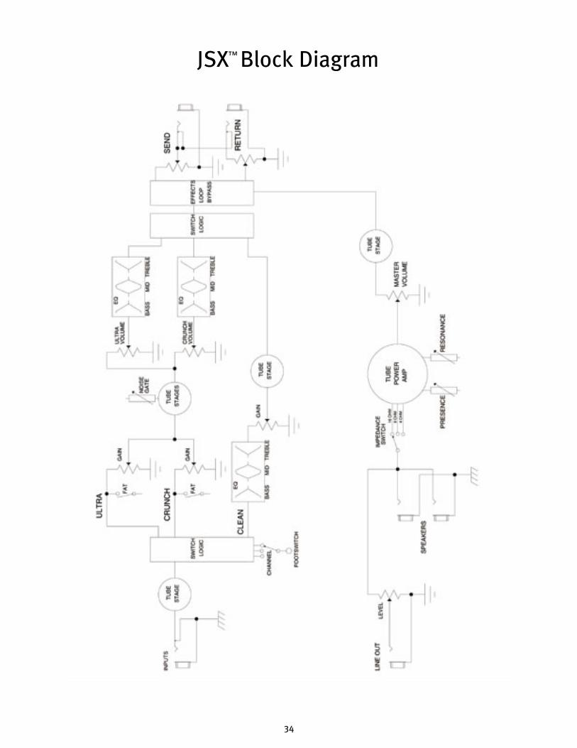
JSXSPECIFICATIONSJSX Block Diagram
Note: For proper ventilation‚ allow 24" clearance from nearest combustible surface.
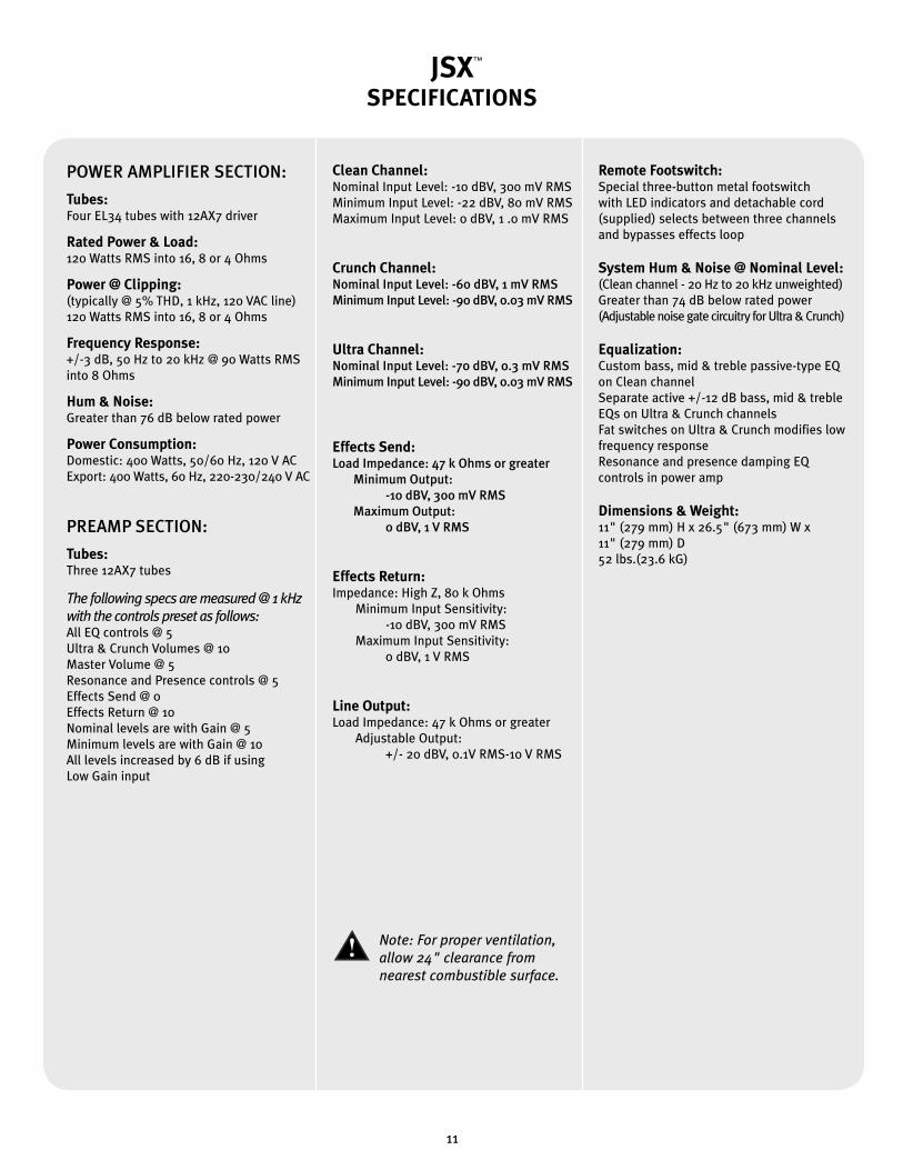
POWER AMPLIFIER SECTION:
Tubes:Four EL34 tubes with 12AX7 driver Rated Power & Load:120 Watts RMS into 16, 8 or 4 Ohms
Power @ Clipping:(typically @ 5% THD, 1 kHz, 120 VAC line)120 Watts RMS into 16, 8 or 4 Ohms
Frequency Response:+/-3 dB, 50 Hz to 20 kHz @ 90 Watts RMS into 8 Ohms
Hum & Noise:Greater than 76 dB below rated power
Power Consumption:Domestic: 400 Watts, 50/60 Hz, 120 V ACExport: 400 Watts, 60 Hz, 220-230/240 V AC
PREAMP SECTION:
Tubes:Three 12AX7 tubes
The following specs are measured @ 1 kHz with the controls preset as follows:All EQ controls @ 5Ultra & Crunch Volumes @ 10Master Volume @ 5Resonance and Presence controls @ 5Effects Send @ 0Effects Return @ 10Nominal levels are with Gain @ 5Minimum levels are with Gain @ 10All levels increased by 6 dB if using Low Gain input
Clean Channel:Nominal Input Level: -10 dBV, 300 mV RMSMinimum Input Level: -22 dBV, 80 mV RMSMaximum Input Level: 0 dBV, 1 .0 mV RMS
Crunch Channel:Nominal Input Level: -60 dBV, 1 mV RMSMinimum Input Level: -90 dBV, 0.03 mV RMS
Ultra Channel:Nominal Input Level: -70 dBV, 0.3 mV RMSMinimum Input Level: -90 dBV, 0.03 mV RMS
Effects Send:Load Impedance: 47 k Ohms or greater Minimum Output: -10 dBV, 300 mV RMS Maximum Output: 0 dBV, 1 V RMS
Effects Return:Impedance: High Z, 80 k Ohms Minimum Input Sensitivity: -10 dBV, 300 mV RMS Maximum Input Sensitivity: 0 dBV, 1 V RMS
Line Output:Load Impedance: 47 k Ohms or greater Adjustable Output: +/- 20 dBV, 0.1V RMS-10 V RMS
Remote Footswitch:Special three-button metal footswitch with LED indicators and detachable cord (supplied) selects between three channels and bypasses effects loop
System Hum & Noise @ Nominal Level:(Clean channel - 20 Hz to 20 kHz unweighted)Greater than 74 dB below rated power(Adjustable noise gate circuitry for Ultra & Crunch)
Equalization: Custom bass, mid & treble passive-type EQ on Clean channelSeparate active +/-12 dB bass, mid & treble EQs on Ultra & Crunch channelsFat switches on Ultra & Crunch modifies low frequency responseResonance and presence damping EQ controls in power amp
Dimensions & Weight:11" (279 mm) H x 26.5" (673 mm) W x 11" (279 mm) D52 lbs.(23.6 kG)
™
™
10
JSXSPECIFICATIONSJSX Block Diagram
Note: For proper ventilation‚ allow 24" clearance from nearest combustible surface.
POWER AMPLIFIER SECTION:
Tubes:Four EL34 tubes with 12AX7 driver Rated Power & Load:120 Watts RMS into 16, 8 or 4 Ohms
Power @ Clipping:(typically @ 5% THD, 1 kHz, 120 VAC line)120 Watts RMS into 16, 8 or 4 Ohms
Frequency Response:+/-3 dB, 50 Hz to 20 kHz @ 90 Watts RMS into 8 Ohms
Hum & Noise:Greater than 76 dB below rated power
Power Consumption:Domestic: 400 Watts, 50/60 Hz, 120 V ACExport: 400 Watts, 60 Hz, 220-230/240 V AC
PREAMP SECTION:
Tubes:Three 12AX7 tubes
The following specs are measured @ 1 kHz with the controls preset as follows:All EQ controls @ 5Ultra & Crunch Volumes @ 10Master Volume @ 5Resonance and Presence controls @ 5Effects Send @ 0Effects Return @ 10Nominal levels are with Gain @ 5Minimum levels are with Gain @ 10All levels increased by 6 dB if using Low Gain input
Clean Channel:Nominal Input Level: -10 dBV, 300 mV RMSMinimum Input Level: -22 dBV, 80 mV RMSMaximum Input Level: 0 dBV, 1 .0 mV RMS
Crunch Channel:Nominal Input Level: -60 dBV, 1 mV RMSMinimum Input Level: -90 dBV, 0.03 mV RMS
Ultra Channel:Nominal Input Level: -70 dBV, 0.3 mV RMSMinimum Input Level: -90 dBV, 0.03 mV RMS
Effects Send:Load Impedance: 47 k Ohms or greater Minimum Output: -10 dBV, 300 mV RMS Maximum Output: 0 dBV, 1 V RMS
Effects Return:Impedance: High Z, 80 k Ohms Minimum Input Sensitivity: -10 dBV, 300 mV RMS Maximum Input Sensitivity: 0 dBV, 1 V RMS
Line Output:Load Impedance: 47 k Ohms or greater Adjustable Output: +/- 20 dBV, 0.1V RMS-10 V RMS
Remote Footswitch:Special three-button metal footswitch with LED indicators and detachable cord (supplied) selects between three channels and bypasses effects loop
System Hum & Noise @ Nominal Level:(Clean channel - 20 Hz to 20 kHz unweighted)Greater than 74 dB below rated power(Adjustable noise gate circuitry for Ultra & Crunch)
Equalization: Custom bass, mid & treble passive-type EQ on Clean channelSeparate active +/-12 dB bass, mid & treble EQs on Ultra & Crunch channelsFat switches on Ultra & Crunch modifies low frequency responseResonance and presence damping EQ controls in power amp
Dimensions & Weight:11" (279 mm) H x 26.5" (673 mm) W x 11" (279 mm) D52 lbs.(23.6 kG)
™
™
11

Felicitaciones en la compra de su amplificador para guitarra Peavey
JSX. El JSX es para el guitarrista su sueño hecho realidad – el
amplificador que le impartirá tanto a su sonido como a cualquiera
que sea su estilo de ejecución, una calidad superior. Sólo los
materiales más finos se han utilizado en crear esta máquina tonal
de gran sonido, resistente, digna de giras, y con una apariencia
única. ¡Espero que este amp le guste tanto como a mí!
ESPAÑOL
Características
• Tres Válvulas de preamplificador 12AX7
• Cuatro válvulas de amplificador EL34 alimentados por un 12AX7
• Amplificador convertible para usar válvulas 6L6GC
• Circuito de efectos controlable por pedal con controles independientes de envió y retorno
• Resonancia y controles de amortiguación de presencia.
• Circuito de portón de ruido en canales Ultra y Crunch completamente ajustables.
• Salida de línea con control de nivel
• interruptor de impedancia de gabinetes (4, 8, o 16 Ohmios)
• Interruptores resistentes de encendido standby y canal
• Lámpara clásica indicadora de estatus
Joe Satriani
™
12
PA N E L F R O N TA L
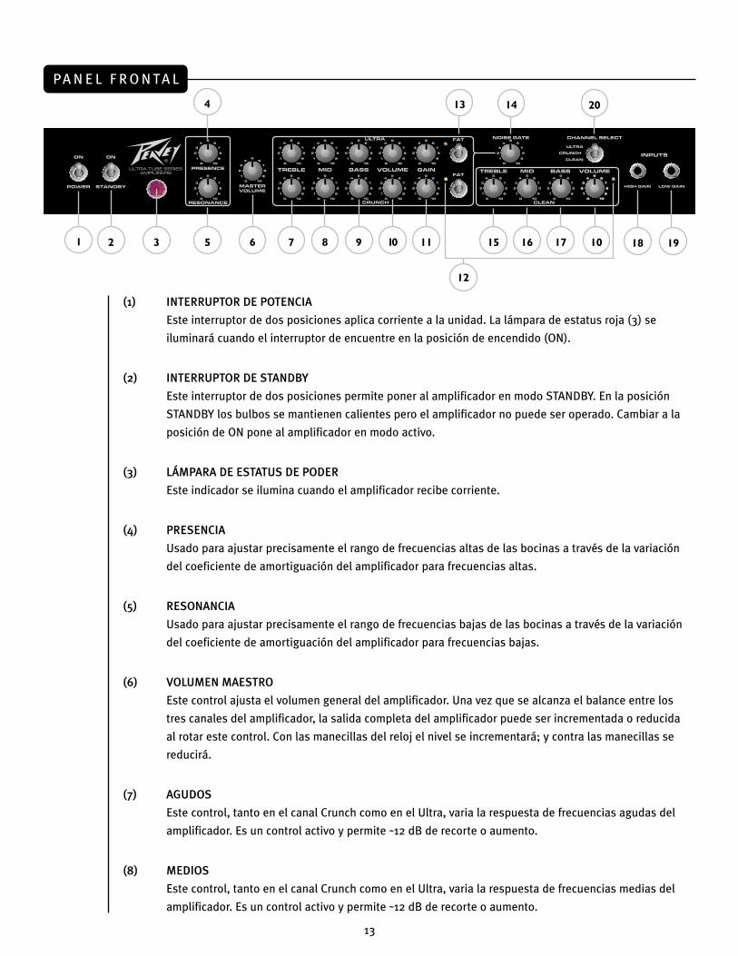
(1) INTERRUPTOR DE POTENCIA
Este interruptor de dos posiciones aplica corriente a la unidad. La lámpara de estatus roja (3) se
iluminará cuando el interruptor de encuentre en la posición de encendido (ON).
(2) INTERRUPTOR DE STANDBY
Este interruptor de dos posiciones permite poner al amplificador en modo STANDBY. En la posición
STANDBY los bulbos se mantienen calientes pero el amplificador no puede ser operado. Cambiar a la
posición de ON pone al amplificador en modo activo.
(3) LÁMPARA DE ESTATUS DE PODER
Este indicador se ilumina cuando el amplificador recibe corriente.
(4) PRESENCIA
Usado para ajustar precisamente el rango de frecuencias altas de las bocinas a través de la variación
del coeficiente de amortiguación del amplificador para frecuencias altas.
(5) RESONANCIA
Usado para ajustar precisamente el rango de frecuencias bajas de las bocinas a través de la variación
del coeficiente de amortiguación del amplificador para frecuencias bajas.
(6) VOLUMEN MAESTRO
Este control ajusta el volumen general del amplificador. Una vez que se alcanza el balance entre los
tres canales del amplificador, la salida completa del amplificador puede ser incrementada o reducida
al rotar este control. Con las manecillas del reloj el nivel se incrementará; y contra las manecillas se
reducirá.
(7) AGUDOS
Este control, tanto en el canal Crunch como en el Ultra, varia la respuesta de frecuencias agudas del
amplificador. Es un control activo y permite ˜12 dB de recorte o aumento.
(8) MEDIOS
Este control, tanto en el canal Crunch como en el Ultra, varia la respuesta de frecuencias medias del
amplificador. Es un control activo y permite ˜12 dB de recorte o aumento.
1 3 5 7 9 11
13
152
4
6 8 10
14
16 10
12
19
20
17 18
13
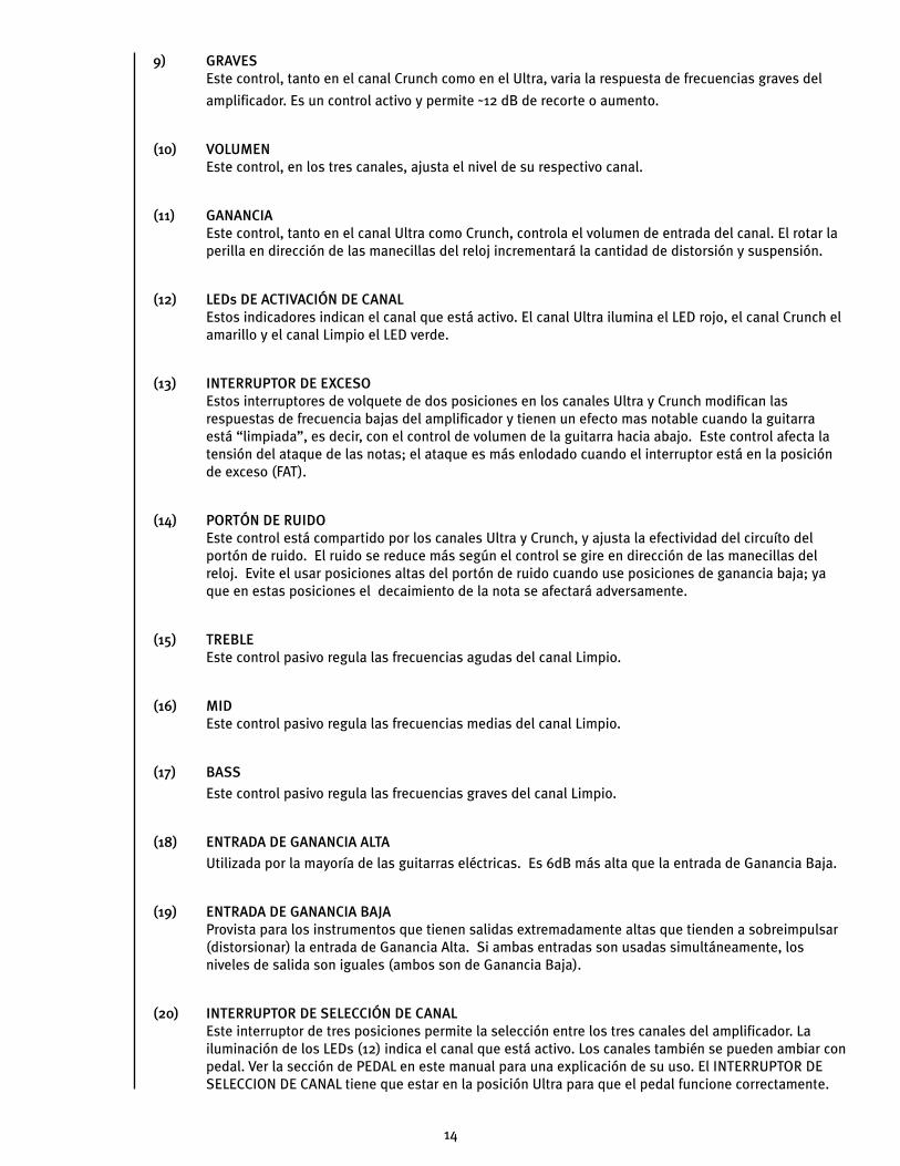
9) GRAVESEste control, tanto en el canal Crunch como en el Ultra, varia la respuesta de frecuencias graves del
amplificador. Es un control activo y permite ˜12 dB de recorte o aumento.
(10) VOLUMENEste control, en los tres canales, ajusta el nivel de su respectivo canal.
(11) GANANCIAEste control, tanto en el canal Ultra como Crunch, controla el volumen de entrada del canal. El rotar la perilla en dirección de las manecillas del reloj incrementará la cantidad de distorsión y suspensión.
(12) LEDs DE ACTIVACIÓN DE CANALEstos indicadores indican el canal que está activo. El canal Ultra ilumina el LED rojo, el canal Crunch el amarillo y el canal Limpio el LED verde.
(13) INTERRUPTOR DE EXCESOEstos interruptores de volquete de dos posiciones en los canales Ultra y Crunch modifican las respuestas de frecuencia bajas del amplificador y tienen un efecto mas notable cuando la guitarra está “limpiada”, es decir, con el control de volumen de la guitarra hacia abajo. Este control afecta la tensión del ataque de las notas; el ataque es más enlodado cuando el interruptor está en la posición de exceso (FAT).
(14) PORTÓN DE RUIDOEste control está compartido por los canales Ultra y Crunch, y ajusta la efectividad del circuíto del portón de ruido. El ruido se reduce más según el control se gire en dirección de las manecillas del reloj. Evite el usar posiciones altas del portón de ruido cuando use posiciones de ganancia baja; ya que en estas posiciones el decaimiento de la nota se afectará adversamente.
(15) TREBLEEste control pasivo regula las frecuencias agudas del canal Limpio.
(16) MIDEste control pasivo regula las frecuencias medias del canal Limpio.
(17) BASS
Este control pasivo regula las frecuencias graves del canal Limpio.
(18) ENTRADA DE GANANCIA ALTA
Utilizada por la mayoría de las guitarras eléctricas. Es 6dB más alta que la entrada de Ganancia Baja.
(19) ENTRADA DE GANANCIA BAJAProvista para los instrumentos que tienen salidas extremadamente altas que tienden a sobreimpulsar (distorsionar) la entrada de Ganancia Alta. Si ambas entradas son usadas simultáneamente, los niveles de salida son iguales (ambos son de Ganancia Baja).
(20) INTERRUPTOR DE SELECCIÓN DE CANALEste interruptor de tres posiciones permite la selección entre los tres canales del amplificador. La iluminación de los LEDs (12) indica el canal que está activo. Los canales también se pueden ambiar con pedal. Ver la sección de PEDAL en este manual para una explicación de su uso. El INTERRUPTOR DE SELECCION DE CANAL tiene que estar en la posición Ultra para que el pedal funcione correctamente.
14
PA N E L T R A S E R O
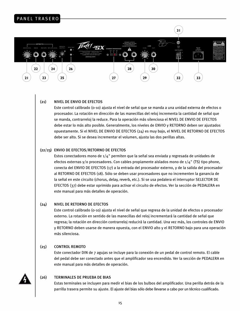
(21) NIVEL DE ENVIO DE EFECTOS
Este control calibrado (0-10) ajusta el nivel de señal que se manda a una unidad externa de efectos o
procesador. La rotación en dirección de las manecillas del reloj incrementa la cantidad de señal que
se manda, contrarreloj la reduce. Para la operación más silenciosa el NIVEL DE ENVIO DE EFECTOS
debe estar lo más alto posible. Generalmente, los niveles de ENVIO y RETORNO deben ser ajustados
opuestamente. Si el NIVEL DE ENVIO DE EFECTOS (24) es muy bajo, el NIVEL DE RETORNO DE EFECTOS
debe ser alto. Si se desea incrementar el volumen, ajusta las dos perillas altas.
(22/23) ENVIO DE EFECTOS/RETORNO DE EFECTOS
Estos conectadores mono de 1/4" permiten que la señal sea enviada y regresada de unidades de
efectos externas y/o procesadores. Con cables propiamente aislados mono de 1/4" (TS) tipo phone,
conecta del ENVIO DE EFECTOS (17) a la entrada del procesador externo, y de la salida del procesador
al RETORNO DE EFECTOS (18). Sólo se deben usar procesadores que no incrementen la ganancia de
la señal en este circuito (chorus, delay, reverb, etc.). Si se usa pedalera el interruptor SELECTOR DE
EFECTOS (37) debe estar oprimido para activar el circuito de efectos. Ver la sección de PEDALERA en
este manual para más detalles de operación.
(24) NIVEL DE RETORNO DE EFECTOS
Este control calibrado (0-10) ajusta el nivel de señal que regresa de la unidad de efectos o procesador
externo. La rotación en sentido de las manecillas del reloj incrementará la cantidad de señal que
regresa; la rotación en dirección contrarreloj reducirá la cantidad. Una vez más, los controles de ENVIO
y RETORNO deben usarse de manera opuesta, con el ENVIO alto y el RETORNO bajo para una operación
más silenciosa.
(25) CONTROL REMOTO
Este conectador DIN de 7 agujas se incluye para la conexión de un pedal de control remoto. El cable
del pedal debe ser conectado antes que el amplificador sea encendido. Ver la sección de PEDALERA en
este manual para más detalles de operación.
(26) TERMINALES DE PRUEBA DE BIAS
Estas terminales se incluyen para medir el bias de los bulbos del amplificador. Una perilla detrás de la
parrilla trasera permite su ajuste. El ajuste del bias sólo debe llevarse a cabo por un técnico cualificado.
22 24 26
21 25 27 2923
28 30
32
31
33
15
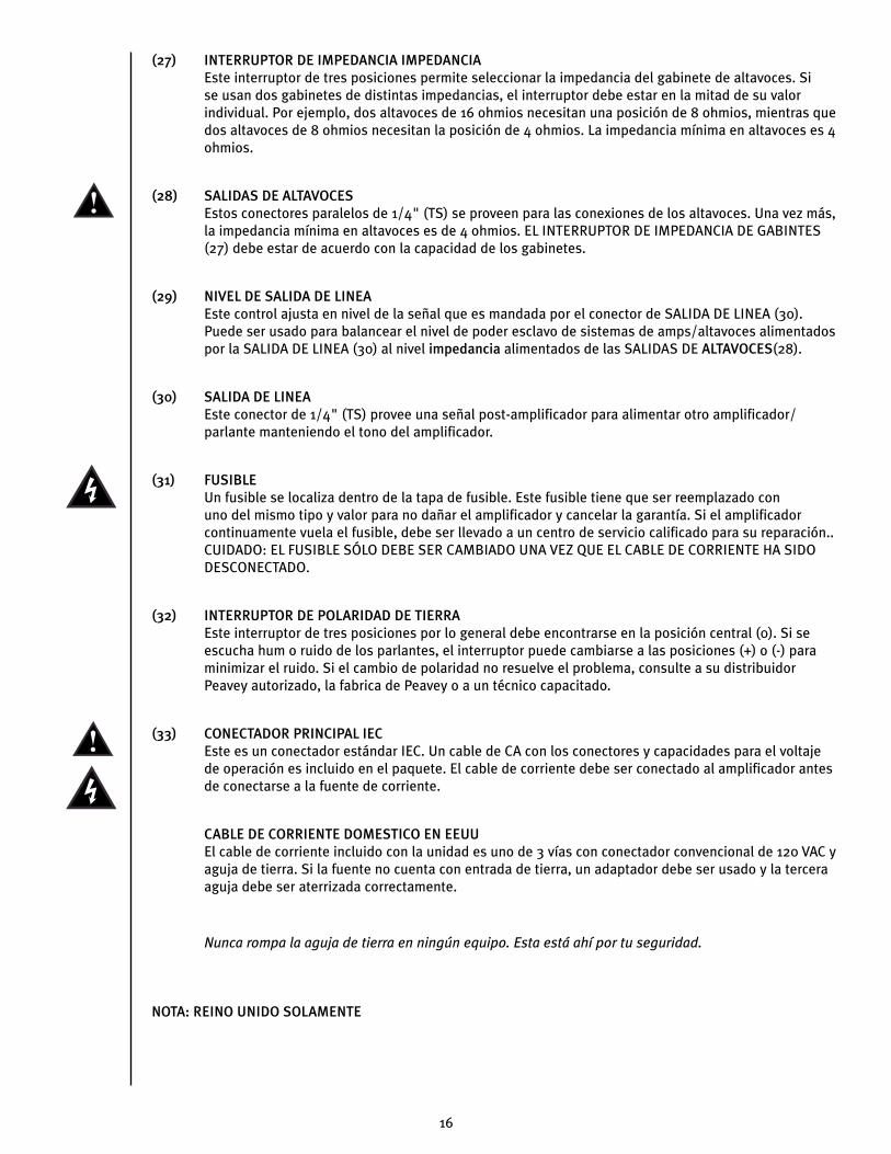
(27) INTERRUPTOR DE IMPEDANCIA IMPEDANCIAEste interruptor de tres posiciones permite seleccionar la impedancia del gabinete de altavoces. Si se usan dos gabinetes de distintas impedancias, el interruptor debe estar en la mitad de su valor individual. Por ejemplo, dos altavoces de 16 ohmios necesitan una posición de 8 ohmios, mientras que dos altavoces de 8 ohmios necesitan la posición de 4 ohmios. La impedancia mínima en altavoces es 4 ohmios.
(28) SALIDAS DE ALTAVOCESEstos conectores paralelos de 1/4" (TS) se proveen para las conexiones de los altavoces. Una vez más, la impedancia mínima en altavoces es de 4 ohmios. EL INTERRUPTOR DE IMPEDANCIA DE GABINTES (27) debe estar de acuerdo con la capacidad de los gabinetes.
(29) NIVEL DE SALIDA DE LINEAEste control ajusta en nivel de la señal que es mandada por el conector de SALIDA DE LINEA (30). Puede ser usado para balancear el nivel de poder esclavo de sistemas de amps/altavoces alimentados por la SALIDA DE LINEA (30) al nivel impedancia alimentados de las SALIDAS DE ALTAVOCES(28).
(30) SALIDA DE LINEAEste conector de 1/4" (TS) provee una señal post-amplificador para alimentar otro amplificador/parlante manteniendo el tono del amplificador.
(31) FUSIBLEUn fusible se localiza dentro de la tapa de fusible. Este fusible tiene que ser reemplazado con uno del mismo tipo y valor para no dañar el amplificador y cancelar la garantía. Si el amplificador continuamente vuela el fusible, debe ser llevado a un centro de servicio calificado para su reparación.. CUIDADO: EL FUSIBLE SÓLO DEBE SER CAMBIADO UNA VEZ QUE EL CABLE DE CORRIENTE HA SIDO DESCONECTADO.
(32) INTERRUPTOR DE POLARIDAD DE TIERRAEste interruptor de tres posiciones por lo general debe encontrarse en la posición central (0). Si se escucha hum o ruido de los parlantes, el interruptor puede cambiarse a las posiciones (+) o (-) para minimizar el ruido. Si el cambio de polaridad no resuelve el problema, consulte a su distribuidor Peavey autorizado, la fabrica de Peavey o a un técnico capacitado.
(33) CONECTADOR PRINCIPAL IECEste es un conectador estándar IEC. Un cable de CA con los conectores y capacidades para el voltaje de operación es incluido en el paquete. El cable de corriente debe ser conectado al amplificador antes de conectarse a la fuente de corriente.
CABLE DE CORRIENTE DOMESTICO EN EEUUEl cable de corriente incluido con la unidad es uno de 3 vías con conectador convencional de 120 VAC y aguja de tierra. Si la fuente no cuenta con entrada de tierra, un adaptador debe ser usado y la tercera aguja debe ser aterrizada correctamente.
Nunca rompa la aguja de tierra en ningún equipo. Esta está ahí por tu seguridad.
NOTA: REINO UNIDO SOLAMENTE
16
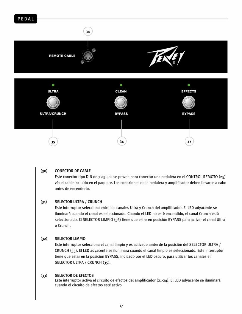
P E D A L
(30) CONECTOR DE CABLE
Este conector tipo DIN de 7 agujas se provee para conectar una pedalera en el CONTROL REMOTO (25)
vía el cable incluido en el paquete. Las conexiones de la pedalera y amplificador deben llevarse a cabo
antes de encenderlo.
(31) SELECTOR ULTRA / CRUNCH
Este interruptor selecciona entre los canales Ultra y Crunch del amplificador. El LED adyacente se
iluminará cuando el canal es seleccionado. Cuando el LED no esté encendido, el canal Crunch está
seleccionado. El SELECTOR LIMPIO (36) tiene que estar en posición BYPASS para activar el canal Ultra
o Crunch.
(32) SELECTOR LIMPIO
Este interruptor selecciona el canal limpio y es activado amén de la posición del SELECTOR ULTRA /
CRUNCH (35). El LED adyacente se iluminará cuando el canal limpio es seleccionado. Este interruptor
tiene que estar en la posición BYPASS, indicado por el LED oscuro, para utilizar los canales el
SELECTOR ULTRA / CRUNCH (35).
(33) SELECTOR DE EFECTOSEste interruptor activa el circuito de efectos del amplificador (21-24). El LED adyacente se iluminará cuando el circuito de efectos esté activo
35 37
34
36
17
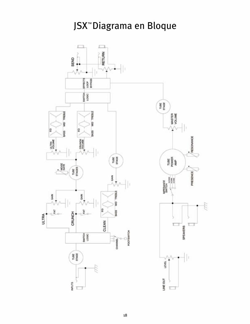
JSX Diagrama en Bloque™
18
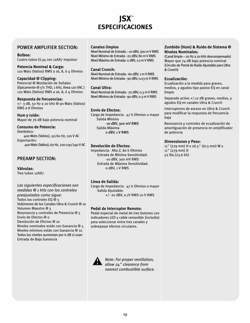
JSXESPECIFICACIONES
Note: For proper ventilation‚ allow 24" clearance from nearest combustible surface.
POWER AMPLIFIER SECTION:
Bulbos:Cuatro tubos EL34 con 12AX7 impulsor Potencia Nominal & Carga:120 Wats (Vatios) RMS a 16, 8, ó 4 Ohmios
Capacidad @ Clipping:Potencial @ Mutilación de Señales(típicamente @ 5% THD, 1 kHz, línea 120 VAC )120 Wats (Vatios) RMS a 16, 8, ó 4 Ohmios
Respuesta de frecuencias:+/- 3 dB, 50 Hz a 20 kHz @ 90 Wats (Vatios) RMS a 8 Ohmios
Hum y ruido:Mayor de 76 dB bajo potencia nominal
Consumo de Potencia:Doméstico: 400 Wats (Vatios), 50/60 Hz, 120 V ACExportación: 400 Wats (Vatios), 60 Hz, 220-230/240 V AC
PREAMP SECTION:
Válvulas:Tres tubos 12AX7
Las siguientes especificaciones son medidas @ 1 kHz con los controles preajustados como sigue:Todos los controles EQ @ 5Volúmenes de los Canales Ultra & Crunch @ 10Volumen Maestro @ 5Resonancia y controles de Presencia @ 5Envío de Efectos @ 0Devolución de Efectos @ 10Niveles nominales están con Ganancia @ 5Niveles mínimos están con Ganancia @ 10Todos los niveles aumentan por 6 dB si usanEntrada de Baja Ganancia
Canales limpiosNivel Nominal de Entrada : -10 dBV, 300 m V RMSNivel Mínimo de Entrada: -22 dBV, 80 m V RMSNivel Máximo de Entrada: 0 dBV, 1.0 m V RMS
Canal Crunch:Nivel Nominal de Entrada: -60 dBV, 1 m V RMSNivel Mínimo de Entrada: -90 dBV, 0.03 m V RMS
Canal Ultra:Nivel Nominal de Entrada: -70 dBV, 0.3 m V RMSNivel Mínimo de Entrada: -90 dBV, 0.3 m V RMS
Envío de Efectos:Carga de Impedancia: 47 k Ohmios o mayor Salida Mínima -10 dBV, 300 mV RMS Salida Máxima 0 dBV, 1 V RMS
Devolución de Efectos:Impedancia: Alta Z, 80 k Ohmios Entrada de Mínima Sensitividad: -10 dBV, 300 mV RMS Entrada de Máxima Sensitividad: 0 dBV, 1 V RMS
Línea de Salida:Carga de Impedancia: 47 k Ohmios o mayor Salida Ajustable: +/- 20 dBV, 0.1V RMS-10 V RMS
Pedal de Interruptor Remoto:Pedal especial de metal de tres botones con indicadores LED y cable removible (incluído) para seleccionar entre tres canales y sobrepasar efectos circulares.
Zumbido (Hum) & Ruido de Sistema @ Niveles Nominales:(Canal limpio – 20 Hz a 20 kHz descompensado)Mayor que 74 dB bajo potencia nominal(Circuito de Portal de Ruido Ajustable para Ultra & Crunch)
Ecualización:Ecualización a la medida para graves, medios, y agudos tipo pasivo EQ en canal limpio Separado activo +/-12 dB graves, medios, y agudos EQ en canales Ultra & Crunch Interruptores de exceso en Ultra & Crunch para modificar la respuesta de frecuencia baja Resonancia y controles de ecualización de amortiguación de presencia en amplificador de potencia
Dimensiones y Peso:11" (279 mm) H x 26.5" (673 mm) W x 11" (279 mm) D52 lbs.(23.6 kG)
™
19
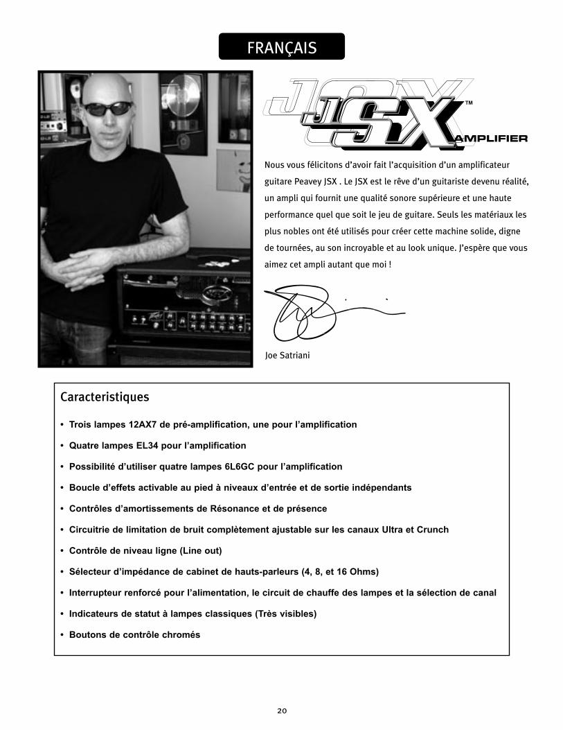
Nous vous félicitons d’avoir fait l’acquisition d’un amplificateur
guitare Peavey JSX . Le JSX est le rêve d’un guitariste devenu réalité,
un ampli qui fournit une qualité sonore supérieure et une haute
performance quel que soit le jeu de guitare. Seuls les matériaux les
plus nobles ont été utilisés pour créer cette machine solide, digne
de tournées, au son incroyable et au look unique. J’espère que vous
aimez cet ampli autant que moi !
FRANÇAIS
Caracteristiques
• Trois lampes 12AX7 de pré-amplification, une pour l’amplification
• Quatre lampes EL34 pour l’amplification
• Possibilité d’utiliser quatre lampes 6L6GC pour l’amplification
• Boucle d’effets activable au pied à niveaux d’entrée et de sortie indépendants
• Contrôles d’amortissements de Résonance et de présence
• Circuitrie de limitation de bruit complètement ajustable sur les canaux Ultra et Crunch
• Contrôle de niveau ligne (Line out)
• Sélecteur d’impédance de cabinet de hauts-parleurs (4, 8, et 16 Ohms)
• Interrupteur renforcé pour l’alimentation, le circuit de chauffe des lampes et la sélection de canal
• Indicateurs de statut à lampes classiques (Très visibles)
• Boutons de contrôle chromés
Joe Satriani
™
20
F R O N T PA N E L
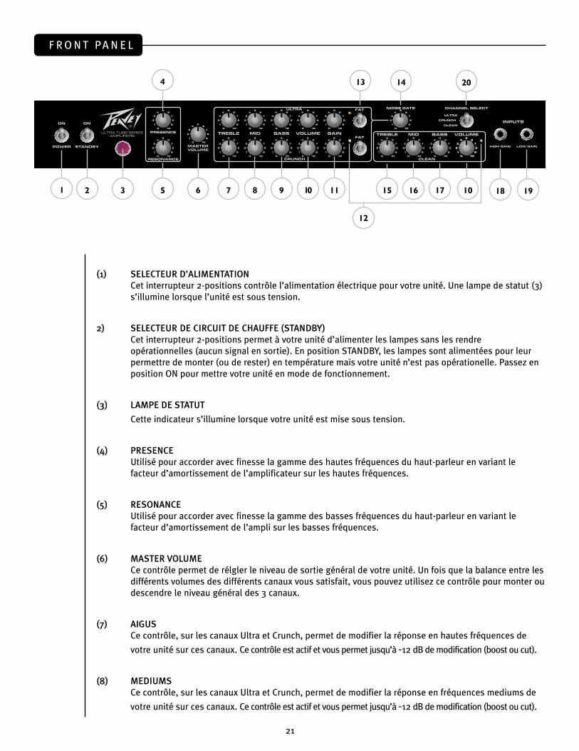
(1) SELECTEUR D’ALIMENTATIONCet interrupteur 2-positions contrôle l’alimentation électrique pour votre unité. Une lampe de statut (3) s’illumine lorsque l’unité est sous tension.
2) SELECTEUR DE CIRCUIT DE CHAUFFE (STANDBY)Cet interrupteur 2-positions permet à votre unité d’alimenter les lampes sans les rendre opérationnelles (aucun signal en sortie). En position STANDBY, les lampes sont alimentées pour leur permettre de monter (ou de rester) en température mais votre unité n’est pas opérationelle. Passez en position ON pour mettre votre unité en mode de fonctionnement.
(3) LAMPE DE STATUT
Cette indicateur s’illumine lorsque votre unité est mise sous tension.
(4) PRESENCEUtilisé pour accorder avec finesse la gamme des hautes fréquences du haut-parleur en variant le facteur d’amortissement de l’amplificateur sur les hautes fréquences.
(5) RESONANCEUtilisé pour accorder avec finesse la gamme des basses fréquences du haut-parleur en variant le facteur d’amortissement de l’ampli sur les basses fréquences.
(6) MASTER VOLUMECe contrôle permet de rélgler le niveau de sortie général de votre unité. Un fois que la balance entre les différents volumes des différents canaux vous satisfait, vous pouvez utilisez ce contrôle pour monter ou descendre le niveau général des 3 canaux.
(7) AIGUSCe contrôle, sur les canaux Ultra et Crunch, permet de modifier la réponse en hautes fréquences de
votre unité sur ces canaux. Ce contrôle est actif et vous permet jusqu’à ˜12 dB de modification (boost ou cut).
(8) MEDIUMS Ce contrôle, sur les canaux Ultra et Crunch, permet de modifier la réponse en fréquences mediums de
votre unité sur ces canaux. Ce contrôle est actif et vous permet jusqu’à ˜12 dB de modification (boost ou cut).
1 3 5 7 9 11
13
152
4
6 8 10
14
16 10
12
19
20
17 18
21
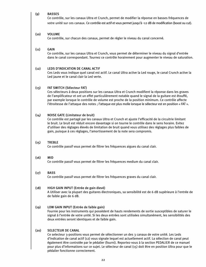
(9) BASSES Ce contrôle, sur les canaux Ultra et Crunch, permet de modifier la réponse en basses fréquences de
votre unité sur ces canaux. Ce contrôle est actif et vous permet jusqu’à ˜12 dB de modification (boost ou cut).
(10) VOLUMECe contrôle, sur chacun des canaux, permet de régler le niveau du canal concerné.
(11) GAINCe contrôle, sur les canaux Ultra et Crunch, vous permet de déterminer le niveau du signal d’entrée dans le canal correspondant. Tournez ce contrôle horairement pour augmenter le niveau de saturation.
(12) LEDS D’INDICATION DE CANAL ACTIFCes Leds vous indique quel canal est actif. Le canal Ultra active la Led rouge, le canal Crunch active la Led jaune et le canal clair la Led verte.
(13) FAT SWITCH (Sélecteur FAT)Ces sélecteurs à deux positions sur les canaux Ultra et Crunch modifient la réponse dans les graves de l’amplificateur et ont un effet particulièrement notable quand le signal de la guitare est étouffé, par exemple lorsque le contrôle de volume est proche de la position minimum. Ce contrôle affecte l’étroitesse de l’attaque des notes ; l’attaque est plus molle lorsque le sélecteur est en position « FAT ».
(14) NOISE GATE (Limitateur de bruit)Ce contrôle est partagé par les canaux Ultra et Crunch et ajuste l’efficacité de la circuitrie limitant le bruit. Le bruit est réduit encore davantage si on tourne le contrôle dans le sens horaire. Evitez d’utiliser des réglages élevés de limitation de bruit quand vous utilisez des réglages plus faibles de gain, puisque à ces réglages, l’amortissement de la note sera compromis.
(15) TREBLECe contrôle passif vous permet de filtrer les fréquences aigues du canal clair.
(16) MIDCe contrôle passif vous permet de filtrer les fréquences medium du canal clair.
(17) BASSCe contrôle passif vous permet de filtrer les fréquences graves du canal clair.
(18) HIGH GAIN INPUT (Entrée de gain élevé)A Utiliser avec la plupart des guitares électroniques, sa sensibilité est de 6 dB supérieure à l’entrée de de faible gain de 6 dB.
(19) LOW GAIN INPUT (Entrée de faible gain)Fournie pour les instruments qui possèdent de hauts rendements de sortie susceptibles de saturer le signal à l’entrée de votre unité. Si les deux entrées sont utilisées simultanément, les sensibilités des deux entrées seront identiques et de faible gain.
(20) SELECTEUR DE CANALCe selecteur 3-positions vous permet de sélectionner un des 3 canaux de votre unité. Les Leds d’indication de canal actif (12) vous signale lequel est actuellement actif. La sélection de canal peut également être controlée par le pédalier (fourni). Reportez-vous à la section PEDALIER de ce manuel pour plus d’informations sur ce sujet. Le sélecteur de canal (15) doit être en position Ultra pour que le pédalier fonctionne correctement.
22
R E A R PA N E L
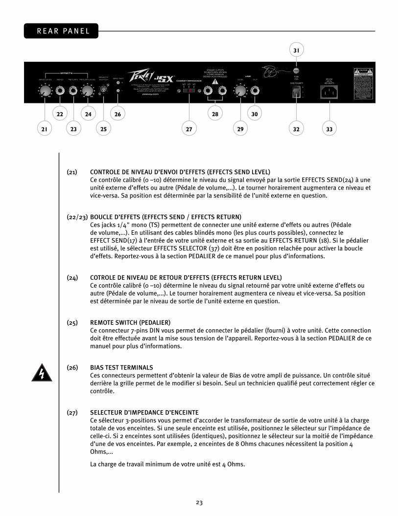
(21) CONTROLE DE NIVEAU D’ENVOI D’EFFETS (EFFECTS SEND LEVEL)Ce contrôle calibré (0 –10) détermine le niveau du signal envoyé par la sortie EFFECTS SEND(24) à une unité externe d’effets ou autre (Pédale de volume,...). Le tourner horairement augmentera ce niveau et vice-versa. Sa position est déterminée par la sensibilité de l’unité externe en question.
(22/23) BOUCLE D’EFFETS (EFFECTS SEND / EFFECTS RETURN) Ces jacks 1/4" mono (TS) permettent de connecter une unité externe d’effets ou autres (Pédale de volume,...). En utilisant des cables blindés mono (les plus courts possibles), connectez le EFFECT SEND(17) à l’entrée de votre unité externe et sa sortie au EFFECTS RETURN (18). Si le pédalier est utilisé, le sélecteur EFFECTS SELECTOR (37) doit être en position relachée pour activer la boucle d’effets. Reportez-vous à la section PEDALIER de ce manuel pour plus d’informations.
(24) COTROLE DE NIVEAU DE RETOUR D’EFFETS (EFFECTS RETURN LEVEL)Ce contrôle calibré (0 –10) détermine le niveau du signal retourné par votre unité externe d’effets ou autre (Pédale de volume,...). Le tourner horairement augmentera ce niveau et vice-versa. Sa position est déterminée par le niveau de sortie de l’unité externe en question.
(25) REMOTE SWITCH (PEDALIER)Ce connecteur 7-pins DIN vous permet de connecter le pédalier (fourni) à votre unité. Cette connection doit être effectuée avant la mise sous tension de l’appareil. Reportez-vous à la section PEDALIER de ce manuel pour plus d’informations.
(26) BIAS TEST TERMINALSCes connecteurs permettent d’obtenir la valeur de Bias de votre ampli de puissance. Un contrôle situé derrière la grille permet de le modifier si besoin. Seul un technicien qualifié peut correctement régler ce contrôle.
(27) SELECTEUR D’IMPEDANCE D’ENCEINTECe sélecteur 3-positions vous permet d’accorder le transformateur de sortie de votre unité à la charge totale de vos enceintes. Si une seule enceinte est utilisée, positionnez le sélecteur sur l’impédance de celle-ci. Si 2 enceintes sont utilisées (identiques), positionnez le sélecteur sur la moitié de l’impédance d’une de vos enceintes. Par exemple, 2 enceintes de 8 Ohms chacunes nécessitent la position 4 Ohms,...
La charge de travail minimum de votre unité est 4 Ohms.
22 24 26
21 25 27 2923
28 30
32
31
33
23
(28) SORTIES HAUTS-PARLEURS
Ces jack 1/4" mono (TS) sont montés en parallèles et vous permettent de connecter vos enceintes à
votre unité. Le sélecteur d’impédance (27) doit ëtre positionné sur la position donnée par le nombre et
l’impédance des enceintes que vous comptez utiliser. La charge de travail minimum de votre unité est
4 Ohms
(29) CONTROLE DE SORTIE LIGNE (LINE LEVEL)
Ce potentiomètre permet de controler le niveau du signal à la sortie ligne de votre unité (30). Ajustez
ce niveau en fonction de la sensibilité de l’appareil à réception (Mixer, Amplificateur additionnel,...).
(30) SORTIE LIGNE (LINE OUT)
Ce jack 1/4" mono (TS) permet d’envoyer un signal post-ampli vers un autre appareil (Mixer,
Amplificateur additionnel,...) pour augmenter le volume sonore sans changer la tonalité de votre unité.
(31) FUSIBLE
Un fusible est situé dans le capuchon dévissable. Il peut être remplacé par un autre fusible de mêmes
type et valeur pour éviter tout dommage à votre unité et la validité de sa garantie. Si votre unité fait
régulièrement sauter ce fusible, faites-la vérifier par un technicien qualifié.
ATTENTION: LE CABLE SECTEUR DOIT ETRE DECONNECTE AVANT TOUTE OPERATION SUR LE FUSIBLE.
(32) SELECTEUR DE VALEUR D’ALIMENTATION
Placez ce sélecteur en accordance avec l’alimentation de votre localité.
(33) CONNECTEUR IEC
Ce connecteur vous permet d’alimenter votre unité. Utilisez uniquement un cordon de mêmes
caractéristiques que celui fourni. Ce cordon doit d’abord être connecté à votre unité, ensuite à la
source d’alimentation (prise murale ou autre).
24
F O O T S W I T C H
(34) CONNECTEUR CABLE DIN
Ce connecteurs 7-pins DIN vous permet de connecter le pédalier à votre unité via un cable 7-pins DIN
(fourni). Le branchement du pédalier doit se faire avant la mise sous tension de votre unité.
(35) SELECTEUR ULTRA / CRUNCH
Ce sélecteur vous permet de choisir entre les canaux Ultra et Crunch de votre unité. La Led
correspondante s’illuminera quand le canal Ultra est actif, et restera éteinte pour indiquer la sélection
du canal Crunch. Le sélecteur CLEAN(36) doit être sur BYPASS pour pouvoir activer les canaux Crunch
et Ultra.
(36) SELECTEUR DE CANAL CLAIR (CLEAN)
Ce sélecteur vous permet d’activer le canal clair, quelle que soit la position du sélecteur Ultra/
Crunch(35). La Led correspondante s’illuminera quand le canal clair est sélectionné. Ce sélecteur doit
être en position BYPASS (Led éteinte) pour activer les autres canaux Crunch et Ultra.
(37) SELECTEUR D’EFFETS
Ce sélecteur vous permet d’activer la boucle d’effets de votre unité (21 – 24). La Led correspondante
s’illuminera quand la boucle est active.
35 37
34
36
25

JSX Block Diagram™
26
JSXSPECIFICATIONS
Note: For proper ventilation‚ allow 24" clearance from nearest combustible surface.
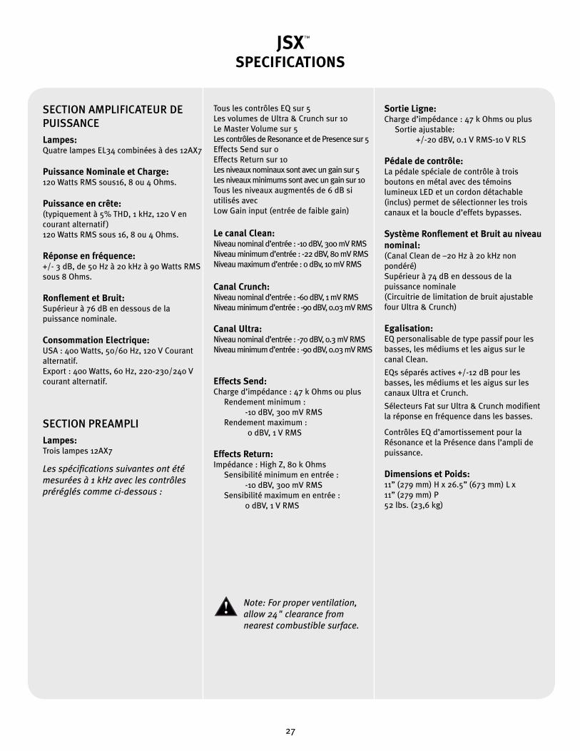
SECTION AMPLIFICATEUR DE PUISSANCELampes:Quatre lampes EL34 combinées à des 12AX7
Puissance Nominale et Charge:120 Watts RMS sous16, 8 ou 4 Ohms.
Puissance en crête:(typiquement à 5% THD, 1 kHz, 120 V en courant alternatif )120 Watts RMS sous 16, 8 ou 4 Ohms.
Réponse en fréquence: +/- 3 dB, de 50 Hz à 20 kHz à 90 Watts RMS sous 8 Ohms.
Ronflement et Bruit:Supérieur à 76 dB en dessous de la puissance nominale.
Consommation Electrique:USA : 400 Watts, 50/60 Hz, 120 V Courant alternatif.Export : 400 Watts, 60 Hz, 220-230/240 V courant alternatif.
SECTION PREAMPLILampes:Trois lampes 12AX7
Les spécifications suivantes ont été mesurées à 1 kHz avec les contrôles préréglés comme ci-dessous :
Tous les contrôles EQ sur 5Les volumes de Ultra & Crunch sur 10Le Master Volume sur 5Les contrôles de Resonance et de Presence sur 5Effects Send sur 0Effects Return sur 10Les niveaux nominaux sont avec un gain sur 5Les niveaux minimums sont avec un gain sur 10Tous les niveaux augmentés de 6 dB si utilisés avecLow Gain input (entrée de faible gain)
Le canal Clean: Niveau nominal d’entrée : -10 dBV, 300 mV RMSNiveau minimum d’entrée : -22 dBV, 80 mV RMSNiveau maximum d’entrée : 0 dBv, 10 mV RMS
Canal Crunch:Niveau nominal d’entrée : -60 dBV, 1 mV RMSNiveau minimum d’entrée : -90 dBV, 0.03 mV RMS
Canal Ultra:Niveau nominal d’entrée : -70 dBV, 0.3 mV RMSNiveau minimum d’entrée : -90 dBV, 0.03 mV RMS
Effects Send:Charge d’impédance : 47 k Ohms ou plus Rendement minimum : -10 dBV, 300 mV RMS Rendement maximum : 0 dBV, 1 V RMS
Effects Return:Impédance : High Z, 80 k Ohms Sensibilité minimum en entrée : -10 dBV, 300 mV RMS Sensibilité maximum en entrée : 0 dBV, 1 V RMS
Sortie Ligne:Charge d’impédance : 47 k Ohms ou plus Sortie ajustable: +/-20 dBV, 0.1 V RMS-10 V RLS
Pédale de contrôle:La pédale spéciale de contrôle à trois boutons en métal avec des témoins lumineux LED et un cordon détachable (inclus) permet de sélectionner les trois canaux et la boucle d’effets bypasses.
Système Ronflement et Bruit au niveau nominal: (Canal Clean de –20 Hz à 20 kHz non pondéré)Supérieur à 74 dB en dessous de la puissance nominale(Circuitrie de limitation de bruit ajustable four Ultra & Crunch)
Egalisation:EQ personalisable de type passif pour les basses, les médiums et les aigus sur le canal Clean. EQs séparés actives +/-12 dB pour les basses, les médiums et les aigus sur les canaux Ultra et Crunch. Sélecteurs Fat sur Ultra & Crunch modifient la réponse en fréquence dans les basses. Contrôles EQ d’amortissement pour la Résonance et la Présence dans l’ampli de puissance.
Dimensions et Poids: 11’’ (279 mm) H x 26.5’’ (673 mm) L x 11’’ (279 mm) P52 lbs. (23,6 kg)
™
27

Herzlichen Glückwunsch! Sie haben gerade einen Peavey JSX
Gitarrenverstärker erworben. Mit dem JSX wird ein Gitarristentraum
wahr, denn der Verstärker liefert hervorragende Soundqualität
und viel Leistung für jede Art von Gitarrenspiel. Für den Bau
dieses robusten Verstärkers, der sich durch tollen Klang und ein
einzigartiges Design auszeichnet und der jede Tour problemlos
mitmacht, wurden nur die besten Materialien verwendet. Ich hoffe,
Ihnen gefällt dieser Verstärker genauso gut wie mir!
DEUTSCH
Eigenschaften
• Drei 12AX7-Vorstufenröhren
• Vier EL34 Endstufenröhren, angesteuert via 12AX7
• Endstufe auch für 6L6GC-Röhren geeignet
• Fußschaltbarer Effektweg mit separaten Send- und Return-Reglern
• Resonance- und Presence-Damping-Regler
• Vollständig regulierbare Noise-Gate-Schaltung an Ultra- und Crunch-Kanal
• Line-Ausgang mit Pegelregler
• Impedanzwahlschalter für die Lautsprecherausgänge (4, 8 oder 16 Ohm)
• Robuste Schalter (Toggle-Switches) für Power, Standby und Kanalanwahl
• Klassische Netzstatusanzeige
• Verchromte Messing-Regler
Joe Satriani
™
28
F R O N T P L AT T E
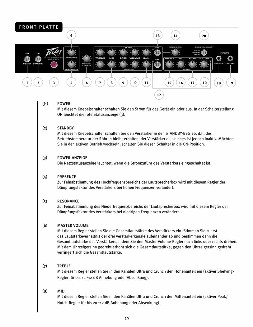
((1) POWERMit diesem Knebelschalter schalten Sie den Strom für das Gerät ein oder aus. In der Schalterstellung ON leuchtet die rote Statusanzeige (3).
(2) STANDBYMit diesem Knebelschalter schalten Sie den Verstärker in den STANDBY-Betrieb, d.h. die Betriebstemperatur der Röhren bleibt erhalten, der Verstärker als solches ist jedoch inaktiv. Möchten Sie in den aktiven Betrieb wechseln, schalten Sie diesen Schalter in die ON-Position.
(3) POWER-ANZEIGEDie Netzstatusanzeige leuchtet, wenn die Stromzufuhr des Verstärkers eingeschaltet ist.
(4) PRESENCEZur Feinabstimmung des Hochfrequenzbereichs der Lautsprecherbox wird mit diesem Regler der Dämpfungsfaktor des Verstärkers bei hohen Frequenzen verändert.
(5) RESONANCEZur Feinabstimmung des Niederfrequenzbereichs der Lautsprecherbox wird mit diesem Regler der Dämpfungsfaktor des Verstärkers bei niedrigen Frequenzen verändert.
(6) MASTER VOLUMEMit diesem Regler stellen Sie die Gesamtlautstärke des Verstärkers ein. Stimmen Sie zuerst das Lautstärkeverhältnis der drei Verstärkerkanäle aufeinander ab und bestimmen dann die Gesamtlautstärke des Verstärkers, indem Sie den Master-Volume-Regler nach links oder rechts drehen. Mit dem Uhrzeigersinn gedreht erhöht sich die Gesamtlautstärke; gegen den Uhrzeigersinn gedreht verringert sich die Gesamtlautstärke.
(7) TREBLEMit diesem Regler stellen Sie in den Kanälen Ultra und Crunch den Höhenanteil ein (aktiver Shelving-
Regler für bis zu ˜12 dB Anhebung oder Absenkung).
(8) MID Mit diesem Regler stellen Sie in den Kanälen Ultra und Crunch den Mittenanteil ein (aktiver Peak/
Notch-Regler für bis zu ˜12 dB Anhebung oder Absenkung).
1 3 5 7 9 11
13
152
4
6 8 10
14
16 10
12
19
20
17 18
29
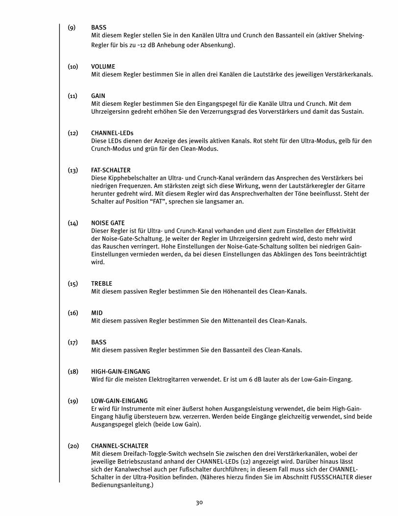
(9) BASS Mit diesem Regler stellen Sie in den Kanälen Ultra und Crunch den Bassanteil ein (aktiver Shelving-
Regler für bis zu ˜12 dB Anhebung oder Absenkung).
(10) VOLUMEMit diesem Regler bestimmen Sie in allen drei Kanälen die Lautstärke des jeweiligen Verstärkerkanals.
(11) GAINMit diesem Regler bestimmen Sie den Eingangspegel für die Kanäle Ultra und Crunch. Mit dem Uhrzeigersinn gedreht erhöhen Sie den Verzerrungsgrad des Vorverstärkers und damit das Sustain.
(12) CHANNEL-LEDsDiese LEDs dienen der Anzeige des jeweils aktiven Kanals. Rot steht für den Ultra-Modus, gelb für den Crunch-Modus und grün für den Clean-Modus.
(13) FAT-SCHALTERDiese Kipphebelschalter an Ultra- und Crunch-Kanal verändern das Ansprechen des Verstärkers bei niedrigen Frequenzen. Am stärksten zeigt sich diese Wirkung, wenn der Lautstärkeregler der Gitarre herunter gedreht wird. Mit diesem Regler wird das Ansprechverhalten der Töne beeinflusst. Steht der Schalter auf Position “FAT”, sprechen sie langsamer an.
(14) NOISE GATEDieser Regler ist für Ultra- und Crunch-Kanal vorhanden und dient zum Einstellen der Effektivität der Noise-Gate-Schaltung. Je weiter der Regler im Uhrzeigersinn gedreht wird, desto mehr wird das Rauschen verringert. Hohe Einstellungen der Noise-Gate-Schaltung sollten bei niedrigen Gain-Einstellungen vermieden werden, da bei diesen Einstellungen das Abklingen des Tons beeinträchtigt wird.
(15) TREBLEMit diesem passiven Regler bestimmen Sie den Höhenanteil des Clean-Kanals.
(16) MIDMit diesem passiven Regler bestimmen Sie den Mittenanteil des Clean-Kanals.
(17) BASSMit diesem passiven Regler bestimmen Sie den Bassanteil des Clean-Kanals.
(18) HIGH-GAIN-EINGANGWird für die meisten Elektrogitarren verwendet. Er ist um 6 dB lauter als der Low-Gain-Eingang.
(19) LOW-GAIN-EINGANGEr wird für Instrumente mit einer äußerst hohen Ausgangsleistung verwendet, die beim High-Gain-Eingang häufig übersteuern bzw. verzerren. Werden beide Eingänge gleichzeitig verwendet, sind beide Ausgangspegel gleich (beide Low Gain).
(20) CHANNEL-SCHALTERMit diesem Dreifach-Toggle-Switch wechseln Sie zwischen den drei Verstärkerkanälen, wobei der jeweilige Betriebszustand anhand der CHANNEL-LEDs (12) angezeigt wird. Darüber hinaus lässt sich der Kanalwechsel auch per Fußschalter durchführen; in diesem Fall muss sich der CHANNEL-Schalter in der Ultra-Position befinden. (Näheres hierzu finden Sie im Abschnitt FUSSSCHALTER dieser Bedienungsanleitung.)
30
R Ü C K S E I T E
(21) EFFECTS SEND-REGLERMit diesem kalibrierten Trimregler (0 –10) stellen Sie den an ein externes Effektgerät oder anderen Signalprozessor ausgegebenen Pegel ein. Mit dem Uhrzeigersinn gedreht erhöht sich der Signalanteil, gegen den Uhrzeigersinn gedreht verringert er sich. Für ein möglichst rauschfreies Signal empfiehlt sich eine hohe Einstellung des EFFECTS SEND-Pegels. Als Anhaltspunkt kann man sagen, dass SEND- und RETURN-Regler stets gegenläufig eingestellt werden sollten. Möchten Sie also einen Arbeitspegel von 0 dB (“Unity Gain”) erzielen, sollte der EFFECTS RETURN-Pegel bei niedrigem EFFECTS SEND-Pegel (24) entsprechend hoch eingestellt sein. Möchten Sie hingegen eine Anhebung der Gesamtlautstärke erreichen, stellen Sie beide Regler höher ein.
(22/23) EFFECTS SEND / EFFECTS RETURN Diese beiden 6,3-mm-Monoklinkenbuchsen dienen der Anbindung externer Effektgeräte oder anderer Signalprozessoren. Führen Sie zu diesem Zweck ein abgeschirmtes Kabel mit 6,3-mm-Monoklinkensteckern von der EFFECTS SEND-Buchse (17) zum Eingang des externen Geräts und ein weiteres vom Ausgang des Geräts zur EFFECTS RETURN-Buchse (18). Derartige Einschleifwege (“Effektwege”) eignen sich für alle Prozessoren, die das Signal nicht zusätzlich verstärken (Chorus, Delay, Reverb etc.). Bei Verwendung des Fußschalters aktivieren Sie den Einschleifweg über den EFFECTS-Schalter (37). (Näheres hierzu finden Sie im Abschnitt FUSSSCHALTER dieser Bedienungsanleitung.)
(24) EFFECTS RETURN-REGLERMit diesem kalibrierten Trimregler (0 –10) stellen Sie den von einem externen Effektgerät oder anderen Signalprozessor zurückgeführten Signalpegel ein. Mit dem Uhrzeigersinn gedreht erhöht sich der Signalanteil, gegen den Uhrzeigersinn gedreht verringert er sich. Auch hier gilt, dass SEND- und RETURN-Regler stets gegenläufig eingestellt werden sollten. Für ein möglichst rauschfreies Signal empfiehlt sich eine hohe Einstellung des SEND-Pegels bei entsprechend niedriger Einstellung des RETURN-Pegels.
(25) REMOTE SWITCHAn diese 7-polige DIN-Buchse schließen Sie den Fußschalter an. Beachten Sie, dass die Kabelverbindung bei Einschalten des Verstärkers bereits bestehen sollte. (Näheres hierzu finden Sie im Abschnitt FUSSSCHALTER dieser Bedienungsanleitung.)
(26) BIAS TESTDiese Anschlüsse sind für das Einmessen der Endstufenröhren (Bias-Abgleich) des Verstärkers vorgesehen. Zu diesem Zweck befindet sich hinter der rückwärtigen Verstärkerabdeckung ein spezieller Regler, dessen Einstellung jedoch nur vom Fachmann verändert werden sollte.
22 24 26
21 25 27 2923
28 30
32
31
33
31
(27) CABINET IMPEDANCEMit diesem Dreifach-Schalter stellen Sie die Lautsprecherimpedanz ein. Bei Anschluss zweier Lautsprecherboxen mit identischen Impedanzwerten setzen Sie diesen Schalter auf den halben Wert einer Box. Bei zwei 16-Ohm-Boxen stellen Sie den Impedanzwahlschalter also auf 8 Ohm ein, bei zwei 8-Ohm-Boxen auf 4 Ohm (Mindestimpedanz 4 Ohm).
(28) SPEAKER OUTPUTSAn diese beiden parallelgeschalteten 6,3-mm-Monoklinkenbuchsen schließen Sie die Lautsprecherbox(en) an, wobei die Mindestimpedanz 4 Ohm beträgt. Stellen Sie den Impedanzwahlschalter (CABINET IMPEDANCE, 27) stets so ein, dass er der Impedanz der verwendeten Lautsprecherbox(en) entspricht.
(29) LINE OUT LEVELMit diesem Regler bestimmen Sie den Signalpegel für den LINE-Ausgang (LINE OUT, 30), z.B. wenn Sie die Lautstärke einer zweiten, via LINE OUT (30) als "Slave" angesteuerten Leistungsverstärker/Lautsprecher-Kombination an den Pegel der via SPEAKER OUTPUTS (28) direkt angesteuerten Lautsprecher angleichen möchten.
(30) LINE OUTDiese 6,3-mm-Monoklinkenbuchse bietet die Möglichkeit, das Vorstufensignal des Verstärkers abzugreifen, um z.B. unter Beibehaltung der Klangcharakteristik eine weitere Leistungsverstärker/Lautsprecher-Kombination anzusteuern.
(31) FUSE (NETZSICHERUNG)Die Netzsicherung befindet sich in der Sicherungshalterung. Sollte die Sicherung auslösen, ist es unbedingt erforderlich, sie durch eine gleichartige Sicherung zu ersetzen, da das Gerät sonst ernstlichen Schaden nehmen kann und Ihr Garantieanspruch erlischt. Falls die Sicherung wiederholt auslöst, sollten Sie das Gerät unbedingt durch einen qualifizierten Service-Techniker überprüfen lassen.
WARNUNG: ERSETZEN SIE DIE NETZSICHERUNG AUSSCHLIESSLICH BEI GEZOGENEM NETZSTECKER!
(32) GROUND POLARITYFür die meisten Anwendungen sollte sich dieser Dreifach-Wippschalter in Mittelposition (Nullposition) befinden. Eventuelles Brummen lässt sich durch Umschalten des Polaritätswahlschalters in die positive (+) bzw. negative (-) Position minimieren. Bei anhaltenden Brummproblemen wenden Sie sich an einen Peavey-Vertragshändler, direkt an Peavey oder an einen qualifizierten Service-Techniker.
(33) IEC MAINSAn diese Normbuchse schließen Sie das im Lieferumfang enthaltene, den Spannungswerten Ihres Landes entsprechende Netzkabel an. Stellen Sie stets zuerst die verstärkerseitige Verbindung her, bevor Sie das Kabel in die Netzsteckdose stecken.
Entfernen oder umgehen Sie an Ihrem Equipment niemals die Erdleiter, da diese Ihrer Sicherheit dienen.
32
F U S S S C H A LT E R
(34) REMOTE CABLE
An diese 7-polige DIN-Buchse schließen Sie das im Lieferumfang enthaltene Fußschalter-
Anschlusskabel an und verbinden es mit dem Fußschaltereingang des Verstärkers (REMOTE SWITCH,
25). Beachten Sie, dass die Kabelverbindung bei Einschalten des Verstärkers bereits bestehen sollte.
(35) ULTRA/CRUNCH
Mit diesem Schalter wechseln Sie zwischen den Verstärkerkanälen Ultra und Crunch, wobei die Anwahl
des Ultra-Kanals durch die zugehörige LED angezeigt wird. Leuchtet die LED nicht, ist der Crunch-Kanal
aktiviert. Beachten Sie, dass sich der Schalter für den CLEAN-Kanal (36) bei Anwahl des Ultra- bzw.
Crunch-Kanals im BYPASS-Modus befinden muss.
(36) CLEAN
Mit diesem Schalter wählen Sie unabhängig von der Position des ULTRA/CRUNCH-Wahlschalters (35)
den Clean-Kanal an, wobei die Aktivierung des Clean-Kanals durch die zugehörige LED angezeigt wird.
Beachten Sie, dass sich dieser Schalter vor Betätigen des ULTRA/CRUNCH-Wahlschalters (35) im
BYPASS-Modus befinden muss (d.h. die LED für den Clean-Kanal leuchtet nicht).
(37) EFFECTS
Mit diesem Schalter aktivieren Sie den Effektweg des Verstärkers (21 – 24), angezeigt durch die
zugehörige LED.
35 37
34
36
33
JSXTECHNISCHE DATENJSX Block Diagram
Note: For proper ventilation‚ allow 24" clearance from nearest combustible surface.
ENDSTUFE:Röhren:Vier EL34-Röhren mit 12AX7-Treiber Nennleistung und Nennlast:120 Watt RMS an 16, 8 oder 4 Ohm
Leistung bei Clipping:(typisch bei 5% THD, 1 kHz, 120 V Wechselstromleitung)120 Watt RMS an 16, 8 oder 4 Ohm
Frequenzgang:+/-3 dB, 50 Hz bis 20 kHz bei 90 W RMS an 8 Ohm
Brummen und Rauschen:Mehr als 76 dB unter Nennleistung
Leistungsaufnahme: USA: 400 Watt, 50/60 Hz, 120 V WechselstromExport: 400 Watt, 60 Hz, 220-230/240 V Wechselstrom
VORVERSTÄRKER:Röhren:Drei 12AX7-Röhren
Die folgenden technischen Daten wurden bei 1 kHz mit folgenden Reglervoreinstellungen gemessen:Alle EQ-Regler bei 5Lautstärke Ultra bzw. Crunch bei 10Master Volume bei 5Resonance- und Presence-Regler bei 5Effects Send bei 0Effects Return bei 10Nennpegel mit Gain bei 5Mindestpegel mit Gain bei 10Alle Pegel um 6 dB angehoben bei Einsatz des Low-Gain-Eingangs
Clean-Kanal:Nenneingangspegel: -10 dBV, 300 mV RMSMindesteingangspegel: -22 dBV, 80 mV RMSHöchsteingangspegel: 0 dBV, 1 mV RMS
Crunch-Kanal:Nenneingangspegel: -60 dBV, 1 mV RMSMindesteingangspegel: -90 dBV, 0,03 mV RMS
Ultra-Kanal:Nenneingangspegel: -70 dBV, 0,3 mV RMSMindesteingangspegel: -90 dBV, 0,03 mV RMS
Effects Send:Verbraucherimpedanz: 47 kOhm oder darüber Mindestausgang: -10 dBV, 300 mV RMS Höchstausgang: 0 dBV, 1 V RMS
Effects Return:Impedanz: High Z, 80 kOhm Mindesteingangsempfindlichkeit: -10 dBV, 300 mV RMS Höchsteingangsempfindlichkeit: 0 dBV, 1 V RMS
Line-Ausgang:Verbraucherimpedanz: 47 kOhm oder darüber Einstellbarer Ausgang: +/- 20 dBV, 0,1 V RMS bis 10 V RMS
Fußschalter:Spezieller Dreitasten-Fußschalter aus Metall mit LED-Anzeigen und abziehbarem Kabel (beiliegend) zur Auswahl der drei Kanäle und Deaktivierung der Effektschleife.
Systembrummen und -rauschen bei Nenneingangspegel:(Clean-Kanal -20 Hz bis 20 kHz ungewichtet)Mehr als 74 dB unter Nennleistung(Einstellbare Noise-Gate-Schaltung für Ultra- und Crunch-Kanal)
Abgleich: Passiver Dreiband-EQ (Bass, Mid, Treble) am Clean-Kanal Separate aktive Dreiband-EQs (Bass, Mid, Treble, +/-12 dB) an Ultra- und Clean-Kanal Fat-Schalter an Ultra- und Crunch-Kanal zur Veränderung des Ansprechens bei niedrigen Frequenzen Resonance- und Presence-Damping-EQ-Regler an der Endstufe
Abmessungen und Gewicht:HxBxT 279 mm x 673 mm x 279 mm23,6 kg
™
™
34
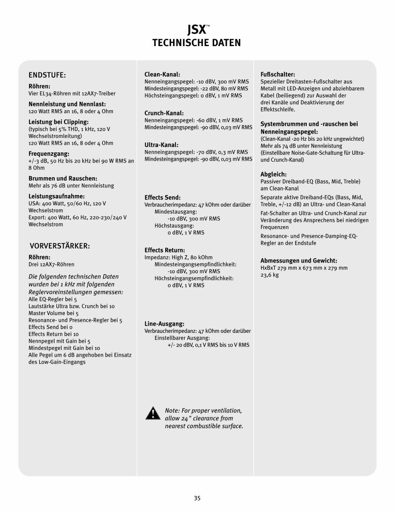
JSXTECHNISCHE DATENJSX Block Diagram
Note: For proper ventilation‚ allow 24" clearance from nearest combustible surface.
ENDSTUFE:Röhren:Vier EL34-Röhren mit 12AX7-Treiber Nennleistung und Nennlast:120 Watt RMS an 16, 8 oder 4 Ohm
Leistung bei Clipping:(typisch bei 5% THD, 1 kHz, 120 V Wechselstromleitung)120 Watt RMS an 16, 8 oder 4 Ohm
Frequenzgang:+/-3 dB, 50 Hz bis 20 kHz bei 90 W RMS an 8 Ohm
Brummen und Rauschen:Mehr als 76 dB unter Nennleistung
Leistungsaufnahme: USA: 400 Watt, 50/60 Hz, 120 V WechselstromExport: 400 Watt, 60 Hz, 220-230/240 V Wechselstrom
VORVERSTÄRKER:Röhren:Drei 12AX7-Röhren
Die folgenden technischen Daten wurden bei 1 kHz mit folgenden Reglervoreinstellungen gemessen:Alle EQ-Regler bei 5Lautstärke Ultra bzw. Crunch bei 10Master Volume bei 5Resonance- und Presence-Regler bei 5Effects Send bei 0Effects Return bei 10Nennpegel mit Gain bei 5Mindestpegel mit Gain bei 10Alle Pegel um 6 dB angehoben bei Einsatz des Low-Gain-Eingangs
Clean-Kanal:Nenneingangspegel: -10 dBV, 300 mV RMSMindesteingangspegel: -22 dBV, 80 mV RMSHöchsteingangspegel: 0 dBV, 1 mV RMS
Crunch-Kanal:Nenneingangspegel: -60 dBV, 1 mV RMSMindesteingangspegel: -90 dBV, 0,03 mV RMS
Ultra-Kanal:Nenneingangspegel: -70 dBV, 0,3 mV RMSMindesteingangspegel: -90 dBV, 0,03 mV RMS
Effects Send:Verbraucherimpedanz: 47 kOhm oder darüber Mindestausgang: -10 dBV, 300 mV RMS Höchstausgang: 0 dBV, 1 V RMS
Effects Return:Impedanz: High Z, 80 kOhm Mindesteingangsempfindlichkeit: -10 dBV, 300 mV RMS Höchsteingangsempfindlichkeit: 0 dBV, 1 V RMS
Line-Ausgang:Verbraucherimpedanz: 47 kOhm oder darüber Einstellbarer Ausgang: +/- 20 dBV, 0,1 V RMS bis 10 V RMS
Fußschalter:Spezieller Dreitasten-Fußschalter aus Metall mit LED-Anzeigen und abziehbarem Kabel (beiliegend) zur Auswahl der drei Kanäle und Deaktivierung der Effektschleife.
Systembrummen und -rauschen bei Nenneingangspegel:(Clean-Kanal -20 Hz bis 20 kHz ungewichtet)Mehr als 74 dB unter Nennleistung(Einstellbare Noise-Gate-Schaltung für Ultra- und Crunch-Kanal)
Abgleich: Passiver Dreiband-EQ (Bass, Mid, Treble) am Clean-Kanal Separate aktive Dreiband-EQs (Bass, Mid, Treble, +/-12 dB) an Ultra- und Clean-Kanal Fat-Schalter an Ultra- und Crunch-Kanal zur Veränderung des Ansprechens bei niedrigen Frequenzen Resonance- und Presence-Damping-EQ-Regler an der Endstufe
Abmessungen und Gewicht:HxBxT 279 mm x 673 mm x 279 mm23,6 kg
™
™
35

Features and specifications subject to change without notice.
Peavey Electronics Corporation • 711 A Street • Meridian • MS • 39301
(601) 483-5365 • FAX (601) 486-1278 • www.peavey.com
©2004 Printed in the U.S.A. 6/0480304994