c75-fa-6 and c75-fa-7 - zenith aircraft companyflange center line. position the instrument panel on...
TRANSCRIPT
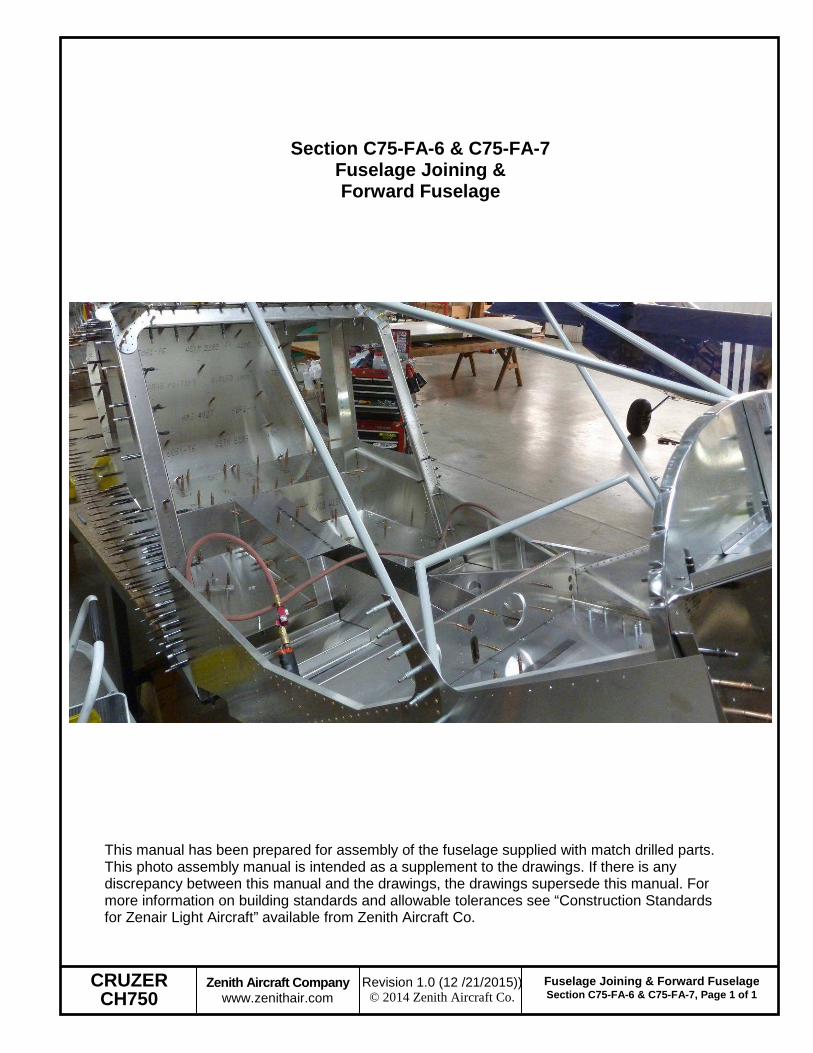
CRUZER CH750
Zenith Aircraft Company www.zenithair.com
Fuselage Joining & Forward Fuselage Section C75-FA-6 & C75-FA-7, Page 1 of 1
Revision 1.0 (12 /21/2015)) © 2014 Zenith Aircraft Co.
Section C75-FA-6 & C75-FA-7 Fuselage Joining & Forward Fuselage
This manual has been prepared for assembly of the fuselage supplied with match drilled parts. This photo assembly manual is intended as a supplement to the drawings. If there is any discrepancy between this manual and the drawings, the drawings supersede this manual. For more information on building standards and allowable tolerances see “Construction Standards for Zenair Light Aircraft” available from Zenith Aircraft Co.

CRUZER CH750
Zenith Aircraft Company www.zenithair.com
Fuselage Joining & Forward Fuselage Section C75-FA-6 & C75-FA-7, Page 2 of 2
Revision 1.0 (12 /21/2015)) © 2014 Zenith Aircraft Co.
Expand the holes on the aft edge in the Cabin Side with a #30 drill bit. Use a block of wood to support the Cabin Side while drilling. Then expand the holes with a #20 drill bit.
Slide the Longerons inside of the cutouts on the Side Channels and Flaperon Control Covers. Cleco the Cabin Side to the Side Skin and Side Channel. Cleco the Gear Channel to the Bottom Skin. Use a stand under the front end of the Forward Fuselage to support its weight.

CRUZER CH750
Zenith Aircraft Company www.zenithair.com
Fuselage Joining & Forward Fuselage Section C75-FA-6 & C75-FA-7, Page 3 of 3
Revision 1.0 (12 /21/2015)) © 2014 Zenith Aircraft Co.
With a #40 drill bit, back drill through the Side Skin into the Longeron on the Cabin Side and Cleco. Use a #20 drill bit to expand the holes and Cleco.
Cleco the Side Skin Gusset to the Side Skin and Cabin Side. With a #20 drill bit, expand the holes in the Side Skin Gusset and Cleco.
P/N: C75F4-7 Side Skin Gusset

CRUZER CH750
Zenith Aircraft Company www.zenithair.com
Fuselage Joining & Forward Fuselage Section C75-FA-6 & C75-FA-7, Page 4 of 4
Revision 1.0 (12 /21/2015)) © 2014 Zenith Aircraft Co.
P/N: C75F4-9 Longeron Gusset
Slide the Longeron Gusset between the Longeron, Baggage Back Channel, and the Side Skin and cleco.

CRUZER CH750
Zenith Aircraft Company www.zenithair.com
Fuselage Joining & Forward Fuselage Section C75-FA-6 & C75-FA-7, Page 5 of 5
Revision 1.0 (12 /21/2015)) © 2014 Zenith Aircraft Co.
Measure the distance between the Rear Wing Attachment and the first hole in the Top Doubler.
Mark the distance measured in the previous step on the top rear tubes of the Cabin Frame. With an Angle Grinder and Cutoff wheel or a Hacksaw, trim the excess material off the Cabin Frame. The top rear tubes should be cut on a 15degree angle. Follow the same procedure to mark and cut the vertical tubes for the holes in the Cabin Side. The Vertical tubes should be cut on a 5 degree angle.
P/N: C75F15-1 Cabin Frame

CRUZER CH750
Zenith Aircraft Company www.zenithair.com
Fuselage Joining & Forward Fuselage Section C75-FA-6 & C75-FA-7, Page 6 of 6
Revision 1.0 (12 /21/2015)) © 2014 Zenith Aircraft Co.
Cleco the aft most hole in the Cabin Frame to the Top Doubler. With a #40 drill bit, back drill through the Top Doubler into the Cabin Frame for the remaining holes and Cleco. Then with a #20 drill bit, expand the holes and Cleco.
The bottom most hole for the Cabin Side has been predrilled into the Cabin Frame. Cleco the Cabin Side to the Cabin Frame. With a #40 drill bit, back drill through the Cabin Side into the Cabin Frame and Cleco. Then with a #20 drill bit, expand the hole and Cleco.

CRUZER CH750
Zenith Aircraft Company www.zenithair.com
Fuselage Joining & Forward Fuselage Section C75-FA-6 & C75-FA-7, Page 7 of 7
Revision 1.0 (12 /21/2015)) © 2014 Zenith Aircraft Co.
Layout 5 rivets on each flange of the Cabin Frame Gusset and predrill the holes with a #40 drill bit. Position the Gusset on the Cabin Side and Cabin Frame. With a #40 drill bit, back drill through the Gusset into the Cabin Side and the Cabin Frame and Cleco. Then with a #20 drill bit, expand the holes and Cleco.
P/N: C75F12-4 Cabin Frame Gusset
Cleco the Firewall to the Cabin Floor.
CRUZER CH750
Zenith Aircraft Company www.zenithair.com
Fuselage Joining & Forward Fuselage Section C75-FA-6 & C75-FA-7, Page 8 of 8
Revision 1.0 (12 /21/2015)) © 2014 Zenith Aircraft Co.
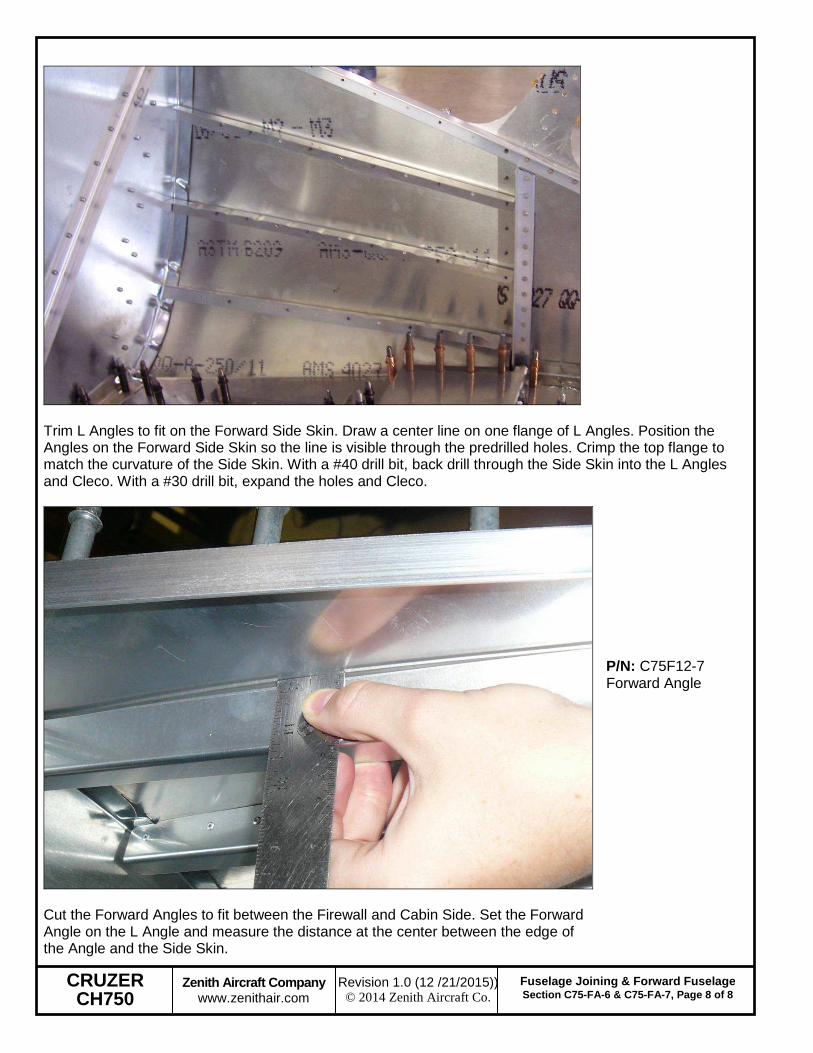
Trim L Angles to fit on the Forward Side Skin. Draw a center line on one flange of L Angles. Position the Angles on the Forward Side Skin so the line is visible through the predrilled holes. Crimp the top flange to match the curvature of the Side Skin. With a #40 drill bit, back drill through the Side Skin into the L Angles and Cleco. With a #30 drill bit, expand the holes and Cleco.
Cut the Forward Angles to fit between the Firewall and Cabin Side. Set the Forward Angle on the L Angle and measure the distance at the center between the edge of the Angle and the Side Skin.
P/N: C75F12-7 Forward Angle

CRUZER CH750
Zenith Aircraft Company www.zenithair.com
Fuselage Joining & Forward Fuselage Section C75-FA-6 & C75-FA-7, Page 9 of 9
Revision 1.0 (12 /21/2015)) © 2014 Zenith Aircraft Co.
Make a mark at each end of the Angles at the distance measured in the previous step. Make a smooth curve to the center of the Angle from the marks at each end. Trim the Angle along the line to match the curvature of the Side Skin.
Mark the crimp locations in the L Angle on the Side Skin. Clamp the Forward Angle to the L Angle. Layout a 40mm rivet pitch making sure to miss the crimps in the L Angle, 10mm from the edge of the Forward Angle. With an Angle Drill and a #40 drill bit, drill the rivet locations in the Forward Angle into the L Angle and Cleco. Use a #30 drill bit to expand the holes.
CRUZER CH750
Zenith Aircraft Company www.zenithair.com
Fuselage Joining & Forward Fuselage Section C75-FA-6 & C75-FA-7, Page 10 of 10
Revision 1.0 (12 /21/2015)) © 2014 Zenith Aircraft Co.
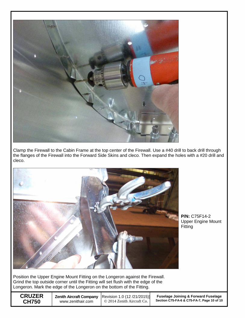
Clamp the Firewall to the Cabin Frame at the top center of the Firewall. Use a #40 drill to back drill through the flanges of the Firewall into the Forward Side Skins and cleco. Then expand the holes with a #20 drill and cleco.
Position the Upper Engine Mount Fitting on the Longeron against the Firewall. Grind the top outside corner until the Fitting will set flush with the edge of the Longeron. Mark the edge of the Longeron on the bottom of the Fitting.
P/N: C75F14-2 Upper Engine Mount Fitting

CRUZER CH750
Zenith Aircraft Company www.zenithair.com
Fuselage Joining & Forward Fuselage Section C75-FA-6 & C75-FA-7, Page 11 of 11
Revision 1.0 (12 /21/2015)) © 2014 Zenith Aircraft Co.
Layout a hole 10mm from the aft end of the Upper Engine Mount Fitting centered on the Longeron. Layout a hole 10mm from the front edge of the Longeron on the Upper Engine Mount Fitting centered on the Longeron. With a #40 drill bit, predrill the holes for the bolts in the Upper Engine Mount Fittings. Position the Upper Engine Mount Fitting on the Longeron, drill with a #40 drill bit, and Cleco. Expand the holes to 3/16” and Cleco.
Position the Lower Engine Mount on the Cabin Floor against the Firewall. Center the front flange on the hole for the Engine Mount Bolt. Check the edge distance on the holes through the Longeron on the Lower Engine Mount Fitting. Back drill through the Longeron into the Lower Engine Mount Fitting and Cleco. Expand the Holes to 3/16” and Cleco or bolt.
P/N: C75F14-1 Lower Engine Mount Fitting

CRUZER CH750
Zenith Aircraft Company www.zenithair.com
Fuselage Joining & Forward Fuselage Section C75-FA-6 & C75-FA-7, Page 12 of 12
Revision 1.0 (12 /21/2015)) © 2014 Zenith Aircraft Co.
Draw a line on the top flange of the Instrument Panel at the center and mark the flange center line. Position the Instrument Panel on the Cabin Frame. Check to be sure the Instrument Panel is centered. Clamp the Instrument Panel to the Cabin Frame.
P/N: C75F16-1 Instrument Panel Note: Wait to drill the Instrument Panel until the Forward Top Skin is installed.
Position the Forward Top Skin over the Firewall and Instrument Panel. Find the hole in the center of the Forward Top Skin for the Instrument panel and position it at the intersection of the Instrument Panel center line and flange center line. Use a #40 drill bit to back drill through the Skin into the Panel and cleco.
P/N: C75F16-2 Forward Top Skin Note: The Cabin Frame passes through the cutout in the front of the Forward Top Skin and the Firewall may need to be unclecoed from the sides to slip it in position.

CRUZER CH750
Zenith Aircraft Company www.zenithair.com
Fuselage Joining & Forward Fuselage Section C75-FA-6 & C75-FA-7, Page 13 of 13
Revision 1.0 (12 /21/2015)) © 2014 Zenith Aircraft Co.
Draw a line centered on the flange of the Firewall. Also make the center of the firewall on the top flange and front of the Firewall.
With a #40 drill bit, back drill through the Forward Top Skin into the Firewall. Start in the center and work to each edge. Cleco every hole as they are drilled to pull the Skin tight to the Firewall. Back drill through the Side Skin into the Top Skin and Longerons and Cleco. With a #20 drill bit, expand the holes for the Firewall and Longeron and Cleco. With a #30 drill bit, expand the holes through the Instrument Panel.

CRUZER CH750
Zenith Aircraft Company www.zenithair.com
Fuselage Joining & Forward Fuselage Section C75-FA-6 & C75-FA-7, Page 14 of 14
Revision 1.0 (12 /21/2015)) © 2014 Zenith Aircraft Co.
Cut L Angles to fit between the Instrument Panel and the Firewall. Draw a center line on one flange of the L Angles. Position the L Angles on the Top Skin so the center line is visible through the predrilled holes. Crimp the L Angles as required to fit the skin. With a #30 drill bit, back drill through the Top Skin into the L Angles and Cleco.
Position the Gear Strut Fitting on the Fuselage. The bottom aft should be flush with the edge of the Skin. The bottom front should be flush with the bottom of the Cabin Side. Extend the rivet lines onto the Gear Strut Fitting to lay out the bolt locations on both front and rear side of the Gear Strut Fitting.
P/N: C75F14-3 Gear Strut Fitting

CRUZER CH750
Zenith Aircraft Company www.zenithair.com
Fuselage Joining & Forward Fuselage Section C75-FA-6 & C75-FA-7, Page 15 of 15
Revision 1.0 (12 /21/2015)) © 2014 Zenith Aircraft Co.
Mark a hole location 10mm from the ends and one half way between. Layout a rivet location 10mm from the edge, half way between the bolt locations.
Extend the rivet lines and mark 4 evenly spaced bolt hole locations on the vertical line. Mark a line 10mm from the cropped edge and extend the bottom rivet line. Mark a bolt hole location half way between the intersection and the vertical line. Then make a rivet location centered on the line along the cropped edge.

CRUZER CH750
Zenith Aircraft Company www.zenithair.com
Fuselage Joining & Forward Fuselage Section C75-FA-6 & C75-FA-7, Page 16 of 16
Revision 1.0 (12 /21/2015)) © 2014 Zenith Aircraft Co.
With a #40 drill bit, drill the bolt and rivet locations on the Gear Strut Fitting into the Fuselage and cleco. Expand all the holes with a #20 drill bit and cleco. Expand the 10 holes for the bolts to 3/16”, then expand the top hole in the Gear Strut Fitting through the Side Channel to 1/4".
Draw a center line on the Gear Channel Doubler. Position the Gear Channel Doubler on the Gear Channel. When the Line is visible through the holes in the Gear Strut Fitting, back drill through the Gear Strut Fitting into the Gear Channel Doubler (photo right). Then layout 12 rivet locations evenly spaced. Cleco the Gear Channel Doubler to the Gear Channel. With a #40 drill bit, back drill through the Doubler into the Gear Channel and cleco. Expand the holes with a #20 drill bit and cleco. Expand the holes through the Gear Strut Fitting and the final hole in the Doubler to 3/16”.
P/N: C75F10-2 Gear Channel Doubler

CRUZER CH750
Zenith Aircraft Company www.zenithair.com
Fuselage Joining & Forward Fuselage Section C75-FA-6 & C75-FA-7, Page 17 of 17
Revision 1.0 (12 /21/2015)) © 2014 Zenith Aircraft Co.
Cut a piece of L angle 150mm long. Mark the center line on one flange. Mark a rivet location 10mm from each end of the L angle, then even space 3 more rivet locations. With a #40 drill bit, predrill the holes in the L angle. Position the L angle on the Gear Channel against the Cabin Side. Back drill through the L angle into the Cabin Side and cleco. Back drill through the Gear Channel into the L angle and cleco. With a #30 drill bit, expand the holes and cleco.
Seat base angle C75F11-7/1 (shown with the channels for the sliding seat option).

CRUZER CH750
Zenith Aircraft Company www.zenithair.com
Fuselage Joining & Forward Fuselage Section C75-FA-6 & C75-FA-7, Page 18 of 18
Revision 1.0 (12 /21/2015)) © 2014 Zenith Aircraft Co.
Rivets through the gear strut fitting are pulled from the inboard side.
Seat base C75F11-4

CRUZER CH750
Zenith Aircraft Company www.zenithair.com
Fuselage Joining & Forward Fuselage Section C75-FA-6 & C75-FA-7, Page 19 of 19
Revision 1.0 (12 /21/2015)) © 2014 Zenith Aircraft Co.
Drill the rivet line through the seat base angle C75F11-7
Remove the Seat Base and reinstall the Seat Support and Arm Rest Side. Cleco the Seat Base back in place. With a #30 drill bit, expand the remaining holes and cleco.

CRUZER CH750
Zenith Aircraft Company www.zenithair.com
Fuselage Joining & Forward Fuselage Section C75-FA-6 & C75-FA-7, Page 20 of 20
Revision 1.0 (12 /21/2015)) © 2014 Zenith Aircraft Co.
Position the Inboard Seat Belt Attachment on the Gear Channel against the Arm Rest Side. With a #40 drill bit, back drill through the Seat Belt Attachment into the Arm Rest Side. Expand the holes with a #20 drill bit and Cleco.
P/N: 75F13-7 Inboard Seat Belt Attachment
The Seat Base is positioned under the Lower Baggage Floor. With a #40 drill bit, back drill through the Lower Baggage Floor into the Seat Base and Cleco. Expand the holes with a #30 drill bit and Cleco.

CRUZER CH750
Zenith Aircraft Company www.zenithair.com
Fuselage Joining & Forward Fuselage Section C75-FA-6 & C75-FA-7, Page 21 of 21
Revision 1.0 (12 /21/2015)) © 2014 Zenith Aircraft Co.
Cleco the Arm Rest Top to the Arm Rest Sides and to the Control Tunnel Top. With a #30 drill bit, expand the holes through the Arm Rest Top into the Arm Rest Sides and Control Tunnel Top.
P/N: 75F11-5 Arm Rest Top Note: The back flange of the Arm Rest Top is Clecoed under the Control Tunnel Top.
With a #30 drill bit, expand the holes in the Arm Rest Sides into the Control Tunnel Sides and Cleco.