c60 table of contents daily use - danfosspfheating.danfoss.com/pcmpdf/vi7cb402.pdf · save energy -...
TRANSCRIPT
ECL COMFORT
ECL Comfort User’s Guide
C60
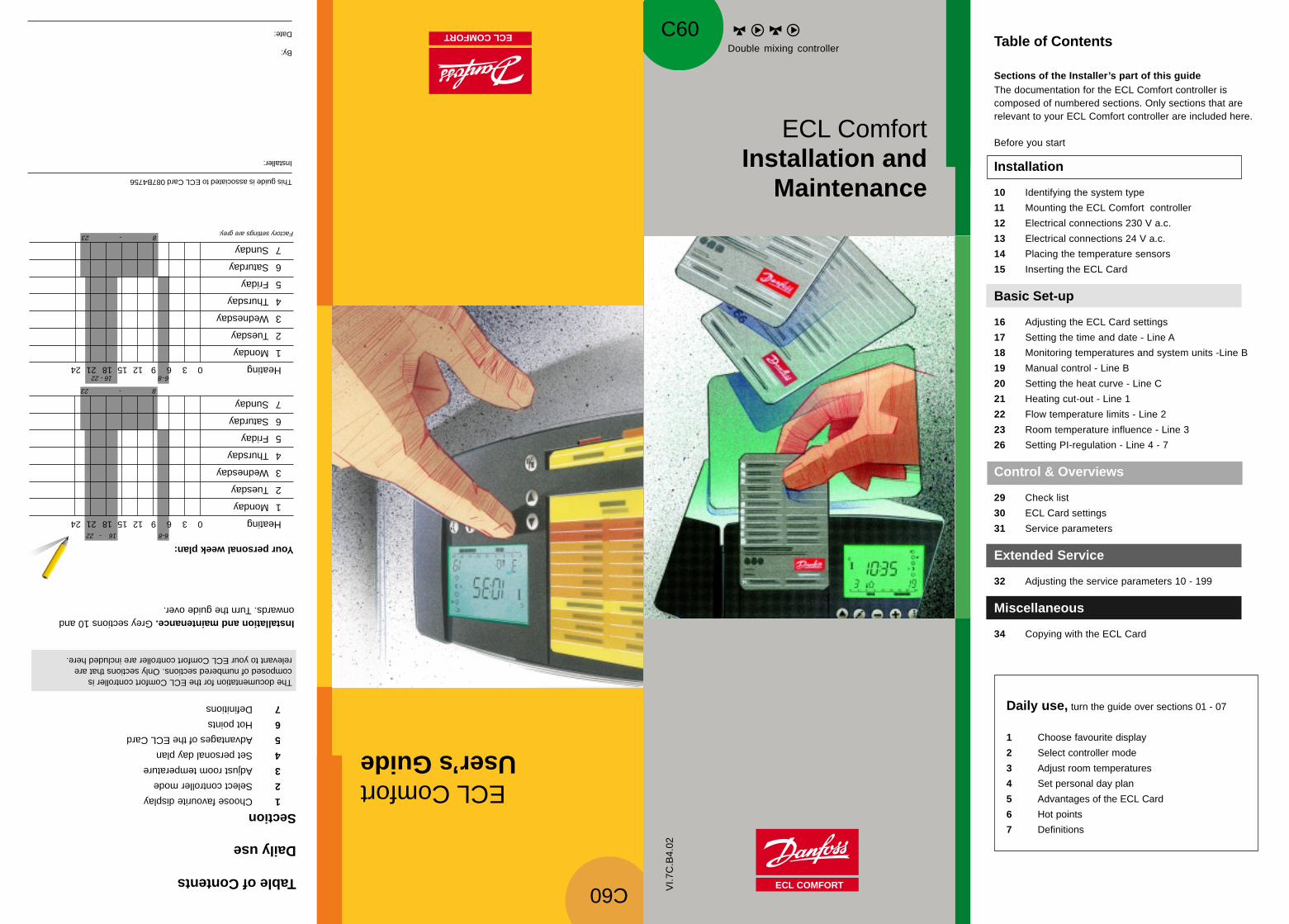
Your personal week plan:
Heating03691215182124
1Monday
2Tuesday
3Wednesday
4Thursday
5Friday
6Saturday
7Sunday
Heating03691215182124
1Monday
2Tuesday
3Wednesday
4Thursday
5Friday
6Saturday
7Sunday
Factory settings are grey.823 -
6 - 816 - 22
6-816 - 22
This guide is associated to ECL Card 087B4756
Installer:
By:
Date:ECL COMFORT
ECL Comfort Installation and
Maintenance
823 -
C60
VI.7
C.B
4.02
Table of Contents
Daily use
Section1Choose favourite display
2Select controller mode
3Adjust room temperature
4Set personal day plan
5Advantages of the ECL Card
6Hot points
7Definitions
The documentation for the ECL Comfort controller iscomposed of numbered sections. Only sections that arerelevant to your ECL Comfort controller are included here.
Installation and maintenance. Grey sections 10 andonwards. Turn the guide over.
Table of Contents
Sections of the Installer’s part of this guideThe documentation for the ECL Comfort controller iscomposed of numbered sections. Only sections that arerelevant to your ECL Comfort controller are included here.
Before you start
Installation
10 Identifying the system type
11 Mounting the ECL Comfort controller
12 Electrical connections 230 V a.c.
13 Electrical connections 24 V a.c.
14 Placing the temperature sensors
15 Inserting the ECL Card
Basic Set-up
16 Adjusting the ECL Card settings
17 Setting the time and date - Line A
18 Monitoring temperatures and system units -Line B
19 Manual control - Line B
20 Setting the heat curve - Line C
21 Heating cut-out - Line 1
22 Flow temperature limits - Line 2
23 Room temperature influence - Line 3
26 Setting PI-regulation - Line 4 - 7
Control & Overviews
29 Check list
30 ECL Card settings
31 Service parameters
Extended Service
32 Adjusting the service parameters 10 - 199
Miscellaneous
34 Copying with the ECL Card
Daily use, turn the guide over sections 01 - 07
1 Choose favourite display
2 Select controller mode
3 Adjust room temperatures
4 Set personal day plan
5 Advantages of the ECL Card
6 Hot points
7 Definitions
Double mixing controller

The shown diagram is a fundamental and simplifiedexample and does not contain all components that arenecessary in heating systems.
If the system you are about to install is different than theshown diagram of a standard heating system, feel free tosketch an outline for comparison. Adaptation of heatingsystems, see section 10.
List of components:
ECL Comfort 300
S1 Outdoor temperature sensor (ESM-10)
S2 Room temperature sensor (ESM-10) - circuit I
S3 Flow temperature sensor (ESM-) - circuit I
S4 Return temperature sensor (ESM-)
S5 Flow temperature sensor (ESM-) - circuit II
S6 Room temperature sensor (ESM-) - circuit II
P1 Circulation pump for heating - circuit I
P2 Circulation pump for heating - circuit II
M1 Mixing valve with motor - circuit I
M2 Mixing valve with motor - circuit II
Installation & maintenance
The ECL Card, grey sidefor installation and maintenance.
Lines A to C, and lines 1 to7 for basic settings, see overviewsection 30.
Extended service parameters,see section 31
The ECL Card: Installer’sinstructionThe grey side of the card must faceyou when you change settings. Fordaily use and during start-up, theyellow side of the card must face you.
Circuitselector
Shiftbutton
Adjustment Controllermode
Controller mode
Manual operation (used only atmaintenance and service)
Automatic operation
Constant comfort temperature
Constant reduced temperature
Standby mode
Arrow buttons. Switch betweenthe lines of the ECL Card.
Shift button. Switches betweentemperatures, changeover points etc.
Adjust temperatures and values etc.
Circuit selector for switching betweenheating circuit I and II.
The circuit indicator shows the selected heating circuit.
The ECL CardFor daily use and your personal adjustments the yellow sideof the ECL Card must be facing you.
The displayEach line, A, B, C, 1, 2 etc. of the ECL Card has its owndisplay. See section 1.
Controller mode
Manual operation (used only atmaintenance and service)
Automatic operation
Constant comfort temperature
Constant reduced temperature
Standby mode
Arrow buttons. Switch betweenthe lines of the ECL Card.
Shift button. Switches betweentemperatures, changeover points etc.
Adjust temperatures and values etc.
Circuit selector for switching betweenheating circuit I and II.
Roomtemperature I /
Room temperature II
Heating systeminformation
Today’sprogramme
Day plans
A
B
C
12345
67
Heating - circuit II Heating - circuit ILine indicator
Circuit
91 3
208
A
503 6
B
11
ON
2
ON
2
503 6
B
11
ON
2
ON
2
91 3
20-
A
603691215
05
0
803691215182124
0
7
0
12
34
66
21
34
803691215182124
191 3
5-
C
3
603691215
05
0
803691215182124
0
7
0Circuit indicator
803691215182124
191 3
5C
3
Save energy - save money - improve your comforttemperatureThe ECL Comfort controller is designed by Danfoss fortemperature control of heating systems.
The ECL Comfort controller ensures you of the following;• Room and hot water temperatures will be adjusted to
your personal settings.• Lower temperatures and lower energy consumption
reduce costs and ensure optimum use of energyresources.
• The automatic pump motion program protects thecirculation pump against blocking.
Sketch an outline of your heating systemThe ECL Comfort controller is designed for a wide range ofheating systems with different configurations andcapacities.If your heating system differs from the diagrams shown insection 10, you may want to sketch an outline of thesystem about to be installed. This makes it easier to use theInstaller’s Guide, which will guide you step-by-step frominstallation to final adjustments before the end-user takesover.
Note! The controller is pre-programmed with factorysettings which are shown in the relevant sections of thisguide.
However, you might come across some settings thatare not listed in this instruction. These settings are used inconnection with optional modules, and you can find adescription of the settings and the correspondingparameters in the instruction for optional module inquestion.
How to use this guideThis guide is divided into two parts:
• Daily Use (Turn the guide over)Yellow sections 1-7
• Installation and maintenance:Grey sections 10 and onwards
Before you start
VI.7
C.B
4.02

Installatio
n
Note!System diagrams in this instruction are principal drawings anddo not contain all components which are necessary in heatingsystems.
Identifying the system type10aIn this section you find the most frequently used systems. Ifyour system is not quite as shown below, find the diagramwhich has the best resemblance to your system and makeyour own combinations.
Inst
alla
tio
n
Alternatives using the same settings:• Heat exchanger or direct district heating• 2-, 3-, or 4-way control valve
Heating system type 3Radiator heating circuit and secondary connected floorheating circuit.
Set line 17 to 4KCheck line 24 in circuit I and II (gear motor/thermo actuator)
Heating system type 1Two parallel connected heating circuits with heatexchangers.
Set line 17 to OFFCheck line 24 in circuit I and II (gear motor/thermo actuator)
Heating system type 2Two parallel connected heating circuits.
Set line 17 to OFFCheck line 24 i circuit I and II (gear motor/thermo actuator)
Heating system type 4Boiler with two parallel connected heating circuits with heatexchangers.
Set line 17 to OFFCheck line 24 in circuit I and II (gear motor/thermo actuator)
10b
Mounting the ECL Comfortcontroller
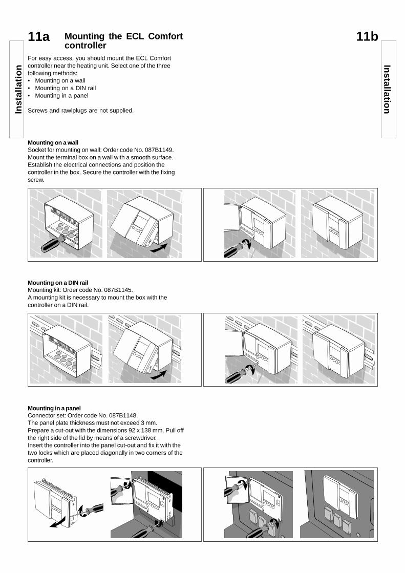
11aFor easy access, you should mount the ECL Comfortcontroller near the heating unit. Select one of the threefollowing methods:• Mounting on a wall• Mounting on a DIN rail• Mounting in a panel
Screws and rawlplugs are not supplied.
Mounting on a wallSocket for mounting on wall: Order code No. 087B1149.Mount the terminal box on a wall with a smooth surface.Establish the electrical connections and position thecontroller in the box. Secure the controller with the fixingscrew.
Mounting on a DIN railMounting kit: Order code No. 087B1145.A mounting kit is necessary to mount the box with thecontroller on a DIN rail.
Mounting in a panelConnector set: Order code No. 087B1148.The panel plate thickness must not exceed 3 mm.Prepare a cut-out with the dimensions 92 x 138 mm. Pull offthe right side of the lid by means of a screwdriver.Insert the controller into the panel cut-out and fix it with thetwo locks which are placed diagonally in two corners of thecontroller.
Inst
alla
tio
nIn
stallation
11b
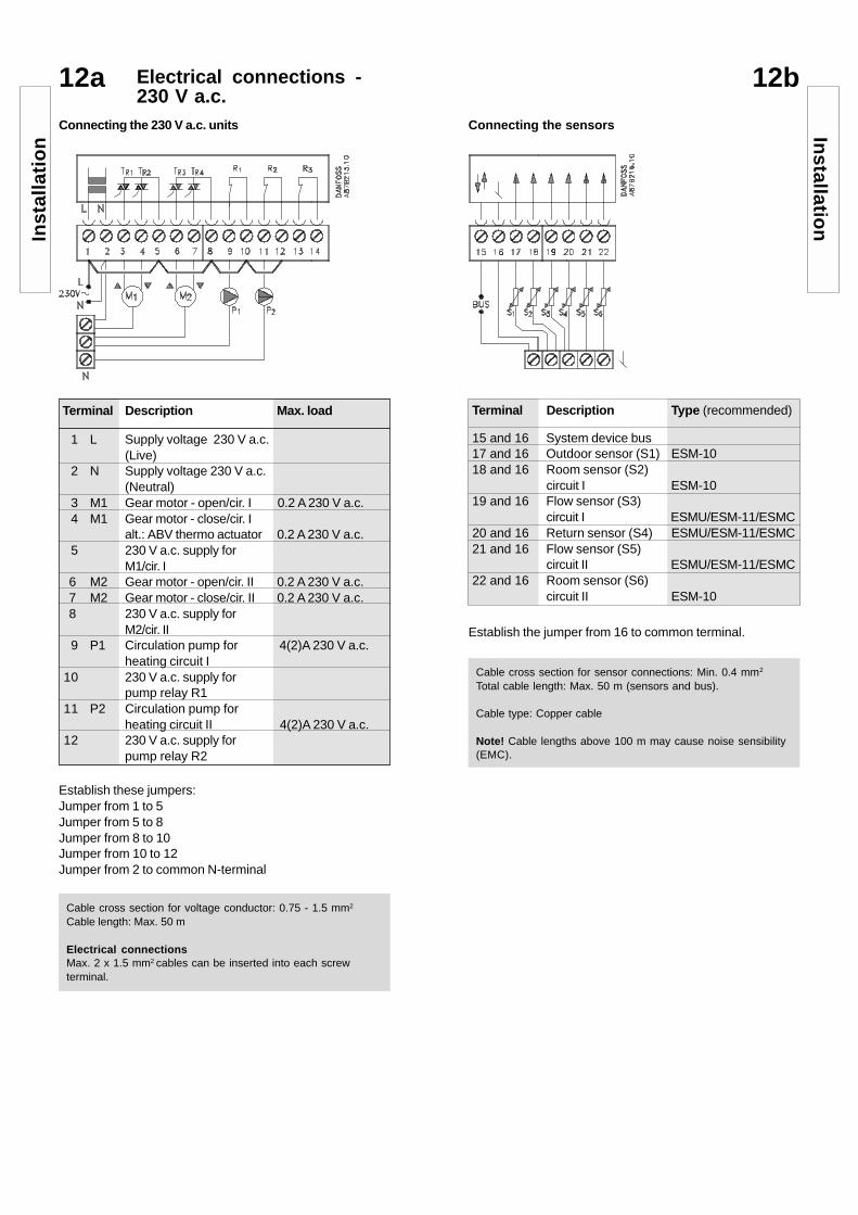
Connecting the sensorsConnecting the 230 V a.c. units
12a Electrical connections -230 V a.c.
Cable cross section for voltage conductor: 0.75 - 1.5 mm2
Cable length: Max. 50 m
Electrical connectionsMax. 2 x 1.5 mm2 cables can be inserted into each screwterminal.
Cable cross section for sensor connections: Min. 0.4 mm2
Total cable length: Max. 50 m (sensors and bus).
Cable type: Copper cable
Note! Cable lengths above 100 m may cause noise sensibility(EMC).
Establish these jumpers:Jumper from 1 to 5Jumper from 5 to 8Jumper from 8 to 10Jumper from 10 to 12Jumper from 2 to common N-terminal
Terminal Description Max. load
1 L Supply voltage 230 V a.c.(Live)
2 N Supply voltage 230 V a.c.(Neutral)
3 M1 Gear motor - open/cir. I 0.2 A 230 V a.c.4 M1 Gear motor - close/cir. I
alt.: ABV thermo actuator 0.2 A 230 V a.c.5 230 V a.c. supply for
M1/cir. I 6 M2 Gear motor - open/cir. II 0.2 A 230 V a.c. 7 M2 Gear motor - close/cir. II 0.2 A 230 V a.c. 8 230 V a.c. supply for
M2/cir. II9 P1 Circulation pump for 4(2)A 230 V a.c.
heating circuit I10 230 V a.c. supply for
pump relay R111 P2 Circulation pump for
heating circuit II 4(2)A 230 V a.c.12 230 V a.c. supply for
pump relay R2
Terminal Description Type (recommended)
15 and 16 System device bus17 and 16 Outdoor sensor (S1) ESM-1018 and 16 Room sensor (S2)
circuit I ESM-1019 and 16 Flow sensor (S3)
circuit I ESMU/ESM-11/ESMC20 and 16 Return sensor (S4) ESMU/ESM-11/ESMC21 and 16 Flow sensor (S5)
circuit II ESMU/ESM-11/ESMC22 and 16 Room sensor (S6)
circuit II ESM-10
Establish the jumper from 16 to common terminal.
Installatio
nIn
stal
lati
on
12b
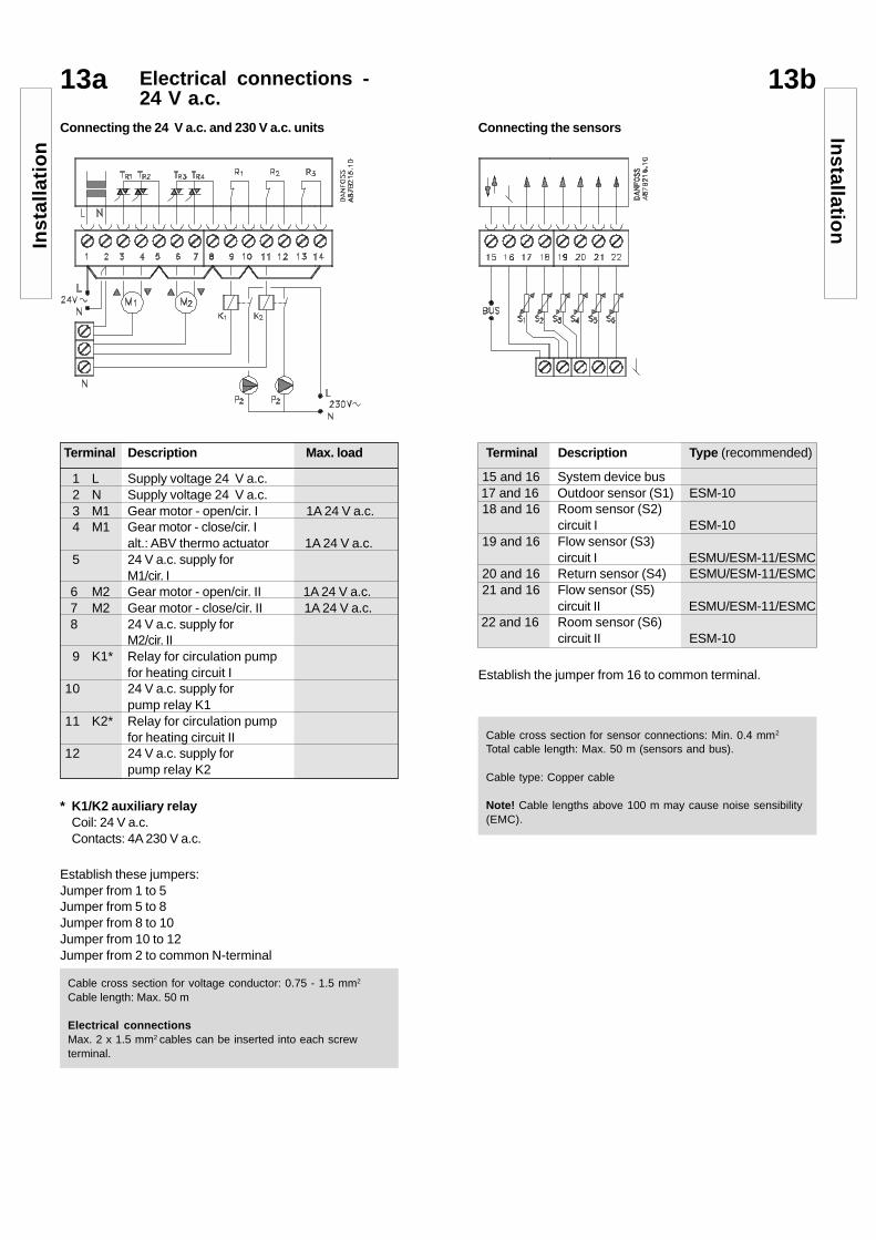
Connecting the sensorsConnecting the 24 V a.c. and 230 V a.c. units
13a Electrical connections -24 V a.c.
Establish the jumper from 16 to common terminal.
Establish these jumpers:Jumper from 1 to 5Jumper from 5 to 8Jumper from 8 to 10Jumper from 10 to 12Jumper from 2 to common N-terminal
Terminal Description Max. load
1 L Supply voltage 24 V a.c.2 N Supply voltage 24 V a.c.3 M1 Gear motor - open/cir. I 1A 24 V a.c.4 M1 Gear motor - close/cir. I
alt.: ABV thermo actuator 1A 24 V a.c.5 24 V a.c. supply for
M1/cir. I 6 M2 Gear motor - open/cir. II 1A 24 V a.c. 7 M2 Gear motor - close/cir. II 1A 24 V a.c. 8 24 V a.c. supply for
M2/cir. II9 K1* Relay for circulation pump
for heating circuit I10 24 V a.c. supply for
pump relay K111 K2* Relay for circulation pump
for heating circuit II12 24 V a.c. supply for
pump relay K2
Terminal Description Type (recommended)
15 and 16 System device bus 17 and 16 Outdoor sensor (S1) ESM-1018 and 16 Room sensor (S2)
circuit I ESM-1019 and 16 Flow sensor (S3)
circuit I ESMU/ESM-11/ESMC20 and 16 Return sensor (S4) ESMU/ESM-11/ESMC21 and 16 Flow sensor (S5)
circuit II ESMU/ESM-11/ESMC 22 and 16 Room sensor (S6)
circuit II ESM-10
Cable cross section for voltage conductor: 0.75 - 1.5 mm2
Cable length: Max. 50 m
Electrical connectionsMax. 2 x 1.5 mm2 cables can be inserted into each screwterminal.
Cable cross section for sensor connections: Min. 0.4 mm2
Total cable length: Max. 50 m (sensors and bus).
Cable type: Copper cable
Note! Cable lengths above 100 m may cause noise sensibility(EMC).
* K1/K2 auxiliary relayCoil: 24 V a.c.Contacts: 4A 230 V a.c.
Installatio
nIn
stal
lati
on
13b
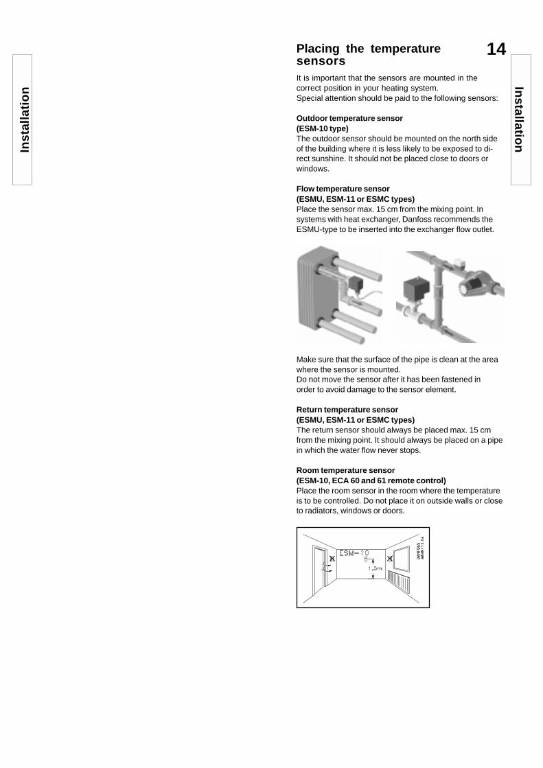
14Placing the temperaturesensorsIt is important that the sensors are mounted in thecorrect position in your heating system.Special attention should be paid to the following sensors:
Outdoor temperature sensor(ESM-10 type)The outdoor sensor should be mounted on the north sideof the building where it is less likely to be exposed to di-rect sunshine. It should not be placed close to doors orwindows.
Flow temperature sensor(ESMU, ESM-11 or ESMC types)Place the sensor max. 15 cm from the mixing point. Insystems with heat exchanger, Danfoss recommends theESMU-type to be inserted into the exchanger flow outlet.
Make sure that the surface of the pipe is clean at the areawhere the sensor is mounted.Do not move the sensor after it has been fastened inorder to avoid damage to the sensor element.
Return temperature sensor(ESMU, ESM-11 or ESMC types)The return sensor should always be placed max. 15 cmfrom the mixing point. It should always be placed on a pipein which the water flow never stops.
Room temperature sensor(ESM-10, ECA 60 and 61 remote control)Place the room sensor in the room where the temperatureis to be controlled. Do not place it on outside walls or closeto radiators, windows or doors.
Inst
alla
tio
nIn
stallation
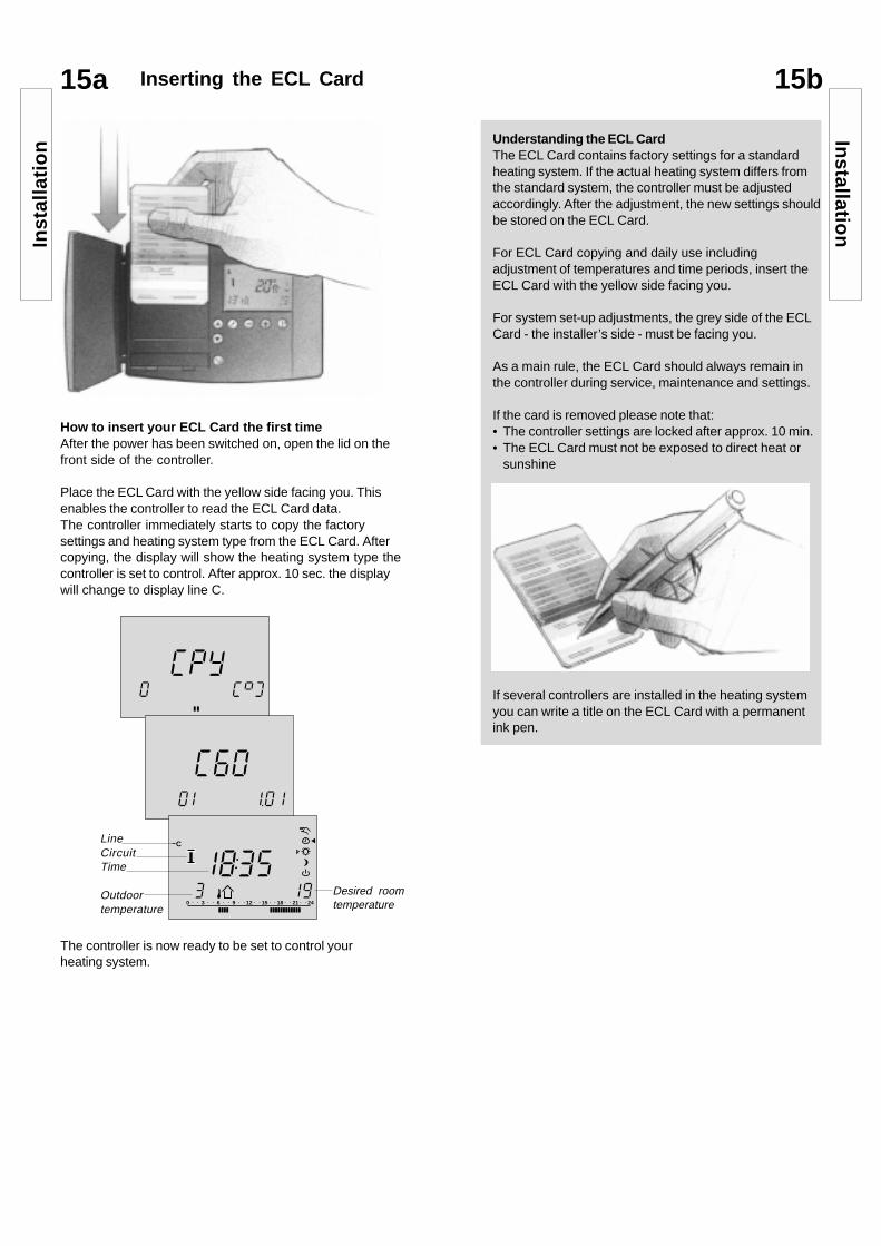
Understanding the ECL CardThe ECL Card contains factory settings for a standardheating system. If the actual heating system differs fromthe standard system, the controller must be adjustedaccordingly. After the adjustment, the new settings shouldbe stored on the ECL Card.
For ECL Card copying and daily use includingadjustment of temperatures and time periods, insert theECL Card with the yellow side facing you.
For system set-up adjustments, the grey side of the ECLCard - the installer’s side - must be facing you.
As a main rule, the ECL Card should always remain inthe controller during service, maintenance and settings.
If the card is removed please note that:• The controller settings are locked after approx. 10 min.• The ECL Card must not be exposed to direct heat or
sunshine
If several controllers are installed in the heating systemyou can write a title on the ECL Card with a permanentink pen.
LineCircuitTime
Outdoortemperature
Desired roomtemperature
CC 99
Y0
P
C100
061 1
80 3 6 9 12 15 18 21 24
1913
5C
3
15a Inserting the ECL Card
How to insert your ECL Card the first timeAfter the power has been switched on, open the lid on thefront side of the controller.
Place the ECL Card with the yellow side facing you. Thisenables the controller to read the ECL Card data.The controller immediately starts to copy the factorysettings and heating system type from the ECL Card. Aftercopying, the display will show the heating system type thecontroller is set to control. After approx. 10 sec. the displaywill change to display line C.
The controller is now ready to be set to control yourheating system.
Inst
alla
tio
nIn
stallation
15b

17Setting the time and date -Line A
In case of a power failure which lasts longer than 12 hours,the time and the date have to be set again.All other settings are stored as programmed.
Go to line A.
09
015 6019
5
A
3
Actual time
Month, dayYear
Use the shift button to switch between minutes,hours, year, month and day
Set the correct time and date
Use the yellow side of the ECL Card to enter the dayplan settings.See User’s Guide, section 4.
16 Adjusting the ECL Cardsettings
Update of the ECL Card after maintenance andserviceAll new settings can be stored on the ECL Card. Fordetails about copying, see section 34. Insert the ECLCard with the yellow side facing you.
CC 99
Y0
P
When the copying is finished display line C will appear
80 3 6 9 12 15 18 21 24
1913
5C
3
You can make other changes in the day plan, set timeand date or change settings (see User’s Guide).
General principlesWhen the controller is connected and operating you cancheck and adjust all or some of the basic settings on thegrey side of the ECL Card.
Use the arrow buttons to move from line to lineof the ECL Card, for example line 2:
Lineindicator
Settings tobe adjusted
Value in rangeindicator
Circuit2
0904
1 1
ON
2
ON
2
Use the minus/plus buttons to adjust thesettings.
In some displays more than one setting orvalue can be adjusted. Use the shift button toswitch between the possibilities.
The circuit selector shifts between circuit Iand II. You can adjust all settings and serviceparameters individually in both circuits, ie.circuit II.
Go to line 9 (bottom line)
Accept to copy as indicated. No other keys areactive.
Bas
ic s
et-u
pB
asic set-up
The greyside of theECL Card

19Manual control - Line B
Go to line B.
Shift to manual mode
Monitoring temperaturesand system units - Line B
18
Go to line B.
The activity of the motorized valve is shown as arrowsbelow the valve symbol. When the circulation pump isoperating, it is indicated as ON below the pump symbol.
If a sensor is not mounted or is disconnected, the displaywill indicate it as “- -”.
If the sensor is short-circuited, the display will indicate it as“- - - “.
If you are in doubt, remove the controller and check theohmic value between the relevant terminals.
5 036
B
1 1
ON
2
ON
2 Controlled units
State indicator
Return temperature
Flowtemperature
Push the shift button to see:- the calculated flow temperature- the return temperature set points
Relationship between temperature and ohmic value
-10 °C 961 Ohm 0 °C 1000 Ohm 10 °C 1039 Ohm 20 °C 1078 Ohm 30 °C 1117 Ohm 40 °C 1156 Ohm 50 °C 1195 Ohm 60 °C 1234 Ohm 70 °C 1273 Ohm
-50
800
900
1000
1100
1200
1300
1400
1500
1600
-25 0 25 50 75 100 125 150
Temperature
Ohm
5 036
B
1 1
ON
2
ON
2Controlledunits Controller mode
The circuit selector shifts between circuit I and II.
Bas
ic s
et-u
pB
asic set-up
The greyside of theECL Card
The greyside of theECL Card
The gear motor
opens or closes
the valve as long as the the relevant button ispressed.
The thermo actuator(according to version *)),
closes (NO) or opens (NC)
the valve as long as the relevant button ispressed.
*) NO - normally openNC - normally closed
Pumps are switched off or on when therelevant button is pressed.
Note!During manual operation, the pump motion is OFF.
1
11
1
ON
1
Check the activation direction of the motorized valve eitherby looking at it or by feeling whether the temperature of theactual pipe changes as expected.
This operation applies to both circuits. Press thebutton to select circuit II.
Select the unit you want to control. The selectedunit symbol will flash.
1

-20 -10 0 10 20-30
10
20
30
40
50
60
70
80
901,4 1,8
1,0
0,6
0,2
2,2
oC
oC
Floor heating systemsThis controller is factory set for radiator systems, which aretypically high flow temperature systems.To control floor heating systems, which are typically low flowtemperature systems, you need to change the heat curveaccording to your type of system.
Setting the heat curve -Line C
20a
Go to line C.The symbol for the slope of the heat curve willflash.
Make your adjustments.
Adjust the slope of the heat curve, if required.
If you want to adjust the parallel displacement ofthe heat curve, push the shift button. The symbolfor the parallel displacement will flash.
Basic set-u
p
8C
1
1 1
ON
2
ON
2
0
Slope
Displacement
Bas
ic s
et-u
p
The greyside of theECL Card
20b
SlopeCircuit Setting range Factory setting
I/II 0.2 ... 3.4 1.8
Parallel displacementCircuit Setting range Factory setting
l/II -9... +9 0SlopeCircuit Setting range Typical setting
I 0.2 ... 3.4 1.0
Parallel displacementCircuit Setting range Typical setting
I -9 ... +9 0
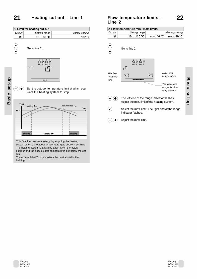
Flow temperature limits -Line 2
22
Go to line 2.
The left end of the range indicator flashes.Adjust the min. limit of the heating system.
Select the max. limit. The right end of the rangeindicator flashes.
Adjust the max. limit.
Heating cut-out - Line 121
81
1
1 1
ON
2
ON
2
Set the outdoor temperature limit at which youwant the heating system to stop.
Go to line 1.
2
0904
1 1
ON
2
ON
2
Max. flowtemperature
Min. flowtempera-ture
Temperaturerange for flowtemperature
This function can save energy by stopping the heatingsystem when the outdoor temperature gets above a set limit.The heating system is activated again when the actualoutdoor and the accumulated temperatures get below the setlimit.The accumulated Tout symbolises the heat stored in thebuilding.
18 ˚C
TempActual Tout Accumulated Tout
Time
Heating Heating off Heating
Bas
ic s
et-u
pB
asic set-up
The greyside of theECL Card
The greyside of theECL Card
2 Flow temperature min., max. limitsCircuit Setting range Factory setting
I/II 10 ... 110 °C min. 40 °C max. 90 °C
1 Limit for heating cut-outCircuit Setting range Factory setting
I/II 10 ... 30 °C 18 °C

Room temperatureinfluence - Line 3
23a
+
_
0
1 1
ON
2
0-4
3
3
ON
The room sensor in the reference room registersthe difference between the desired and the ac-tual room temperature. The flow temperature ref-erence will be corrected to eliminate this differ-ence.
B: Reference room controlUsed if your heating system is not equipped with radiatorthermostats and you select the room with room sensor as atemperature reference for the rest of the rooms.(However, should you have a few radiator thermostatsinstalled, make sure that they are fully open).
Set a positive value for min. influence and anegative value for max. influence.
+
_
set
Influence
Min. limitation
Max. limitation
TROOM
This section is only relevant if you have installed a roomsensor. There are two basic principles for control of theroom temperature influence:
A: Max. room temperature limitationUse this limitation if your heating system is fully equippedwith radiator thermostats and you also want to obtain amax. limitation of the room temperature. The controller willallow for free heat gains, i.e. solar radiation or heat from afire place, etc.
The max. influence determines how much theroom temperature should influence the flowtemperature.
Go to line 3.
Select the max. influence.The bar below the range indicator flashes in theright side of the display.
Adjust the max. influence.
TROOM
set
Influence
Max. limitation
Min.influence
Max.influence
ExampleThe actual room temperature is 2 degrees too high.The influence at max. limitation (right corner of the display) isset to -40.The influence at min. limitation (left corner of the display) isset to 0.Heat curve H is 1.8.Result:The flow temperature reference is changed by2 x -40 x 0.1 x H = -14.4 degrees.
ExampleThe actual room temperature is 2 degrees too low.The influence at max. limitation (right corner of the display) isset to 20.The influence at min. limitation(left corner of the display) is setto 20.Heat curve H is 1.8.Result:The flow temperature reference is changed by2 x 20 x 0.1 x H = 7.2 degrees.
The actual room temperature is 2 degrees too high.The influence at max. limitation (right corner of the display) isset to -35.The influence at min. limitation(left corner of the display) is setto 20.Heat curve H is 1.8.Result:The flow temperature reference is changed by2 x (-35) x 0.1 x H = -12.6 degrees.
Bas
ic s
et-u
pB
asic set-up
The greyside of theECL Card
23b
3 Room temperature influenceCircuit Setting range Factory setting
I/II 0 ... 99/-99 ... 0 min. 0 max. -40

Setting the PI-regulation -Line 4-7
26a
Go to line 4.
84
0
1 1
ON
2
ON
2
Setting to be adjustedLineindicator
Set the proportional band.A higher value will result in a stable, but slowregulation of the flow temperature.
Go to line 5.
Set a high integration time constant to obtain aslow but stable reaction to deviations.A low integration time constant will make thecontroller react fast but with less stability.
Go to line 6.
Set the running time of the motorized valveaccording to the example on the opposite page.This is the time it takes the valve to move fromclosed to fully open position.
Go to line 7.
Set the neutral zone to a high value if you canaccept a high variation in flow temperature.When the actual flow temperature is within theneutral zone, the controller does not activate themotorized valve.
Note! The valve is symmetrically around theflow reference value.
If you want to tune the PI-regulation precisely, you canuse the following method:• Set the integration time (line 5) to its max. value (999 sec.).• Decrease the value for the proportional band (Line 4) until
the system starts hunting with a constant amplitude (it mightbe necessary to force the system by setting an extremevalue).
• Find the critical time period on the temperature recording oruse a stop watch.
This time period will be characteristic for the system, and youcan evaluate the settings from this critical period.
Integration time = 0.85 x critical time periodProportional band = 2.2 x proportional band value in the
critical time period.
If the regulation seems to be too slow, you can decrease theproportional band value by 10%.
Note! Make sure there is a consumption when you set theparameters.
Time
Temp
Critical time period
How to calculate the running time of the motorized valve
The running time of the motorized valve is calculated using thefollowing methods:
Seated ValvesRunning time = Valve stroke (mm) x actuator speed (sec./mm)Example: 5.0 mm x 15 sec/mm = 75 sec.
Rotating ValvesRunning time = Turning degrees x actuator speed (sec./degr.)Example: 90 degrees x 2 = 180 sec.
VS2 15 3.0 AMV 100 90 270VS2 15...25, VM2 15...25, AMV(E)VB2 15...20 5.0 10, 20 15 75VS2 15...25, VM2 15...25,VB2 15...20 5.0 AMV(E) 30 3 15VM2 32, VB2 25 7.0 AMV(E) 20 15 105VM2 32, VB2 25 7.0 AMV(E) 30 3 21
Valve type Valve Actuator Actuator Runningstroke type speed time(mm) (sec./mm) (sec.)
Bas
ic s
et-u
pB
asic set-up
The greyside of theECL Card
26b
4 Proportional bandCircuit Setting range Factory setting
I/II 1 ... 250 K 80 K
5 Integration time constantCircuit Setting range Factory setting
I/II 5 ... 999 sec. 30 sec.
6 Running time of the motorized valveCircuit Setting range Factory setting
I/II 5 ... 250 sec. 35 sec.
7 Neutral zoneCircuit Setting range Factory setting
I/II 0 ... 9 K 3 K
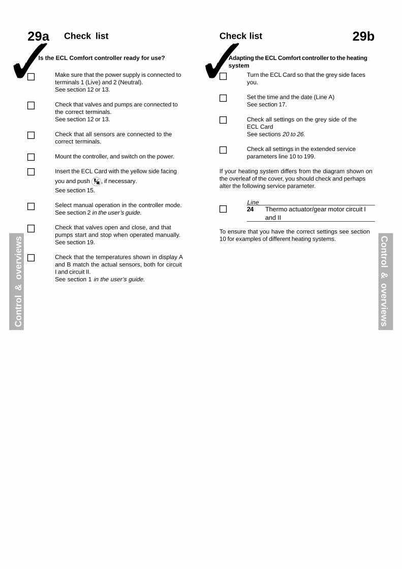
Adapting the ECL Comfort controller to the heatingsystem
29bCheck list
If your heating system differs from the diagram shown onthe overleaf of the cover, you should check and perhapsalter the following service parameter.
To ensure that you have the correct settings see section10 for examples of different heating systems.
✓ Turn the ECL Card so that the grey side facesyou.
Set the time and the date (Line A)See section 17.
Check all settings on the grey side of theECL CardSee sections 20 to 26.
Check all settings in the extended serviceparameters line 10 to 199.
29a Check list
✓ Is the ECL Comfort controller ready for use?
Make sure that the power supply is connected toterminals 1 (Live) and 2 (Neutral).See section 12 or 13.
Check that valves and pumps are connected tothe correct terminals.See section 12 or 13.
Check that all sensors are connected to thecorrect terminals.
Mount the controller, and switch on the power.
Insert the ECL Card with the yellow side facing
you and push , if necessary.
See section 15.
Select manual operation in the controller mode.See section 2 in the user’s guide.
Check that valves open and close, and thatpumps start and stop when operated manually.See section 19.
Check that the temperatures shown in display Aand B match the actual sensors, both for circuitI and circuit II.See section 1 in the user’s guide.
Co
ntr
ol
& o
verv
iew
s
24 Thermo actuator/gear motor circuit Iand II
Line
Co
ntro
l & o
verviews

ECL Card settings(circuit II: Heating)
30bECL Card settings(circuit I: Heating)
30a
A Time and date
B System information
C Heat curve
See sections 16 & 17
See sections 18 & 19
See section 20
Heat curve - Slope0.2 ... 3.4 1.8Set the slope of the heat curve,see section 20
Heat curve - Parallel displacement-9 ... +9 0KSet the parallel displacement of theheat curve, see section 20
1Limit for heating cut-out10 ... 30 °C 18 °CSave energy by stopping the heatingsystem when the outdoor temperature getsabove a certain limit, see section 21.
2Flow temperature min.-/max. limits10 ... 110 °C min. 40, max. 90 °CThe limits for min.- and max. flowtemperature, see section 22.
3Room temperature influence 0 ... +99/-99 ... 0 min. 0, max. -40The room temperature’s influence on theflow temperature control, see section 23.
4Proportional band1 ... 250 K 80 KSet the PI-regulation, see section 26.
5Integration time constant5 ... 999 sec. 30 sec.Set the PI-regulation, see section 26.
6Motor / valve running time5 ... 250 sec. 35 sec.Set the PI-regulation, see section 26.
7Neutral zone
0 ... 9 K 3 KSet the PI-regulation, see section 26.
Setting range Factory setting Your settings
A Time and date
B System information
C Heat curve
See sections 16 & 17
See sections 18 & 19
See section 20
Heat curve - Slope0.2 ... 3.4 1.8Set the slope of the heat curve,see section 20
Heat curve - Parallel displacement-9 ... +9 0KSet the parallel displacement of theheat curve, see section 20
1Limit for heating cut-out10 ... 30 °C 18 °CSave energy by stopping the heatingsystem when the outdoor temperature getsabove a certain limit, see section 21.
2Flow temperature min.-/max. limits10 ... 110 °C min. 40, max. 90 °CThe limits for min. - and max. flowtemperature, see section 22.
3Room temperature influence 0 ... +99/-99 ... 0 min. 0, max. -40The room temperature’s influence on theflow temperature control, see section 23.
4Proportional band1 ... 250 K 80 KSet the PI-regulation, see section 26.
5Integration time constant5 ... 999 sec. 30 sec.Set the PI-regulation, see section 26.
6Motor / valve running time5 ... 250 sec. 35 sec.Set the PI-regulation, see section 26.
7Neutral zone0 ... 9 K 3 KSet the PI-regulation, see section 26.
Co
ntr
ol
& o
verv
iew
s Co
ntro
l & o
verviews
Setting range Factory setting Your settings

10 Choice of time control unit0 ... 5 0
11 Reduced temperature dependenton outdoor temperatureOFF/-29 ... +10 °C -15 °C °C
12 Boost0 ... 99% 0% %
13 Reference ramping0 ... 99 min 0 min min
14 Optimising time constantOFF/10 ... 59 OFF
15 Adaptive function of roomtemperatureOFF/1 ... 30 OFF
17 Temperature reference feed backOFF/1 ... 20 OFF
20 Optimisation based on room/outdoor temperatureON/OFF OFF
21 Total stopON/OFF OFF
22 Pump motionON/OFF ON
23 Valve motionON/OFF OFF
24 Gear motor/thermo actuatorON/OFF ON
31 Return temperature limitation (X)-30 ... +15 °C +15 °C °C
32 Return temperature limitation (Y)10 ... 110 °C 40 °C °C
33 Return temperature limitation (X)-30 ... +15 °C -15 °C °C
34 Return temperature limitation (Y)10 ... 110 °C 60 °C °C
35 Return temperature influence - max-9.9 ... 0 ... +9.9 °C -2 °C °C
36 Return temperature influence - min-9.9 ... 0 ... 9.9 °C 0 °C °C
37 Adaptive function of return limitationOFF/1 ... 50 25
52 Closed valve/PI-regulationON/OFF OFF
141 Override input selectionOFF/1 ... 6 OFF
174 Motor protectionOFF/10...59 min OFF
196 Service pin - LONON/OFF OFF
197 LON resetON/OFF ON
10 Choice of time control unit0 ... 5 0
11 Reduced temperature dependenton outdoor temperatureOFF/-29 ... +10 °C -15 °C °C
12 Boost0 ... 99% 0% %
13 Reference ramping0 ... 99 min 0 min min
14 Optimising time constantOFF/10 ... 59 OFF
15 Adaptive function of roomtemperatureOFF/1 ... 30 OFF
20 Optimisation based on room/outdoor temperatureON/OFF OFF
21 Total stopON/OFF OFF
22 Pump motionON/OFF ON
23 Valve motionON/OFF OFF
24 Gear motor/thermo actuatorON/OFF ON
31 Return temperature limitation (X)-30 ... +15 °C +15 °C
32 Return temperature limitation (Y)10 ... 110 °C 40 °C °C
33 Return temperature limitation (X)-30 ... +15 °C -15 °C °C
34 Return temperature limitation (Y)10 ... 110 °C 60 °C °C
35 Return temperature influence - max-9.9 ... 0 ... 9.9 °C -2 °C °C
36 Return temperature influence - min-9.9 ... 0 ... 9.9 °C 0 °C °C
37 Adaptive function of return limitationOFF/1 ... 50 25 °C
52 Closed valve/PI-regulationON/OFF OFF
141 Override input selectionOFF/1 ... 6 OFF
174 Motor protectionOFF/10...59 min OFF
Service parameters
Circuit II (heating)Line Setting range Factory setting Your setting
Service parameters31aCircuit I (heating)
Line Setting range Factory seting Your setting
Circuit I (heating)Line Setting range Factory seting Your setting
198 Summer time changeON/OFF ON
199 Slave address0 ... 9 15
Co
ntr
ol
& o
verv
iew
s Co
ntro
l & o
verviews
31b

32bService parameters 10-11
Select between
The greyside of theECL Card
ECL Comfort controller - day plan for circuitRoom panel ECA 60 or remote controlECA 61 on address ARoom panel ECA 60 or remote controlECA 61 on address B
01
2
-29 to +10 °CThe setting of reduced temperature depends onthe outdoor temperature, when the outdoortemperature is above the set limit.The lower the outdoor temperature the less thetemperature reduction. When the outdoortemperature is below the set limit, there is notemperature reduction.
OFF: The reduced temperature setting will beconstant at all outdoor temperatures.
32a Adjusting the serviceparameters
In addition to the settings in line 1 to 7 on the greyside of the ECL Card, there is an extended servicemenu from line 10 and onwards.
When you have entered all your personal settings, turn theECL Card over so that the yellow side faces you.
If you want to copy the new settings to the ECL Card(recommended by Danfoss), see section 34.
Make a note of your new settings on the parameter list insection 31.
Push repeatedly to reach the linesnumbered 10 and onwards.
Linenumber
Value
Range indicator
001
Now you can move to any line of your choice.
Set the parameter value.
You can select any of the two circuits no matterwhat line you are in. You will not necessarily en-ter the same line number.See the service parameters in section 31.
100%
0%-20 -10-29 0 10 2015
Reduction
Outdoortemp. oC
Exten
ded
serviceE
xten
ded
se
rvic
e
11 Reduced temperature dependent on outdoor temperatureCircuit Setting range Factory setting
I/II OFF / -29 ... +10 °C -15 °CLimit of the outdoor temperature at which the reducedtemperature setting is switched off.
10 Choice of time control unitCircuit Setting range Factory setting
I/II 0 ... 5 0Dedicates the unit for the time control of the comfort andreduced temperature periods

The adaptive function will eliminate the differencebetween the required and the actual room temperature byintegrating the difference and adjusting the reference forthe flow temperature.
32dService parameters 14-15
OFF: The adaptive function is cancelled.1: The desired temperature is adapted
quickly.30: The desired temperature is adapted
slowly.
32c Service parameters 12-13
In order to avoid load peaks in the supply network, theflow temperature reference can be set to increase slowlyafter a period with reduced temperature. This causes thevalve to open slowly.
In order to shorten the heating-up period after a reducedtemperature period, the flow temperature can beincreased temporarily.If a room sensor is installed, the boost stops when theoptimising period is over or the room temperature hasbeen reached.
°C
Tref
Tref
Setting line 13 Time
Set the percentage at which you want the flowtemperature to be changed temporarily.
Set the opening time you want the valve to use.
OFF: No optimisation. The heating starts and stops atthe times set in the week plan.
Dimensioning temperature: The lowest outdoortemperature at which the heating system can securethe desired temperature.
41
25
2. digit (capacity of the heating system)
2. digit Dimensioning Capacity temperature
large..
normal..
small
-50 °C..
-25 °C..
-05 °C
0..5..
9
Adjust the optimising time constant. The valueconsists of a number of two digits. You can selectthe following values:11, 12, ..... 59.The two digits have the following meaning:
1. digit (system type and heat accumulation ofthe building)
12345
lightmediumheavymediumheavy
1. digit Heat accumulation System typeof the building
Radiatorsystem
Floor heatingsystem
Ext
end
ed
serv
ice E
xtend
ed
service
The greyside of theECL Card
The greyside of theECL Card
12 BoostCircuit Setting range Factory setting
I/II 0 ... 99% 0%Shortens the heating-up period by increasing the flowtemperature by the percentage you set.
13 Reference rampingCircuit Setting range Factory setting
I/II 0 ... 99 min 0The time in which the flow temperature increases slowly to avoidload peaks in the supply.
14 Optimising time constantCircuit Setting range Factory setting
I/II OFF / 10 ... 59 OFFOptimises the start and stop times for the reducedtemperature period to obtain the best comfort at the lowestenergy consumption.
15 Adaptive function of room temperatureCircuit Setting range Factory setting
I/II OFF / 1 ... 30 OFFControls how fast the room temperature adapts to thedesired temperature.

32fService parameter 21
Select total stop function.
ON: Total stop function is ON. At total stop theflow temperature reference is lowered to10 °C, and the minimum setting of theflow temperature limit of line 2 (seesection 22) is overruled in the reducedtemperature period.
OFF: No total stop
32e Service parameters 17-20
Select calculation method:
ON: Calculation based on room temperature(only if a room sensor is used).
OFF: Calculation based on outdoortemperature. Use this setting if you haveno room sensor.
OFF: The temperature reference in circuit I isnot influenced by any other controller.
1-20: The temperature reference in circuit Iwill always at least correspond with thevalue of the set number + the highesttemperature reference degree of anexternal controller.
Tref
(l)
Tref (ll)
Setting line 17
Time
°C
This function is used if circuit I is the main supply for othermixing circuits.
Ext
end
ed
serv
ice E
xtend
ed
service
The greyside of theECL Card
The greyside of theECL Card
21 Total stopCircuit Setting range Factory setting
I/II ON / OFF OFFDecide whether you want a total stop during reducedtemperature period.
17 Temperature reference feedbackCircuit Setting range Factory setting
I OFF / 1 ... 20 OFFThe temperature reference in heating circuit I can be influenced byanother external. The set number determines the influence of theflow temperature reference in circuit I or the reference signal by anyother connected controller.
20 Optimisation based on room/outdoor temperatureCircuit Setting range Factory setting
I/II ON / OFF OFFThe optimised start and stop time calculation can be based oneither the room temperature or on the outdoor temperature.
Time
TREF
Ref. temp.
TMIN
10 oC
Time
TREF
Ref. temp.
TMIN
10 oC

32g Service parameters 22-24
In district heating systems you have to switch off the valvemotion to avoid unnecessary heat consumption.
Set the anti-blocking function to ON or OFF.
ON: The pump is switched on for 1minuteevery third day.
OFF: The pump motion is switched off.
ON: The valve motion is switched on. Thevalve receives a signal to open and closeevery third day.
OFF: The valve motion is switched off.
Set the anti-blocking function to ON or OFF.
ON: Gear motor
OFF: Thermo actuator
Select actuator type:
Ext
end
ed
serv
ice E
xtend
ed
service
The greyside of theECL Card
23 Valve motionCircuit Setting range Factory setting
I/II ON / OFF OFFExercises the valve to avoid blocking in periods without heatdemand.
24 Gear motor / thermo actuatorCircuit Setting range Factory setting
I/II ON / OFF ONChoose the actuator type.
22 Pump motionCircuit Setting range Factory setting
I/II ON / OFF ONExercises the pump to avoid blocking in periods without heatdemand.
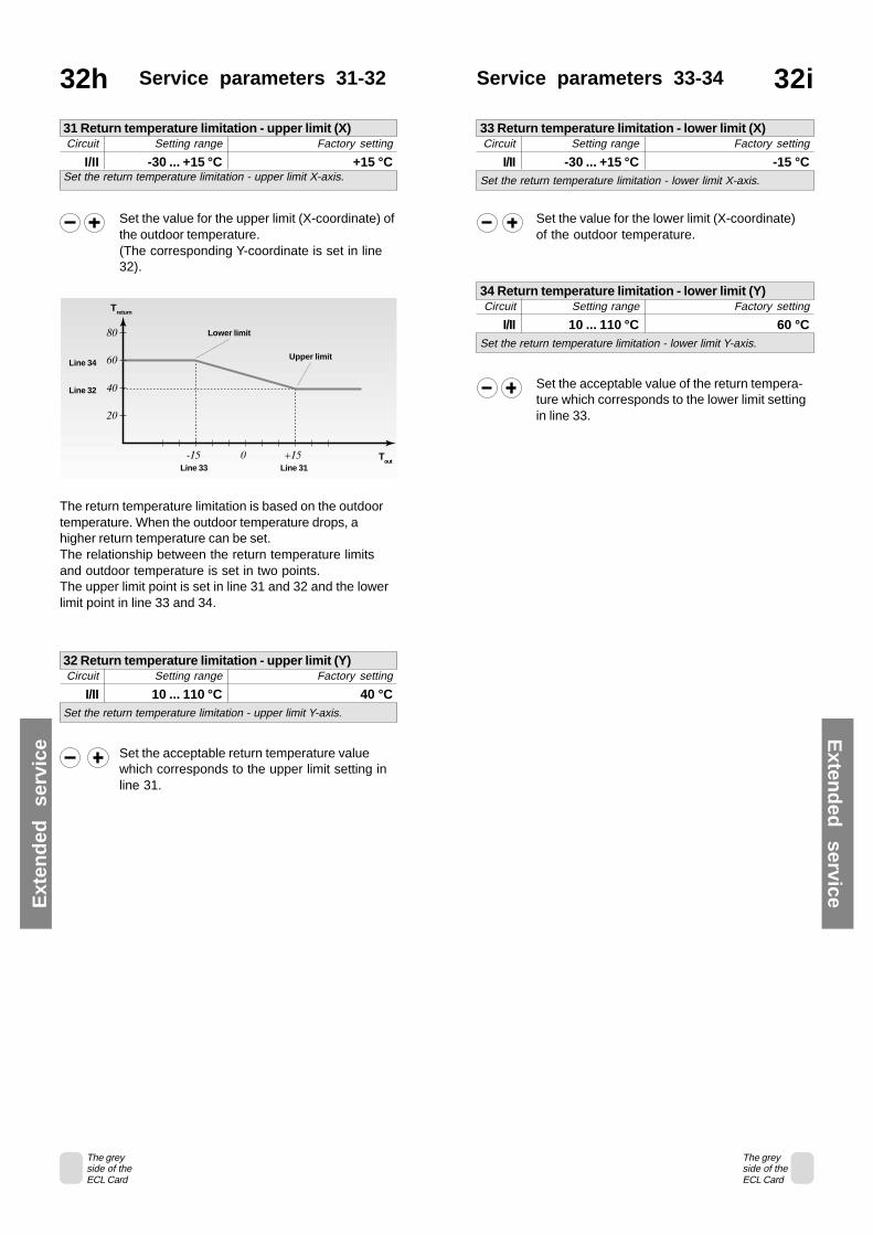
Set the value for the lower limit (X-coordinate)of the outdoor temperature.
Set the acceptable value of the return tempera-ture which corresponds to the lower limit settingin line 33.
Service parameters 33-34
Set the acceptable return temperature valuewhich corresponds to the upper limit setting inline 31.
32h Service parameters 31-32
Set the value for the upper limit (X-coordinate) ofthe outdoor temperature.(The corresponding Y-coordinate is set in line32).
The return temperature limitation is based on the outdoortemperature. When the outdoor temperature drops, ahigher return temperature can be set.The relationship between the return temperature limitsand outdoor temperature is set in two points.The upper limit point is set in line 31 and 32 and the lowerlimit point in line 33 and 34.
Treturn
Line 34
Line 32
Lower limit
Upper limit
Line 33 Line 31T
out
Ext
end
ed
serv
ice E
xtend
ed
service
32i
The greyside of theECL Card
The greyside of theECL Card
31 Return temperature limitation - upper limit (X)Circuit Setting range Factory setting
I/II -30 ... +15 °C +15 °CSet the return temperature limitation - upper limit X-axis.
32 Return temperature limitation - upper limit (Y)Circuit Setting range Factory setting
I/II 10 ... 110 °C 40 °CSet the return temperature limitation - upper limit Y-axis.
33 Return temperature limitation - lower limit (X)Circuit Setting range Factory setting
I/II -30 ... +15 °C -15 °CSet the return temperature limitation - lower limit X-axis.
34 Return temperature limitation - lower limit (Y) Circuit Setting range Factory setting
I/II 10 ... 110 °C 60 °CSet the return temperature limitation - lower limit Y-axis.

Service parameter 3632j Service parameter 35
Set the influence of the min. return temperaturelimitation.
If the displayed value does not equal 0, thefunction prevents the return temperature fromfalling below the limit set in line 30.
Influence higher than 0: The reference for theflow temperature is increased, when the returntemperature gets below the setting in line 30.
Influence lower than 0: The reference for the flowtemperature is decreased, when the returntemperature gets below the setting in line 30.
+
0
_ Min. limitation < 0
Influence
Return temp.Return limit
Min. limitation > 0
Set the influence of the max. return temperaturelimitation.
If the displayed value does not equal 0, thefunction prevents the return temperature fromgetting above the settings in lines 30-34.
Influence higher than 0: The reference for theflow temperature is increased, when the returntemperature gets above the settings in lines30-34.
Influence lower than 0: The reference for theflow temperature is decreased, when the returntemperature gets above the setting in lines30-34.
+
0
_ Max. limitation < 0
Influence
Return temp.Return limit
Max. limitation > 0
ExampleThe return limit is set to 50 degrees.The influence is set to -2.The actual return temperature is 2 degrees too high.Result:The flow temperature is lowered by 2 x-2 = -4 degrees.
Normally, the value set in line 35 is lower than 0 in districtheating systems and equals 0 in boiler systems.Normally, the setting in line 36 is 0 in district heating systemsand lower than 0 in boiler systems.With a normal return limitation you have to set a 0 in either line35 or 36.
ExampleReturn limit is set to 50 degrees.Influence is set to 2Actual return temperature is 2 degrees too low.Result:The flow temperature reference is increased with 2 x 2 = 4degrees.
Ext
end
ed
serv
ice E
xtend
ed
service
The greyside of theECL Card
The greyside of theECL Card
32k
35 Return temperature influence - max. limitationCircuit Setting range Factory setting
I/II -9.9 ... 0 ... 9.9 - 2How much the flow temperature reference should be influenced
36 Return temperature influence - min. limitationCircuit Setting range Factory setting
I/II -9.9 ... 0 ... +9.9 0How much the flow temperature should be influenced.

32l Service parameters 37-52
ON: The valve in the heating circuit is closedduring hot water service demand from amaster controller.
OFF: The flow temperature control remains un-changed during a hot water service de-mand from a master controller.
Note! Line 52 is set if this controller is a slave.
Select circuit.
Adjust the adaptive function of the returnlimitation. The setting will eliminate the differencebetween required and actual return temperatureby integrating the difference and adjusting thereference for the flow temperature.
In circuit I the settings mean:OFF: The heating curve will not be adjusted.1: The heating curve will be adjusted
quickly.50: The heating curve will be adjusted slowly.
In circuit II the settings mean:OFF: The charging temperature reference will
not be adjusted.1: The charging temperature will be ad-
justed quickly.50: The charging temperature will be ad-
justed slowly.
Ext
end
ed
serv
ice E
xtend
ed
service
The greyside of theECL Card
37 Adaptive function of return limitationCircuit Setting range Factory setting
I/II OFF / 1 ... 50 25Controls how fast the return temperature adapts to the desiredtemperature.
52 Closed valve/PI-regulationCircuit Setting range Factory setting
I/II ON/OFF OFFThe heating circuit can be closed, when the controllerfunctions as a slave controller.
Choose circuit I or II.
OFF: The controller is not overridden.
1 ... 6: Select a free sensor input S1... S6 for theoverride of the circuit in question.
Note:To avoid contact resistance, the use of the overridemodule ECA 9010 is recommended.
For an active override, you have to choose the mode“automatic operation”!
1 and 2 closed: 2 and 3 closed:Reduced temperature Comfort temperature
Connection example with ECA 9010
Connection example without ECA 9010
Closed switch: Closed switch:Reduced temperature Comfort temperature
Changeover switch:Reduced or comfort temperature
Each circuit can be overridden independently of eachother.
141 Override input selectionCircuit Setting range Factory setting
I/II OFF/1 ... 6 OFF/OFFChoose a free sensor input for the override of circuit I and/orcircuit II.
32mService parameter 141
The greyside of theECL Card

32oService parameters198-199
32n Service parameters174-197
ON: The controller’s built-in clock auto-matically changes +/- one hour on thestandardized days for summer timechangeover for Central Europe.
OFF: You change manually between summerand winter time by turning the clock onehour backward or forward.
Set the time-change function to be on or off:
The ECL Comfort controllers can be interconnected via theECL Comfort Bus to perform a larger system. One outdoorsensor can send the same information to all of them. Thecontroller, which is physically connected with the outdoorsensor, is the master of the entire system and getsautomatically the address 15. The other controllers in thesystem can be addressed with a slave number and receiveinformation from the outdoor sensor through the master.Only one address for one slave.
Assign addresses to the slaves:
0: The slave receives information aboutthe outdoor temperature and thesystem time.
1- 9: The slave receives information aboutthe outdoor temperature, the systemtime and control parameters. The slavesends the reference temperature to themaster.
15: The controller is master. The masteronly sends information about theoutdoor temperature and the systemtime. The master receives referencetemperature values from slaves withaddresses 1-9. Cannot be set.
Ext
end
ed
serv
ice E
xtend
ed
service
OFF: Motor protection is turned off
10...59: Motor protection is turned on. When aload change occurs, motor protectionis automatically disabled and will bereactivated when hunting is detectedagain.The disabling period can be set to 10-59 minutes.A high value should be used forinstallations with many consumers andvice versa.
Set the motor protection function to be on or off:
The greyside of theECL Card
The greyside of theECL Card
174 Motor protectionCircuit Setting range Factory setting
I/II OFF/10...59 min. OFFPrevents the acutator from hunting when the load in the heatingcircuit is very low. This stabilization increases the lifetime of theinvolved components.
196 Service pin - LONCircuit Setting range Factory setting
I ON/OFF OFFThis setting is only used in connection with communication (seethe documentation for the used communication unit).
197 LON resetCircuit Setting range Factory setting
I ON/OFF ONThis setting is only used in connection with communication (seethe documentation for the used communication unit).
198 Summer time changeCircuit Setting range Factory setting
I ON/OFF ONChoose whether you want the change to summer-/winter time tobe automatic or manual.
199 Slave addressCircuit Setting range Factory setting
I 0 ... 9 15The settings are relevant when more controllers are working inthe same system.
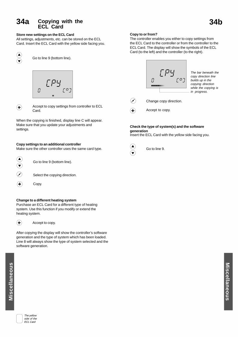
Go to line 9.
Check the type of system(s) and the softwaregenerationInsert the ECL Card with the yellow side facing you.
Copying with theECL Card
34a
Store new settings on the ECL CardAll settings, adjustments, etc. can be stored on the ECLCard. Insert the ECL Card with the yellow side facing you.
When the copying is finished, display line C will appear.Make sure that you update your adjustments andsettings.
CC 99
Y0
P
Go to line 9 (bottom line).
After copying the display will show the controller’s softwaregeneration and the type of system which has been loaded.Line 8 will always show the type of system selected and thesoftware generation.
Change to a different heating systemPurchase an ECL Card for a different type of heatingsystem. Use this function if you modify or extend theheating system.
Accept to copy.
Accept to copy settings from controller to ECLCard.
Copy settings to an additional controllerMake sure the other controller uses the same card type.
Go to line 9 (bottom line).
Select the copying direction.
Copy.
Copy to or from?The controller enables you either to copy settings fromthe ECL Card to the controller or from the controller to theECL Card. The display will show the symbols of the ECLCard (to the left) and the controller (to the right).
The bar beneath thecopy direction linebuilds up in thecopying directionwhile the copying isin progress.
CC 99
Y0
P
Change copy direction.
Accept to copy.
Mis
cell
aneo
us M
iscellaneo
us
The yellowside of theECL Card
34b

Definitions7a
Reduced temperatureTemperature maintained in the heating/hot water circuitduring setback periods.
Return temperatureTemperature measured in the return pipe.
Room sensorTemperature sensor placed in the room where the tem-perature is to be controlled. The sensor is based on the Pt1000 Ohm type.
Room temperatureTemperature measured by the room sensor. The room tem-perature can be controlled only when a sensor is installed.
State indicatorWhite arrow to the left of the symbols in the controller mode.The white arrow indicates the present state (comfort or re-duced temperature period) when the controller is in auto-matic mode (the clock symbol).
Time barBars representing periods with comfort temperature. Thebar is divided in half hour sections.
Time lineBar with numbers representing the hours in the lower partof the display.
Weather compensationFacility enabling the controller to take outdoor weatherconditions into consideration for heat control. Weathercompensation is based on a user-defined heat curve whichdetermines the flow temperature at varying outdoortemperatures.
Actual flow temperatureTemperature measured in the flow at any time.
Comfort periodA period of the day where comfort temperature isselected.
Comfort temperatureTemperature maintained in the heating or hot watercircuits during comfort periods. Normally during daytime.
Controller mode indicatorBlack arrow to the right of the symbols indicating thepresent mode selected.
Day planSchedule for different periods with comfort and reducedtemperatures. The day plan can be made individually foreach day and may consist of up to 3 comfort periods perday.
Desired temperatureTemperature which is set as the desired roomtemperature. The temperature can be controlled only if aroom sensor is installed. If no sensor is installed, thedesired temperature is only an expression for a possibleobtainable room temperature, meaning that the roomtemperature is controlled by radiator thermostats/valves.
Factory settingsSettings stored on the ECL Card to simplify the set up ofyour controller the first time.
Flow temperature referenceTemperature calculated by the controller on basis of theoutdoor temperature and influences from the room- and/orreturn sensors. This temperature is used as a set point for thecontrol.
Function selectorFacility making it possible to override the mode of the con-troller. Each circuit can be overriddden individually.
Heating circuitThe circuit for heating the room/building.
Optimising systemChangeover time between two programmedtemperature periods. The controller automatically controlsthe flow temperature in order to reach the comfort tempera-ture at the set time.
Pt 1000 Ohm sensorAll sensors used with the ECL Comfort controller are basedon the Pt1000 Ohm type. The resistance is 1000 Ohm at 0degrees and it changes with 3.9 degrees.
7b
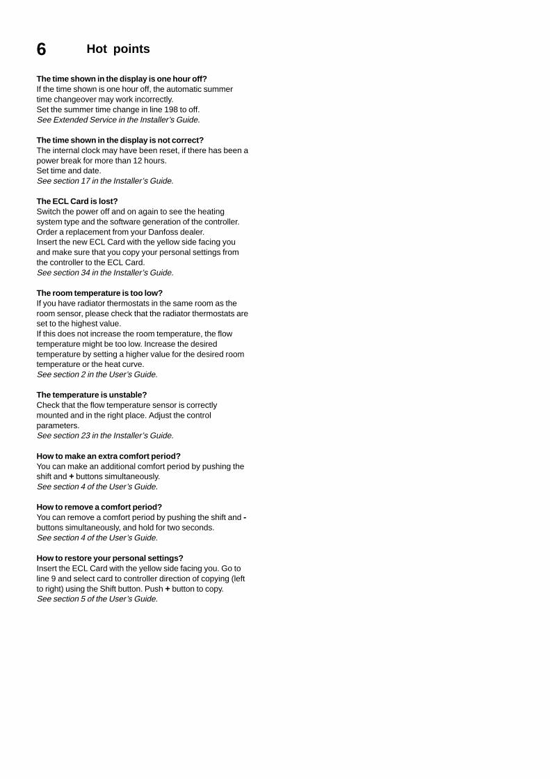
6 Hot points
The time shown in the display is one hour off?If the time shown is one hour off, the automatic summertime changeover may work incorrectly.Set the summer time change in line 198 to off.See Extended Service in the Installer’s Guide.
The time shown in the display is not correct?The internal clock may have been reset, if there has been apower break for more than 12 hours.Set time and date.See section 17 in the Installer’s Guide.
The ECL Card is lost?Switch the power off and on again to see the heatingsystem type and the software generation of the controller.Order a replacement from your Danfoss dealer.Insert the new ECL Card with the yellow side facing youand make sure that you copy your personal settings fromthe controller to the ECL Card.See section 34 in the Installer’s Guide.
The room temperature is too low?If you have radiator thermostats in the same room as theroom sensor, please check that the radiator thermostats areset to the highest value.If this does not increase the room temperature, the flowtemperature might be too low. Increase the desiredtemperature by setting a higher value for the desired roomtemperature or the heat curve.See section 2 in the User’s Guide.
The temperature is unstable?Check that the flow temperature sensor is correctlymounted and in the right place. Adjust the controlparameters.See section 23 in the Installer’s Guide.
How to make an extra comfort period?You can make an additional comfort period by pushing theshift and + buttons simultaneously.See section 4 of the User’s Guide.
How to remove a comfort period?You can remove a comfort period by pushing the shift and -buttons simultaneously, and hold for two seconds.See section 4 of the User’s Guide.
How to restore your personal settings?Insert the ECL Card with the yellow side facing you. Go toline 9 and select card to controller direction of copying (leftto right) using the Shift button. Push + button to copy.See section 5 of the User’s Guide.
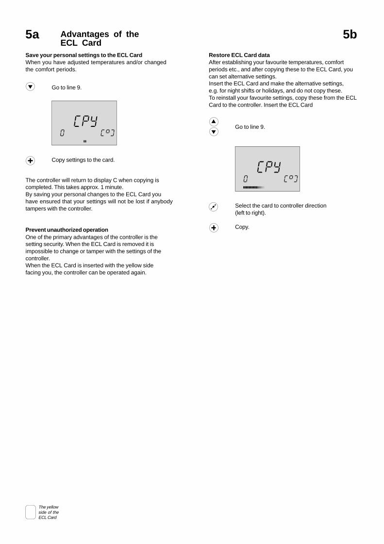
Restore ECL Card dataAfter establishing your favourite temperatures, comfortperiods etc., and after copying these to the ECL Card, youcan set alternative settings.Insert the ECL Card and make the alternative settings,e.g. for night shifts or holidays, and do not copy these.To reinstall your favourite settings, copy these from the ECLCard to the controller. Insert the ECL Card
CC 99
Y0
P
Go to line 9.
Select the card to controller direction(left to right).
Copy.
Advantages of theECL Card
5a
Save your personal settings to the ECL CardWhen you have adjusted temperatures and/or changedthe comfort periods.
CC 99
Y0
P
Go to line 9.
Copy settings to the card.
The controller will return to display C when copying iscompleted. This takes approx. 1 minute.By saving your personal changes to the ECL Card youhave ensured that your settings will not be lost if anybodytampers with the controller.
Prevent unauthorized operationOne of the primary advantages of the controller is thesetting security. When the ECL Card is removed it isimpossible to change or tamper with the settings of thecontroller.When the ECL Card is inserted with the yellow sidefacing you, the controller can be operated again.
The yellowside of theECL Card
5b
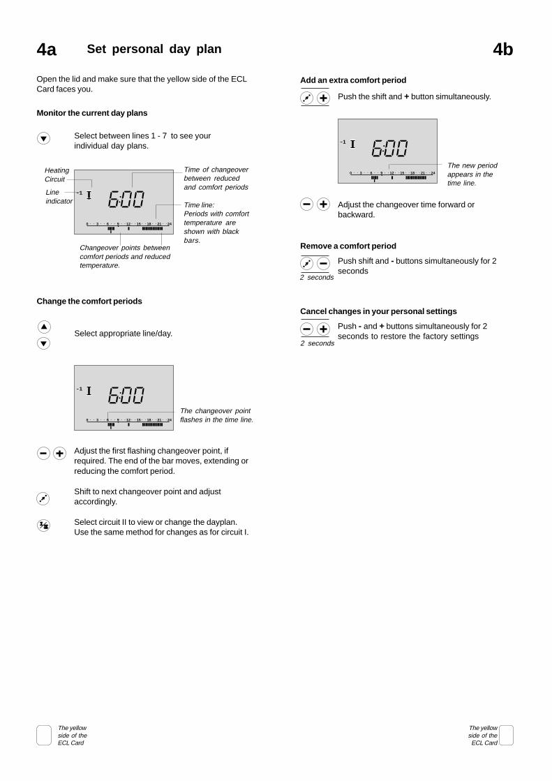
Add an extra comfort period
60 3 6 9 12 15 18 21 24
01
0The new periodappears in thetime line.
Adjust the changeover time forward orbackward.
Push the shift and + button simultaneously.
Remove a comfort period
Push shift and - buttons simultaneously for 2seconds
Cancel changes in your personal settings
Push - and + buttons simultaneously for 2seconds to restore the factory settings
2 seconds
Set personal day plan4a
Open the lid and make sure that the yellow side of the ECLCard faces you.
The changeover pointflashes in the time line.
60 3 6 9 12 15 18 21 24
01
0
Monitor the current day plans
Select between lines 1 - 7 to see yourindividual day plans.
Adjust the first flashing changeover point, ifrequired. The end of the bar moves, extending orreducing the comfort period.
Shift to next changeover point and adjustaccordingly.
Select circuit II to view or change the dayplan.Use the same method for changes as for circuit I.
Change the comfort periods
Select appropriate line/day.
60 3 6 9 12 15 18 21 24
01
0
Time of changeoverbetween reducedand comfort periods
Time line:Periods with comforttemperature areshown with blackbars.
HeatingCircuit
Changeover points betweencomfort periods and reducedtemperature.
Lineindicator
The yellowside of theECL Card
The yellowside of theECL Card
4b
2 seconds
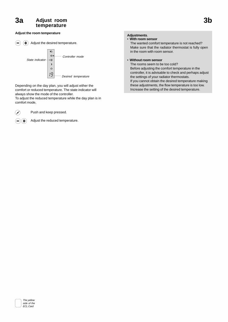
Adjustments.• With room sensor
The wanted comfort temperature is not reached?Make sure that the radiator thermostat is fully openin the room with room sensor.
• Without room sensorThe rooms seem to be too cold?Before adjusting the comfort temperature in thecontroller, it is advisable to check and perhaps adjustthe settings of your radiator thermostats.If you cannot obtain the desired temperature makingthese adjustments, the flow temperature is too low.Increase the setting of the desired temperature.
3a Adjust roomtemperature
Depending on the day plan, you will adjust either thecomfort or reduced temperature. The state indicator willalways show the mode of the controller.To adjust the reduced temperature while the day plan is incomfort mode,
Adjust the room temperature
Adjust the desired temperature.
Push and keep pressed.
Adjust the reduced temperature.
91 Desired temperature
State indicatorController mode
The yellowside of theECL Card
3b
2Select controller mode1 Choose favouritedisplay
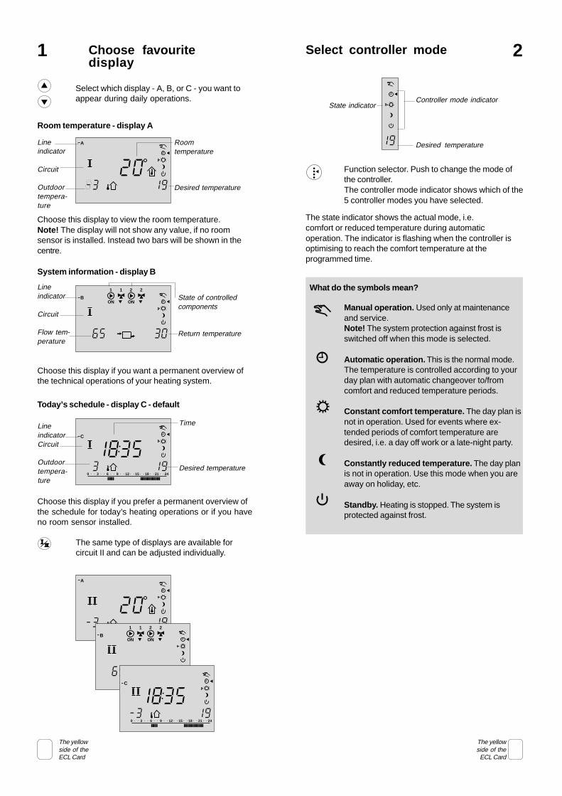
Choose this display if you prefer a permanent overview ofthe schedule for today’s heating operations or if you haveno room sensor installed.
Choose this display if you want a permanent overview ofthe technical operations of your heating system.
Room temperature - display A
Choose this display to view the room temperature.Note! The display will not show any value, if no roomsensor is installed. Instead two bars will be shown in thecentre.
Select which display - A, B, or C - you want toappear during daily operations.
913
208
A Roomtemperature
Desired temperature
Lineindicator
Circuit
Outdoortempera-ture
5 036
B
1 1
ON
2
ON
2
System information - display B
State of controlledcomponents
Return temperature
Lineindicator
Circuit
Flow tem-perature
80 3 6 9 12 15 18 21 24
1913
5C
3
Today’s schedule - display C - default
LineindicatorCircuit
Outdoortempera-ture
Time
Desired temperature
The same type of displays are available forcircuit II and can be adjusted individually.
913
20-
A
5 036
B
1 1
ON
2
ON
2
The state indicator shows the actual mode, i.e.comfort or reduced temperature during automaticoperation. The indicator is flashing when the controller isoptimising to reach the comfort temperature at theprogrammed time.
91
Controller mode indicator
Desired temperature
State indicator
Manual operation. Used only at maintenanceand service.Note! The system protection against frost isswitched off when this mode is selected.
Automatic operation. This is the normal mode.The temperature is controlled according to yourday plan with automatic changeover to/fromcomfort and reduced temperature periods.
Constant comfort temperature. The day plan isnot in operation. Used for events where ex-tended periods of comfort temperature aredesired, i.e. a day off work or a late-night party.
Constantly reduced temperature. The day planis not in operation. Use this mode when you areaway on holiday, etc.
Standby. Heating is stopped. The system isprotected against frost.
What do the symbols mean?
Function selector. Push to change the mode ofthe controller.The controller mode indicator shows which of the5 controller modes you have selected.
80 3 6 9 12 15 18 21 24
1913
5-
C
3
The yellowside of theECL Card
The yellowside of theECL Card
Save energy - save money - improve yourcomfort temperature
The ECL Comfort controller is designed by Danfoss for theautomatic temperature control of heating systems.The advantages of the ECL Comfort controller system arebased on the security of your heating control and theoptimum use of energy resources.Seasonal changes and variations in outdoor temperaturesare monitored by the control system.Reduced temperature periods and low energyconsumption while you are out or asleep save heatingcosts.The temperature programming provides comfort and theautomatic pump motion program protects againstblocking.The ECL Comfort controller meets your heating needsyou have stored as settings on the yellow ECL Card.These settings can only be changed if the ECL Card isinserted into the controller: A guarantee for safe andcontinuous operation.
Operating the ECL Comfort controllerWhen operating the controller it is advisable to keep thelid open in order to view the entire display.During operation the ECL Card must be inserted with theyellow side facing you.The yellow ECL Card is simple and easy to understand.The ECL Card is divided vertically for two circuits.Horizontally the ECL Card is divided into lines thatrepresent the different control and programming optionsfor the two circuits. Each line is shown in the display ofthe controller, which gives you an instant overview of theoperation, settings etc.
How to use the ECL GuideThis guide provides you with an easy instruction for theECL Comfort controller.The Installer’s Guide, the grey section (turn the guideover), sections 10 to 34, contains the complete list of factorysettings and various detailed adjustments that ensure anefficient and continuous operation of your heating system.This guide contains no page numbers. Use the Table ofContents to find the number of the section you wish toread.