c.5 geology, soils, and paleontology
TRANSCRIPT
Antelope Transmission Project, Segments 2 & 3 C.5 GEOLOGY, SOILS, AND PALEONTOLOGY
Final EIR C.5-1 December 2006
C.5 Geology, Soils, and Paleontology This section addresses the environmental setting and impacts related to the construction and operation of the proposed Project and alternatives involving the issues of geologic and seismic hazards, and paleontology. The primary reason to define geologic and seismic hazards is to protect structures from physical damage and to minimize injury/death of people due to structure damage or collapse. Section C.5.1 provides a summary of existing geological, soil, and paleontological conditions present along the alignment of SCE’s Antelope Transmission Project and associated geologic and seismic hazards. Applicable regulations, plans, and standards are listed in Section C.5.2. Potential impacts and mitigation measures for the proposed Project are presented in C.5.5; and alternatives are discussed in Sections C.5.6 through C.5.11.
C.5.1 Environmental Setting Baseline geologic, seismic, soils, and paleontological information for the proposed Project and surrounding area were collected from literature, GIS data, and online materials. All sources used for the purposes of characterizing baseline conditions and conducting this analysis are referenced as appropriate. The literature and data review was supplemented by a brief field reconnaissance of the proposed alignment (Aspen, 2006). The literature review and field reconnaissance focused on the identification of specific geologic hazards and paleontologic resources. The environmental setting for the Study Area is discussed generally by Project segment in the following sections; the segments are divided as follows: Segment 3 - from Mile S3-0.0 to Mile S3-35.2, beginning at the proposed Substation Two site and traveling south to Substation One and on to Antelope Substation; and Segment 2 - from Mile S2-0.0 to Mile S2-21.6, starting at Antelope Substation and traveling south to Vincent Substation. Segment 2 also includes two route options, known as Options A and B. Option A deviates from the proposed Project at Mile S2-5.7, travels 2.1 miles east of and parallel to the existing utility corridor, and reconnects with the proposed Project at approximately Mile S2-7.7. Option B deviates from the proposed Project at Mile S2-8.1, and travels 3.1 miles southeast along the existing utility corridor, and would reconnect with the proposed Project at approximately Mile S2-14.9.
C.5.1.1 Physiography
Segment 3 traverses two geographic areas with distinctly differing physiographic features: the Antelope Valley and the foothills of the Tehachapi Mountains. The Antelope Valley consists of approximately 1,200 square miles of elevated desert terrain, located along the western edge of the Mojave Desert with an average elevation of 2,500 feet. The Tehachapi Mountains are an east-west trending mountain range at the southern end of the Sierra Nevada which separates the Great Valley from the Mojave Desert and reaches elevations of up to 6,934 feet. Elevations along Segment 3 range from a high of approximately 5,000 feet in the Tehachapi Mountains to a low of approximately 2,470 at the Antelope Substation. The Substation Two site is approximately 4,100 feet above mean sea level (msl) and the Substation One site is approximately 3,400 feet above msl. Elevations were determined using USGS 7½ minute quadrangles from 3-D TopoQuads software (Delorme, 1999).
Segment 2 traverses three distinct geographic areas: the Antelope Valley, the Leona Valley (including the San Andreas Rift Zone), and the Sierra Pelona Mountains (including Soledad Pass). The Antelope Valley is described above. The Leona Valley is a small, northwest-southeast trending longitudinal valley formed by movement on multiple overlapping strands of the San Andreas Fault in the San Andreas Rift Zone. Within the Project area, the Leona Valley is bounded on the northeast by Portal and Ritter Ridges and on the southwest by foothills of the Sierra Pelona. Segment 2 crosses Soledad Pass just northeast of the upper end of Soledad Canyon. Soledad Pass is a saddle between the San Gabriel Mountains on the south and the Sierra Pelona on the
Antelope Transmission Project, Segments 2 & 3 C.5 GEOLOGY, SOILS, AND PALEONTOLOGY
December 2006 C.5-2 Final EIR
north. It also separates the Santa Clara River drainage to the west from the Mojave Desert to the east. The Sierra Pelona Mountains are a small northwest-southeast trending mountain range within the central Transverse Ranges. Elevations along the Segment 2 alignment range from about 2,470 feet at the Antelope Substation to approximately 4,470 feet above msl in the Sierra Pelona Mountains near where the alignment crosses just north of Ritter Canyon. The Vincent Substation is located at an elevation of approximately 3,250 feet above msl.
C.5.1.2 Geologic Conditions and Hazards
Geologic Setting
Segment 3 of the proposed transmission line crosses two areas of distinctive geologic character and province: the Antelope Valley and the Tehachapi Mountains. Segment 2 of the proposed transmission line crosses five areas of distinctive geologic character and province: the San Gabriel Mountains, the Soledad Basin, the Sierra Pelona Mountains, the San Andreas Rift Zone, and the Antelope Valley. The regional geology of the Project area along Segments 3 and 2 is depicted on Figures C.5-1 and C.5-2, respectively (all figures are at the end of this section).
Tehachapi Mountains. The Tehachapi Mountains are an east-west trending mountain range at the southern end of the Sierra Nevada which separates the Great Valley from the Mojave Desert. The Tehachapi Mountains have been sheared into this east-west trend by left-lateral fault movement of the Garlock fault which runs near the southern boundary of the range. Segment 3 starts at the Substation Two site in the Tehachapi Valley, which is a flat-floored alluvial valley within the Tehachapi Mountains covered by Holocene Alluvium and Pleistocene Older Alluvium. Segment 3 then crosses the Tehachapi Mountains, which are primarily composed of Mesozoic Quartz monzonite with local lenses of hornblende diorite in the Project vicinity. Beyond the southern edge of the Tehachapi Mountains, Segment 3 crosses into the northern end of the Antelope Valley.
Antelope Valley. The Antelope Valley consists of approximately 1,200 square miles of elevated desert terrain, located along the western edge of the Mojave Desert and is primarily an alluviated desert plain containing bedrock hills and low mountains. The rocks of the Antelope Valley are characterized by relatively flat-lying topography and valley fill deposits. Along Segments 2 and 3, the Antelope Valley is covered primarily by alluvial deposits of Quaternary age: Holocene Alluvium and Pleistocene Older Alluvium. The Holocene alluvial deposits consist of slightly dissected alluvial fan deposits of gravel, sand and clay. The Older Alluvium is located primarily near the margins of the Antelope Valley at the flanks of the Sierra Pelona and Tehachapi Mountains and consists of weakly consolidated, uplifted and moderately to severely dissected alluvial fan and terrace deposits composed primarily of sand and gravel (Dibblee, 1963 and 1997). Both the Antelope Substation and the Substation One site are located on Holocene Alluvial deposits.
San Andreas Rift Zone. In the Project area, the San Andreas Fault lies within a linear, trough-like valley called the San Andreas Rift Zone. The Rift Zone in the Project area consists of several anastomosing fault segments (i.e., interlacing faults), which along with the presence of Amargosa and Anaverde Creeks, has widened the zone into two valleys, the Lenore Valley and the Anaverde Valley, which are separated by fault bounded ridges. Holocene Alluvium, Pleistocene Older Alluvium, and the non-marine Pliocene Anaverde Formation underlie the both valleys. Exposed among interlacing fault strands within the San Andreas Fault Zone are several members of the Anaverde Formation: the sandstone, clay shale, and breccia members (CGS, 2006; Dibblee, 1997). The sandstone member is a medium-to thick-bedded, locally massive, fine- to coarse-grained, locally pebbly material with local thin silty interbeds. The clay shale member is a thin-bedded, sandy, silty, locally very gypsiferous clay shale with interbedded siltstone and sandstone layers. The breccia member
Antelope Transmission Project, Segments 2 & 3 C.5 GEOLOGY, SOILS, AND PALEONTOLOGY
Final EIR C.5-3 December 2006
is a distinctive, reddish to dark gray, massive, pervasively sheared sedimentary breccia with angular clasts of hornblende diorite. The bedding within the Anaverde Formation members mostly parallel the bounding faults, and has steep to vertical dips (CGS, 2006). The Segment 2 alignment crosses both Ritter and Portal Ridges, both comprised primarily of Pelona Schist on the eastern side of the Rift zone, before crossing the Rift Zone in a fairly narrow area between Ritter Ridge and the Sierra Pelona. Within the Rift Zone, the alignment crosses several strands of the San Andreas fault, Holocene and Older Alluvial deposits, and outcrops of the sandstone member of the Anaverde Formation. Option A is located along the slopes of both Portal and Ritter Ridges, just upslope and northeast of the proposed alignment.
Sierra Pelona Mountains. The Sierra Pelona Mountains in the Project area are composed primarily of late Mesozoic and older plutonic igneous rocks and Mesozoic or older metamorphic rocks. The plutonic rocks crossed by the Segment 2 alignment consist of granitic rocks, primarily granite, quartz monzonite, granodiorite, and syenite; and mafic rocks, primarily diorite and hornblende diorite. The Pelona Schist is the primary metamorphic rock crossed by Segment 2 and Option B and is predominantly composed of distinctive bluish gray schist that was metamorphosed from clastic and pryoclastic sedimentary rocks. Option B crosses the base of the Sierra Pelona (Pelona Schist) and the Anaverde Creek drainage (young alluvium) where it exits the Sierra Pelona from the west.
Soledad Basin. The Soledad depositional basin is bounded on the west by the San Gabriel fault and on the east by the San Andreas fault. The basin contains mostly middle and late Cenozoic nonmarine sedimentary rocks that rest on the crystalline basement of the San Gabriel Mountains to the south and the Sierra Pelona to the north. Segment 2 of the Project alignment crosses the Soledad Basin at is northwestern edge, in the vicinity of Soledad Pass and Soledad Canyon, and encounters Pleistocene Older Alluvium and Holocene Alluvium. The Older Alluvium consists of subunits of older alluvial fans on the lower slopes of the nearby mountains and older terrace deposits of poorly consolidated interbeds of sand, silt, and gravel near the edges of Soledad Canyon. Holocene alluvium covers the floor of Soledad Canyon and extends up into the smaller canyons in the surrounding hills and mountains. The Alluvium consists of slope wash, landslide deposits, and younger alluvium.
San Gabriel Mountains. The southern end of Segment 2 and the Vincent Substation are located at the northeastern margin of the San Gabriel Mountains. The San Gabriel Mountains, part of the Transverse Ranges, are comprised primarily of Tertiary volcanics and Mesozoic granitic and mafic plutonic rocks, with the Tertiary period referring to approximately 2 million to 65 million years ago. Along the northeastern flank of the San Gabriel Mountains, Segment 2 crosses Older Alluvium consisting of dissected alluvial fan and stream terrace remnants comprised primarily of sand and gravel from granitic sources, and a small granitic outcrop north of Vincent Substation. The Vincent Substation is located on Older Alluvium.
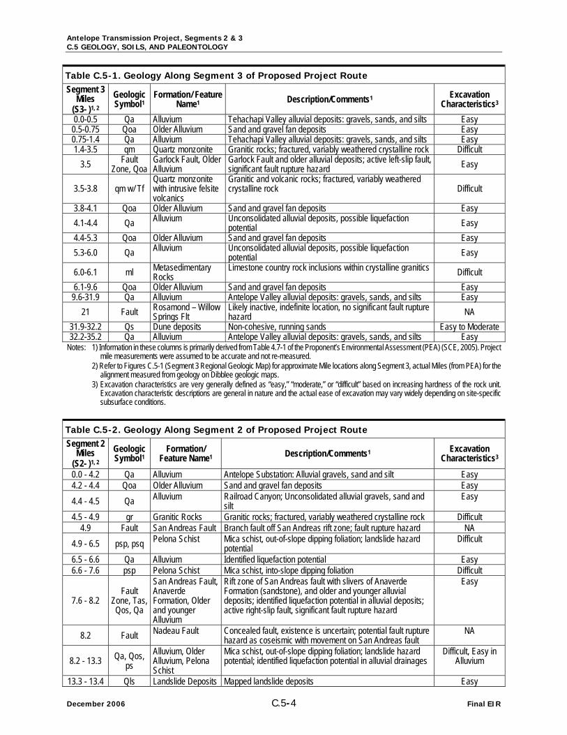
Project Geologic Conditions. Geologic conditions likely to be encountered during construction of the proposed Antelope Transmission Project, Segments 3 & 2 are summarized in Tables C.5-1 and C.5-2, respectively. The tables includes: name of the geologic formation or feature; the geologic symbol for the formation; the feature or formations name; a description and comments about the geologic features and the formation’s general rock type, lithology, and susceptibility to specific geologic hazards as appropriate; and general excavation characteristics of the unit related to excavation or drilling of tower and structure foundations. Descriptions of geologic units in the Project area are based on published geologic maps by Thomas Dibblee (1963, 1996, 1997, and 2001), and Thomas Dibblee and Gladys Louke (1970).
Antelope Transmission Project, Segments 2 & 3 C.5 GEOLOGY, SOILS, AND PALEONTOLOGY
December 2006 C.5-4 Final EIR
Table C.5-1. Geology Along Segment 3 of Proposed Project Route Segment 3
Miles (S3- )1, 2
Geologic Symbol1
Formation/ Feature Name1 Description/Comments1 Excavation
Characteristics3 0.0-0.5 Qa Alluvium Tehachapi Valley alluvial deposits: gravels, sands, and silts Easy
0.5-0.75 Qoa Older Alluvium Sand and gravel fan deposits Easy 0.75-1.4 Qa Alluvium Tehachapi Valley alluvial deposits: gravels, sands, and silts Easy 1.4-3.5 qm Quartz monzonite Granitic rocks; fractured, variably weathered crystalline rock Difficult
3.5 Fault Zone, Qoa
Garlock Fault, Older Alluvium
Garlock Fault and older alluvial deposits; active left-slip fault, significant fault rupture hazard Easy
3.5-3.8 qm w/ Tf Quartz monzonite with intrusive felsite volcanics
Granitic and volcanic rocks; fractured, variably weathered crystalline rock Difficult
3.8-4.1 Qoa Older Alluvium Sand and gravel fan deposits Easy 4.1-4.4 Qa Alluvium Unconsolidated alluvial deposits, possible liquefaction
potential Easy 4.4-5.3 Qoa Older Alluvium Sand and gravel fan deposits Easy 5.3-6.0 Qa Alluvium Unconsolidated alluvial deposits, possible liquefaction
potential Easy
6.0-6.1 ml Metasedimentary Rocks
Limestone country rock inclusions within crystalline granitics Difficult 6.1-9.6 Qoa Older Alluvium Sand and gravel fan deposits Easy
9.6-31.9 Qa Alluvium Antelope Valley alluvial deposits: gravels, sands, and silts Easy 21 Fault Rosamond – Willow
Springs Flt Likely inactive, indefinite location, no significant fault rupture hazard NA
31.9-32.2 Qs Dune deposits Non-cohesive, running sands Easy to Moderate 32.2-35.2 Qa Alluvium Antelope Valley alluvial deposits: gravels, sands, and silts Easy
Notes: 1) Information in these columns is primarily derived from Table 4.7-1 of the Proponent’s Environmental Assessment (PEA) (SCE, 2005). Project mile measurements were assumed to be accurate and not re-measured.
2) Refer to Figures C.5-1 (Segment 3 Regional Geologic Map) for approximate Mile locations along Segment 3, actual Miles (from PEA) for the alignment measured from geology on Dibblee geologic maps.
3) Excavation characteristics are very generally defined as “easy,” “moderate,” or “difficult” based on increasing hardness of the rock unit. Excavation characteristic descriptions are general in nature and the actual ease of excavation may vary widely depending on site-specific subsurface conditions.
Table C.5-2. Geology Along Segment 2 of Proposed Project Route Segment 2
Miles (S2- )1, 2
Geologic Symbol1
Formation/ Feature Name1 Description/Comments1 Excavation
Characteristics3 0.0 - 4.2 Qa Alluvium Antelope Substation: Alluvial gravels, sand and silt Easy 4.2 - 4.4 Qoa Older Alluvium Sand and gravel fan deposits Easy 4.4 - 4.5 Qa Alluvium Railroad Canyon; Unconsolidated alluvial gravels, sand and
silt Easy
4.5 - 4.9 gr Granitic Rocks Granitic rocks; fractured, variably weathered crystalline rock Difficult 4.9 Fault San Andreas Fault Branch fault off San Andreas rift zone; fault rupture hazard NA
4.9 - 6.5 psp, psq Pelona Schist Mica schist, out-of-slope dipping foliation; landslide hazard potential
Difficult
6.5 - 6.6 Qa Alluvium Identified liquefaction potential Easy 6.6 - 7.6 psp Pelona Schist Mica schist, into-slope dipping foliation Difficult
7.6 - 8.2 Fault
Zone, Tas, Qos, Qa
San Andreas Fault, Anaverde Formation, Older and younger Alluvium
Rift zone of San Andreas fault with slivers of Anaverde Formation (sandstone), and older and younger alluvial deposits; identified liquefaction potential in alluvial deposits; active right-slip fault, significant fault rupture hazard
Easy
8.2 Fault Nadeau Fault Concealed fault, existence is uncertain; potential fault rupture hazard as coseismic with movement on San Andreas fault
NA
8.2 - 13.3 Qa, Qos, ps
Alluvium, Older Alluvium, Pelona Schist
Mica schist, out-of-slope dipping foliation; landslide hazard potential; identified liquefaction potential in alluvial drainages
Difficult, Easy in Alluvium
13.3 - 13.4 Qls Landslide Deposits Mapped landslide deposits Easy

Antelope Transmission Project, Segments 2 & 3 C.5 GEOLOGY, SOILS, AND PALEONTOLOGY
Final EIR C.5-5 December 2006
Table C.5-2. Geology Along Segment 2 of Proposed Project Route Segment 2
Miles (S2- )1, 2
Geologic Symbol1
Formation/ Feature Name1 Description/Comments1 Excavation
Characteristics3
13.4 - 16.2 Qa, Qos, ps
Alluvium, Older Alluvium, Pelona Schist
Mica schist, out-of-slope dipping foliation; landslide hazard potential; identified liquefaction potential in alluvial drainages Difficult, Easy in
Alluvium
16.2 - 16.3 my Mylonitic Rocks Mylonite - a fine-grained, compact fine-grained laminated metamorphic rock Difficult
16.3 - 16.4 gr Granitic Rocks Granitic rocks; fractured, variably weathered crystalline rock Difficult 16.4 - 16.5 gnb Gneiss Banded gneiss Difficult 16.5 - 17.1 gr, Qa Granitic Rocks,
Alluvium Granitic rocks, variable weathering profile, possible landslide hazard; identified liquefaction potential in alluvial drainages
Difficult, Easy in Alluvium
17.1 - 17.3 di Dioritic Rocks Mafic granitic rocks; fractured, variably weathered crystalline rock Difficult
17.3 - 18.3 sy Syenite Granitic rocks, variable weathering profile, possible landslide hazard Difficult
17.4 Fault Unnamed fault Likely inactive, indefinite location, no significant fault rupture hazard NA
18.3 - 19.2 Qoa Older Alluvium Sand and gravel fan deposits Easy 19.2 - 19.3 di Dioritic Rocks Mafic granitic rocks; fractured, variably weathered crystalline
rock Difficult 19.3 - 19.4 Qoa Older Alluvium Sand and gravel fan deposits Easy 19.4 - 19.5 lgbd Lowe Granodiorite Granitic rocks; fractured, variably weathered crystalline rock Difficult 19.5 - 20.0 Qoa Older Alluvium Sand and gravel fan deposits Easy 20.0 - 20.9 Qa Alluvium Soledad Pass: Alluvial sand and clay Easy 20.9 - 21.0 Qoa Older Alluvium Sand and gravel fan deposits Easy 21.0 - 21.2 Qa Alluvium Identified liquefaction potential Easy 21.2 – 21.6 Qoa Older Alluvium Vincent Substation: Sand and gravel fan deposits Easy
Segment 2, Option A – portion that deviates from Segment 2 5.7 – 6.4 psp, psq Pelona Schist Mica schist, out-of-slope dipping foliation; landslide hazard
potential Difficult 6.4 – 6.5 Qa Alluvium Identified liquefaction potential Easy 6.5 –7.8 psp Pelona Schist Mica schist, into-slope dipping foliation Difficult
Segment 2, Option B– portion that deviates from Segment 2
8.1 – 8.2 Tas, Qos, Qa
Anaverde Formation, Older and younger Alluvium
Anaverde Formation (sandstone), and older and younger alluvial deposits; identified liquefaction potential in alluvial deposits; active right-slip fault, significant fault rupture hazard
Easy
8.2 Fault Nadeau Fault Concealed fault, existence is uncertain; potential fault
rupture hazard as coseismic with movement on San Andreas fault
NA
8.2 – 9.8 Qa, Qos, ps
Alluvium, Older Alluvium, Pelona Schist
Mica schist, out-of-slope dipping foliation; landslide hazard potential; identified liquefaction potential in alluvial drainages
Difficult, Easy in Alluvium
9.8 – 10.5 Qa Alluvium Anaverde Valley - Identified liquefaction potential Easy
10.5 – 11.2 ps Pelona Schist Mica schist, out-of-slope dipping foliation; landslide hazard potential Difficult
Notes: 1) Information in these columns is primarily derived from Table 4.7-1 of the PEA (SCE, 2005). Project mile measurements were assumed to be accurate and not remeasured.
2) Refer to Figures C.5-2 (Segment 2 Regional Geologic Map) for approximate Mile locations along Segment 2, actual Miles (from PEA) for the alignment measured from geology on Dibblee geologic maps.
3) Excavation characteristics are very generally defined as “easy,” “moderate,” or “difficult” based on increasing hardness of the rock unit. Excavation characteristic descriptions are general in nature and the actual ease of excavation may vary widely depending on site-specific subsurface conditions.

Antelope Transmission Project, Segments 2 & 3 C.5 GEOLOGY, SOILS, AND PALEONTOLOGY
December 2006 C.5-6 Final EIR
Previous Geotechnical Studies
Geotechnical investigations, including associated reports and memos, which were previously prepared for the existing Midway–Vincent No. 3 500-kV Transmission Line, were reviewed for the purpose of assessing the existing geotechnical conditions in the proposed Project area. The proposed Project would run generally parallel and/or adjacent to the existing Midway-Vincent No. 3 transmission line from Mile S3-33.4, through Antelope Substation, to Vincent Substation, including the majority of Segment 2 (with the exception of the Ritter Ranch re-route). As such, findings of geotechnical investigations conducted for the Midway-Vincent No. 3 transmission line are directly relevant to the portions of the proposed Project which parallel this line. Geotechnical investigations prepared for the existing Antelope and Vincent Substations were also reviewed for the purpose of assessing existing geotechnical conditions in the proposed Project area. These studies (Midway-Vincent No. 3 500-kV Transmission Line, Antelope Substation, and Vincent Substation) are discussed in detail below, as they relate to the proposed Project.
Midway – Vincent No. 3 500-kV Transmission Line
• Design Report: No. 3 Midway – Vincent 500kV Transmission Line, Tower Foundation Design Data, Report No. 232; Engineering Department, Southern California Edison, Rosemead, California, November 18, 1971.
This report summarizes the findings of a soil condition investigation conducted for the construction of the No. 3 Midway – Vincent 500-kV Transmission Line and includes soil boring data for approximately 46 soil borings along its alignment at sporadic locations adjacent to planned tower locations. Approximately 15 of these borings, depths ranging from 20 to 35 feet, are along the portion of the alignment that is parallel to a portion of Segment 2, between the southwestern edge of the San Andreas Rift Zone and Antelope Substation. Soil materials in these borings correlate with the mapped geology. Near surface and subsurface materials encountered in the borings located in the Antelope Valley consisted primarily of alluvium of loose to dense silty sands with varying amounts of gravel and silt. Borings across Portal and Ritter Ridges revealed igneous (granitic) and metamorphic (Pelona Schist) rocks which were weathered at the surface and moderately hard at depth, with a thin layer of alluvium/colluvium on the surface in some areas. On the west side of the Leona Valley, within and along the base of the Sierra Pelona, Pelona Schist in varying stages of weathering and schist derived colluvium were encountered in the borings. Groundwater was not noted in any of the borings along this segment except for one boring within the Anaverde Creek drainage, which had perched groundwater at about 16 feet below ground surface (bgs).
Antelope Substation
• Letter Report: Antelope Substation – Pile Design Data; T.M. Leps, Chief Civil Engineer, April 25, 1952
• Memorandum: Antelope Substation, Foundation Investigation; E.E. Chandler, Assistant Civil Engineer, July 19, 1957
• Antelope Substation Boring Logs and Soil Test Results; December 1996
• Letter Report: Foundation Design Recommendations, Antelope Substation Additions, Los Angeles County, California; Engineering and Technical Services Geotechnical Group, January 9, 1997
The reports and data reviewed for the Antelope Substation indicate that the materials underlying the site consist of Recent Alluvium, composed primarily of loose to medium dense silty sand with gravel, with local gravelly, cobbly, and clayey layers. No groundwater was encountered in any of the borings conducted for these investigations; the borings were conducted to a maximum depth of 40 feet.

Antelope Transmission Project, Segments 2 & 3 C.5 GEOLOGY, SOILS, AND PALEONTOLOGY
Final EIR C.5-7 December 2006
Vincent Substation
• Geotechnical Report: Report of Foundation Investigation, Proposed Vincent Substation, Angles Forest Highway, Vincent, California, August 28, 1963; by LeRoy Crandall & Associates.
This report indicates that materials underlying the Vincent Substation site consist of alluvial deposits, composed of medium dense to dense interbedded silty sand and sand, with local lenses of gravelly and clayey sand and sandy silt. Groundwater was not encountered in any of the borings to a total depth of 35 feet below ground surface.
Slope Stability
Important factors that affect the slope stability of an area include the steepness of the slop, the relative strength of the underlying rock material, and the thickness and cohesion of the overlying colluvium. The steeper the slope and/or the less strong the rock, the more likely the area is susceptible to landslides. The steeper the slope and the thicker the colluvium, the more likely the area is susceptible to debris flows. Such areas can be identified on maps showing the steepness of slopes (Graham and Pike, 1998) when used in combination with a geologic map. Another indication of unstable slopes is the presence of old or recent landslides or debris flows.
Most of the proposed route crosses flat land and does not cross any areas identified as an existing landslide. Segment 3 does cross hilly terrain of the Tehachapi Mountains, however it does not cross any mapped landslides and the granitic terrain underlying this area is not typically prone to landslides in this area. Segment 2 crosses numerous mapped small to moderate sized landslides (CGS, 2003c) between Miles S2- 8.0 and S2-14.0, all mapped in the landslide prone Pelona Schist. Option A does not cross any mapped landslides, however two mapped landslide are located upslope of the alignment near where it rejoins the proposed Segment 2 route. Option B crosses one landslide where it diverges from the proposed Segment 2 alignment (CGS, 2003c). Other landslides, although not crossed by the Segment 2 alignment, have also been mapped in the Project vicinity as it crosses the Sierra Pelona, primarily in the Pelona Schist. Unmapped landslides and areas of localized slope instability may be encountered along Segments 3 and 2 in the hills traversed by the proposed Project alignment.
Soils
The soils along the proposed transmission line route reflect the underlying rock type, the extent of weathering of the rock, the degree of slope, and the degree of modification by man. Soil mapping by the USDA National Resource Conservation Service (NRCS) has provided information for surface and near-surface subsurface soil materials. The Project alignment traverses portions of two NRCS soil survey reports, the Soil Survey of Antelope Valley, California (1970) and the Soil Survey of Kern County, Southeastern Part, California (1981). A summary of the significant characteristics of the major soil units traversed by the Project is presented in Tables C.5-3 and C.5-4; soil units are listed in order of first occurrence along the segment and may occur in multiple locations.
Table C.5-3. Major Soils along the Segment 3 Transmission Line Route
Risk of Corrosion Soil Name Description
Hazard of Erosion on Roads and
Trails1 Uncoated Steel Concrete Havala Sandy loam on 2 to 9% slopes Slight to Moderate High Low Tujunga Loamy sand on 2 to 5% slopes Slight Low Low Walong Sandy loam on 15 to 30% and 30 to 50% slopes Severe Moderate Low Tunis Sandy loam on 5 to 30% slopes Severe Moderate Low Pajuela-Whitewolf Gravelly sandy loam on 30 to 50% slopes and
loamy sand on 0 to 5% slopes Moderate to
Severe Moderate to
High Low

Antelope Transmission Project, Segments 2 & 3 C.5 GEOLOGY, SOILS, AND PALEONTOLOGY
December 2006 C.5-8 Final EIR
Table C.5-3. Major Soils along the Segment 3 Transmission Line Route
Risk of Corrosion Soil Name Description
Hazard of Erosion on Roads and
Trails1 Uncoated Steel Concrete
Cajon Loamy sand on 0 to 9% slopes and gravelly loamy sand on 2 to 9% slopes Slight to Moderate Moderate Low
Garlock Loamy sand on 2 to 9% slopes Moderate High Low Adelanto Loamy sand on 2 to 5% slopes and coarse sandy
loam on 2 to 9% slopes Slight to Moderate High Low Sunrise Sandy loam, shallow sandy loam, and loam Slight High Low Rosamond Fine sandy loam, loam, and silty clay loam Slight High Low Greenfeild Sandy loam on 2 to 9% slopes, eroded in areas Slight to Moderate Low Low
Note: Sources for soil mapping along this alignment are the Soil Survey of Antelope Valley and the Soil Survey of Kern County, Southeastern Part 1) Erosion Hazard: Slight – little or no erosion is likely, Moderate – some erosion is likely and that simple erosion control measures are needed, Severe – significant erosion is expected and major erosion control measures may be needed.
Table C.5-4. Major Soils along the Segment 2 Transmission Line Route
Risk of Corrosion Soil Name Description
Hazard of Erosion on Roads and
Trails1 Uncoated Steel Concrete Greenfield Sandy loam on 2 to 9% slopes, eroded in areas Slight to Moderate Low Low Hanford Coarse sandy loam on 2 to 15% slopes, also
found along Option B Moderate to
Severe Low Low
Vista Coarse Sandy loam on 30 to 50% slopes, eroded in places, also found along Option A Severe Low Low
Amargosa Rocky coarse sandy loam on 9 to 55% slopes, eroded in places, also found along Option A Severe Moderate Low
Godde Loam on 15 to 305 slopes and rocky loam on 30 to 50% slopes, also found along Options A and B Severe Moderate Moderate
Anaverde Loam on 15 to 305 slopes and rocky loam on 30 to 50% slopes, also found along Option B Severe Moderate Moderate
Los Posas-Toomes Rocky loams on 30 to 50% slopes Severe High Low Wyman Gravelly loam on 2 to 15% slopes Moderate Low Low
Note: Sources for soil mapping along this alignment are the Soil Survey of Antelope Valley 1) Erosion Hazard: Slight – little or no erosion is likely, Moderate – some erosion is likely and that simple erosion control measures are needed, Severe – significant erosion is expected and major erosion control measures may be needed.
Corrosivity of soils is generally related to several key parameters: soil resistivity, presence of chlorides and sulfates, oxygen content, and pH. Typically, the most corrosive soils are those with the lowest pH and highest concentration of chlorides and sulfates. High sulfate soils are corrosive to concrete and may prevent complete curing reducing its strength considerably. Low pH and/or low resistivity soils could corrode buried or partially buried metal structures.
The properties of soil which influence erosion by rainfall and runoff are ones which affect the infiltration capacity of a soil and those which affect the resistance of a soil to detachment and being carried away by falling or flowing water. Soils containing high percentages of fine sands and silt and that may have low in density are generally the most erodible. These soil types generally coincide with soils such as young alluvium and other surficial deposits, which likely occur in areas throughout the Project area. As the clay and organic matter content of these soils increases, the potential for erosion decreases. Clays act as a binder to soil particles, thus reducing the potential for erosion. However, while clays have a tendency to resist erosion, once eroded they are easily transported by water. Clean, well-drained, and well-graded gravels and gravel-sand mixtures are usually the least erodible soils. Soils with high infiltration rates and permeabilities reduce the amount of runoff.

Antelope Transmission Project, Segments 2 & 3 C.5 GEOLOGY, SOILS, AND PALEONTOLOGY
Final EIR C.5-9 December 2006
Expansive soils are characterized by their ability to undergo significant volume change (shrink and swell) due to variation in soil moisture content. Changes in soil moisture could result from rainfall, landscape irrigation, utility leakage, roof drainage, and/or perched groundwater. Expansive soils are typically very fine grained with a high to very high percentage of clay.
Mineral Resources
No significant sand and gravel resources have been identified by the State and there are no current production areas in the Project area (CDOC, 1987); however, potential sand and gravel resources may be present in the Project area. No significant production areas are located in or near the project area and none are anticipated in the future (Kohler, 2002). A review of the California Department of Conservation Oil, Gas, and Geothermal Resources (DOGGR) website, http://www.consrv.ca.gov/DOG/, indicates that there are no oil, gas, or geothermal resources identified in the Project area.
No significant mineral resources have been identified in the vicinity of Segment 2. There are, however, several mineral resources identified in the vicinity of Segment 3. Gold and uranium resources have been mined from the Rosamond Hills east of and adjacent to the Segment 3 route. Gold is still listed as a principal mineral resource in this area; uranium is not (CGS, 2000). Limestone and dolomite are being mined along the flanks of the Tehachapi Mountains southeast of the alignments. Active limestone quarries are located approximately 2,000 feet south of Segment 3 approximately between Miles S3-5.3 and S3-5.7, near to the Cal Cement facility, which is located approximately 1.5 miles west of Substation One.
C.5.1.3 Seismic Hazards
Faults and Seismicity
The seismicity of southern California is dominated by the intersection of the north-northwest trending San Andreas Fault system and the east-west trending Transverse Ranges fault system. Both systems are responding to strain produced by the relative motions of the Pacific and North American Tectonic Plates. This strain is relieved by right-lateral strike-slip faulting on the San Andreas and related faults, left-lateral strike slip on the Garlock fault, and by vertical, reverse-slip or left-lateral strike-slip displacement on faults in the Transverse Ranges. The effects of this deformation include mountain building; basin development; deformation of Quaternary marine terraces; widespread regional uplift; and generation of earthquakes. Both the Transverse Ranges and northern Los Angeles County area are characterized by numerous geologically young faults. These faults can be classified as historically active, active, potentially active, or inactive, based on the following criteria (CGS, 1999):
• Faults that have generated earthquakes accompanied by surface rupture during historic time (approximately the last 200 years) and faults that exhibit aseismic fault creep1 are defined as Historically Active.
• Faults that show geologic evidence of movement within Holocene time (approximately the last 11,000 years) are defined as Active.
• Faults that show geologic evidence of movement during the Quaternary (approximately the last 1.6 million years) are defined as Potentially Active.
• Faults that show direct geologic evidence of inactivity during all of Quaternary time or longer are classified as Inactive.
Although it is difficult to quantify the probability that an earthquake will occur on a specific fault, this classification is based on the assumption that if a fault has moved during the Holocene epoch, it is likely to produce earthquakes in the future. Blind thrust faults do not intersect the ground surface, and thus they are not 1 Movement along a fault that does not entail earthquake activity.
Antelope Transmission Project, Segments 2 & 3 C.5 GEOLOGY, SOILS, AND PALEONTOLOGY
December 2006 C.5-10 Final EIR
classified as active or potentially active in the same manner as faults that are present at the earth’s surface. Blind thrust faults are seismogenic structures and thus the activity classification of these faults is predominantly based on historic earthquakes and microseismic activity along the fault.
Since periodic earthquakes accompanied by surface displacement can be expected to continue in the study area through the lifetime of the proposed Project, the effects of strong groundshaking and fault rupture are of primary concern to safe operation of the proposed transmission line and associated facilities.
The Project area will be subject to ground shaking associated with earthquakes on faults of the San Andreas, Garlock, and Transverse Ranges fault systems. Active faults of the San Andreas system are predominantly strike-slip faults accommodating translational2 movement. The predominant active faults in the Project area are the San Andreas and Garlock faults.
Active reverse or thrust faults3 in the Transverse Ranges include blind thrust faults4 responsible for the 1987 Whittier Narrows Earthquake and 1994 Northridge Earthquake, and the range-front faults5 responsible for uplift of the Santa Susana and San Gabriel Mountains. The Transverse Ranges fault system consists primarily of blind, reverse, and thrust faults accommodating tectonic compressional stresses in the region. Blind faults have no surface expression and have been located using subsurface geologic and geophysical methods. This combination of translational and compressional stresses gives rise to diffuse seismicity across the region.
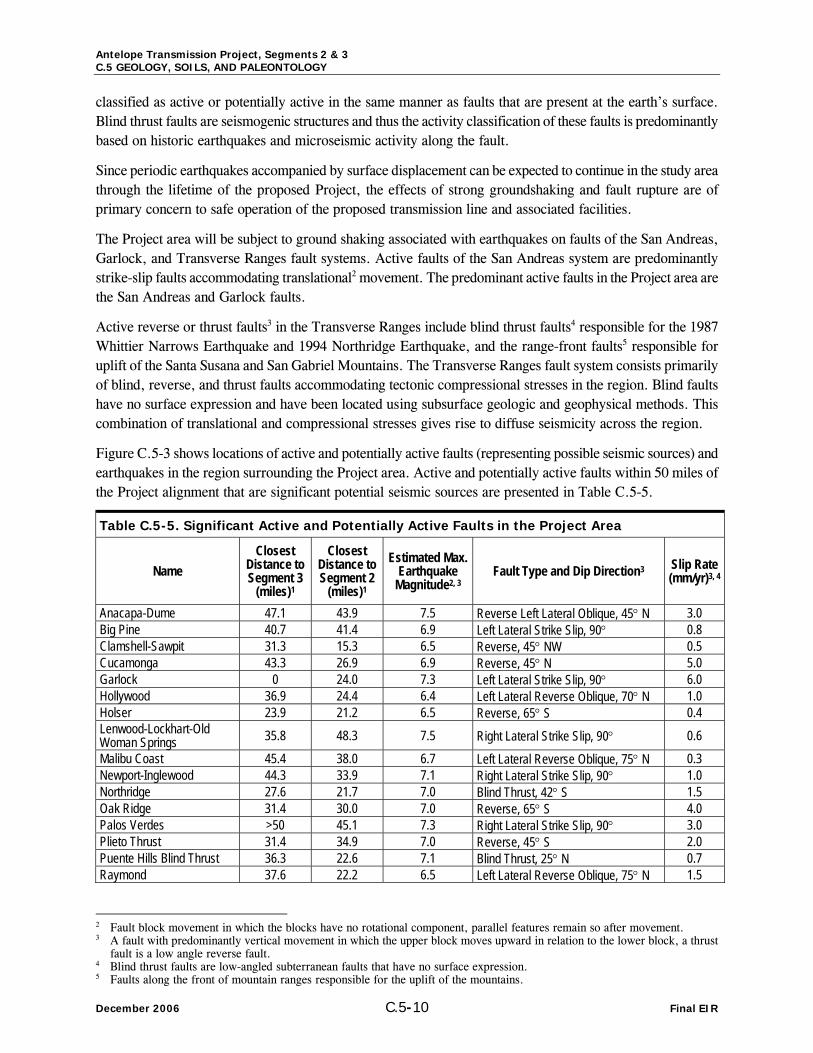
Figure C.5-3 shows locations of active and potentially active faults (representing possible seismic sources) and earthquakes in the region surrounding the Project area. Active and potentially active faults within 50 miles of the Project alignment that are significant potential seismic sources are presented in Table C.5-5.
Table C.5-5. Significant Active and Potentially Active Faults in the Project Area
Name Closest
Distance to Segment 3
(miles)1
Closest Distance to Segment 2
(miles)1
Estimated Max. Earthquake
Magnitude2, 3 Fault Type and Dip Direction3 Slip Rate
(mm/yr)3, 4
Anacapa-Dume 47.1 43.9 7.5 Reverse Left Lateral Oblique, 45° N 3.0 Big Pine 40.7 41.4 6.9 Left Lateral Strike Slip, 90° 0.8 Clamshell-Sawpit 31.3 15.3 6.5 Reverse, 45° NW 0.5 Cucamonga 43.3 26.9 6.9 Reverse, 45° N 5.0 Garlock 0 24.0 7.3 Left Lateral Strike Slip, 90° 6.0 Hollywood 36.9 24.4 6.4 Left Lateral Reverse Oblique, 70° N 1.0 Holser 23.9 21.2 6.5 Reverse, 65° S 0.4 Lenwood-Lockhart-Old Woman Springs 35.8 48.3 7.5 Right Lateral Strike Slip, 90° 0.6 Malibu Coast 45.4 38.0 6.7 Left Lateral Reverse Oblique, 75° N 0.3 Newport-Inglewood 44.3 33.9 7.1 Right Lateral Strike Slip, 90° 1.0 Northridge 27.6 21.7 7.0 Blind Thrust, 42° S 1.5 Oak Ridge 31.4 30.0 7.0 Reverse, 65° S 4.0 Palos Verdes >50 45.1 7.3 Right Lateral Strike Slip, 90° 3.0 Plieto Thrust 31.4 34.9 7.0 Reverse, 45° S 2.0 Puente Hills Blind Thrust 36.3 22.6 7.1 Blind Thrust, 25° N 0.7 Raymond 37.6 22.2 6.5 Left Lateral Reverse Oblique, 75° N 1.5
2 Fault block movement in which the blocks have no rotational component, parallel features remain so after movement. 3 A fault with predominantly vertical movement in which the upper block moves upward in relation to the lower block, a thrust
fault is a low angle reverse fault. 4 Blind thrust faults are low-angled subterranean faults that have no surface expression. 5 Faults along the front of mountain ranges responsible for the uplift of the mountains.

Antelope Transmission Project, Segments 2 & 3 C.5 GEOLOGY, SOILS, AND PALEONTOLOGY
Final EIR C.5-11 December 2006
Table C.5-5. Significant Active and Potentially Active Faults in the Project Area
Name Closest
Distance to Segment 3
(miles)1
Closest Distance to Segment 2
(miles)1
Estimated Max. Earthquake
Magnitude2, 3 Fault Type and Dip Direction3 Slip Rate
(mm/yr)3, 4
San Andreas – Carrizo Segment 12.1 12.1 7.4 Right Lateral Strike Slip, 90° 34.0 San Andreas – Mojave Segment 4.2 0 7.4 Right Lateral Strike Slip, 90° 30.0 San Cayetano 31.2 31.1 7.0 Reverse, 60° N 6.0 San Gabriel 22.1 14.5 7.2 Right Lateral Strike Slip, 90° 1.0 San Jose 48.7 32.0 6.4 Left Lateral Reverse Oblique, 75° NW 0.5 Santa Monica 42.6 33.2 6.6 Left Lateral Reverse Oblique, 75° N 1.0 Santa Susana 23.1 19.7 6.7 Reverse, 55° N 5.0 Santa Ynez 35.0 35.0 7.1 Left Lateral Strike Slip, 90° 2.0 Sierra Madre 23.7 12.2 7.2 Reverse, 45° N 2.0 San Fernando 19.6 13.9 6.7 Reverse, 45° N 2.0 Simi-Santa Rosa 32.7 30.6 7.0 Left Lateral Reverse Oblique, 60° N 1.0 Upper Elysian Park Thrust 36.4 23.9 6.4 Blind Thrust, 50° NE 1.3 Verdugo 23.9 15.9 6.9 Reverse, 45° NE 0.5 White Wolf 15.2 38.8 7.3 Reverse Left Lateral Oblique, 60° S 2.0 Whittier 49.6 33.8 6.8 Right Lateral Strike Slip, 90° 2.5
Notes: 1) Fault distances obtained using the EQFault computer program (Blake, 2000), based on digitized data adapted and modified from the 2002 CGS fault database.
2) Maximum Earthquake Magnitude – the maximum earthquake that appears capable of occurring under the presently known tectonic framework, using the Richter scale.
3) Fault parameters from the CGS Revised 2002 California Probabilistic Seismic Hazard Maps report, Appendix A - 2002 California Fault Parameters.
4) References to fault slip rates are traditionally presented in millimeters per year.
Strong Groundshaking
An earthquake is classified by the amount of energy released, which traditionally has been quantified using the Richter scale. Recently, seismologists have begun using a Moment Magnitude (M) scale because it provides a more accurate measurement of the size of major and great earthquakes. For earthquakes of less than M 7.0, the Moment and Richter Magnitude scales are nearly identical. For earthquake magnitudes greater than M 7.0, readings on the Moment Magnitude scale are slightly greater than a corresponding Richter Magnitude.
The intensity of the seismic shaking, or strong ground motion, during an earthquake is dependent on the distance between the Project area and the epicenter of the earthquake, the magnitude of the earthquake, and the geologic conditions underlying and surrounding the Project area. Earthquakes occurring on faults closest to the Project area would most likely generate the largest ground motion.
The intensity of earthquake induced ground motions can be described using peak site accelerations, represented as a fraction of the acceleration of gravity (g). GIS data based on the CGS Probabilistic Seismic Hazard Assessment (PSHA) Maps was used to estimate peak ground accelerations along the Project alignment. PSHA Maps depict peak ground accelerations with a 10 percent probability of exceedance in 50 years. The results for the proposed Project are presented in Table C.5-64.

Antelope Transmission Project, Segments 2 & 3 C.5 GEOLOGY, SOILS, AND PALEONTOLOGY
December 2006 C.5-12 Final EIR
Table C.5-6. Peak Ground Accelerations Approximate Proposed Transmission
Line Mile1 Total Length of Segments
(miles) Peak Ground Acceleration
Segment 3 S3-15.7 to S3-26.8 11.1 0.3 – 0.4g
S3-9.3 to S3-15.7 and S3-26.8 to S3-31.1 10.7 0.4 – 0.5g
S3-0 to S3-9.3 and S3-31.1 to S3-35.2 13.4 0.5 – 0.6g Segment 2
S2-0.0 to S2-2.0 2.0 0.5 – 0.6g S2-2.0 to S2-6.6, S2-11.8 to S2-13.2, and
S2-17.6 to S2-21.6 Option A: 5.7-7.1
9.9 1.4
0.6 – 0.7g
S2-6.6 to S2-11.8 and S2-13.2 to S2-17.6 Option A: 7.1 to 7.8
Option B: 8.1 to 11.2
9.6 0.7 3.1
0.7 – 0.8g
A review of historic earthquake activity from 1800 to 1999 indicates that eight earthquakes of magnitude M 6.0 or greater have occurred within 50 miles (80 kilometers) of the proposed Project alignment (CGS, 2006). The M 5.9 Whittier Narrows earthquake of 1987 is also included in the table because it was a significantly damaging earthquake within 50 miles of the Project alignment. Also included in the table is the 1857 Fort Tejon Earthquake. The location of this earthquake is uncertain due to lack of seismic instrumentation at the time and due to the widespread damage and long rupture length; however, this very large earthquake produced surface rupture on the local strands of the San Andreas Fault. A summary of each of these eight earthquake events is presented in Table C.5-7.
Table C.5-7. Significant Historic Earthquakes
Date Approximate
Distance (miles)
Earthquake Magnitude1
Name, Location, or Region Affected Comments2
December 8, 1812 43.1 7.5? Wrightwood
Earthquake Caused collapse of Mission at San Juan Capistrano resulting in the death of 40 people.
July 11, 1855 18.7 6.0 Los Angles Region
The bells at San Gabriel Mission Church were thrown down and twenty-six buildings in Los Angeles were damaged.
January 9, 1857
Unknown, currently
assumed in the San Luis Obispo area.
Estimated from 7.9 to
8.25 Fort Tejon Earthquake
One of the largest earthquakes ever reported in the US. This earthquake caused damage from Monterey to San Bernardino and caused a surface rupture of greater than 220 miles in length. Due to sparse population of the time in it only resulted in 2 deaths. Average displacement along the fault was 15 feet, with a maximum displacement of 30 feet in the Carrizo Plain area.
January 16, 1857 34.0 6.3 Generally felt in the
Los Angeles Region Aftershock of the January 9, 1857 M7.9 Fort Tejon Earthquake.
July 29, 1894 48.1 6.2 Lytle Creek region Felt from Bakersfield to San Diego. Minor damage in the
Mojave and Los Angeles areas. July 21,1952 45.3 7.3 Kern County
Earthquake Resulted in the death of 12 people and $60 million in property Damage.
February 9, 1971 6.6 6.6 San Fernando
(Sylmar) Earthquake
This earthquake caused over $500 million in damage and resulted in 65 deaths. As A result of the damage from this earthquake, building codes were strengthened and the Alquist Priolo Special Studies Zone Act of 1972 was passed.

Antelope Transmission Project, Segments 2 & 3 C.5 GEOLOGY, SOILS, AND PALEONTOLOGY
Final EIR C.5-13 December 2006
Table C.5-7. Significant Historic Earthquakes
Date Approximate
Distance (miles)
Earthquake Magnitude1
Name, Location, or Region Affected Comments2
October 1, 1987 36.3 5.9 Whittier Narrows
Earthquake Resulted in eight deaths and $358 million in property damage. This earthquake occurred on a previously unknown blind thrust fault, the Puente Hills Fault.
January 17, 1994 16.0 6.7 Northridge
Earthquake
Resulted in 60 deaths and approximately $15 billion in property damage. Damage was significant and widespread, including collapsed freeway overpasses and more than 40,000 damaged buildings in Los Angeles, Ventura, Orange, and San Bernardino Counties.
Notes: 1) Earthquake magnitudes and locations before 1932 are estimated by Toppozada and others (1978, 1981, and 1982) based on reports of damage and felt effects.
2) Earthquake damage information compiled from the Southern California Data Center (SCEDC, 2006a and 2006b) and National Earthquake Information Center (NEIC, 2005) websites.
Seven aftershocks measuring greater than M6.0 of larger earthquakes have also occurred within 50 miles of the Project alignment, but are not included in the table. Figure C.5-3 shows locations of historic earthquakes in the Project area and surrounding region.
Fault Rupture
Perhaps the most important single factor to be considered in the seismic design of electric transmission lines and underground cables crossing active faults is the amount and type of potential ground surface displacement.
The Project alignment crosses two active faults: Segment 3 crosses the San Gabriel fault at approximately Mile S3-3.5 and Segment 2 (Options A and B) cross the San Andreas Fault Zone between approximately Mile S2-7.6 and Mile S2-8.2. Both the San Andreas and Garlock faults are mapped as Earthquake Fault Zones6 in the vicinity of the Project alignment crossings. Although the Project will not be subject to the regulations and guidelines related to the Alquist-Priolo Special Studies Zones Act because there will be no occupied structures constructed in the Earthquake Fault Zones as part of this Project, the presence of these mapped zones indicates significant potential for fault rupture in the areas the Project crosses the “zones”. The limits of these zones in the vicinity of the Project alignment fault crossings are presented on Figure C.5-4.
Fault rupture has occurred historically within the Project area. The 1857 Fort Tejon Earthquake caused rupture of the local strands of the San Andreas Fault. Although future earthquakes could occur anywhere along the length of the San Andreas and Garlock faults, only regional strike-slip earthquakes of magnitude 6.0 or greater are likely to be associated with surface fault rupture and offset (CGS, 1996). It is also important to note that earthquake activity from unmapped subsurface faults is a possibility that is currently not predictable.
Liquefaction
Liquefaction is the phenomenon in which saturated granular sediments temporarily lose their shear strength during periods of earthquake-induced strong groundshaking. The susceptibility of a site to liquefaction is a function of the depth, density, and water content of the granular sediments and the magnitude and frequency of earthquakes in the surrounding region. Saturated, unconsolidated silts, sands, and silty sands within 50 feet of the ground surface are most susceptible to liquefaction. Liquefaction related phenomena include lateral
6 The Alquist-Priolo Special Studies Zones Act, passed in 1972, requires the establishment of “Earthquake Fault Zones” (formerly
known as “special studies zones”) along known active faults in California. In order to be designated as an “Earthquake Fault Zone” a fault must be “sufficiently active and well defined” according to State guidelines. Development of occupied structures within these zones is regulated and must conform to strict building restrictions and codes, which are enforced to reduce the potential for damage and loss of life due to fault displacement.
Antelope Transmission Project, Segments 2 & 3 C.5 GEOLOGY, SOILS, AND PALEONTOLOGY
December 2006 C.5-14 Final EIR
spreading, ground oscillation, flow failures, loss of bearing strength, subsidence, and buoyancy effects (Youd, 1978). In addition, densification of the soil resulting in vertical settlement of the ground can also occur.
In order to determine liquefaction susceptibility of a region, three major factors must be analyzed. These include: (a) the density and textural characteristics of the alluvial sediments; (b) the intensity and duration of groundshaking; and (c) the depth to groundwater. Surface materials beneath the portions of Segment 2 and Options A and B meet the criteria for liquefaction in the young alluvial deposits in the Leona Valley, Anaverde Valley, and in Soledad Canyon, and in the alluvial and creek deposits of intervening drainages. Older and finer or coarser grained, indurated, and/or well-drained materials are less susceptible to liquefaction. Alluvial deposits underlying the portions of Segments 2 and 3 that cross the Antelope and Tehachapi Valley areas are not expected to be liquefiable due to deep groundwater levels in these areas.
Seismic hazard mapping, delineating areas of potential liquefaction and seismically induced landslides, has been conducted by the State of California for six of the 7.5-Minute Quadrangles that the Project alignment traverses: the Little Butte (no zones delineated), Del Sur, Lancaster West, Ritter Ridge, Palmdale, and Pacifico Mountain Quadrangles (CGS, 2003a, 2003b, 2003c, 2005a, 2005b, and 2005c). This mapping covers all of Segment 2, but only the southern half of Segment 3. Only Segment 2 traverses mapped liquefaction hazard zones, on the Ritter Ridge and Pacifico Mountain Quadrangles.
Seismic Slope Instability
Other forms of seismically induced ground failures which may affect the Project area include ground cracking and seismically induced landslides. Landslides triggered by earthquakes have been a significant cause of earthquake damage; in southern California large earthquakes such as the 1971 San Fernando and 1994 Northridge earthquakes triggered landslides that were responsible for destroying or damaging numerous structures, blocking major transportation corridors, and damaging life-line infrastructure. Areas that are most susceptible to earthquake-induced landslides are steep slopes in poorly cemented or highly fractured rocks, areas underlain by loose, weak soils, and areas on or adjacent to existing landslide deposits. Areas that are underlain by landslide prone units, such as the Pelona schist, with moderate to steep slopes, and previously existing landslides, both mapped and unmapped, are particularly susceptible to this type of ground failure. Segment 2 crosses areas mapped as areas of potential earthquake-induced landslides on the CGS seismic hazard maps for four of the mapped quadrangles along the alignment, the Del Sur, Ritter Ridge, Palmdale, and Pacifico Mountain (CGS, 2003a, 2003b, 2003c, and 2005a).
C.5.1.4 Paleontology
Determination of the “significance” of a fossil can only occur after a fossil has been found and identified by a qualified paleontologist. Until then, the actual significance is unknown. However, fossils are considered to be scientifically significant if they meet or potentially meet any one or more of the following criteria:
• Taxonomy – fossils that are scientifically judged to be important for representing rare or unknown taxa, such as defining a new species.
• Evolution – fossils that are scientifically judged to represent important stages or links in evolutionary relationships, or fill gaps or enhance under-represented intervals in the stratigraphic record.
• Biostratigraphy – fossils that are scientifically judged to be important for determining or constraining relative geologic (stratigraphic) age, or for use in regional to interregional stratigraphic correlation problems.
• Paleoecology – fossils that are scientifically judged to be important for reconstructing ancient organism community structure and interpretation of anc ient sedimentary environments.
Antelope Transmission Project, Segments 2 & 3 C.5 GEOLOGY, SOILS, AND PALEONTOLOGY
Final EIR C.5-15 December 2006
• Taphonomy – fossils that are scientifically judged to be exceptionally well or unusually or uniquely preserved, or are relatively rare in the stratigraphy.
The most useful designation for paleontological resources in an EIR document is the “sensitivity” of a particular geologic unit. Sensitivity refers to the likelihood of finding significant fossils within a geologic unit. The following levels of sensitivity recognize the important relationship between fossils and the geologic formations within which they are preserved.
• High Sensitivity. High sensitivity is assigned to geologic formations known to contain paleontological localities with rare, well-preserved, and/or critical fossil materials for stratigraphic or paleoenvironmental interpretation, and fossils providing important information about the paleobiology and evolutionary history (phylogeny) of animal and plant groups. Generally speaking, highly sensitive formations are known to produce vertebrate fossil remains or are considered to have the potential to produce such remains.
• Moderate Sensitivity. Moderate sensitivity is assigned to geologic formations known to contain paleontological localities with moderately preserved, common elsewhere, or stratigraphically long-ranging fossil material. The moderate sensitivity category is also applied to geologic formations that are judged to have a strong, but unproven potential for producing important fossil remains (e.g., Pre-Holocene sedimentary rock units representing low to moderate energy, of marine to non-marine depositional settings).
• Low Sensitivity. Low sensitivity is assigned to geologic formations that, based on their relative youthful age and/or high-energy depositional history, are judged unlikely to produce important fossil remains. Typically, low sensitivity formations may produce invertebrate fossil remains in low abundance.
• Marginal Sensitivity. Marginal sensitivity is assigned to geologic formations that are composed either of pyroclastic volcanic rocks or metasedimentary rocks, but which nevertheless have a limited probability for producing fossil remains from certain sedimentary lithologies at localized outcrops.
• Zero Sensitivity. Zero sensitivity is assigned to geologic formations that are entirely plutonic (volcanic rocks formed beneath the earth’s surface) in origin and therefore have no potential for producing fossil remains.
Significant California fossils are typically vertebrate fossils of late Quaternary and Tertiary age. The age of the geologic units, their terrestrial origin, and the discovery of vertebrates in late Quaternary and Tertiary-aged units in the region indicates that there is a likelihood that significant fossils may be found during excavation for new tower footings in locations along the Project route. Locations where metamorphic or crystalline rocks occur have no potential for paleontological resources (Zero sensitivity). A paleontologic survey for the Antelope Transmission Project was conducted for SCE by Dr. Grant Hurlburt, PhD, from the California State University at Stanislaus (Hurlbert, 2006). This report indicates that although no known fossil localities are present along the proposed Project route, significant fossils have been recovered from Older (Plio-Pleistocene) Alluvium in the general Project area, resulting in a high sensitivity for this unit. Fossils that have been encountered in the Older Alluvium include: horse, mammoth, gopher snake, kingsnake, leopard lizard, cottontail rabbit, pocket mouse, Kangaroo rat, and pocket gopher. Segment 2 crosses small outcrops of the Pliocene Anaverde Formation in the San Andreas Rift zone and the SCE study indicates that this unit could contain significant fossils and internet research reveals that the Anaverde Formation is known to contain plant fossils (UCMP website, 2006) resulting in a moderate to high sensitivity for this unit.
C.5.2 Regulatory Framework Geologic resources and geotechnical hazards are governed primarily by local jurisdictions. The conservation elements and seismic safety elements of city and county general plans contain policies for the protection of geologic features and avoidance of hazards, but do not specifically address transmission line construction projects.
CEQA is the major environmental statute that guides the design and construction of new transmission lines in California. This statute set forth a specific process of environmental impact analysis and public review. In
Antelope Transmission Project, Segments 2 & 3 C.5 GEOLOGY, SOILS, AND PALEONTOLOGY
December 2006 C.5-16 Final EIR
addition, the project owner must comply with additional state and local applicable statutes, regulations and policies. Relevant, and potentially relevant, statutes, regulations and policies are discussed below.
C.5.2.1 State
Geologic and Seismic Hazards
California Environmental Quality Act (CEQA) (Pub. Resource Code sections 21000-21177.1). CEQA was adopted in 1970 and applies to most public agency decisions to carry out, authorize or approve projects that may have adverse environmental impacts. CEQA requires that agencies inform themselves about the environmental effects of their proposed actions, consider all relevant information, provide the public an opportunity to comment on the environmental issues, and avoid or reduce potential environmental harm whenever feasible. Relevant CEQA sections include those for protection of geological and mineral resources, protection of soil from erosion.
The Alquist-Priolo Earthquake Fault Zoning Act of 1972 (formerly the Special Studies Zoning Act) regulates development and construction of buildings intended for human occupancy to avoid the hazard of surface fault rupture. While this Act does not specifically regulate overhead transmission lines, it does help define areas where fault rupture is most likely to occur. This Act groups faults into categories of active, potentially active, and inactive. Historic and Holocene age faults are considered active, Late Quaternary and Quaternary age faults are considered potentially active, and pre-Quaternary age faults are considered inactive. These classifications are qualified by the conditions that a fault must be shown to be “sufficiently active” and “well defined” by detailed site-specific geologic explorations in order to determine whether building setbacks should be established.
The Seismic Hazards Mapping Act (the Act) of 1990 (Public Resources Code, Chapter7.8, Division 2) directs the California Department of Conservation , Division of Mines and Geology [now called California Geological Survey (CGS)] to delineate Seismic Hazard Zones. The purpose of the Act is to reduce the threat to public health and safety and to minimize the loss of life and property by identifying and mitigating seismic hazards. Cities, counties, and state agencies are directed to use seismic hazard zone maps developed by CGS in their land-use planning and permitting processes. The Act requires that site-specific geotechnical investigations be performed prior to permitting most urban development projects within seismic hazard zones.
The California Building Code (CBC, 2001) is based on the 1997 Uniform Building Code, with the addition of more extensive structural seismic provisions. Chapter 16 of the CBC contains definitions of seismic sources and the procedure used to calculate seismic forces on structures. As the proposed Project route lies within UBC Seismic Zone 34, provisions for design should follow the requirements of Chapter 16. Chapter 33 of the CBC contains requirements relevant to the construction of underground transmission lines.
Paleontology
Protection of paleontological resources (certain fossils found in sedimentary rocks) in included in the Cultural Resources section of CEQA.
C.5.2.2 Local
Elements of the General Plans for Los Angeles and Kern Counties contain policies for the avoidance of geologic hazards and/or the protection of unique geologic features, as well as for the preservation of paleontologic resources.

Antelope Transmission Project, Segments 2 & 3 C.5 GEOLOGY, SOILS, AND PALEONTOLOGY
Final EIR C.5-17 December 2006
Los Angeles County
The Safety Element of the Los Angeles County General Plan (1990) provides goals and policies to reduce impacts from seismic and geologic hazards and provide a safer environment. The two main policies relevant to the Project are: minimize injury and loss of life, damage, and social, cultural, and economic impacts caused by earthquake hazards; and protect public safety and minimize the social and economic impacts from geologic hazards. Proper design of the Project facilities, including all APMs and mitigation measures outlined in this document, would meet these goals and would be consistent with the Safety Element.
The Conservation, Open Space, and Recreation Element (1986) of the Los Angeles County General Plan provides the following goal related to preservation of paleontologic resources: to preserve and protect sites of historical, archeological, scenic, and scientific value. The Project would be consistent with general plan policy for protection of paleontologic resources through implementation of the APMs and the mitigation measures outlined in this document.
Antelope Valley Areawide General Plan. The Antelope Valley Areawide General Plan (1986) is a component of the Los Angeles County General Plan and provides policies related to public planning in the Antelope Valley area, including policies related to seismic and geologic hazards. These policies generally include enforcing standards and criteria to reduce impacts from seismic and geologic hazards, advocating detailed site evaluations and improved seismic design and construction standards for critical linear system facilities, and programs and practices for dealing with erosion, settlement, and other soil-related hazards. The Project would be consistent with these policies through implementation of the Project APMs and the mitigation measures outlined in this document.
Kern County
The Safety Element (Chapter 4) of the Kern County General Plan (2004) provides policies and measures to minimize injuries and loss of life and reduce property damage from seismic and geologic hazards. The main policy relevant to the Project is “The County shall encourage extra precautions be taken for the design of significant lifeline installations, such as highways, utilities, and petrochemical pipelines”. Proper design of the Project facilities, including all APMs and mitigation measures outlined in this document, would comply with this policy and would be consistent with the Safety Element.
The Land Use, Open Space, and Conservation Element (Chapter1) of the Kern County General Plan (2004) provides the following policy related to preservation of paleontologic resources: the County will promote the preservation of cultural and historic resources which provide ties with the past and constitute a heritage value to residents and visitors. Measures to minimize impacts in the plan include preservation of paleontologic resources in areas with known paleontologic resources, where feasible. The Project would be consistent with general plan policy for protection of paleontologic resources through implementation of the APMs and the mitigation measures outlined in this document.
C.5.3 Applicant-Proposed Measures (APMs) The following are Applicant-Proposed Measures (APMs) to reduce geological resource related impacts:
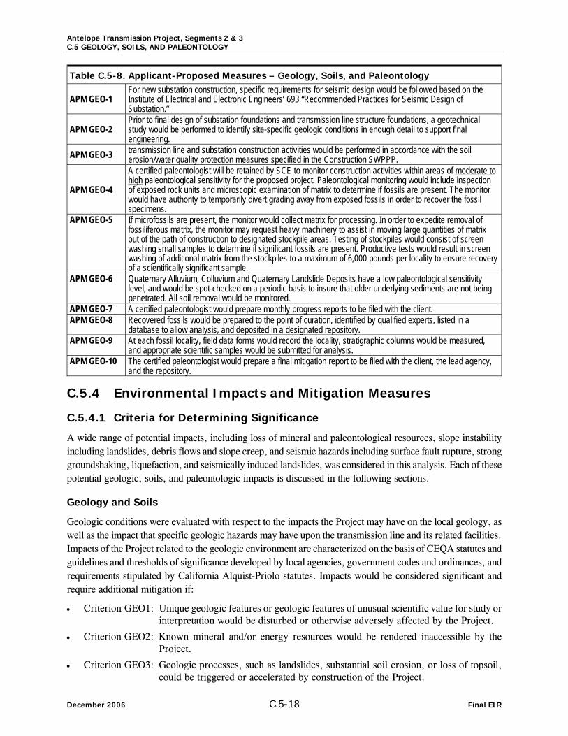
Antelope Transmission Project, Segments 2 & 3 C.5 GEOLOGY, SOILS, AND PALEONTOLOGY
December 2006 C.5-18 Final EIR
Table C.5-8. Applicant-Proposed Measures – Geology, Soils, and Paleontology
APM GEO-1 For new substation construction, specific requirements for seismic design would be followed based on the Institute of Electrical and Electronic Engineers’ 693 “Recommended Practices for Seismic Design of Substation.”
APM GEO-2 Prior to final design of substation foundations and transmission line structure foundations, a geotechnical study would be performed to identify site-specific geologic conditions in enough detail to support final engineering.
APM GEO-3 transmission line and substation construction activities would be performed in accordance with the soil erosion/water quality protection measures specified in the Construction SWPPP.
APM GEO-4
A certified paleontologist will be retained by SCE to monitor construction activities within areas of moderate to high paleontological sensitivity for the proposed project. Paleontological monitoring would include inspection of exposed rock units and microscopic examination of matrix to determine if fossils are present. The monitor would have authority to temporarily divert grading away from exposed fossils in order to recover the fossil specimens.
APM GEO-5 If microfossils are present, the monitor would collect matrix for processing. In order to expedite removal of fossiliferous matrix, the monitor may request heavy machinery to assist in moving large quantities of matrix out of the path of construction to designated stockpile areas. Testing of stockpiles would consist of screen washing small samples to determine if significant fossils are present. Productive tests would result in screen washing of additional matrix from the stockpiles to a maximum of 6,000 pounds per locality to ensure recovery of a scientifically significant sample.
APM GEO-6 Quaternary Alluvium, Colluvium and Quaternary Landslide Deposits have a low paleontological sensitivity level, and would be spot-checked on a periodic basis to insure that older underlying sediments are not being penetrated. All soil removal would be monitored.
APM GEO-7 A certified paleontologist would prepare monthly progress reports to be filed with the client. APM GEO-8 Recovered fossils would be prepared to the point of curation, identified by qualified experts, listed in a
database to allow analysis, and deposited in a designated repository. APM GEO-9 At each fossil locality, field data forms would record the locality, stratigraphic columns would be measured,
and appropriate scientific samples would be submitted for analysis. APM GEO-10 The certified paleontologist would prepare a final mitigation report to be filed with the client, the lead agency,
and the repository.
C.5.4 Environmental Impacts and Mitigation Measures
C.5.4.1 Criteria for Determining Significance
A wide range of potential impacts, including loss of mineral and paleontological resources, slope instability including landslides, debris flows and slope creep, and seismic hazards including surface fault rupture, strong groundshaking, liquefaction, and seismically induced landslides, was considered in this analysis. Each of these potential geologic, soils, and paleontologic impacts is discussed in the following sections.
Geology and Soils
Geologic conditions were evaluated with respect to the impacts the Project may have on the local geology, as well as the impact that specific geologic hazards may have upon the transmission line and its related facilities. Impacts of the Project related to the geologic environment are characterized on the basis of CEQA statutes and guidelines and thresholds of significance developed by local agencies, government codes and ordinances, and requirements stipulated by California Alquist-Priolo statutes. Impacts would be considered significant and require additional mitigation if:
• Criterion GEO1: Unique geologic features or geologic features of unusual scientific value for study or interpretation would be disturbed or otherwise adversely affected by the Project.
• Criterion GEO2: Known mineral and/or energy resources would be rendered inaccessible by the Project.
• Criterion GEO3: Geologic processes, such as landslides, substantial soil erosion, or loss of topsoil, could be triggered or accelerated by construction of the Project.

Antelope Transmission Project, Segments 2 & 3 C.5 GEOLOGY, SOILS, AND PALEONTOLOGY
Final EIR C.5-19 December 2006
• Criterion GEO4: High potential for earthquake-related ground rupture in the vicinity of major fault crossings would cause the Project to expose people or structures to potential risk of loss or injury.
• Criterion GEO5: High potential for seismically induced ground shaking, landslides, liquefaction, settlement, lateral spreading, and/or surface cracking would cause the Project to expose people or structures to potential risk of loss or injury.
• Criterion GEO6: Presence of corrosive soils or other unsuitable soils would cause the Project to expose people or structures to potential risk of loss or injury.
• Criterion GEO7: Potential of possible landslides on existing unstable slopes could damage the Project.
Paleontology
Determination of the “significance” of a fossil can only occur after a fossil has been found and identified by a qualified paleontologist. Until then, the actual significance is unknown. The most useful designation for paleontological resources in an EIR document is the “sensitivity” of a particular geologic unit. Sensitivity refers to the likelihood of finding significant fossils within a geologic unit. Categories of “sensitivity” are defined in Section C.5.1.4. Fossils are considered to be scientifically significant if they meet or potentially meet any one or more of the following criteria:
• Taxonomy – fossils that are scientifically judged to be important for representing rare or unknown taxa, such as defining a new species
• Evolution – fossils that are scientifically judged to represent important stages or links in evolutionary relationships, or fill gaps or enhance under-represented intervals in the stratigraphic record
• Biostratigraphy – fossils that are scientifically judged to be important for determining or constraining relative geologic (stratigraphic) age, or for use in regional to interregional stratigraphic correlation problems
• Paleoecology – fossils that are scientifically judged to be important for reconstructing ancient organism community structure and interpretation of ancient sedimentary environments
• Taphonomy – fossils that are scientifically judged to be exceptionally well or unusually or uniquely preserved, or are relatively rare in the stratigraphy.
In southern California, generally fossils of land-dwelling vertebrates are considered the most significant.
Impacts of the Project on paleontology would be considered significant and require additional mitigation if Project construction or operation would result in any of the following criteria being met:
• Criterion GEO8: Unique paleontological resource would be directly or indirectly destroyed by the Project.
C.5.4.2 Impact Analysis
The geologic, seismic, and paleontologic impacts of the proposed Project are discussed below under subheadings corresponding to each of the significance criteria presented in the preceding section. The analysis describes the impacts of the proposed Project related to geologic and seismic hazards, mineral resources, and paleontology and, for each criterion, determines whether implementation of the proposed Project would result in significant impacts.
C.5.4.2.1 Impact and Mitigation Summary
This section summarizes the conclusions of the impact analysis and associated mitigation measures presented in Section C.5.4.2.2. Table C.5-9 lists each impact identified for the proposed Project, along with the significance of each impact. Impacts are classified as Class I (significant, cannot be mitigated to a level that is less than significant), Class II (significant, can be mitigated to a level that is less than significant), Class III
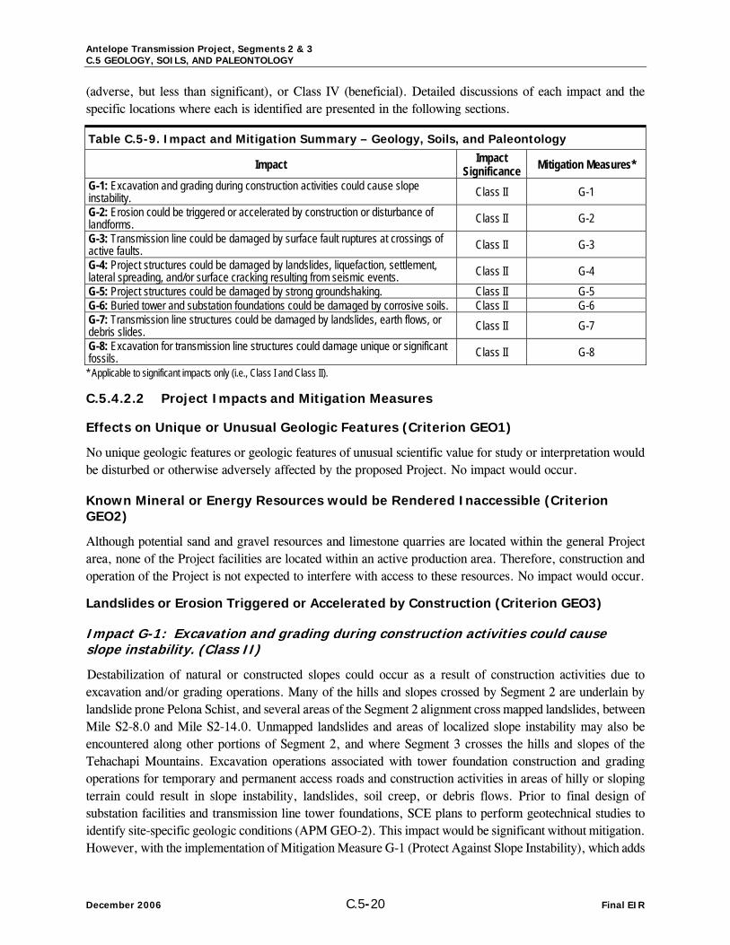
Antelope Transmission Project, Segments 2 & 3 C.5 GEOLOGY, SOILS, AND PALEONTOLOGY
December 2006 C.5-20 Final EIR
(adverse, but less than significant), or Class IV (beneficial). Detailed discussions of each impact and the specific locations where each is identified are presented in the following sections.
Table C.5-9. Impact and Mitigation Summary – Geology, Soils, and Paleontology
Impact Impact Significance Mitigation Measures*
G-1: Excavation and grading during construction activities could cause slope instability. Class II G-1 G-2: Erosion could be triggered or accelerated by construction or disturbance of landforms. Class II G-2 G-3: Transmission line could be damaged by surface fault ruptures at crossings of active faults. Class II G-3 G-4: Project structures could be damaged by landslides, liquefaction, settlement, lateral spreading, and/or surface cracking resulting from seismic events. Class II G-4 G-5: Project structures could be damaged by strong groundshaking. Class II G-5 G-6: Buried tower and substation foundations could be damaged by corrosive soils. Class II G-6 G-7: Transmission line structures could be damaged by landslides, earth flows, or debris slides. Class II G-7 G-8: Excavation for transmission line structures could damage unique or significant fossils. Class II G-8 * Applicable to significant impacts only (i.e., Class I and Class II).
C.5.4.2.2 Project Impacts and Mitigation Measures
Effects on Unique or Unusual Geologic Features (Criterion GEO1)
No unique geologic features or geologic features of unusual scientific value for study or interpretation would be disturbed or otherwise adversely affected by the proposed Project. No impact would occur.
Known Mineral or Energy Resources would be Rendered Inaccessible (Criterion GEO2)
Although potential sand and gravel resources and limestone quarries are located within the general Project area, none of the Project facilities are located within an active production area. Therefore, construction and operation of the Project is not expected to interfere with access to these resources. No impact would occur.
Landslides or Erosion Triggered or Accelerated by Construction (Criterion GEO3)
Impact G-1: Excavation and grading during construction activities could cause slope instability. (Class II)
Destabilization of natural or constructed slopes could occur as a result of construction activities due to excavation and/or grading operations. Many of the hills and slopes crossed by Segment 2 are underlain by landslide prone Pelona Schist, and several areas of the Segment 2 alignment cross mapped landslides, between Mile S2-8.0 and Mile S2-14.0. Unmapped landslides and areas of localized slope instability may also be encountered along other portions of Segment 2, and where Segment 3 crosses the hills and slopes of the Tehachapi Mountains. Excavation operations associated with tower foundation construction and grading operations for temporary and permanent access roads and construction activities in areas of hilly or sloping terrain could result in slope instability, landslides, soil creep, or debris flows. Prior to final design of substation facilities and transmission line tower foundations, SCE plans to perform geotechnical studies to identify site-specific geologic conditions (APM GEO-2). This impact would be significant without mitigation. However, with the implementation of Mitigation Measure G-1 (Protect Against Slope Instability), which adds

Antelope Transmission Project, Segments 2 & 3 C.5 GEOLOGY, SOILS, AND PALEONTOLOGY
Final EIR C.5-21 December 2006
specific requirements to the planned geotechnical investigations prior to final Project design, Impact G-1 would be reduced to a less-than-significant (Class II) level.
Mitigation Measure for Impact G-1
G-1 Protect Against Slope Instability. Design-level geotechnical investigations performed by the Applicant shall be performed by a licensed geologist or engineer and shall include evaluation of slope stability issues in areas of planned grading and excavation, and provide recommendations for development of grading and excavation plans. Based on the results of the geotechnical investigations, appropriate support and protection measures shall be designed and implemented to maintain the stability of slopes adjacent to newly graded or re-graded access roads and work areas during and after construction. These measures shall include, but are not limited to, retaining walls, visqueen, removal of unstable materials, and avoidance of highly unstable areas. SCE shall document compliance with this measure prior to the start of construction by submitting a report to the CPUC for review and approval. The report shall document the investigations and detail the specific support and protection measures that will be implemented.
Option A
The proposed alignment for Option A is situated nearby mapped landslides in the Pelona Schist. This impact would be significant without mitigation. However, with implementation of Mitigation Measure G-1 (Protect Against Slope Instability), Impact G-1 for Option A would be reduced to a less-than-significant (Class II) level.
Option B
The proposed alignment for Option B would traverse a mapped landslide in the Pelona Schist, where the route diverts from the proposed Segment 2 route. This impact would be significant without mitigation. However, with the implementation of Mitigation Measure G-1 (Protect Against Slope Instability), Impact G-1 for Option B would be reduced to a less-than-significant (Class II) level.
Impact G-2: Erosion could be triggered or accelerated by construction or disturbance of landforms. (Class II)
Excavation and grading for tower and substation foundations, work areas, and access roads could loosen soil or remove stabilizing vegetation and expose areas of loose soil. These areas, if not properly stabilized during construction, could be subject to increased soil loss and erosion by wind and stormwater runoff. Newly constructed and compacted engineered slopes can also undergo substantial erosion through dispersed sheet flow runoff. More concentrated runoff can result in the formation of small erosional channels and larger gullies, each compromising the integrity of the slope and resulting in significant soil loss. Portions of Segment 3 and most of Segment 2 are underlain by soils classified as having moderate to severe hazard of erosion on roads and trails. SCE has committed to perform transmission line and substation construction activities in accordance with the soil erosion/water quality protection measures specified in the Construction Storm Water Pollution Prevention Plan (SWPPP). In accordance with Section 402 of the federal Clean Water Act (CWA) and the State Water Resources Control Board (SWRCB), any construction project which disturbs one acre or more of ground surface must prepare a Construction SWPPP (SWRCB, 2006). The SWPPP would be prepared once the proposed Project is approved and after the necessary facilities are sited and designed, in order to ensure site-specific conditions are effectively addressed. All SWPPPs must include Best Management Practices (BMPs) for erosion and sediment control, as well as for construction waste handling and disposal (SWRCB, 2006). Furthermore, compliance APM GEO-3 would assure compliance with BMPs defined in the SWPPP during all aspects of construction. This impact would be significant without mitigation. However,

Antelope Transmission Project, Segments 2 & 3 C.5 GEOLOGY, SOILS, AND PALEONTOLOGY
December 2006 C.5-22 Final EIR
implementation of Mitigation Measure G-2 (Minimize Soil Erosion) ensures that potential impacts from erosion related to grading and use of access roads and work areas in areas of moderate to severe erosion potential during construction would be reduced to a less-than-significant (Class II) level.
Mitigation Measure for Impact G-2
G-2 Minimize Soil Erosion. The Construction SWPPP for the Project shall include Best Management Practices (BMPs) designed to minimize soil erosion along access roads and at work areas. Appropriate BMPs may include construction of water bars, grading road surfaces to direct flow away from natural slopes, use of soil stabilizers, and consistent maintenance of roads and culverts to maintain appropriate flow paths. Silt fences and straw bales installed during construction shall be removed to restore natural drainage during the cleanup and restoration phase of the project. Where access roads cross streams or drainages, they shall be built at or close to right angles to the streambeds and washes and culverts or rock crossings shall be used to cross streambeds and washes. Design of appropriate BMPs should be conducted by or under the direction of a qualified geologist or engineer.
Option A and Option B
The proposed alignments for Option A and Option B are underlain by soils classified as having moderate to severe hazard of erosion on roads and trails. With the implementation of Mitigation Measure G-2 (Minimize Soil Erosion), Impact G-2 for Options A and B would be the same as the proposed Project (Class II).
Earthquake-Related Ground Rupture (Criterion GEO4)
Impact G-3: Transmission line could be damaged by surface fault ruptures at crossings of active faults. (Class II)
Project facilities would be subject to hazards of surface fault rupture at crossings of active traces of the Garlock fault at approximately Mile S3-3.5 and of the San Andreas Fault between Mile S2-7.6 and Mile S2-8.2. Both of these faults are significant active faults with mapped Alquist-Priolo zones, as shown in Figure C.5-4, capable of multiple feet of offset. Fault crossings where multiple feet of displacement are expected along active faults are best crossed as overhead lines with towers placed well outside the fault zone to allow for the flex in the cables to absorb offset. This impact would be significant without mitigation. However, in addition to the geotechnical study required by APM GEO-2, Mitigation Measure G-3 (Minimize Project Structures within Active Fault Zones) shall be completed prior to final Project design for the Garlock fault and San Andreas fault crossing to minimize the length of transmission line within fault zones. With the implementation of Mitigation Measure G-3, potential impacts associated with overhead active fault crossings would be mitigated to a less-than-significant (Class II) level.
Mitigation Measure for Impact G-3
G-3 Minimize Project Structures within Active Fault Zones. Perform a geologic/geotechnical study to confirm location of active and potentially mapped traces of the Garlock and San Andreas faults where crossed by the Project alignment. Any active fault crossing shall be made as close to perpendicular to the fault as possible to make the transmission line cross the shortest distance within an active fault zone.Tower locations shall be adjusted as necessary to avoid placing tower footings on or across mapped fault traces. Towers on either side of a fault shall be designed to provide a significant amount of slack to allow for potential fault movement and ground surface displacement.

Antelope Transmission Project, Segments 2 & 3 C.5 GEOLOGY, SOILS, AND PALEONTOLOGY
Final EIR C.5-23 December 2006
Option A and Option B
With the implementation of Mitigation Measure G-3 (Minimize Project Structures within Active Fault ZonesMinimize Soil Erosion), Impact G-3 for Options A and B would be the same as the proposed Project (Class II).
Damage Related to Earthquake-Induced Phenomena (Criterion GEO5)
Impact G-4: Project structures could be damaged by landslides, liquefaction, settlement, lateral spreading, and/or surface cracking resulting from seismic events. (Class II)
There is a high potential for seismically induced landslides, liquefaction, settlement, surface cracking to cause damage to project structures at various locations. Liquefaction occurs in low-lying areas where saturated non-cohesive sediments are found. Slope instability and ground-cracking can occur anywhere. Areas that are most susceptible to earthquake-induced landslides and ground-cracking are sloping areas in poorly cemented or highly fractured rocks, areas underlain by loose, weak soils, and areas on or adjacent to existing landslide deposits.
The northern end of Segment 3 (where it crosses the Tehachapi Mountains) and the southern half of Segment 2 (crossing Portal Ridge, Ritter Ridge, and the Sierra Pelona) are located along hillsides or ridgelines in geologic units of moderate to steep slopes. Areas underlain by the landslide-prone Pelona Schist have a high possibility of seismic-induced ground failure in the form of landslides or ground-cracking.
Portions of Segment 2 are located in areas underlain by potentially liquefiable alluvial deposits and may be subject to liquefaction related phenomena during a seismic event, resulting in a significant impact. Potentially liquefiable deposits include the young alluvial deposits in Leona and Anaverde Valleys and Soledad Canyon, and in the alluvial and creek deposits of intervening drainages. Prior to final design of substation facilities and transmission line tower foundations, SCE plans to perform geotechnical studies to identify site-specific geologic conditions (APM GEO-2). This impact would be significant without mitigation. However, implementation of Mitigation Measure G-4 (Geotechnical Investigations for Liquefaction and Slope Instability) would add specific requirements to the planned geotechnical investigations prior to final Project design and would reduce potential impacts of seismically related ground failure along the Project route to a less-than-significant (Class II) level.
Mitigation Measure for Impact G-4
G-4 Geotechnical Investigations for Liquefaction and Seismic Slope Instability. Because seismically induced ground failure has the potential to damage or destroy Project components, the Applicant shall perform design-level geotechnical investigations specifically to assess the potential for liquefaction, seismic slope instability, and ground-cracking hazards to affect the approved Project and all associated facilities. Where these hazards are found to exist, appropriate engineering design and construction measures shall be incorporated into the Project designs. Such measures could include construction of pile foundations, ground improvement of liquefiable zones, installation of flexible bus connections, and incorporation of slack in cables to allow ground deformations without damage to structures.
Option A and Option B
Portions of Options A and B are located in areas underlain by potentially liquefiable alluvial deposits and may be subject to liquefaction related phenomena during a seismic event, resulting in a significant impact. Potentially liquefiable deposits include the young alluvial deposits in Leona and Anaverde Valleys and Soledad

Antelope Transmission Project, Segments 2 & 3 C.5 GEOLOGY, SOILS, AND PALEONTOLOGY
December 2006 C.5-24 Final EIR
Canyon, and in the alluvial and creek deposits of intervening drainages. With the implementation of Mitigation Measure G-4 (Geotechnical Investigations for Liquefaction and Slope Instability), Impact G-4 for Options A and B would be the same as the proposed Project (Class II).
Impact G-5: Project structures could be damaged by strong groundshaking. (Class II)
Moderate to strong groundshaking would be experienced along Segment 3 in the event of an earthquake on the faults in the Project area. Estimated peak ground accelerations (pgas) along Segment 3 range from 0.3 g to 0.6g, with the higher accelerations at the northern and southern ends of the alignment. Strong to severe groundshaking should be expected along Segment 2 in the event of an earthquake on the faults in the Project area. Estimated pgas along Segment 2 would range from 0.5g to 0.8g, with the highest accelerations in the vicinity of the San Andreas Fault Zone. Although appropriate tower design which accounts for lateral wind loads and conductor loads will likely exceed any creditable seismic loading, strong to severe seismically induced groundshaking could cause damage to project structures. The Project alignments would also be subject to groundshaking from any of the major faults in the region. While the shaking would be less severe from an earthquake that originates farther from the alignment, the effects, particularly on the ridgelines, could be damaging to Project structures.
It is likely that the Project facilities would be subjected to at least one moderate or larger earthquake occurring close enough to produce strong groundshaking in the Project area. SCE plans to perform geotechnical studies to identify site-specific geologic conditions prior to final design of substation facilities and transmission line tower foundations (APM GEO-2). This impact would be significant without mitigation. To reduce Impact G-5 to a less-than-significant level, Mitigation Measure G-5 (Reduce Effects of Groundshaking) shall be implemented prior to final Project design to ensure that people or structures are not exposed to hazards associated with strong seismic groundshaking. Mitigation Measure G-5 adds specific requirements to the geotechnical investigations planned in APM GEO-2 and design requirements to ensure that Impact G-5 is reduced to a less-than-significant level (Class II).
Mitigation Measure for Impact G-5
G-5 Reduce Effects of Groundshaking. The design-level geotechnical investigations performed by the Applicant shall include site-specific seismic analyses to evaluate the peak ground accelerations for design of Project components. The Applicant shall follow the Institute of Electrical and Electronics Engineers (IEEE) 693 “Recommended Practices for Seismic Design of Substations” which has specific requirements to mitigate the types of damage that equipment at substations have had in the past from such seismic activity. These design guidelines shall be implemented during construction of substation modifications. Substation control buildings shall be designed in accordance with the 2001 California Building Code for sites in Seismic Zone 4 with near-field factors.
Option A and Option B
Strong to severe groundshaking should be expected along Option A and Option B, in the event of an earthquake on the faults in the Project area. Estimated pgas along Options A and B would range from 0.5g to 0.8g, with the highest accelerations in the vicinity of the San Andreas Fault Zone. This impact would be the same as for the proposed Project. This impact would be significant without mitigation. With the implementation of Mitigation Measure G-5 (Reduce Effects of Groundshaking), Impact G-5 for Options A and B would be less than significant (Class II).
Antelope Transmission Project, Segments 2 & 3 C.5 GEOLOGY, SOILS, AND PALEONTOLOGY
Final EIR C.5-25 December 2006
Damage to Project Structures from Unsuitable soils (Criterion GEO7)
Impact G-6: Buried tower and substation foundations could be damaged by corrosive soils. (Class II)
Soils with moderate to high potential for corrosion exist along proposed route, as presented in Tables C.5-3 and C.5-4. Corrosive soils could have a detrimental effect on concrete and metals. Depending on the degree of corrosivity of subsurface soils, concrete and reinforcing steel in concrete structures and bare-metal structures exposed to these soils could deteriorate, eventually leading to structural failures. This impact would be significant without mitigation. However, implementation of Mitigation Measure G-6 (Geotechnical Studies for Corrosive Soils) prior to construction would reduce potential impacts from corrosive soils to a less-than-significant (Class II) level.
Mitigation Measure for Impact G-6
G-6 Geotechnical Studies for Corrosive Soils. In areas underlain by potentially corrosive soils, the design-level geotechnical studies performed by the Applicant shall identify the presence, if any, of potentially detrimental soil chemicals, such as chlorides and sulfates. Appropriate design measures for protection of reinforcement, concrete, and metal-structural components against corrosion shall be utilized, such as use of corrosion-resistant materials and coatings, increased thickness of Project components exposed to potentially corrosive conditions, and use of passive and/or active cathodic protection systems.
Option A and Option B
Impact G-6 for Options A and B would be the same as the proposed Project. With the implementation of Mitigation Measure G-6 (Geotechnical Studies for Corrosive Soils), Impact G-6 would be less than significant (Class II).
Damage to Transmission Line Support Structures from Landslides (Criterion GEO8)
Impact G-7: Transmission line structures could be damaged by landslides, earth flows, or debris slides. (Class II)
Portions of the Segment 2 alignment cross sloping areas which are underlain by geologic formations prone to landslides (Pelona Schist). Portions of the alignment also traverse existing landslides or are situated nearby existing landslides. Slope instability including landslides, earth flows, and debris flows has the potential to undermine foundations, cause distortion and distress to overlying structures, and displace or destroy Project components. This impact would be significant without mitigation. However, potential impacts associated with slope instability would be mitigated to a less-than-significant (Class II) level with implementation of Mitigation Measure G-7 (Geotechnical Surveys for Landslides) prior to Project construction.
Mitigation Measure for Impact G-7
G-7 Geotechnical Surveys for Landslides. The design-level geotechnical investigation performed by the Applicant shall include detailed surveys to evaluate the potential for unstable slopes, landslides, earth flows, and debris flows along the approved transmission line route and in the vicinity of other Project facilities. Based on these surveys, approved Project facilities shall be located away from known landslides, very steep hillsides, debris-flow source areas, the mouths of steep sidehill drainages, and the mouths of canyons that drain steep terrain. Where these landslide hazard areas cannot be avoided, appropriate engineering design and construction measures shall be incorporated into the Project designs to minimize potential for damage to Project facilities.

Antelope Transmission Project, Segments 2 & 3 C.5 GEOLOGY, SOILS, AND PALEONTOLOGY
December 2006 C.5-26 Final EIR
Option A and Option B
Impact G-7 for Options A and B would be the same as the proposed Project. With the implementation of Mitigation Measure G-7 (Geotechnical Surveys for Landslides), Impact G-7 would be less than significant (Class II).
Directly or Indirectly Destroy a Unique Paleontological Resource (Criterion 9)
Impact G-8: Excavation for transmission line structures could damage unique or significant fossils. (Class II)
Several fossil-bearing geologic formations with high sensitivity are located in the Project area, as discussed in Section C.5.1.4. SCE has proposed APMs GEO- 4 through GEO-10 to avoid impacts to paleontological resources, which would require that certified paleontologist would be retained by SCE to supervise monitoring of construction excavations in areas of moderate to high paleontologic sensitivity and to produce a mitigation plan for the proposed Project. Paleontological monitoring would include inspection of exposed rock units and microscopic examination of matrix to determine if fossils are present. The monitor would have authority to temporarily divert grading away from exposed fossils in order to recover the fossil specimens. A final mitigation report would be prepared by the certified paleontologist to be filed with the client, the CPUC, and the designated repository for any recovered fossils. This impact would be significant without mitigation. However, implementation of Mitigation Measure G-8 (Protect Paleontological Resources) would reinforce APMs GEO- 4 through GEO-10 and effectively reduce this potential impact to a less-than-significant (Class II) level.
Mitigation Measure for Impact G-8
G-8 Protect Paleontological Resources. The certified paleontological monitor retained by SCE to supervise monitoring of construction activities shall be responsible for the following:
• Monitoring shall be conducted were excavation is being conducted in geologic units of moderate to high sensitivity. Monitoring need not be conducted where excavation is being conducted in geologic units with zero sensitivity, such as the Pelona Schist and granitic and other igneous formations.
• If fossils are present in the construction area, then grading shall be temporarily diverted away from exposed fossils in order to recover the fossil specimens.
• If microfossils are present in the construction area, the monitor shall collect matrix for processing. In order to expedite removal of fossiliferous matrix, the monitor may request heavy machinery to assist in moving large quantities of matrix out of the path of construction to designated stockpile areas.
• Stockpiles shall be tested by screen washing small samples to determine if significant fossils are present. Productive tests shall result in screen washing of additional matrix from the stockpiles to a maximum of 6,000 pounds per locality to ensure recovery of a scientifically significant sample.
• Young Quaternary Alluvium, Colluvium, and Quaternary Landslide Deposits, which have a low paleontological sensitivity level, shall be spot-checked on a periodic basis to insure that older underlying sediments are not being penetrated.
• Recovered fossils shall be prepared to the point of curation, identified by qualified experts, listed in a database to allow analysis, and deposited in a designated repository.
• At each fossil locality, field data forms shall record the locality, stratigraphic columns shall be measured, and appropriate scientific samples submitted for analysis.
• A monthly progress report shall be prepared by the supervising paleontological monitor and filed with the client. A final mitigation report shall be filed with the client, the lead agency, and the repository.

Antelope Transmission Project, Segments 2 & 3 C.5 GEOLOGY, SOILS, AND PALEONTOLOGY
Final EIR C.5-27 December 2006
Option A and Option B
Impact G-8 for Options A and B would be the same as the proposed Project. With the implementation of Mitigation Measure G-8 (Protect Paleontological Resources), Impact G-8 would be less than significant (Class II).
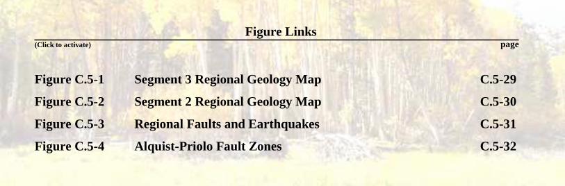
Figure Links (Click to activate) page
Figure C.5-1 Segment 3 Regional Geology Map C.5-29
Figure C.5-2 Segment 2 Regional Geology Map C.5-30
Figure C.5-3 Regional Faults and Earthquakes C.5-31
Figure C.5-4 Alquist-Priolo Fault Zones C.5-32