c-nav gps system & the seamless vertical datum gps services group c&c technologies, inc.,...
TRANSCRIPT

C-Nav GPS System & the C-Nav GPS System & the Seamless Vertical DatumSeamless Vertical DatumC-Nav GPS System & the C-Nav GPS System & the Seamless Vertical DatumSeamless Vertical Datum
GPS Services GroupC&C Technologies, Inc., (Lafayette, La)
www.cctechnol.com

Real Time Gipsy (RTG)Real Time Gipsy (RTG)
• Current release provides sub-meter level Current release provides sub-meter level horizontal accuracies.horizontal accuracies.
• Version 12.2 (beta) test indicates decimeter Version 12.2 (beta) test indicates decimeter level horizontal accuracy.level horizontal accuracy.
• We will be discussing Version 12.2We will be discussing Version 12.2

The C-Nav RTG MethodologyThe C-Nav RTG Methodology
Does not use the ‘traditional’ (RTCM) Does not use the ‘traditional’ (RTCM) measurement domain measurement domain or or position domainposition domain correction methods, nor is it RTK.correction methods, nor is it RTK.
Corrects each source of error.Corrects each source of error.
Broadcasts correctors for orbits and Broadcasts correctors for orbits and satellite clocks.satellite clocks.
Dual-frequency code and carrier phase Dual-frequency code and carrier phase measurement are used to form measurement are used to form pseudoranges free from ionospheric pseudoranges free from ionospheric delays.delays.
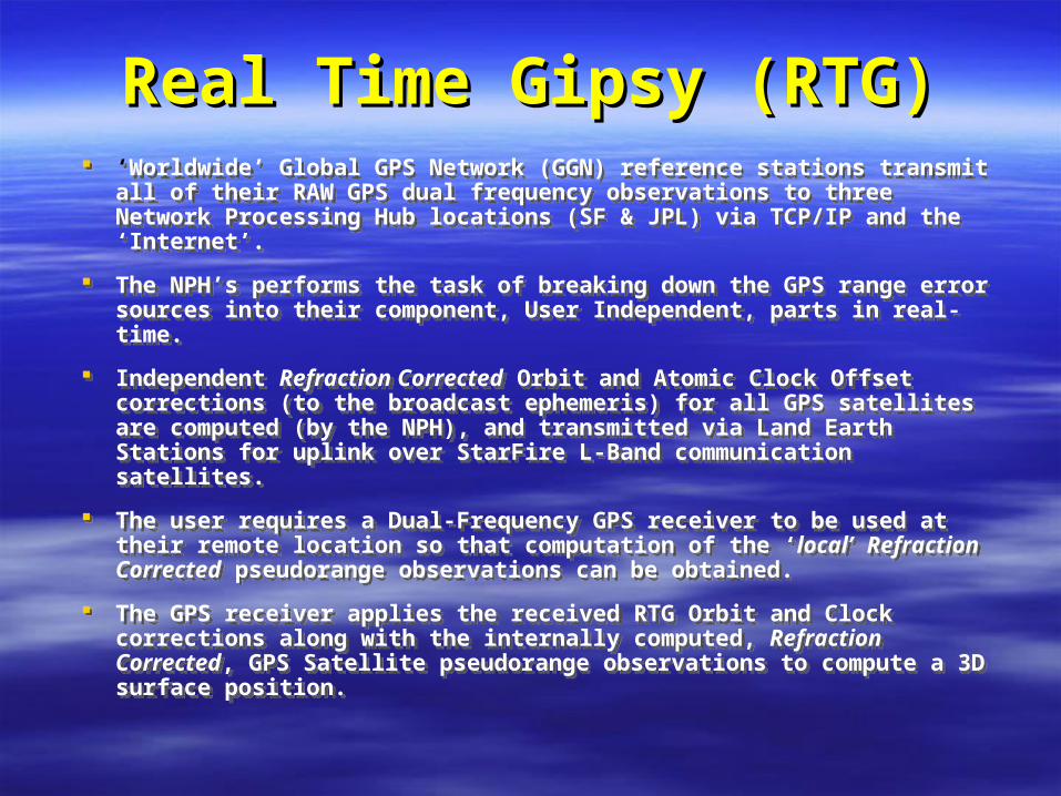
Real Time Gipsy (RTG)Real Time Gipsy (RTG) ‘Worldwide’ Global GPS Network (GGN) reference stations transmit
all of their RAW GPS dual frequency observations to three Network Processing Hub locations (SF & JPL) via TCP/IP and the ‘Internet’.
The NPH’s performs the task of breaking down the GPS range error sources into their component, User Independent, parts in real-time.
Independent Refraction Corrected Orbit and Atomic Clock Offset corrections (to the broadcast ephemeris) for all GPS satellites are computed (by the NPH), and transmitted via Land Earth Stations for uplink over StarFire L-Band communication satellites.
The user requires a Dual-Frequency GPS receiver to be used at their remote location so that computation of the ‘local’ Refraction Corrected pseudorange observations can be obtained.
The GPS receiver applies the received RTG Orbit and Clock corrections along with the internally computed, Refraction Corrected, GPS Satellite pseudorange observations to compute a 3D surface position.
‘Worldwide’ Global GPS Network (GGN) reference stations transmit all of their RAW GPS dual frequency observations to three Network Processing Hub locations (SF & JPL) via TCP/IP and the ‘Internet’.
The NPH’s performs the task of breaking down the GPS range error sources into their component, User Independent, parts in real-time.
Independent Refraction Corrected Orbit and Atomic Clock Offset corrections (to the broadcast ephemeris) for all GPS satellites are computed (by the NPH), and transmitted via Land Earth Stations for uplink over StarFire L-Band communication satellites.
The user requires a Dual-Frequency GPS receiver to be used at their remote location so that computation of the ‘local’ Refraction Corrected pseudorange observations can be obtained.
The GPS receiver applies the received RTG Orbit and Clock corrections along with the internally computed, Refraction Corrected, GPS Satellite pseudorange observations to compute a 3D surface position.
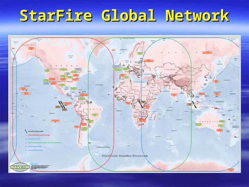
StarFire Global NetworkStarFire Global Network

RTG Reference Sites RTG Reference Sites Global Network (26+)Global Network (26+)
RTG Reference Sites RTG Reference Sites Global Network (26+)Global Network (26+)
Brewster, USA Brewster, USA Cordoba, ArgentinaCordoba, Argentina Christiansted,Virgin IslandsChristiansted,Virgin Islands Fairbanks, USAFairbanks, USA Galapagos Island, EcuadorGalapagos Island, Ecuador Greenbelt, USAGreenbelt, USA Goldstone, USAGoldstone, USA Dededo, GuamDededo, Guam Krugersdorp, South AfricaKrugersdorp, South Africa Bangalore, IndiaBangalore, India JPL Pasadena, USAJPL Pasadena, USA Kokee Park, USAKokee Park, USA Robledo, SpainRobledo, Spain
Ross Island, AntarcticaRoss Island, Antarctica Mauna Kea, USAMauna Kea, USA Moscow, RussiaMoscow, Russia Franceville, GabonFranceville, Gabon Norilsk, RussiaNorilsk, Russia Lamont, USALamont, USA Quezon City, PhillipinesQuezon City, Phillipines Bishkek, KryghystanBishkek, Kryghystan Santiago, ChileSantiago, Chile Tidbinbilla, AustraliaTidbinbilla, Australia USNO, USAUSNO, USA Usuda, JapanUsuda, Japan Yakutsk, Russia Yakutsk, Russia

C-Nav GPS User SystemC-Nav GPS User SystemC-Nav GPS User SystemC-Nav GPS User System
Basic System Hardware ‘Bundle’:Basic System Hardware ‘Bundle’:– 1 x C-Nav GPS Receiver1 x C-Nav GPS Receiver– 1 x C-Nav Control Display 1 x C-Nav Control Display
Unit (CnC D.U.)Unit (CnC D.U.)– 1 x C-Nav GPS Receiver 1 x C-Nav GPS Receiver
Data and Power Y-CableData and Power Y-Cable– 1 x DC Power Cable1 x DC Power Cable– 1 x Power Supply1 x Power Supply– 1 x C-Nav Operations 1 x C-Nav Operations
ManualManual– 1 x Software Utilities1 x Software Utilities

C-Nav GPS Receiver DesignC-Nav GPS Receiver DesignC-Nav GPS Receiver DesignC-Nav GPS Receiver Design
Multi-function L-Band antennaMulti-function L-Band antenna
12 channel dual-frequency, geodetic grade GPS 12 channel dual-frequency, geodetic grade GPS engineengine
L-Band communications receiver and embedded L-Band communications receiver and embedded microprocessormicroprocessor
Patented multi-path reduction signal processing Patented multi-path reduction signal processing capability and P code recovery algorithmcapability and P code recovery algorithm
Dual-frequency code and carrier phase Dual-frequency code and carrier phase measurement are used to form smooth refraction measurement are used to form smooth refraction corrected code pseudorangescorrected code pseudoranges
Compact size and integrated package designCompact size and integrated package design

C-Nav FeaturesC-Nav FeaturesC-Nav FeaturesC-Nav Features ‘‘Global corrected’ GPS Positioning ( RTG, WCT & WAAS )Global corrected’ GPS Positioning ( RTG, WCT & WAAS )
1Hz NMEA Msgs ( GGA, GLL, GSA, GST, RMC, VTG, ZDA )1Hz NMEA Msgs ( GGA, GLL, GSA, GST, RMC, VTG, ZDA )
Proprietary NMEA Data Msgs ( SATS, NAVQ, RXQ, NETQ )Proprietary NMEA Data Msgs ( SATS, NAVQ, RXQ, NETQ )
RTCM Output ( Standard RTCM Type 1 PRC – every 5 seconds )RTCM Output ( Standard RTCM Type 1 PRC – every 5 seconds )
Dual Frequency, Geodetic GPS Engine to resolve local Dual Frequency, Geodetic GPS Engine to resolve local Ionospheric delay observation errorsIonospheric delay observation errors
Multipath Mitigation AlgorithmMultipath Mitigation Algorithm
Rugged and waterproof Single Integrated PackageRugged and waterproof Single Integrated Package
Low Power Consumption ( < 10 Watts – 9v to 40v d.c.)Low Power Consumption ( < 10 Watts – 9v to 40v d.c.)
5Hz positioning and data output ( w/o CnC Display Unit )5Hz positioning and data output ( w/o CnC Display Unit )
Automatic Restart based on last operating configurationAutomatic Restart based on last operating configuration
‘‘Global corrected’ GPS Positioning ( RTG, WCT & WAAS )Global corrected’ GPS Positioning ( RTG, WCT & WAAS )
1Hz NMEA Msgs ( GGA, GLL, GSA, GST, RMC, VTG, ZDA )1Hz NMEA Msgs ( GGA, GLL, GSA, GST, RMC, VTG, ZDA )
Proprietary NMEA Data Msgs ( SATS, NAVQ, RXQ, NETQ )Proprietary NMEA Data Msgs ( SATS, NAVQ, RXQ, NETQ )
RTCM Output ( Standard RTCM Type 1 PRC – every 5 seconds )RTCM Output ( Standard RTCM Type 1 PRC – every 5 seconds )
Dual Frequency, Geodetic GPS Engine to resolve local Dual Frequency, Geodetic GPS Engine to resolve local Ionospheric delay observation errorsIonospheric delay observation errors
Multipath Mitigation AlgorithmMultipath Mitigation Algorithm
Rugged and waterproof Single Integrated PackageRugged and waterproof Single Integrated Package
Low Power Consumption ( < 10 Watts – 9v to 40v d.c.)Low Power Consumption ( < 10 Watts – 9v to 40v d.c.)
5Hz positioning and data output ( w/o CnC Display Unit )5Hz positioning and data output ( w/o CnC Display Unit )
Automatic Restart based on last operating configurationAutomatic Restart based on last operating configuration
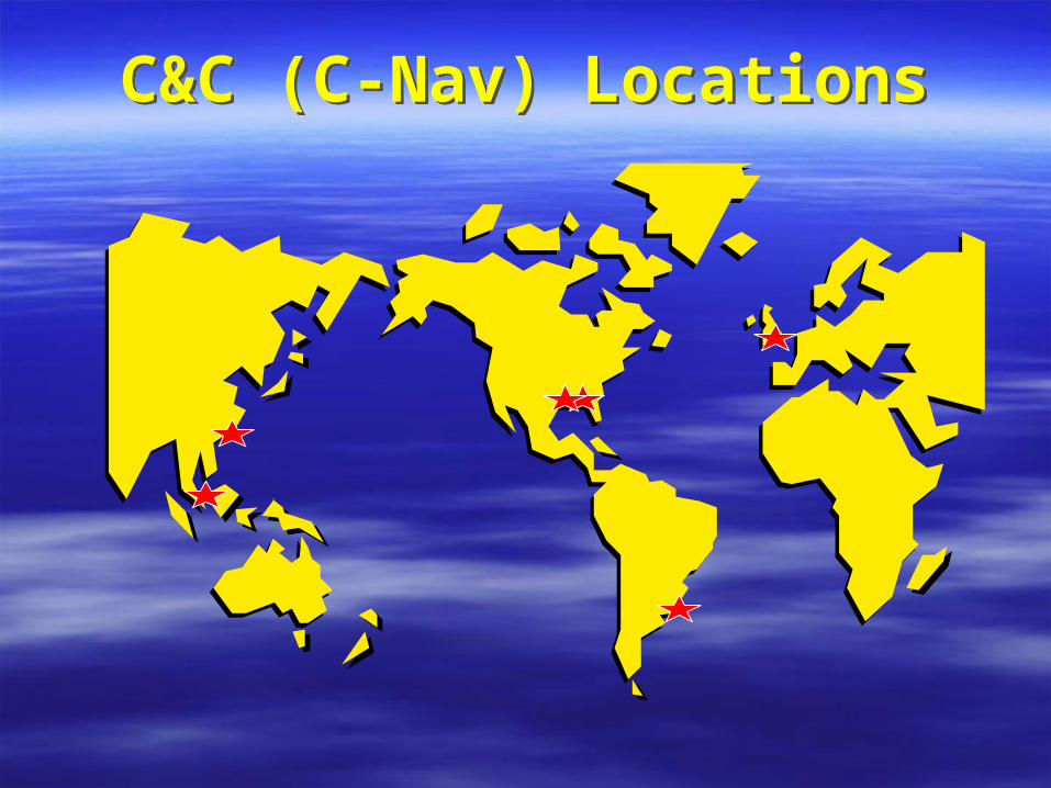
C&C (C-Nav) LocationsC&C (C-Nav) Locations

Vertical AccuracyVertical Accuracy
•IHO SP 57, 1987
•0.3 meters at 90% confidence
•Assuming Gaussian:
0.36 meters at 95% confidence
•IHO SP 57, 1987
•0.3 meters at 90% confidence
•Assuming Gaussian:
0.36 meters at 95% confidence

Vertical AccuracyVertical Accuracy
•IHO S 57, 1998, category 1:
Depth error of 0.5 m at 95% confidence.
•Assume sounding error of 0.36 meters at 95%:
Allowable “Tide” 0.35 meters at 95% confidence.
•IHO S 57, 1998, category 1:
Depth error of 0.5 m at 95% confidence.
•Assume sounding error of 0.36 meters at 95%:
Allowable “Tide” 0.35 meters at 95% confidence.

Vertical AccuracyVertical Accuracy
•IHO S 57, 1998, category “special”:
Depth error of 0.25 m at 95% confidence.
•Assume sounding error of 0.15 meters at 95%:
Allowable “Tide” 0.20 meters at 95% confidence.
•IHO S 57, 1998, category “special”:
Depth error of 0.25 m at 95% confidence.
•Assume sounding error of 0.15 meters at 95%:
Allowable “Tide” 0.20 meters at 95% confidence.

Vertical AccuracyVertical Accuracy
•NOS Specifications and Deliverables
January 2002:
Tidal errors range from 0.2 m to 0.45 m
at 95% confidence.
•NOS Specifications and Deliverables
January 2002:
Tidal errors range from 0.2 m to 0.45 m
at 95% confidence.
Vertical AccuracyVertical Accuracy
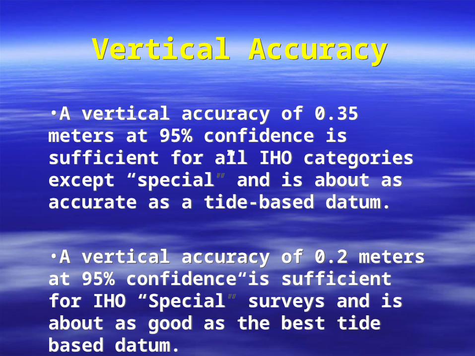
•A vertical accuracy of 0.35 meters at 95% confidence is sufficient for all IHO categories except “special” and is about as accurate as a tide-based datum.
•A vertical accuracy of 0.2 meters at 95% confidence is sufficient for IHO “Special” surveys and is about as good as the best tide based datum.
•A vertical accuracy of 0.35 meters at 95% confidence is sufficient for all IHO categories except “special” and is about as accurate as a tide-based datum.
•A vertical accuracy of 0.2 meters at 95% confidence is sufficient for IHO “Special” surveys and is about as good as the best tide based datum.

Figure 1: SD = 0.386 m
Figure 1: SD = 0.386 m
Figure 2: SD 0.277Figure 2: SD 0.277
Figure 3: SD = 0.197 mFigure 3: SD = 0.197 m

High MultipathHigh Multipath

RTG
3352822.00
3352822.50
3352823.00
3352823.50
3352824.00
3352824.50
3352825.00
3352825.50
3352826.00
610771.50 610772.00 610772.50 610773.00 610773.50 610774.00 610774.50 610775.00
1st Hour 2nd Hour 3rd Hour 4th Hour Reference Point Craig's Point 1st Avg. 2nd Avg. 3rd Avg. 4th Avg.

Good DataGood Data
Max HDOP = 3, max speed = 6 m/s; Discard stand alone GPS.Max HDOP = 3, max speed = 6 m/s; Discard stand alone GPS.
95% of data is within 0.41 meters of the mean. 95% of data is within 0.41 meters of the mean.

Good DataGood Data

How Good?
•Vertical accuracy of about 0.41 meters at 95%.
•About the same as NOS zoned tides in the most difficult areas.
•Can be used for IHO Category 1, but sounding errors must be limited to 0.3 meter at 95%.
•Further testing needed to confirm accuracy and understand restrictions.
How Good?
•Vertical accuracy of about 0.41 meters at 95%.
•About the same as NOS zoned tides in the most difficult areas.
•Can be used for IHO Category 1, but sounding errors must be limited to 0.3 meter at 95%.
•Further testing needed to confirm accuracy and understand restrictions.

Conclusions
•Vertical accuracy of about 0.41 meters
•Multipath needs to be controlled.
•About ten minutes to sub-meter data.
•About 2 hours to decimeter data.
Conclusions
•Vertical accuracy of about 0.41 meters
•Multipath needs to be controlled.
•About ten minutes to sub-meter data.
•About 2 hours to decimeter data.