c-130h2 pilot conversion notes references flight …1 c-130h2 pilot conversion notes references...
TRANSCRIPT
1
C-130H2 Pilot Conversion Notes
References
Flight Manual: T.O. 1C-130H-1
Performance Manual: T.O. 1C-130H-1-1
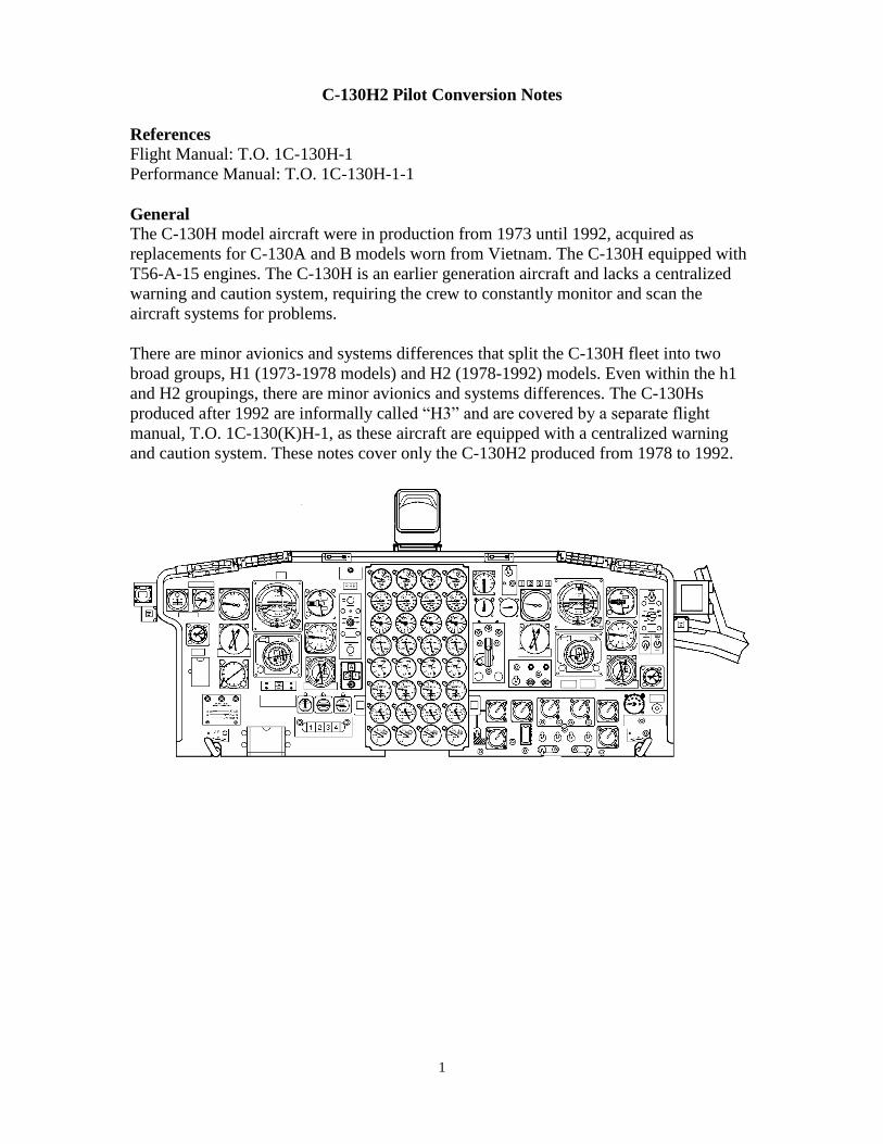
General
The C-130H model aircraft were in production from 1973 until 1992, acquired as
replacements for C-130A and B models worn from Vietnam. The C-130H equipped with
T56-A-15 engines. The C-130H is an earlier generation aircraft and lacks a centralized
warning and caution system, requiring the crew to constantly monitor and scan the
aircraft systems for problems.
There are minor avionics and systems differences that split the C-130H fleet into two
broad groups, H1 (1973-1978 models) and H2 (1978-1992) models. Even within the h1
and H2 groupings, there are minor avionics and systems differences. The C-130Hs
produced after 1992 are informally called “H3” and are covered by a separate flight
manual, T.O. 1C-130(K)H-1, as these aircraft are equipped with a centralized warning
and caution system. These notes cover only the C-130H2 produced from 1978 to 1992.
2
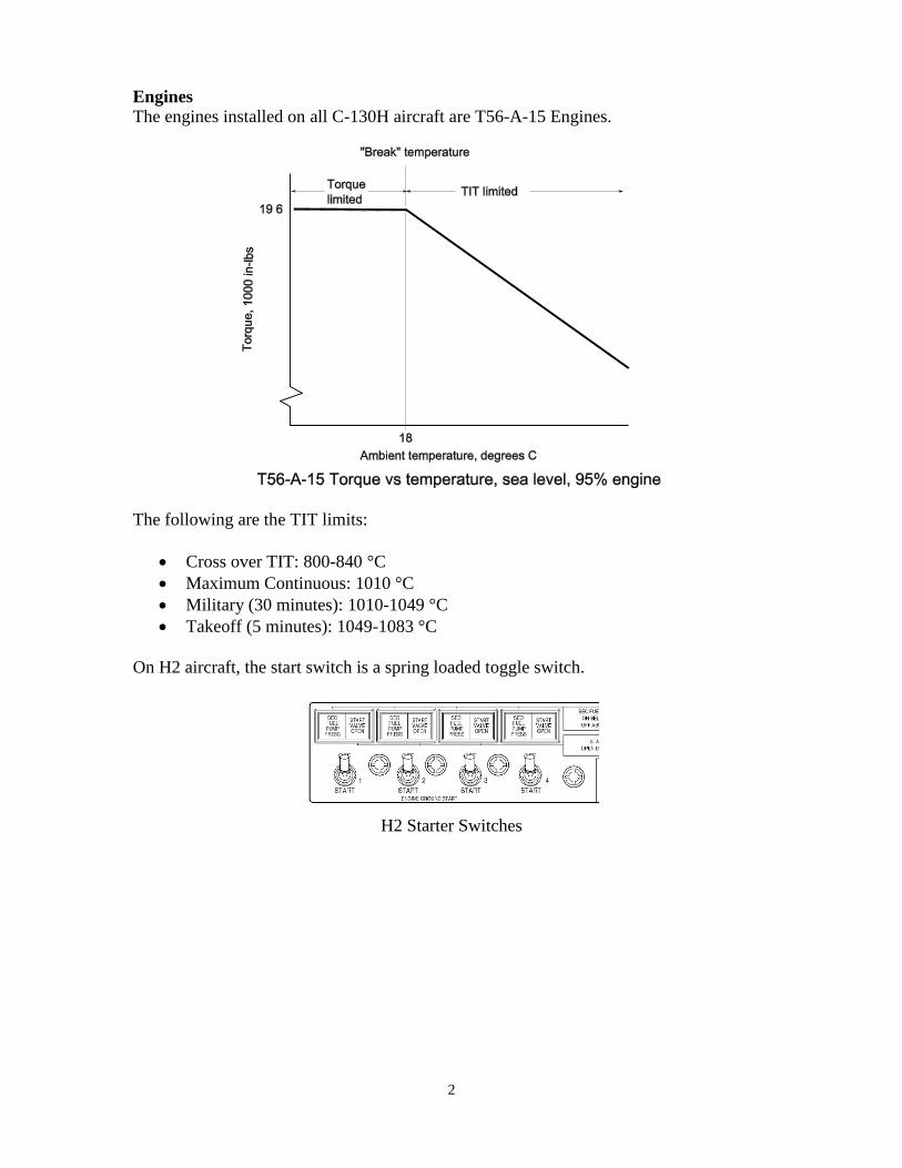
Engines
The engines installed on all C-130H aircraft are T56-A-15 Engines.
The following are the TIT limits:
Cross over TIT: 800-840 °C
Maximum Continuous: 1010 °C
Military (30 minutes): 1010-1049 °C
Takeoff (5 minutes): 1049-1083 °C
On H2 aircraft, the start switch is a spring loaded toggle switch.
H2 Starter Switches

3
Aircraft prior to 85-0035 do not have oil cooler augmentation, so the oil temperature
must be closely monitored for overheating when using reverse thrust during taxi.
Oil cooler augmentation is installed on later model H2s (aircraft 85-0035 and later), and
uses 14th stage compressor bleed air through an ejector to increase the air flow across the
engine oil coolers. For the oil cooler augmentation system to operate, the following
conditions must be met:
Oil cooler switch must be in AUTO
Oil cooler flap must be at least 90 percent open
Throttle must be in the ground range
Engine start switch must be in the OFF position.
Because the oiler cooler augmentation uses bleed air, it can be a significant load on the
engine during:
Low speed ground idle, and
During reverse operations at hot temperatures/high density altitudes.

4
It is a good technique to turn off the oil cooler augmentation on hot days when landing if
reverse will be used, and when operating all engines in low speed ground idle.
Engine Low Oil Quality Indicator
On the left side of the engine stack is an ENG LOW QUANTITY warning light. Each
engine power section and reduction gear box share a common oil system, feed by a 12
gallon tank. Each engine has an individual oil quantity indicator. If any engine’s quantity
drops below 4 gallons, the ENG LOW QUANTITY light on the left of the engine stack
will illuminate. The engine gages must be consulted to determine which engine has the
low quantity.
5
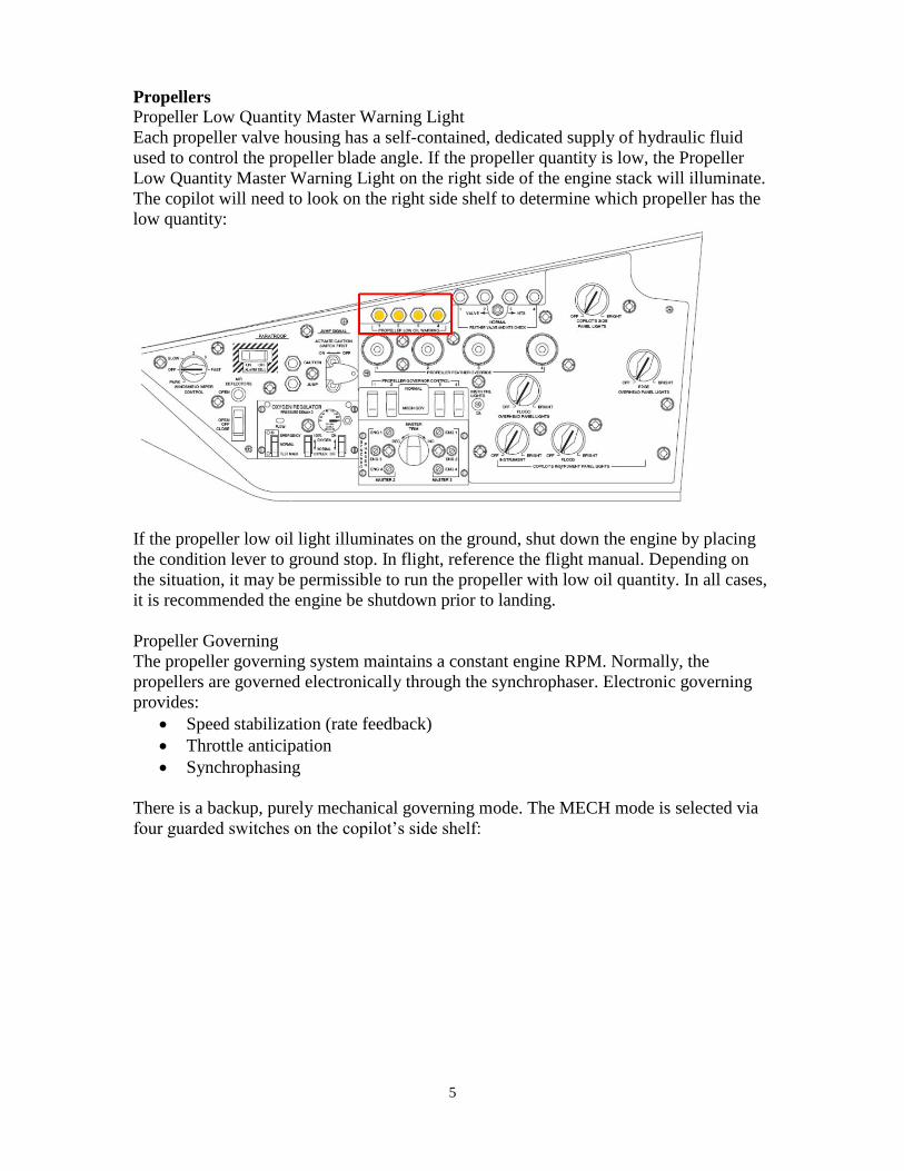
Propellers
Propeller Low Quantity Master Warning Light
Each propeller valve housing has a self-contained, dedicated supply of hydraulic fluid
used to control the propeller blade angle. If the propeller quantity is low, the Propeller
Low Quantity Master Warning Light on the right side of the engine stack will illuminate.
The copilot will need to look on the right side shelf to determine which propeller has the
low quantity:
If the propeller low oil light illuminates on the ground, shut down the engine by placing
the condition lever to ground stop. In flight, reference the flight manual. Depending on
the situation, it may be permissible to run the propeller with low oil quantity. In all cases,
it is recommended the engine be shutdown prior to landing.
Propeller Governing
The propeller governing system maintains a constant engine RPM. Normally, the
propellers are governed electronically through the synchrophaser. Electronic governing
provides:
Speed stabilization (rate feedback)
Throttle anticipation
Synchrophasing
There is a backup, purely mechanical governing mode. The MECH mode is selected via
four guarded switches on the copilot’s side shelf:

6
The propellers on the C-130 are not counterweighted, and the blade angle will flatten
from centrifugal force if hydraulic pressure is not maintained on the blade change
mechanism. The propellers must be driven towards feather via valve housing hydraulic
pressure. An electrically powered auxiliary feather motor is used to feather the propeller.
When the propeller is signaled to feather, either via the condition lever or fire handle, the
auxiliary feather motor operates. Operation of the auxiliary feather motor is indicated to
the aircrew via solenoid-actuated feather buttons. When the auxiliary feather motor is
operating, the feather override button is pulled down and a light illuminates. The crew
can pull the feather motor override button out to shut off the feather motor, or push the
button in to complete the feather cycle.
Limitations on use of the auxiliary feather motor:
Must be operative for flight
Duty cycle: 1 minute on, 1 minute OFF, not to exceed 2 minutes on in 30 minutes
Reverse to feather static feather cycle must be completed in 25 seconds.
Must pop out within 6 seconds of completing the feather cycle

7
The feather valve and NTS test switch is used to verify operation of the feather valve
(VALVE position) and NTS circuits (NTS position). The NTS position is used during
engine shutdown to check the operation of the NTS.

8
Auxiliary Power Unit
The C-130H has an auxiliary power unit (APU), located in the forward wheel well. On
the ground, the APU can provide bleed air for starting and AC electrical power only to
the essential AC bus. In flight, the APU should start and operate between -1,000 and
20,000 feet pressure altitude and can provide electrical power to the essential AC bus.
Attempting to use APU bleed air in flight will probably result in an APU fire indication.
APU controls are located on the overhead panel, and are normally operated by the FE.
The APU has three indicator lights:
DOOR OPEN (red): Indicates the APU inlet door is open 35 degrees on ground
15 in flight.
START (amber: Indicated APU in start, turns off at 35% APU RPM
ON SPEED (green): Indicated APU on speed, illuminates at 95 % APU RPM
The APU fuel supply is via gravity feed from the No 2 main tank surge box. If No 2 main
tank fuel quantity is less than 2,000 pounds, the No 2 main tank boost pump should be
operated to ensure the surge box remains full. The fuel to the APU is shut off by moving
either the APU control switch to STOP or pulling the APU fire handle.
APU starter duty cycle is 1 minute ON, 4 minutes OFF
The APU must be operated for 1 minute prior to applying a load (4 minutes during cold
weather operations [OAT < 32º F]).
Minimum operating bleed pressure from the APU is 35 psi.
During ground operation, monitor the leading edge temperature indicators. A
rise in temperature indicates that an anti-icing valve is open. APU bleed air
must be shut off to prevent damage to heated surface.

9
Fire/Overheat/Turbine Overheat
When a FIRE is detected in an engine nacelle or with the APU, the appropriate two
bottom lights in the respective fire handle will illuminate STEADY.
If there is a TURBINE overheat (over temperature in hot section) detected in the nacelle
aft of the fire wall, the top two red lights in the fire handle will FLASH.
Operation of the turbine overheat test switch should not exceed 30 seconds.
Do not test again for a period of 1 minute. Long, continuous testing may result
in failure of the system.
Note The test switch will only check circuit continuity and that the switch is
functioning properly. Even though all indicator lights illuminate, this does not
indicate the detectors are properly set or even operating.
There is a FIRE cue light on the pilot’s instrument panel above the Flight Director Mode
Select Switch panel that illuminates STEADY for engine FIRES and FLASHES for
TURBINE overheat:

10
Nacelle overheat: Dedicated lights above co-pilot’s airspeed indicator.
Note The test switch will only check circuit continuity and that the switch is
functioning properly. Even though all indicator lights illuminate, this does not
indicate the detectors are properly set or even operating.

11
Bleed Air
The C-130H engines have bleed air regulators instead of the simple bleed air valves used
on the C-130E. The bleed air regulators are controlled via a 3 position switch for each
engine:
OFF
ON: Regulate to a bleed manifold pressure of 45 PSI
OVRD (override), provide a bleed manifold pressure of 70 PSI. The OVRD
position is used for engine start.
The engineer confirms operation of the bleed regulators by watching for torque decrease
(opening)/increase (closing).
Bleed air sources:
Engines (4) 14th stage compressor, minimum pressure is 70 psi.
APU (1) minimum pressure is 35 psi.
Bleed Loads:
Engine starters
Pressurization/air-conditioning (2 packs, one for flight deck, one for cargo area)
Wing and empennage anti-icing
Engine Anti-icing (inlet air ducts, oil cooler scoops, inlet guide vanes)
Urinal ejectors (aircraft prior to 83-0486)
Oil Cooler Augmentation (aircraft 85-0035 and later)
H2 aircraft have an electrically operated bleed air divider valve in lieu of wing isolation
valves.
Preflight Bleed air check using APU bleed air to pressurize:
Minimum system pressure: 35 psi
Mimimum time to drop from 30 to 15 psi once the APU bleed air valve switch is
closed:
o Aircraft prior to 83-0486: 10 seconds.
o Aircraft 85-0035 and later: 16 seconds

12
Electrical
The electrical system is breaks down into three sub-systems:
AC powered system
Secondary AC system
DC system
AC Electrical Sources
AC Electrical Sources
(4) 40 KVA engine driven generators
(1) 40 KVA APU generator
The external AC power switch automatically goes to OFF when the APU generator
switch is place to ON,or if nay engine driven generator is on line, regardless of generator
operation.
DC Electrical Sources
Main battery (24 Volt)
INS battery (24 Volt)
The AC powered system is three phase, 115/200 volt used for large loads such as fuel
boost pumps and window heat. A system of “K-relays” prioritizes AC electrical power as
follows:

13
APU generator supplies ESS AC bus only
First AC generator on line powers ESS and MAIN AC
If second generator is brought on line, the entire AC will be powered:
o If on the same wing as first, each generator powers the opposite,
symmetric AC bus
o If the second generator is on the opposite wing, each generator powers its
side.
Important AC Bus loads:
LH AC Bus ESS AC Bus Main AC Bus RH AC Bus “Crew Comfort bus
#1 fuel boost pump
LH Ext tank boost
pump
Galley Ovens
Coffee Jugs
Windshield anti-ice
Cargo compt fan
#2 fuel boost pump
Feather motors
Aux hydraulic pump
Hyd suction boost
pumps
Synchrophaser
TD System
Trim tabs
Pilot’s VVI
“Pump Bus”
#3 fuel boost pump
Ext tank rear pumps
Aux tank pumps
Dump pumps
APN-59 radar
SKE
Copilot’s VVI
“Anti/De-ice bus”
#4 fuel boost pump
RH Ext boost pump
Prop/Eng ice control
Spinner anti-ice
Bus off indications
MLS

14
The Secondary AC system is used to power low-load instrument loads where there is
sensitivity to variations in the AC power quality. There are two secondary AC buses,
each with two sources of power:
Copilots AC Instrument bus
Powered via inverter from ISO DC bus, or from ESS AC bus
AC Instrument and Fuel Control bus
Powered via inverter from ESS DC bus, or from ESS AC bus
Important Secondary AC bus loads
Copilot AC Instrument Bus AC Instrument and Fuel Control Bus Pilot and copilot attitude spheres
Flight directors
Torque
TIT
Fuel flow
Fuel quantity
LOX quantity
#1 Single Phase Bus #2 Single Phase Bus
Fuel pressure gages
#3 Engine/Gearbox oil press
#4 Engine/Gearbox oil press
Hydraulic gages:
Emergency brake gage
Booster system pressure
#1 Engine/Gearbox oil press
#2 Engine/Gearbox oil press
Hydraulic gages:
Utility system gage
Normal brake gage
Auxiliary system pressure
Utility system rudder boost
Booster sys rudder boost
The secondary AC system is set as follows for engine start:
Copilot’s AC instrument switch – ESS AC bus (horizontal position)
AC Inst and Fuel Control Bus – ESS DC bus (vertical position)
This results in the “Dash One” configuration, as the switches look like “ – 1”
For takeoff, the position of the AC Inst and Fuel Control Bus switch depends on whether
a solid state inverter is installed:
15
No solid state inverter: AC Inst and Fuel Control Bus – ESS AC bus (horizontal
position)
Solid state inverter: AC Inst and Fuel Control Bus – ESS DC bus (vertical
position)
The autopilot will disengage when the copilot’s instrument power switch is
placed to the DC or OFF position.
Placing the copilot’s inverter switch in the DC position with the VERF
REF switches in the INS position will cause the ADI to become unstable
and tumble.
Prior to placing the copilot’s AC INSTR switch to the DC BUS position,
select VG and HDG mode on both flight director systems.
The DC system is normally powered by four transformer-rectifiers if the AC system is
powered.
Important DC Bus Loads
ESS DC Bus Main DC Bus ISO DC Bus Battery Bus Fire detection
Overheat detectors
AC Inst and Fuel
Control inverter
Bleed air isolation
valves
Cabin press and aux
vent
Emergency elevator
trim
Emergency brake
valves
Oil quantity indicators
Oil temperature
indicators
Antiskid
Refueling panel
Flap control valve
Interphone
UHF 1
GTC start control
ATM generator control
Engine generator control
Bus tie switch
CP pitot heat
Fire extinguisher
AC internal power solenoid
Alarm bell
Jump lights
ISO DC ON BATT light
Voltmeter (DC in BATT
position)
Emergency depressurization
Emergency exit light
extinguishing button
Emergency locator
transmitter
SKE battery
16
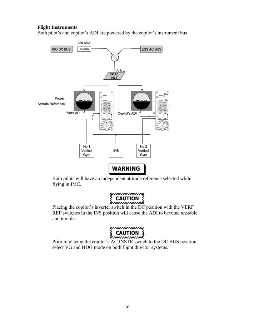
Flight Instruments
Both pilot’s and copilot’s ADI are powered by the copilot’s instrument bus
Both pilots will have an independent attitude reference selected while
flying in IMC.
Placing the copilot’s inverter switch in the DC position with the VERF
REF switches in the INS position will cause the ADI to become unstable
and tumble.
Prior to placing the copilot’s AC INSTR switch to the DC BUS position,
select VG and HDG mode on both flight director systems.
17
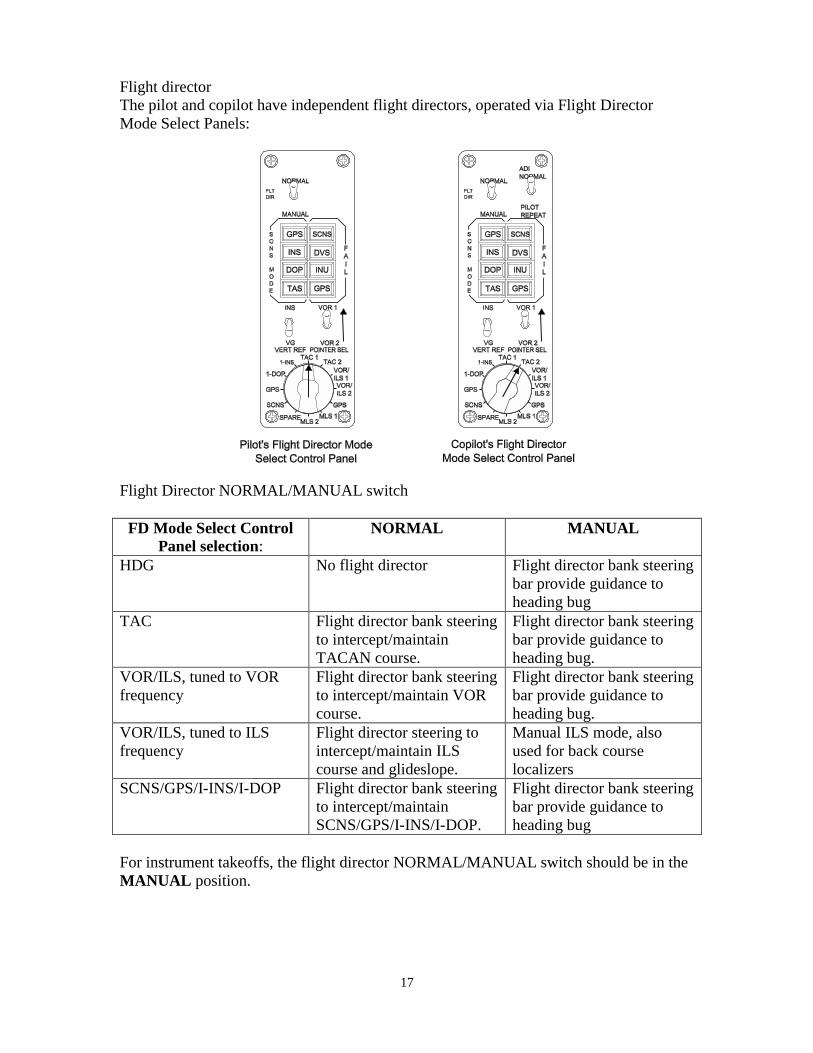
Flight director
The pilot and copilot have independent flight directors, operated via Flight Director
Mode Select Panels:
Flight Director NORMAL/MANUAL switch
FD Mode Select Control
Panel selection: NORMAL MANUAL
HDG No flight director Flight director bank steering
bar provide guidance to
heading bug
TAC Flight director bank steering
to intercept/maintain
TACAN course.
Flight director bank steering
bar provide guidance to
heading bug.
VOR/ILS, tuned to VOR
frequency
Flight director bank steering
to intercept/maintain VOR
course.
Flight director bank steering
bar provide guidance to
heading bug.
VOR/ILS, tuned to ILS
frequency
Flight director steering to
intercept/maintain ILS
course and glideslope.
Manual ILS mode, also
used for back course
localizers
SCNS/GPS/I-INS/I-DOP Flight director bank steering
to intercept/maintain
SCNS/GPS/I-INS/I-DOP.
Flight director bank steering
bar provide guidance to
heading bug
For instrument takeoffs, the flight director NORMAL/MANUAL switch should be in the
MANUAL position.

18
The pilot navigation selector has priority, preventing the copilot from selecting the same
radio navaid. If the copilot selects the same radio as selected by the pilot, the amber
“SELECTED NAV SYSTEM OFF” under the HSI will illuminate, and the copilot will be
disconnected from any navigation information:
The SELECTED NAV SYSTEM OFF does not apply if both the pilot and copilot
simultaneously select:
HDG
SCNS
I-1NS
I-DOP
The copilot has an ADI selector switch (NORMAL, PILOT REPEAT). When the ADI
selector switch is placed in the PILOT REPEAT position during an ILS approach, the
copilot’s ADI repeats the ILS information from the pilot’s ADI. The green COPILOT
ADI REPEAT light will illuminate under the copilot’s HSI, provided the pilot has
selected VOR/ILS-1 or VOR/ILS-2 with the MODE SEL switch and an ILS frequency
has been selected.
Air data instruments
The H-model has a significant position error correction. There is a 5-10 knot
airspeed difference (average 8 knot) between H-model aircraft and C-130s
equipped with the Rosemount system. The Rosemount system indicated
HIGHER airspeeds.
H-Model Drum/Pointer Airspeed Indicator

19
Fuel
The fuel indicators are analog and there is no direct indication when they are powered.
The fuel indicators are powered from the AC INST & ENGINE FUEL CONTROL bus.
As a technique, to ensure the AC INST & ENGINE FUEL CONTROL is powered before
reading the fuel quantity, ensure the TIT gage OFF flags are removed from view.
If analog gages are installed, before using the totalizer, add up the individual tank
quantities and ensure the totalizer is accurate
The fuel dumping system in the H2 consist of a dump manifold without dump valves, so
that any dump pump operation will dump fuel overboard without requiring a second
switch action. This makes the dump pumps unusable for tank-to-tank fuel trimming.
H2 Fuel panel, aircraft prior to 84-0206
H2 Fuel Panel, aircraft 84-0206 and later
If any fuel quantity indicator is off scale high, off scale low, fluctuates
erratically, or is inoperative, pull the associated fuel quantity indicator
circuit breaker. The circuit breaker will not be reset until proper inspection
and repairs have been made.

20
Hydraulics
Navigation
The aircraft has two identical C-12 compasses. The No 1 C-12 compass is associated
with the pilot; the No 2 C-12 compass is associated with the copilot. The C-12 compasses
are normally operated in the magnetic-slaved mode (mode switch in MAG). When
operating correctly, the annunciator pointer should be approximately centered. Erratic
movement or oscillation of the heading pointer indicates a malfunction, and the compass

21
shouldn’t be relied upon. The two compasses should indicate within 2º when free of other
aircraft and ground equipment, or in flight in straight and level flight.
Note: VOR 1 / 2 pointer selection is made via the POINTER SEL switch on the Flight
Director Mode Select Panel.

22
Autopilot
The H2 is equipped with the AN/AYW-1 Automatic Flight Control System (AFCS,
sometimes called the All Weather Flight Control System (AWFCS)).
There are two autopilot flight control systems (AFCS), labeled AP1 and AP2. AP1 is
associated with the pilot and uses the INS for an attitude reference, AP2 with the copilot
and uses the pilot’s VG for an attitude reference. The autopilot can be engaged by
pressing the AP1 or AP2 push button on the flight control panel, located on the pedestal
behind the throttle quadrant. The following conditions must be met to engage the
autopilot:
Turn ring – centered
Elevator trim – NORM
PITCH and LAT switches – ON
No 1 compass system must be operable to engage AP1
No 2 compass system must be operable to engage AP2
Flight Control Panel

23
Autopilot modes are indicated on the glare shield mounted flight progress-warning panel
(FPWP). The lights on the FPWP can only be checked by running an autopilot BIT:
Flight Progress – Warning Panel
The only way to check the FPWP lights is to run the autopilot BIT on the ground.
Autopilot engagement is indicated by illumination of the green annunciator bar above the
push button and on the flight progress-warning panel.
The autopilot engages in basic modes:
Roll: heading hold (wings level) or roll attitude hold (if coupled in a bank)
Pitch: pitch attitude hold
The autopilot will disengage when the copilot’s instrument power switch is
placed to the DC or OFF position.

24
The autopilot will respond to pitch and roll inputs made via the integrated pitch and roll
controller (pitch wheel and turn knob).
During high speed operation, the airplane responds quickly to large
movements of the pitch wheel (up to ± 30°of pitch) that could result in injury
or structural damage.
The pitch and lateral axis of the autopilot may be independently disconnected using the
LAT and PITCH switches on the Flight Control Panel
Altitude hold may be engaged by pressing the ALT HOLD button on the Flight Control
Panel. The autopilot will maintain the altitude at the time the button was pressed. If
speed-on-pitch mode was active, selecting ALT HOLD will disengage speed-on-pitch
mode (described below).
Mode Control Panel

25
FLT DIR: Couples the autopilot to the onside (AP1 engagedPilot, AP2 Copilot)
flight director. The flight director steering bars must be displayed in the ADI for the
autopilot to couple. The autopilot will couple to both the lateral or pitch axis of the flight
director, if present. If either PITCH or LAT off is selected, the other axis will remain
engaged.
When flying an approach with FLT DIR selected, the autopilot may not
correct for a deviation from the glideslope, which may result in remaining
above or below the glideslope. If the airplane remains off glideslope,
disengage the autopilot and complete the approach manually.
SPEED ON PITCH
The speed-on-pitch hold mode may be engaged by pressing the SPEED-ON-PITCH
button Mode Select Panel. The autopilot will maintain the indicated airspeed at the time
the button was pressed, and is designed for climbs and descents. In the speed on pitch
mode, the autopilot system uses the elevator to maintain a target indicated airspeed.
While in speed on pitch mode, the pilot is responsible for establishing the desired vertical
rate with the throttles; climb power for climbs and flight idle for descents. If altitude hold
was active, selecting SPEED-ON-PITCH will disengage ALT HOLD.
Speed on pitch mode should not be engaged during flight in greater than light
turbulence. If speed on pitch is engaged in turbulence, the autopilot will
aggressively change pitch attitude, attempting to follow airspeed fluctuations.
This may result in personnel and/or objects being tossed about in the cabin.

26
HEADING
When the HDG mode is engaged, the aircraft will turn in the shortest direction to the
onside (AP1Pilot, AP2 Copilot) HSI heading bug. To avoid an unanticipated turn,
the heading bug should be on the desired heading before engaging:
If the heading bug is moved through 180 degrees, the autopilot will reverse the direction
of the turn.

27
LNAV-LOC
Pressing the LNAV-LOC button arms the autopilot to capture and track the onside
(AP1Pilot, AP2 Copilot) lateral guidance (LOC, SNCS, TAC, VOR)

28
APPR (Approach)
Pressing the APPR button arms the autopilot to capture and track the onside (AP1Pilot,
AP2 Copilot) localizer and glide slope. The heading mode may be engaged prior to
APPR, which allows the heading bug to be used to follow vectors until the localizer is
captured.
The autopilot may capture glideslope before capturing the localizer. If this
occurs, the autopilot will fly the glideslope, which may result in a descent
prior to the cleared zone.
Placing the ADI selector switch to the SKE position while the autopilot is
engaged in the APPR mode will cause the autopilot to disconnect.
When the LATERAL axis of the autopilot is engaged, the autopilot makes parallel inputs
for turn coordination and yaw damping. Parallel means the autopilot rudder inputs are in
parallel with the pilot's inputs, so if the pilot makes a rudder input that the autopilot is not
commanding, the autopilot will attempt to counter the pilot input. This is different than
other autopilots such as the KC-135 or B737-B777 where the autopilot yaw damping/turn
coordination are made in series with the pilot inputs, allowing the pilot to make rudder
trim changes without fighting the autopilot.

29
If the pilot attempts to put in rudder trim with the LATERAL axis engaged, the autopilot
will end up putting in an additional correction. So in order to trim the aircraft for an
engine out situation, either disconnect the autopilot or disengage the LATERAL axis.
Input rudder trim as required, then reconnect the autopilot/reengage the LATERAL axis.
The rudder trim will then be correct for a single airspeed/power setting combination. If
the aircraft is maneuvered away from the trimmed condition, the autopilot will fly the
aircraft in side slip. It is possible and acceptable to trim the aircraft with an intermediate
amount of rudder trim, then fly an engine-out approach with the autopilot engaged. The
pilot should be aware that the aircraft will be in side slip as the airspeed and power are
changed from the trim condition.
Autopilot disconnect
The autopilot may be disconnected by:
Pressing the autopilot release on either control wheel
Pressing the AP1 button, with AP1 engaged
Pressing the AP2 button, with AP2 engaged
Positioning the elevator tab power selector to OFF or EMER
Using the elevator trim
Placing both LAT and PITCH switches OFF
The normal means of disconnecting the autopilot is to use the autopilot release switch.
The AUTO PILOT DISC warning will flash, and can be extinguished by pressing the
release switch a second time:
Autopilot failures:
Trim command failure AP1 engaged and INS
attitude reference bad
AP2 engaged and pilot’s
attitude gyro bad
Radar The early C-130H models are equipped with the APN-59 ground mapping radar. Later
and modified aircraft are equipped with the digitial APN-241 radar.
The APN-59 is a real beam only, with a raw video plan position indicator (PPI). Radar
controls are located at the navigator’s station, with a removable repeater scope for the
pilots. The pilot’s repeater scope is washed out in sunlight. This, coupled with the
controls being at the navigator’s station, means that the radar is not operable by the pilots.
The radar hazard area to personnel extends 40 feet from the nose of the aircraft, while the
explosives/fuel ignition hazard area extends 300 feet from the nose of the aircraft. Get
clearance from the pilots prior to operating the radar.

30
Brakes:
The C-130H aircraft prior to 85-0035 are equipped with 2030 psi brakes. C-130H aircraft
85-0035 and up are equipped with 3,000 psi brakes.
Communications
Most C-130H model aircraft are equipped with 2 UHF radios and 1 VHF radio. The
radios are normally controlled through the SCNS control head, although UHF #1 may be
controlled through the manual control head by turning it on.

31
Normal Procedures
Engine Start
Condition Stop Start Criteria
Within 5 seconds of start
switch actuation START VALVE OPEN light does not illuminate
No rotation
35% RPM No Fuel Flow
No Ignition
No Engine or Gearbox oil pressure indication
Peak TIT < 720 Low TIT
Peak TIT > 850 Hot start
60 seconds On speed (70 seconds in high temperatures)
Hydraulic Pressure indication
On Speed + 30 seconds Full hydraulic pump pressure
Temperature limits
Condition Action Required
< 720ºC Maintenance action required prior to flight. Record in 781.
720-749ºC Continue and perform temperature controlling check prior
to flight. Record starting and crossover TIT. If TIT
malfunction exists, place condition lever to GND STOP
750-830ºC Normal
831-850ºC Leave running. Record peak TIT in 781 and continue
mission
851-965ºC Discontinue the start, record in 781. One restart is permitted
after cooling below 200ºC TIT. If TIT exceeds 850ºC on 2nd
start, discontinue and record. Restart not recommended
>965ºC Discontinue and record peak TIT in 781. Over temperature
inspection required.

32
Engine Starter limits:
1 minute ON
1 minute OFF
1 minute ON
5 minute OFF
1 minute ON
30 minute OFF
NOTE The APU generator must be on for low speed ground idle operation. If the
APU generator fails, the low speed ground idle buttons must be manually
disengaged to prevent a drain on the aircraft battery.
Taxi
Managing oil temperatures.
Without oil cooler augmentation, the oil temperature must be closely monitored during
taxi. Optimum cooling occurs when the engine is operated at LSGI, with the throttle
advanced 1 to 1-1/2 knob widths above the ground idle detent. Conditions permitting,
attempt to taxi will all four engines in LSGI. Some engineers use the technique of
closing the oil cooler flaps slightly, with the belief this causes an air burble that aids
cooling. Use of reverse thrust will quickly overheat the oil.
Descent
During descent below 15,000 feet MSL, manually open the oil cooler flaps and place the
switches to the FIXED position. Monitor oil temperature and manually control the oil
cooler flaps to keep the oil temperature close to 60ºC.
Engine Shutdown

33
Emergency Procedures
APU Emergency Shutdown (Ground/In flight)
1. Fire Handle - “Pulled” (E)
2. Agent – “Discharged” (for fire) (E)
Bleed Air Leak
If an engine bleed air regulator cannot be closed (valve closure is determined by
observing torque increase on the affected engine) and the bleed air system is
leaking, it may be necessary to shut down the engine.
Do not operate the APU Bleed air after landing with a bleed air leak. If the
uncontrolled loss of bleed air cannot be isolated, operation of the APU bleed air
may repressurize the area(s) where the failure occurred.
David Fedors/25 March 11/5-7037