by robert steven horvath graduate school-new …
TRANSCRIPT

SYNTHESIS AND PROCESSING OF NANOSTRUCTURED BN AND BN/Ti COMPOSITES
by
ROBERT STEVEN HORVATH
A Dissertation submitted to the
Graduate School-New Brunswick
Rutgers, The State University of New Jersey
in partial fulfillment of the requirements
for the degree of
Doctor of Philosophy
Graduate Program in Material Science and Engineering
written under the direction of
Dr. Bernard H. Kear
and approved by
_______________________
_______________________
_______________________
_______________________
New Brunswick, New Jersey
JANUARY 2015

ii
ABSTRACT OF THE DISSERTATION
Synthesis and Processing of Nanostructured BN and BN/Ti Composites
By ROBERT STEVEN HORVATH
Dissertation Director:
Dr. Bernard H. Kear
Superhard materials, such as cubic-BN, are widely used in machine tools, grinding
wheels, and abrasives. Low density combined with high hardness makes c-BN and its
composites attractive candidate materials for personnel and vehicular armor. However,
improvements in toughness, and ballistic-impact performance, are needed to meet
anticipated performance requirements. To achieve such improvements, we have targeted
for development nanostructured c-BN, and its composites with Ti. Current research utilizes
an experimental high pressure/high temperature (HPHT) method to produce these materials
on a laboratory scale. Results from this work should transfer well into the industrial arena,
utilizing high-tonnage presses used in the production of synthetic diamond and c-BN.
Progress has been made in: (1) HPHT synthesis of cBN powder using Mg as catalyst;
(2) HPHT consolidation of cBN powder to produce nanostructured cBN; (3) reactive-
HPHT consolidation of mixed cBN/Ti powder to produce nanostructured Ti- or TiB2/TiN-
bonded cBN; and (4) reactive-HPHT consolidation of mixed hBN/Ti powder to produce
nanostructured Ti-bonded TiB2/TiN or TiB2/TiN. Even so, much remains to be done to lay
a firm scientific foundation to enable the reproducible fabrication of large-area panels for
armor applications. To this end, Rutgers has formed a partnership with a major producer
of hard and superhard materials.

iii
The ability to produce hard and superhard nanostructured composites by reacting cBN
or hBN with Ti under high pressure also enables multi-layered structures to be developed.
Such structures may be designed to satisfy impedance-mismatch requirements for high
performance armor, and possibly provide a multi-hit capability. A demonstration has been
made of reactive-HPHT processing of multi-layered composites, consisting of alternating
layers of superhard Ti-bonded cBN and tough Ti. It is noteworthy that the pressure
requirements for processing Ti-bonded cBN, Ti-bonded TiB2/TiN, and their corresponding
multi-layered structures are in the 0.1-1.0 GPa range, well within the capabilities of today’s
hot-pressing technologies; thus scaling this new reactive-HPHT processing technology
seems assured.
Future research will focus on establishing mechanisms and kinetics of the various phase
transformations observed during reactive-HPHT processing, with the objective of being
able to optimize processing parameters to generate nanostructured cBN-based and
TiB2/TiN-based composites that display superior mechanical properties, particularly under
high-strain-rate conditions.

iv
Dedication
I would like to dedicate this thesis to the memory of three people very close to my
heart.
My late Mother Dianne Horvath whose 30+year career in education inspired me to be
something more than a professional, to devote my life to an occupation that has rewards
above and beyond monetary compensation. We miss you every day.
My Brother from another mother, the late Dr. Howard Fritz. Howie had been there,
so he knew how to talk about it, and then suddenly he was gone. God Bless you Howie.
My close personal friend the late Laura Giaquinto Ballesteros, whose heroic yet tragic
battle with cancer is an inspiration to us all. We love you Laura.

v
Acknowledgements
This research endeavor was made possible through the guidance, direction, and funding
provided by Dr. Bernard H. Kear, and Dr. Stephen D. Tse, graduate research advisers.
Significant contributions were also made by Dr. Oleg Voronov of Diamond Materials Inc.
with respect to sample preparation, processing and considerable technical insight. Also, I
would like to extend my gratitude to Dr. Thomas Tsakalakos for contributions to this
venture through his technical insight. Also, I would like to thank Dr. Jafar Al-Sharib for
TEM and technical contributions. The guidance and support provided by Dr. Richard
Lehman, Dr. Lisa Klein, and Dr. Rich Haber toward my graduate school and professional
ventures and their ability to find creative solutions to my unique situation has been greatly
appreciated.
I would like to acknowledge my family for their support patience, and
encouragement;
Andrew Horvath Charles M. Horvath
Christian Horvath Anne M. Horvath
Juliana Horvath Charles J. Horvath
Angelina Horvath
Most of all , I would like to thank my companion Ms. Janet Scherer, for her unwavering
love, support and motivation. Words can not express my gratitude, Thank you all.

vi
Table of Contents
Abstract ............................................................................................................................... ii
Dedication .......................................................................................................................... iv
Acknowledgements ............................................................................................................. v
Table of Contents ............................................................................................................... vi
List of Tables ................................................................................................................... viii
List of Figures .................................................................................................................... ix
A. Overview ..................................................................................................................... 1
B. Relevant Prior Research ................................................................................................. 7
C. Crystal Structures and Properties ................................................................................. 11
C.1 Boron nitride .......................................................................................................... 11
C.2 Titanium diboride ................................................................................................... 14
C.3 Titanium nitride ...................................................................................................... 18
D. Experimental Methods ................................................................................................. 20
D.1 Apparatus ............................................................................................................... 20
D.2 Calibration .............................................................................................................. 21
D.3 Procedure ............................................................................................................... 23
E. Characterization Techniques ........................................................................................ 24
E.1 X-ray diffraction ..................................................................................................... 24
E.2 Scanning electron microscopy ................................................................................ 27

vii
E.3 Transmission electron microscopy ......................................................................... 28
E.4 Density measurements ............................................................................................ 29
E.5 Hardness measurements ......................................................................................... 29
F. Results and Discussion ................................................................................................. 31
F.1 Synthesis of cBN powder ....................................................................................... 31
F.2 Consolidation of cBN powder ................................................................................ 34
Powder #1 ................................................................................................................. 34
Powder #2 ................................................................................................................. 35
F.3 Consolidation of mixed cBN/Ti powder................................................................. 40
Powder #1 + Ti ......................................................................................................... 42
Powder #2 + Ti ......................................................................................................... 48
F.4 Consolidation of mixed hBN/Ti powder ................................................................ 51
F.5 Consolidation of multi-layered structures .............................................................. 54
G. Discussion .................................................................................................................... 59
H. Future Work ................................................................................................................. 65
Appendix A ....................................................................................................................... 67
References ......................................................................................................................... 71

viii
List of Tables
Table 1 - Properties of selected hard and superhard materials ............................... 3
Table 2 - Cutting tool performance of diamond and cBN relative to WC/Co
cemented carbide ............................................................................................. 8
Table 3 - Pressure dependence of phase transitions in several materials at ambient
temperature. .................................................................................................... 22
Table 4 - Summary of results for powder #1, after consolidation at 0.3 and 8.0
GPa/1000ºC/15 min. ....................................................................................... 35
Table 5 - Summary of results for powder #2, after consolidation at 0.3 and 8.0
GPa/1000-1900ºC/5-15 min. ........................................................................... 36
Table 6 - Densities of cBN:Ti samples, after consolidation at 0.3, 2.0, and 8.0
GPa/1000ºC/15min. ........................................................................................ 42
Table 7 - XRD phase analysis of cBN:Ti samples, after consolidation at 0.3, 2.0,
and 8.0 GPa/1000ºC/0,3,&15min. .................................................................. 43
Table 8 - Densities of cBN:Ti samples, after consolidation at 0.3, 2.0, and 8.0
GPa/1000ºC/15,3,0 min. ................................................................................. 50
Table 9 - XRD phase analysis of cBN:Ti samples, after consolidation at 0.3, 2.0,
and 8.0 GPa/1000ºC/15min. ........................................................................... 51
Table 10 - Densities of hBN:Ti samples, after consolidation at 0.1, 0.3, 2.0, and
8.0 GPa/1000ºC, showing high density of fully reacted material. .................. 53
Table 11 - XRD phase analysis of hBN:Ti samples, after consolidation at 0.3, 2.0,
and 8.0GPa/1000ºC. ........................................................................................ 53

ix
List of Figures
Figure 1 - Schematic of early HPHT apparatus used by H.T. Hall ............................. 7
Figure 2 - Effect of nanoscale grain size on Vickers hardness of cBN ....................... 9
Figure 3 - Thermal stability of nano-cBN relative to nano-diamond ........................ 10
Figure 4 - Bundy-Wentorf’s phase diagram for BN .................................................. 11
Figure 5 - Equilibrium phase diagram for BN .......................................................... 12
Figure 6 - Hexagonal structure of boron nitride ........................................................ 12
Figure 7 - Wurtzite structure of boron nitride ........................................................... 13
Figure 8 - Cubic structure of boron nitride ................................................................ 13
Figure 9 - Hexagonal crystal structure of TiB2. ........................................................ 14
Figure 10 - Flexural strength of TiB2 as a function of grain size .............................. 15
Figure 11 - Elastic modulus of TiB2 as a function of density .................................... 16
Figure 12 - Fracture toughness of TiB2 as a function of grain size ........................... 17
Figure 13 - Hardness of TiB2 versus applied load ..................................................... 18
Figure 14 – Cubic crystal structure of (TiN) ............................................................. 19
Figure 15 - Schematic of HPHT apparatus ............................................................... 21
Figure 16 – Pressure-force calibration for HPHT apparatus ..................................... 22
Figure 17 - Temperature-power curve for calibration of HPHT apparatus ............... 23
Figure 18 - Typical HPHT processing cycle ............................................................. 23
Figure 19 - Example of a Williamson-Hall plot for crystallite size and strain
approximation from peak broadening at FWHM .................................................. 27
Figure 20 - XRD pattern of powder #1, indicating grain size ~56nm ....................... 32
Figure 21 - SEM micrographs of powder #1, showing 1-10 µm particle size. ......... 32

x
Figure 22 - XRD pattern of powder #2, showing narrow diffraction peaks, indicating
coarse grain/particle size. ...................................................................................... 33
Figure 23 - SEM micrograph of powder #2 50-100 µm particle size and cleavage
facets. .................................................................................................................... 33
Figure 24 - XRD spectra for powder #2, after processing at 8.0 GPa/1000-1900ºC/5-
15 min, showing peak broadening ........................................................................ 37
Figure 25 - SEM micrographs of fracture surfaces of c-BN samples, after
consolidation at: (a) 1000ºC, (b) 1300ºC, (c) 1600ºC, and (d) 1900ºC, all at 8 GPa.
............................................................................................................................... 38
Figure 26 - TEM micrographs of a c-BN sample, after consolidation at 8 GPa/
1300ºC/15 min, showing (a) nanocrystalline structure, and (b) evidence for grain
texturing. ............................................................................................................... 39
Figure 27 - TEM micrographs of twinning in a c-BN sample, after consolidation at 8
GPa/ 1300ºC/15 min: (a) single twin ~10 nm in width, and (b) multiple twins ~20
nm in width. .......................................................................................................... 40
Figure 28 - XRD spectra for cBN, hBN, Ti, TiN, TiB2, and TiC from ICSD files ... 41
Figure 29 - SEM image of 50:50 cBN/Ti, after consolidation at 8.0 GPa/1000ºC/15
min ........................................................................................................................ 44
Figure 30 - XRD spectra for 50:50 cBN:Ti, after consolidation at 0.3, 2.0 and 8.0
GPa/1000ºC/15 min. ............................................................................................. 46
Figure 31 - XRD spectra for 70:30 cBN:Ti, after consolidation at 2.0 GPa/1000ºC/15
min, showing evidence for intermediate-phase formation (arrows) ..................... 48

xi
Figure 32 - SEM images of 30:70 hBN:Ti after consolidation at 0.3 GPa/1000oC: (a)
15 min and (b) 120 min, showing smaller fraction of hBN particles (dark contrast)
with longer holding time. ................................................................................... 52
Figure 33 - EDS map of 30:70 hBN:Ti sample, after processing at 0.3
GPa/1000ºC/15min, showing presence of B and N in the Ti-rich matrix phase. 54
Figure 34 - Schematic of a bi-layered composite sample, showing thickness of each
layer and its composition. ..................................................................................... 56
Figure 35 - XRD spectra of a bi-layered composite sample, showing (a) TiC in its top
layer, and (b) cBN/TiC in its bottom layer. .......................................................... 57
Figure A.1 - Example of the pitted surface of a consolidated sample of powder#1,
showing extensive grain pullout due to polishing. Also shown is a Vickers hardness
indent (arrow)........................................................................................................ 67
Figure A.2 - Nanoindentation data for a nano-cBN sample, after HPHT consolidation
of powder #1 at 8.0 GPa/1000ºC/15min ............................................................... 69

1
A. Overview
Cubic-boron nitride (cBN) is widely used in machine tools, drill bits, and grinding
wheels [1-4]. Recently, interest has developed in its potential for lightweight personnel and
vehicular armor. Currently, the preferred materials are B4C and SiC. Because of its much
higher hardness and stiffness, cBN is an attractive alternative for next generation armor.
However, to ensure superior ballistics performance, its fracture toughness needs to be
improved, without seriously compromising hardness and strength.
To realize such properties, we have been investigating high pressure/high temperature
(HPHT) methods to produce: (1) nanostructured cBN, since it is known that hardness and
toughness increase with decreasing grain size; and (2) nanostructured Ti-bonded cBN,
where the presence of the metal-binder phase imparts toughness, as in Co-bonded WC.
Progress has been made in both areas, but the discovery of a new processing route to
produce BN/Ti-base nanocomposites under reduced-pressure conditions is perhaps most
significant, since it enables HPHT powder-processing technology to be scaled. Thus, there
is the prospect of being able to fabricate large-area superhard armor panels in a cost-
effective manner. However, much remains to be done to optimize processing parameters
to make this a commercially-viable technology. Presently, a 300-ton force press, located at
Diamond Materials Inc. (DMI), is used to make small disc-shaped pieces (typically 4-mm
dia. x 3 mm) for characterization and testing purposes. Looking ahead, the goal is to
fabricate a 1-meter square demonstration armor panel, which will be achieved using a
10,000-ton force press at Diamond Innovations - a leading company in the hard and
superhard materials industry.

2
As will be shown, under varying HPHT processing conditions, Ti can either bond
directly to cBN to form a superhard Ti-bonded cBN composite or react with cBN to form
a superhard TiB2/TiN-bonded cBN composite. In the latter case, it is significant that the
reaction occurs at reduced pressures, thus enabling scaling of the technology. Similar
pressure-controlled reactions occur between hBN and Ti. In particular, a fully dense hard
Ti-bonded TiB2/TiN composite is produced via control of an exothermic reaction that
accompanies the powder-consolidation process, here described as reactive-HPHT (r-
HPHT) consolidation. A significant advantage of using hBN powder as starting material is
its low cost relative to cBN powder. Similar reactions are anticipated between mixed BN
and Al and/or Mg powders under r-HPHT processing conditions.
The ability to produce hard and superhard composites by reacting cBN or hBN with Ti
under high pressure also enables multi-layered structures to be developed. In principle,
such structures may be designed to satisfy impedance-mismatch requirements for high
performance armor, and possibly provide a multi-hit capability. A demonstration has been
made of r-HPHT processing of a multi-layered composite that consists of alternating layers
of superhard Ti-bonded cBN and tough Ti. Compositional grading of the interphase
interfaces occurs quite naturally during processing, which ensures good bonding between
the dissimilar materials[5]. It is noteworthy that the pressure requirements for processing
Ti-bonded cBN, Ti-bonded TiB2/TiN, and their corresponding multi-layered structures, are
as low as 0.1-0.3 GPa, which are well within the capabilities of today’s hot-pressing
technologies; thus scaling this new r-HPHT technology seems assured.
In this research project, progress has been made in: (1) HPHT synthesis of cBN powder
using Mg as catalyst; (2) HPHT consolidation of cBN powder to form nanostructured cBN;

3
(3) r-HPHT consolidation of mixed cBN/Ti powder to produce nanostructured Ti- or
TiB2/TiN-bonded cBN composites; (4) r-HPHT consolidation of mixed hBN/Ti powder to
produce nanostructured Ti-bonded TiB2/TiN or TiB2/TiN composites; and (5) r-HPHT
fabrication of a demonstration multi-layered structure, comprising alternating layers of
superhard Ti-bonded cBN, hard TiB2/TiN, and tough Ti. As noted above, such a layered
composite offers considerable flexibility in the design of armor to satisfy specific ballistics
requirements.
Table 1 presents published data on the grain-size dependence of hardness and
toughness of cBN. It is noteworthy that reducing the grain size of cBN from micro- to
nano-scale dimensions increases both hardness and toughness. The increase in hardness is
ascribed to the well known Hall-Petch effect[6], whereas the increase in toughness is
ascribed to the difficulty of propagating a crack through a nano-grained material. In
general, the crack follows a tortuous path along the weaker grain boundaries rather than
through the nano-grains themselves via cleavage fracture. A similar mechanism explains
the high hardness and toughness of nano-twinned cBN.
Table 1 - Properties of selected hard and superhard materials
[7-16]
Even though nanocrystalline c-BN displays higher hardness and toughness than its
microcrystalline counterpart, it seems unlikely that the toughness will be sufficient to avoid

4
coarse-scale fracturing during ballistic impact, accompanied by little energy absorption.
On the other hand, a Ti-bonded c-BN composite, comprising a high fraction of superhard
c-BN particles uniformly dispersed in a much tougher Ti binder phase should experience
fine-scale fracturing, and therefore greater energy absorption. For example, a 70:30 c-
BN:Ti composite should exhibit superior hardness and modest toughness, whereas a 30:70
c-BN:Ti composite should exhibit modest hardness and superior toughness. Moreover, a
multi-layered structure, comprising alternating superhard, hard, and ductile layers should
provide even greater energy absorption, and further enhance ballistics performance.
However, much remains to be done to optimize processing parameters to realize superior
performance for multi-layered composites with compositionally-graded interfaces.
Looking ahead, it is anticipated that the mechanical performance of a multi-layered
structure, comprising alternating layers of superhard Ti-bonded cBN, hard Ti-bonded
TiB2/TiN, and tough Ti (or its alloys), can be designed to meet the performance
requirements of most personnel and vehicular armor applications[17].
These considerations provided the primary motivation for the present research on
synthesis and processing of nanostructured BN and BN/Ti composites for lightweight
armor. As will be shown, a successful demonstration of HPHT consolidation of cBN
powder to form nanocrystalline-cBN has been made, but only at very high pressures, 5.0-
8.0 GPa. Such processing conditions are accessible using today’s industrial-scale HPHT
presses [18], but scaling to 5-cm diameter is about the practical size limit [19]. To
overcome this scaling limitation, on-going research is investigating methods to reduce the
pressure requirements into the scalable range, preferably <2.0 GPa. A promising approach

5
is to use plasma-synthesized nanopowder as a sintering aid to consolidate powder compacts
of micron-size cBN powder.
Concurrently, research continues on r-HPHT processing of Ti-bonded cBN and Ti-
bonded TiB2/TiN composites, inspired by the discovery made herein that nanostructured
hard and superhard BN/Ti composites can be produced at pressures as low as 0.1-0.3 GPa,
which places no practical limits on scaling the process using today’s hot-pressing
equipment. Moreover, the introduction of controlled distributions and volume fractions of
Ti as binder phase should provide needed fracture toughness. In the case of a multi-layered
structure, comprising alternating layers of superhard Ti-bonded cBN, hard Ti-bonded
TiB2/TiN, and tough Ti, another singular benefit is the flexibility afforded in armor design
and fabrication. For example, only the outer layer facing an incoming projectile needs to
be made of superhard Ti-bonded cBN; underlying or backing layers may be made of less
costly hard/tough Ti-bonded TiB2/TiN and tough Ti or its alloys. So far, a first
demonstration has been made of the ability to fabricate such a layered composite, with the
ability to control structure at nano-scale dimensions. Much remains to be done to produce
an end-product, say in the form of a large-area armor panel that satisfies the stringent
requirements with respect to ballistics performance, but it now seems achievable.
Superhard machine tools, in various sizes and shapes are widely employed in
manufacturing. An important market niche is held by cBN, since it is much better than
diamond in resisting degradation in high-speed machining, where the tool/workpiece
interface gets very hot. If this problem is severe enough, as in machining of many hardened
steels and nickel-base superalloys, then cBN tools are preferred, since diamond tools
rapidly wear out by reaction with the workpiece itself and/or by oxidation [12]. Hence,

6
another important outcome of this research is a new class of nanostructured
superhard/tough cBN tools that resist degradation at high machining speeds, even when the
tool/workpiece interface gets white hot! An immediate impact in high-speed machining of
nickel-base superalloys is expected, since there the need is greatest and potential pay-off
significant.

7
B. Relevant Prior Research
Pioneering research, conducted by H.T. Hall[3], has shown that the transformation of
hBN to cBN occurs at 5.0-9.0 GPa/1500-2000oC in the presence of Mg, apparently acting
as a catalyst or activator. The fully consolidated cBN has high hardness, easily scratches
B4C, and is insoluble in most acids. Wentorf [4] also reported that Li and Al are also
effective catalysts, but, unlike diamond, Fe, Ni and Mn are not. In the absence of a catalyst,
Bundy and Wentorf [2] found that the conversion of hBN to cBN occurs at a minimum
pressure of 11.5 GPa at 1730oC.
Figure 1 - Schematic of early HPHT apparatus used by H.T. Hall[3]
When processing is conducted at the highest temperature and pressure close to the
hexagonal-to-cubic phase equilibrium line crystallite size is large, apparently due to the
increased thermodynamic driving force, but crystallite quality is poor. Surfaces of large
tetrahedral- and octahedral-shaped cBN crystallites formed at high rates show growth steps
and ledges, and at the highest rates twinning is observed [3]. The color of the cBN particles,
which varies from white to black, is attributed to differences in the material’s
stoichiometry. Since the discovery of cBN, various superhard materials have been
developed to fill the gap in hardness between cBN and diamond. For example, metastable

8
forms of superhard BC2N and has been reported [20], as well as B6O and B13N2 phases. All
these compounds have structures similar to diamond and cBN.
Hibbs and Wentorf [2] were first to develop applications for monolithic or bulk
diamond and cBN. For machine tools and drill bits requiring good fracture toughness, thin
layers of superhard materials are bonded to supporting strong/stiff WC/Co substrates.
Processing parameters are 5.0-7.0 GPa at 1500-2000ºC, and grain sizes are 2.0-100 µm.
Table 2 shows, for several applications, superior machining performance of such Compax
tools relative to conventional WC/Co cemented-carbide tools.
Table 2 - Cutting tool performance of diamond and cBN relative to WC/Co
cemented carbide [2]

9
In a recent publication [12], Solozhenko et al. report the successful processing of bulk
nanocrystalline cBN (grain size 10-30 nm) via the direct (non-catalytic) transformation of
hBN at 20 GPa/1500ºC. Vickers hardness of the resulting cBN is 85 GPa, inset in Figure
2, and its grain size is 10-30 nm. When the processing temperature is raised to increase the
grain size to 300-400 nm, the hardness is reduced to 50 GPa, Figure 2, this value is typical
of today’s commercial micro-grained cBN. This trend is in accord with the Hall-Petch
relationship, indicating that plastic deformation (slip and/or twinning) is severely restricted
in an ultra-fine nanocrystalline structure[21]. The fracture toughness of nano-cBN is K1C =
10.5 MPa m1/2, higher than values, K1C = 2.8-6.8 MPa m1/2, for all known superhard BCN-
type phases. Thus, nano-cBN is harder and tougher than micro-cBN, and all related
superhard phases [12].
Figure 2 - Effect of nanoscale grain size on Vickers hardness of cBN[12]

10
Nano-cBN also displays thermal and chemical stability superior to diamond. For
example, thermo-gravimetric analysis shows that nano-cBN is more resistant to oxidation
than nano-diamond, Figure 3. The onset temperature for oxidation is 1460ºK for nano- and
micro-cBN, which compares with 950ºK for nano-diamond. This difference in behavior is
due to the formation of a relatively stable surface-passivation film of B2O3 on cBN,
whereas diamond reacts with ambient air to form CO2; in other words the diamond surface
experiences gasification. Under high vacuum conditions or in an inert atmosphere diamond
is stable up to about 1500ºK., then phase decomposition yields graphitic material.
Figure 3 - Thermal stability of nano-cBN relative to nano-diamond[12]

11
C. Crystal Structures and Properties
C.1 Boron nitride
At ambient pressure hBN is the stable phase, but at higher pressures and temperatures
hexagonal BN transforms to cBN, Figure 4. The latter, once formed, can be retained at
ambient pressure in a metastable state. However, to retain cBN after HPHT processing,
fast cooling and reduction in pressure is necessary; otherwise it reverts back to hBN. In
practice, an activator or catalyst is used to promote the transformation of hBN into cBN.
Subsequent experimental and theoretical work led to the now generally accepted phase
diagram shown in Figure 5[23].
Figure 4 - Bundy-Wentorf’s phase diagram for BN [23]
1, Bundy-Wentorf's diagram; 2, Equilibrium diagram; 3, h-BN <=> c-BN
boundary line (Solozhenko, 1994).

12
Figure 5 - Equilibrium phase diagram for BN[23]
1 is hexagonal-zinc blende (cubic)-liquid triple point; 2 metastable hexagonal-
wurtzite-liquid triple point; a) line of wurtzite metastable equilibrium; b) line
of metastable hexagonal melting; c) line of metastable wurtzite melting.
(Solozhenko et al. 1998)
The hexagonal structure of BN (hBN), Figure 6, has a ring-like arrangement of covalently-
bonded boron and nitrogen atoms within one atomic layer, with each such layer bonded to
adjacent layers by weak Van der Waals bonds.
Figure 6 - Hexagonal structure of boron nitride [24]

13
The wurtzite structure of BN (wBN), Figure 7, is an example of a hexagonal structure that
is common to many binary compounds, including other hard phases, such as α-SiC, GaN,
and AlN[25].
Figure 7 - Wurtzite structure of boron nitride[26]
The cubic structure of BN (cBN), Figure 8, comprises two interpenetrating face-centered
cubic lattices. Each atom in one lattice is covalently bonded to four nearest neighbor atoms
of the opposite type in the other lattice. The cBN structure is common in binary compounds,
and is often referred to as the zinc blende structure.
Figure 8 - Cubic structure of boron nitride [27]

14
C.2 Titanium diboride
The hexagonal structure of titanium diboride (TiB2), Figure 9, consists of planar stacking
of strong covalently-bonded Ti and B atoms; as such, it has an exceptionally high melting
point, 3215oC. It also has high hardness and stiffness, Table 1, but applications are limited
by the high temperature required for powder consolidation. If not properly controlled,
anisotropy in thermal expansion misfit between a and c axis of the hexagonal structure can
cause catastrophic failure during cool-down after sintering, at least for large-grained
material. Fully dense fine-grained TiB2, however, has been produced by hot pressing, hot
isostatic pressing, microwave sintering, and dynamic compaction[28], but applications are
still limited to a few commercial products: impact-resistant armor, heat-resistant crucibles,
and wear-resistant coatings.
Figure 9 - Hexagonal crystal structure of TiB2 [29].

15
Flexural strength of TiB2 increases with decreasing grain size, Figure 10, in accord with
the Hall-Petch relationship, but there is no data available for sub-micron or nano-grained
material. Data for elastic modulus, Figure 11, illustrates its sensitivity to the relative
density of the sintered product. For a high density, relatively pore-free product the modulus
is ~550 GPa; upper limit shown in Table 1.
Figure 10 - Flexural strength of TiB2 as a function of grain size [14]

16
Figure 11 - Elastic modulus of TiB2 as a function of density [14]
Reported values for fracture toughness of TiB2, Figure 12, indicate variability due to
variations in grain size, measurement method, and chemical purity. Relatively small
percentages of second phases are often present in sintered TiB2, resulting from raw
materials purity or intentionally added sintering aids to mitigate the effects of shrinkage
anisotropy. Fracture toughness is optimal at 98% pure TiB2, with density 4.5 g/cm3 and
grain size 5-10 µm, and has a value K1C = 6.2 MPa•m1/2. Interestingly, this toughness value,
unlike that for elastic modulus and flexural strength, is not inversely proportional to grain
size, but optimal at a median grain size value.

17
Figure 12 - Fracture toughness of TiB2 as a function of grain size[14]
Measurements of Vickers hardness of TiB2 do not show a strong dependence on grain size.
However, there is a considerable level of variability in the reported data that is attributed
to variations in the applied load, Figure 13. In order to more completely define the true
relationship between grain size and hardness for TiB2, much more work needs to be done,
which is beyond the scope of the present research.

18
Figure 13 - Hardness of TiB2 versus applied load[14]
C.3 Titanium nitride
The cubic structure of titanium nitride (TiN), with coordination identical to NaCl, is
depicted in Figure 14. It has a strong covalently-bonded structure, which is reflected in its
exceptionally high melting point, 3290ºC. Its density, calculated from lattice parameters
and assuming zero porosity, is 5.495 g/cm3. At a relative density of 96% the reported value
of elastic modulus is 450 GPa [7]. TiN also displays exceptional wear and corrosion
resistance, and hence is widely used in industrial coatings, but there is little demand for
bulk materials[30].
In a recent studies of bulk TiN [31], prepared by hot pressing at 1723-2023oK for 60-
1500 sec, reliable measurements of mechanical properties have been obtained. Vickers
hardness, after polishing under an applied load of 0.98 N is Hv = 24 GPa, whereas fracture

19
toughness after processing at 2023oK/16.6 MPa is K1C = 4.28 MPa •m1/2. Based on these
experiments, it now seems possible to produce bulk TiN structures with reproducible and
attractive properties.
Figure 14 – Cubic crystal structure of (TiN)[32]

20
D. Experimental Methods
In what follows, a description is given of the high pressure/high temperature (HPHT)
apparatus used throughout this research to synthesize nanostructured BN and BN/Ti
composites. A detailed description of the HPHT apparatus is presented, as well as methods
used for its calibration[33].
D.1 Apparatus
All HPHT experiments were performed at Diamond Materials Inc. (DMI) - a spinoff
company from Rutgers’ Center for Nanomaterials Research (Rutgers’ CNR). DMI’s
apparatus provides a highly flexible experimental platform, allowing systematic studies of
the influence of critical processing parameters - pressure, temperature and holding time -
on the resulting structures, phases, and properties of the consolidated materials. Experience
has demonstrated that this system yields reproducible results over a wide range of
processing parameters, 1-10 GPa/20-2000ºC.
Figure 15 shows a schematic of DMI’s HPHT apparatus, as described in considerable
detail in U.S. Patent 8,021,639 B [34]. Briefly, it consists of a matching pair of WC/Co
anvils and inserts, which are reinforced with pre-stressed steel rings. The arrangement
enables pressures to be applied that are higher than the compressive strength of the anvil
material. The reaction cell consists of a resistively-heated graphite crucible and insulating
ceramic spacers. A critical component is the pressure-transmitting medium, which consists
of deformable ceramic that is machined to match the profiles of the anvils. Under high
pressure, the plastically deformed ceramic exerts a strong restraining force on the reaction

21
cell, thus generating a high pressure in its working volume [35]. This is used routinely to
synthesize high pressure phases and to consolidate powders.
Figure 15 - Schematic of HPHT apparatus[36]
D.2 Calibration
Pressure is calibrated at ambient temperature for several known phase transitions in solid
materials, Table 3. Variation in the electrical resistivity as a function of pressure signals
that a phase transition has taken place. The dependence between loading force and
resistivity allow for precise calibrations to be made [35]. Temperature is calibrated via
known values of melting temperatures of different substances under high pressure. Under
ideal conditions, a sharp increase in electrical resistance of the reaction cell signals that
melting has occurred. In practice, the voltage drop across the reaction cell gradually
increases as melting occurs, and changes in current are measured [36][37].

22
Table 3 - Pressure dependence of phase transitions in several materials at
ambient temperature.[36]
Material
Pressure
(GPa)
Material
Pressure
(GPa)
Ce 0.80 ±0.02 Yb 4.0 ±0.1
Bi I 2.55 ±0.01 Ba I 5.5 ±0.1
Bi II 2.69 ±0.01 PbSe (Rmax) 5.9 ±0.7
PbSe (Rmin) 3.60±0.50 Bi III 7.7 ±0.02
Ti 3.67 ±0.05 Sn 9.4 ±0.04
Figure 16 shows the pressure-force calibration curve for HPHT apparatus at room
temperature. P* is the pressure in hydraulic cylinder of the press. F is the force
corresponding to P*, generated by the press and applied to HP unit. P is the pressure in the
reaction cell of the HP apparatus at a given force F. Figure 17 depicts the temperature-
electrical power curve for calibration of HPHT apparatus by melting several metals under
high pressure. Power (W) of the electrical current is W (Watt) = U(Volts) x I(Amps).
Values U and I are measured with high precision. Blue line is approximate values, red and
pink lines indicate possible errors, as estimated by DMI.
Figure 16 – Pressure-force calibration for HPHT apparatus [34]

23
Figure 17 - Temperature-power curve for calibration of HPHT
apparatus[38][36]
D.3 Procedure
A typical HPHT processing procedure is illustrated in Figure 18. About 200 mg of the
powder of interest, e.g. BN or BN/Ti blend, is placed in the reaction cell, pressure is
increased to the desired level (I), temperature is increased at 70oC per minute (II), held for
a prescribed dwell time (III), cooled under pressure at 70oC per minute (IV), and finally
the pressure is released to ambient (V).
Figure 18 - Typical HPHT processing cycle

24
E. Characterization Techniques
E.1 X-ray diffraction
In order to analyze phase composition and estimate mean crystallite or domain size, often
referred to as coherent scattering domain (CSD) size, which may be smaller or equal to the
grain size, X-ray diffraction analysis is employed [39]. In this investigation, a Panalytical
Xpert-Pro diffractometer system, with Cu-Kα radiation of wavelength λ = 1.54059Å and
Pixcel type multi-channel detector is used for phase analysis and crystallite size
determinations. Calculations are made with Jade Software Ver. 9.6.0 4-11-14 [40], using
an Inorganic Crystal Structure Database (ICSD) released in 2014 [41].
After HPHT processing, samples are fractured and crushed using a hardened-steel
chisel and plate. The finely crushed powder is placed on a Si substrate in a Zero
Background Holder (ZBH). The sample holder is 32-mm diameter x 2-mm thick, with a
15-mm diameter x 0.2-mm deep depression for placement of the powder sample. A sample-
analysis protocol is used to attain sufficient signal intensity and low background, i.e. a
signal-to-noise ratio that permits quantitative analysis with Jade software package[42]. The
sample is rotated in the incident beam to ensure diffraction from all the differently oriented
particles in a powder compact, thereby ensuring multiple reflections for all crystallographic
orientations with sufficient diffracted beam intensity. In this study, a wide 2θ-scan is used
to capture a secondary diffraction peak for cBN located at 89.81o, allowing positive phase
identification. The Jade X-ray diffraction software uses the Scherrer equation to estimate
the size of the coherent scattering domain (CSD), which is generally accepted to be a
reasonable estimate of grain size of an inorganic solid.

25
The Scherrer equation can be written as [39]
where t is coherent scattering domain or crystallite size, λ is wavelength of the incident
beam, θ is Bragg angle, and β is line broadening of the diffraction peak at full width half
maximum (FWHM). The equation is limited in its applicability to 100-nm maximum grain
size. To provide confirmation of measured grain size, direct observation by TEM and SEM
is used.
Numerous factors contribute to the line-broadening of a diffraction peak and it is
important that the calculated value of the coherent scattering domain (CSD) or crystallite
size be recognized as a lower boundary only[43-44]. Since instrumental broadening is
minimal for the system used, the most significant contributions to peak broadening are: (1)
inhomogeneous strains in the material, and (2) the presence of crystal imperfections, such
as dislocations, stacking faults, twins, grain boundaries, chemical heterogeneities, and a
wide distribution of crystallite size. These contributions can also cause distortions of the
peak shape. If all of the sample contributions are zero then the Scherrer equation applies.
Conversely when these effects are non-zero the Scherrer equation is an indicator of the
lower boundary of the coherent scattering domain [45].
Ghosh et al. [46] presents data on the effects of milling time on hexagonal-BN. In this
work, Scherrer, Williamson-Hall, and Rietveld techniques are used to determine
contributions to line broadening and shape from crystallite size, lattice strains, stacking
faults, and dislocation density. All of these analytical techniques require the use of

26
specialized computer software and considerable expertise in application and interpretation.
The authors conclude that at milling times <5 hours the major effects are actually due to
grain size reduction. At greater than 17 hours of milling time the contributing factors are
lattice strains, and at intermediate milling times it is a combination of grain size reduction
and lattice strain. The results of their analysis are verified by analytical electron
microscopy techniques.
To further validate the crystallite size (coherent scattering domain size) calculations
based upon the Scherrer equation at FWHM for powder #1 and #2 following HPHT
processing, Jade software is utilized to facilitate a generalized Williamson-Hall plot for
determination of size and strain, whereby the magnitude of the crystallite size and micro-
strain are obtained. The Williamson-Hall plot separates contributions from stress, strain,
and lattice distortions from the crystallite size. This analytical technique relies on the fact
that size broadening (βL) varies as a function of 1/cosθ, and strain broadening (βe) as
function of tanθ. When these contributing factors are quantified and plotted as a function
of sinθ vs. βcosθ, the y-intercept is the size value, and the slope is the strain component,
Figure 19. This analysis allows crystallite size to be separated from peak broadening due
to microstructural stress, strain, and others factors. Significant deviation of the data points
from the projected line would indicate factors other than the crystallite size contributing to
peak broadening and negate the analysis. This technique is applied successfully for a select
group of samples and used to verify the crystallite size calculated from the Scherrer formula
and is found to be reasonably consistent[47].

27
Figure 19 - Example of a Williamson-Hall plot for crystallite size and strain
approximation from peak broadening at FWHM[40]
E.2 Scanning electron microscopy
In order to characterize nano/micro-structure, perform elemental analysis, and surface
mapping, Field Emission-Scanning Electron Microscopy (FE-SEM) and Energy
Dispersive X-Ray Spectroscopy (EDS) equipment are utilized. The FE-SEM has a
magnification range of 75 X to approximately 300 kX, and incorporates Smart-SEM user
interface software. The magnification range is more than sufficient to analyze fracture
surfaces of samples of interest.
The FE-SEM typically operates at 3-5 kV to minimize charging effects and thus collect
sharp images. For best resolution, the working distance is 8.5 mm and imaging aperture is

28
30 µm. Samples are fractured, cleaned, and mounted using carbon tape and an aluminum
sample stud. The EDS system employs the same primary e-beam used for SEM imaging,
but at an increased spot size and beam current to generate characteristic X-rays from
elements in the samples. The incident e-beam interacts with the samples surface causing
ejection of an inner-shell electron, decay of an outer-shell electron to fill the vacancy in the
inner shell, and emitting a characteristic X-ray that is quantified by the detector . The
installed EDS detection system is an Oxford Instruments X-MAX, with Aztec 2.2 SP1
operator interface and image analysis software. Using this system, row 2 elements and
higher atomic numbers are analyzed. However, the system has a limitation in spatial
resolution of 0.1 micron in the xy plane. Typically, EDS analysis is performed using an
emission current of 15-20 keV and an aperture of 60 µm to determine elemental
composition of grains, grain boundaries, interfaces, and other micron-scale features, both
qualitatively and semi-quantitatively. In this investigation, EDS analysis is used to
determine spatial distributions of B, N and Ti after various HPHT treatments [48] [49].
E.3 Transmission electron microscopy
Transmission electron microscopy (TEM) allows phase identification and structural
analysis of samples at the submicron-to-nanoscale level. Two microscopes are employed
throughout this study: (1) Topcon ABT 002B, and (2) JEOL 2010F TEM/STEM. Bright-
and dark-field image analysis enables crystallite size, crystal orientation, and phase
boundaries to be determined. High resolution imaging allows direct imaging of atomic
lattices, lattice imaging, and study of lattice defects, such as twins and dislocations. In
particular, selected area diffraction (SAD) utilizes the diffracted beam to analyze crystal
orientation, structure, and degree of crystallinity [50].

29
E.4 Density measurements
In order to evaluate % theoretical density, also known as relative density, it is necessary to
measure the density of the HPHT processed sample using Archimedes’ method.
The mass of a dry sample is measured using a high precision analytical balance, and then
re-measured when immersed in high purity water. Careful attention is necessary to ensure
that no small air bubbles are attached to the sample surface, giving a spurious result. One
can use this method to determine the absolute density of a material, compare it to its
theoretical density, and arrive at % theoretical density [51].
where ρ is absolute density, m is mass of dry sample, and ms is mass of suspended sample.
The % theoretical density is then given by:
% theoretical density = (ρa/ρt) x 100
where ρa is absolute density, and ρt is theoretical density
E.5 Hardness measurements
Micro-hardness measurements are made using a Leco micro-hardness tester with built-in
optical microscope and micrometer stage. A diamond Vickers tip is used, with applied
loads of 200g – 1000g. Indent measurements are taken using the built-in microscope and
occasionally double-checked using alternative optical or SEM imaging methods.
Calibration is done by using a metallic test-block to ensure consistent and repeatable values

30
are obtained. If a hardness profile is desired, the micrometer stage is typically adjusted to
a minimum distance of 3 times the size of the indent. That is, if an indent is 50 µm in
diameter, the next indent in the series will usually be placed a minimum of 150 µm away.
This is done to ensure that micro-cracking from one indent does not affect the hardness
measurements of the next indent in a line profile series [52][53].
The nano-indentation method is used to measure hardness variations across micro-scale
distances and features. Measurements are done with a Hysitron Trioboindenter equipped
with a diamond Berkovich tip. An electrostatic transducer applies the test loads. The
indenter is calibrated with a fused silica standard (E = 68.11 GPa, H = 7.77 GPa) to identify
the tip function, and indents are performed in open air before each measurement to account
for any position shifting prompted by errant electrostatic forces. Before measurements are
taken, it is necessary to map the boundaries of the sample using software controls and a
built-in optical microscope for guidance. Indents are measured using the following settings:
load control, open-loop indent, trapezoidal or triangular load function, loading rate of 200
µN/sec, and maximum load 1000 µN.
Appendix A presents experimental data, and highlights the challenge of making reliable
hardness measurements, due to problems encountered in making smooth surfaces in
superhard samples. Invariably, the samples experience grain pull-out during diamond
polishing. This problem is still being addressed.

31
F. Results and Discussion
In this research, significant progress has been made in: (1) HPHT synthesis of cBN powder
using Mg as catalyst; (2) HPHT consolidation of laboratory synthesized (and commercially
supplied) cBN powder to form nanocrystalline cBN; (3) reactive-HPHT consolidation of
mixed cBN/Ti powder to produce Ti-bonded cBN; (4) reactive-HPHT consolidation of
mixed hBN/Ti powder to produce Ti-bonded TiB2/TiN; and (5) reactive-HPHT processing
of multi-layered nanocomposite structures, comprising alternating layers of superhard Ti-
bonded cBN, hard TiB2/TiN, and tough Ti. Even so, much remains to be done to lay a firm
technical foundation to enable the scalable processing of vehicular and personnel armor.
To this end, Rutgers/DMI have formed a partnership with a major producer of superhard
materials; namely Sandvik Hyperion, formerly Diamond Innovations Inc.
F.1 Synthesis of cBN powder
To synthesize cBN powder, a mixture of hBN and Mg powders is subjected to HPHT
processing at 5.0-8.0 GPa/1000-1600oC/5-30 min. The presence of Mg in the powder
mixture serves as an activator or catalyst to promote transformation of hBN into cBN under
high pressure. The cBN component is extracted from the reaction product by refluxing
crushed powder in boiling perchloric acid.
An XRD pattern, Figure 20, of extracted powder indicates an average grain/particle
size of about 56 nm. On the other hand, SEM examination of the same powder, Figure 21,
shows that the average particle size is 1-10 µm. To reconcile these observations, it is
reasoned that each micron-sized particle must have a nanocrystalline substructure.
Hereafter, this particular cBN powder, produced at DMI, is designated Powder #1.

32
Figure 20 - XRD pattern of powder #1, indicating grain size ~56nm
Figure 21 - SEM micrographs of powder #1, showing 1-10 µm particle size.
Another batch of cBN powder, hereafter designated Powder #2, was acquired from
Sandvik. In this case, an XRD pattern shows narrow peaks, Figure 22, indicating the
absence of a nano-grained substructure, in contrast to Powder #1. Direct observation by
SEM, Figure 23, shows that the actual particle size is 50-100 µm. It is noteworthy that all
particles in Powder #2 are faceted and have a narrow particle-size distribution. This is a

33
consequence of the production operation used by the supplier (Sandvik). Relatively large
pieces of cBN are crushed into fine powder, thereby creating cleavage facets, and then
screened to yield different grades of powder.
Figure 22 - XRD pattern of powder #2, showing narrow diffraction peaks,
indicating coarse grain/particle size.
Figure 23 - SEM micrograph of powder #2 50-100 µm particle size and
cleavage facets.

34
F.2 Consolidation of cBN powder
Powder #1
Table 4 presents results for powder #1, after consolidation at 0.3 and 8.0
GPa/1000ºC/15min. All three samples processed at 8.0 GPa are 95-98% density of cBN (ρ
= 3.45 g/cm3), with balance hBN (ρ = 2.1 g/cm3). The appearance of hBN under such a
high pressure is surprising. A possible explanation is that densification via plastic
deformation under high pressure is incomplete, forming micro-pores at “triple junctions”
between cBN grains, which then become favorable sites for nucleation and growth of the
lower density hBN. Such behavior is most likely to occur during heat-up of the sample
under high pressure. The larger amount of hBN in the sample processed at 0.3 GPa may be
attributed to the same cause. Because of the reduced pressure, densification via plastic
deformation is less complete, leaving larger micro-pores at triple junctions of cBN that
allow more hBN to form.
In all four samples, XRD analysis shows that the crystallite size of the consolidated
material is ~30 nm, which is about one-half the initial grain size (~56 nm) of powder #1.
Plastic deformation accompanied by recrystallization at points of contact between
neighboring cBN particles under high pressure is a possible explanation. However, as noted
above, fully dense phase-pure cBN is not achievable under the designated processing
conditions; a small fraction of hBN is invariably formed. To eliminate cBN decomposition
during hot pressing, it will be necessary to investigate the use of sintering aids.
As discussed in section E.3, additions of Ti to cBN prevent its decomposition into hBN,
probably by forming a thin surface-passivation film of Ti-base compounds. Moreover, by

35
controlling reactions between Ti and cBN phases, fully dense composite structures can be
obtained, comprising high fractions of superhard cBN particles cemented together with
hard TiB2/TiN composites. When such composite structures contain residual un-reacted
Ti, there is the prospect of enhanced toughness, while retaining high hardness, stiffness,
and strength.
Table 4 - Summary of results for powder #1, after consolidation at 0.3 and 8.0
GPa/1000ºC/15 min.
Powder #2
Table 5 presents results for powder #2, after consolidation at 8.0 GPa/1000-1900ºC/5-120
min. As indicated, the density increases with temperature in the 1000-1600ºC range, but
decreases slightly at 1900ºC. Moreover, there is no significant increase in density with
increasing holding time, ranging from 1-120 min at 1000ºC.

36
Figure 24 presents XRD peak-broadening data, indicating that the average grain size
of the material is about 50 nm, and increases slightly with temperature, at least up to
1600ºC, which
Table 5 - Summary of results for powder #2, after consolidation at 0.3 and 8.0
GPa/1000-1900ºC/5-15 min.

37
Figure 24 - XRD spectra for powder #2, after processing at 8.0 GPa/1000-
1900ºC/5-15 min, showing peak broadening
may be attributed to grain coarsening at higher temperatures. The relatively low intensity
peak at 2θ = 26o shows that a small percentage of hBN is present in all samples.
It is noteworthy that powder #2 after HPHT consolidation develops a nanocrystalline
structure (40-50 nm grain size), even though the original micron-sized (50-100 µm)
particles are essentially monocrystalline, with no detectable sub-grain structure. Here
again, therefore, it appears that plastic deformation and recrystallization of cBN occurs
during powder consolidation, despite its high hardness and strength. Moreover, it seems
likely that recrystallization occurs most easily at points of contact between neighboring
particles during hot pressing, where Hertzian stresses are most intense. This would explain
the relatively large variation in nanocrystalline grain size observed by TEM, as discussed
below.

38
Figure 25 shows SEM images of fracture surfaces for all four samples, showing little
or no porosity, in agreement with density measurements. However, their surface
morphologies display faceting on a scale comparable to the original particle size (50-100
µm). This is interpreted to be evidence for weakening of the prior-particle boundaries by
impurities, possibly oxygen in the form of B2O3.
Figure 25 - SEM micrographs of fracture surfaces of c-BN samples, after
consolidation at: (a) 1000ºC, (b) 1300ºC, (c) 1600ºC, and (d) 1900ºC, all at 8
GPa.
To obtain a better understanding of the origin of the XRD-peak broadening, Figure 24,
one sample was prepared for TEM examination. This was done by crushing the sample to
obtain a few fine particles with thin tapered edges suitable for high resolution TEM

39
observation. Figure 26(a) shows a nanocrystalline structure, with grain size distribution
in the 5-20 nm range, in accord with XRD analysis. The accompanying selected-area
diffraction pattern, Figure 26(b), also shows in addition to continuous rings oval-shaped
spots that indicate texturing, which is thought to be the result of preferential alignment of
plastically-deformed and partially recrystallized grains under high pressure. In other
regions of the same sample, micro-twinning is observed, Figure 27, which has previously
been reported only for cBN exposed to very high pressures.
(a) (b)
Figure 26 - TEM micrographs of a c-BN sample, after consolidation at 8 GPa/
1300ºC/15 min, showing (a) nanocrystalline structure, and (b) evidence for
grain texturing.

40
(a) (b)
Figure 27 - TEM micrographs of twinning in a c-BN sample, after
consolidation at 8 GPa/ 1300ºC/15 min: (a) single twin ~10 nm in width, and
(b) multiple twins ~20 nm in width.
To summarize, fully dense nanocrystalline cBN can be produced by HPHT processing
of Powders #1 and 2, but the formation of a minor fraction of hBN seems unavoidable.
This is unfortunate, since the presence of even a small amount of hBN, particularly at nano-
grain boundaries, must adversely affect fracture toughness. On the other hand, an addition
of Ti to cBN provides a route to produce fully dense cBN-base composites without hBN,
and thus potentially enhance mechanical performance. On-going research, therefore, is
focused on optimizing additions of Ti (and its alloys) to generate a hard and tough Ti-base
binder for superhard cBN particles, preferably with all the constituent phases having nano-
scale dimensions. A promising start has been made, as discussed in the following section.
F.3 Consolidation of mixed cBN/Ti powder
A three-step process is used to prepare samples: (1) mechanical mixing of high purity
cBN and Ti powders; (2) cold pressing to obtain powder compacts; and (3) consolidation

41
of compacts via HPHT treatments. Volume % ratios of cBN:Ti are 50:50, 70:30, and 90:10,
and HPHT parameters are 0.3, 2.0 and 8.0 GPa/1000ºC/15 min. Under all such processing
conditions, chemical reactions occur between cBN and Ti particles, yielding various
reaction products.
In what follows, specifics of the HPHT consolidation experiments are described, as
well as their micro/nano-structural consequences, and changes in density and hardness. As
before, a distinction is made between the behavior of powders #1 and #2 under HPHT
processing conditions. All samples are analyzed by XRD, and where appropriate by HR-
TEM. For reference purposes, Figure 28 shows standard XRD spectra for several phases
of interest herein[54].
Figure 28 - XRD spectra for cBN, hBN, Ti, TiN, TiB2, and TiC from ICSD files

42
Powder #1 + Ti
Table 6 summarizes results of density measurements for samples with 50:50, 70:30
and 90:10 cBN:Ti compositions, after consolidation at 0.3, 2.0, and 8.0
GPa/1000ºC/15min. At 8.0 GPa, all three samples have densities 94-96% theoretical,
whereas at 0.3 GPa and 2.00 GPa, densities are lower and display greater variability. For
example, the 90:10 sample processed at 0.3 GPa has a density of only 74%. These
differences in density reflect different degrees of reaction between cBN and Ti particles
during HPHT processing, as will now be shown.
Table 6 - Densities of cBN:Ti samples, after consolidation at 0.3, 2.0, and 8.0
GPa/1000ºC/15min.

43
Table 7 - XRD phase analysis of cBN:Ti samples, after consolidation at 0.3, 2.0,
and 8.0 GPa/1000ºC/0,3,&15min.
Table 7 summarizes qualitative XRD data for the consolidated samples. Processing of
50:50 mixtures of cBN:Ti powders at 0.3, 2.0 and 8.0 GPa yields three distinct products,
depending on the applied pressure. At 8.0 GPa, there is no detectable reaction with Ti for
all three cBN:Ti compositions. Since their measured densities are close to theoretical,
taking into account different concentrations of higher density Ti (4.51 g/cm3) in the starting
mixtures, it is concluded that all three compositions are Ti-bonded cBN composites. In
agreement with this conclusion, Figure 29 shows evidence for extensive plastic
deformation of the original Ti particles under high pressure, apparently filling the open
porosity in the original cBN:Ti powder compact.

44
Figure 29 - SEM image of 50:50 cBN/Ti, after consolidation at 8.0
GPa/1000ºC/15 min
In striking contrast, when the same powder compacts are consolidated at 0.3 GPa, the
resulting composites consist of cBN, TiB2 and TiN, but no crystalline Ti. In this case, cBN
and Ti particles react to form TiB2/TiN-bonded cBN composites, with varying amounts of
reactants, depending on the starting compositions. On the other hand, at 2.0 GPa, reactions
between Ti and cBN particles are incomplete, resulting in various mixtures of c-BN, TiN
and Ti, but no TiB2. All three compositions show similar behavior in that percentages of
TiN and TB2 reaction products decrease in direct proportion to the amount of Ti in the
cBN:Ti starting mixtures. It is noteworthy that at 2.0 GPa, the absence of TiB2 and smaller
amounts of TiN occur for all three cBN:Ti starting compositions.
Figure 30 shows XRD spectra for 50:50 mixtures of cBN:Ti, after consolidation at 0.3,
2.0 and 8.0 GPa/1000ºC/15 min. The broad XRD diffraction peaks displayed by TiB2 and
TiN phases indicate that the average particle size for both phases is <20 nm, whereas that
Ti

45
for the un-reacted c-BN component is about the same as the starting powder (1-10 µm).
High resolution TEM analysis confirms the presence of TiB2 and TiN nanophases, and
micron-sized c-BN particles. Even so, the average particle size for both reactant phases
varies from one region to the next. Dark-field observations using different locations on the
diffraction rings show uniformity in mixing of the two nanophases, with average particle
size ~5 nm. Imaging using spotty rings also shows a uniform duplex-phase distribution,
with average particle size ~20 nm. Area-scans and line-profile EDS analyses show that
concentrations of B and N in both c-BN and TiB2/TiN regions are comparable, as would
be expected for reaction of Ti with elementally-mixed B and N in the original c-BN
particles. Such structural uniformity in a ceramic nanocomposite would be difficult to
achieve via conventional mixing and consolidation of nanopowders. Hence, this new
approach to synthesizing ceramic nanocomposites is considered to be a singular
contribution of the present research. But, of course, further research is needed to fully
understand and document mechanism and kinetics of co-nucleation of the constituent
ceramic phases, and their subsequent growth.

46
Figure 30 - XRD spectra for 50:50 cBN:Ti, after consolidation at 0.3, 2.0 and
8.0 GPa/1000ºC/15 min.

47
Similar XRD spectra are obtained for all samples, with the intensities of the main
diffraction peaks correlating with the starting powder compositions. For example, 50:50,
70:30 and 90:10 powder mixtures, after consolidation at 8.0 GPa, show corresponding
reductions of Ti in the resulting cBN:Ti nanocomposites. Similarly, at 0.3 GPa, the
amounts of reaction products (TiB2 and TiN phases) in the consolidated samples decrease
proportionally with Ti content in the starting powder mixtures.
The 90:10 nanostructured composite is noteworthy, in that it contains the largest
fraction of superhard cBN, with no evidence for soft hBN, and the smallest fraction of
hard TiB2/Ti binder phase, thus offering potentially the highest hardness and stiffness. In
the event that improved toughness is required, this may be accomplished by reducing the
holding time during HPHT processing, so as to leave some fraction of un-reacted Ti in the
TiB2/TiN-bonded cBN nanocomposite. This possibility will be investigated in future work,
guided by the results summarized in Tables 6 and 7.
For a 70:30 cBN:Ti powder mixture, consolidated at 2.0 GPa/1000ºC/15 min, the
resulting composite shows all the peaks expected for cBN, Ti and TiN, Figure 31, but
there are no peaks for TiB2. However, there are two additional broad peaks (arrows) that
indicate the presence of another phase. Since the peaks are shifted to smaller angles (larger
d-spacings) relative to Ti, this suggests the presence of an intermediate phase, i.e. a
precursor to TiB2 formation. This being the case, an appropriate post-annealing treatment
should induce precipitation of nanophase TiB2, thereby forming a nanocomposite similar
to that formed directly via reaction synthesis at 0.3 GPa. However, specifics of the reaction
mechanisms involving dual-phase nucleation and subsequent growth are not yet
understood. Wreidt et al. saw similar peak shifting to larger 2θ angle positions as the lattice

48
constant shrank, this occurred due to increasing N above stoichiometric TiN[55]. In the
course of these experiments as a predecessor to TiB2 formation, the converse is observed
as the lattice parameter is expanding and the peak is shifting to lower 2θ angles.
Figure 31 - XRD spectra for 70:30 cBN:Ti, after consolidation at 2.0
GPa/1000ºC/15 min, showing evidence for intermediate-phase formation
(arrows)
Powder #2 + Ti
Table 8 summarizes results of density measurements for samples with 50:50, 70:30 and
90:10 cBN:Ti compositions, after consolidation at 0.3, 2.0, and 8.0 GPa/1000ºC/15min.
Under all HPHT processing conditions, densities are higher than that of Table 6. Thus, the
evidence is clear, powder #2 (industrial-grade cBN powder, 50-100 µm particle size) yields

49
higher density products than powder #1 (laboratory-grade cBN powder, 1-5 µm particle
size). This difference in behavior is attributed to the higher quality of the industrial-grade
powder (dense monocrystalline particles), which enables surface reaction between cBN
and Ti particles to form a dense Ti-bonded cBN composite at 8.0 GPa or a dense TiB2/TiN-
bonded cBN composite at 0.3 GPa. In contrast, the laboratory-grade powder (porous
nanoparticle aggregates) restricts reaction of Ti within the nanoparticle aggregates,
resulting in incompletely densified samples. In both cases, it is plastic deformation of the
Ti particles under high pressure that fills all easily accessible pore space in the powder
compact, thus facilitating reaction between cBN and Ti.
Such reactions, summarized in Table 9, are initiated at surface areas of contact between
cBN and Ti particles. At 8.0 GPa a Ti-bonded cBN composite is formed, whereas at 0.3
GPa a TiB2/TiN-bonded cBN composite is formed; 2.0 GPa is an intermediate case where
reaction is incomplete. At 0.3 GPa, in all three cases, the resulting composite consists of a
high fraction of un-reacted cBN particles in a TiB2/TiN nanocomposite matrix. It is
noteworthy, that the highest density TiB2/TiN-bonded cBN composite occurs for a 50:50
cBN:Ti composition processed at 0.3 GPa/1000ºC/15min. Under such processing
conditions, it is entirely feasible that process scaling can be accomplished using
conventional hot isostatic pressing (HIP) and vacuum sinter-HIP technologies.
An important point is the absence of hBN phase in retained cBN at 0.3 GPa, since any
amount of this phase that decorates grain boundaries should degrade mechanical properties,
particularly fracture toughness. By eliminating this phase, therefore, effective load transfer
between superhard (cBN) particles and hard TiB2/TiN matrix can be achieved, as required
for composite strengthening. Samples processed at 0.3 GPa also react with the graphitic-

50
carbon heater, Table 9, forming a thin layer of TiC; its absence in samples processed at 2.0
GP and 8.0 GPa is not understood.
As discussed below, a strong exothermic reaction between cBN and Ti particles during
HPHT processing contributes to the effectiveness of the consolidation process particularly
at low temperatures. Work is underway to determine the lowest consolidation temperature
to produce a TiB2/TiN-bonded cBN composite that combines high specific strength and
stiffness with superior fracture toughness.
Table 8 - Densities of cBN:Ti samples, after consolidation at 0.3, 2.0, and 8.0
GPa/1000ºC/15,3,0 min.
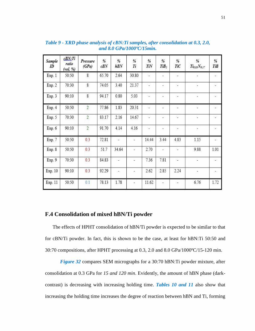
51
Table 9 - XRD phase analysis of cBN:Ti samples, after consolidation at 0.3, 2.0,
and 8.0 GPa/1000ºC/15min.
F.4 Consolidation of mixed hBN/Ti powder
The effects of HPHT consolidation of hBN/Ti powder is expected to be similar to that
for cBN/Ti powder. In fact, this is shown to be the case, at least for hBN:Ti 50:50 and
30:70 compositions, after HPHT processing at 0.3, 2.0 and 8.0 GPa/1000ºC/15-120 min.
Figure 32 compares SEM micrographs for a 30:70 hBN:Ti powder mixture, after
consolidation at 0.3 GPa for 15 and 120 min. Evidently, the amount of hBN phase (dark-
contrast) is decreasing with increasing holding time. Tables 10 and 11 also show that
increasing the holding time increases the degree of reaction between hBN and Ti, forming

52
not only larger amounts of TiB2 and TiN, but also TiB and TiN2. In both cases, there is no
residual un-reacted Ti, so that its conversion to Ti-base phases via reaction with hBN is
essentially complete. The relatively high density of the consolidated materials also reflects
conversion of hBN (ρ = 2.1 g/cm3) into higher density (ρ = 4.5-4.7 g/cm3) Ti-base phases.
The 50:50 hBN:Ti composition is an intermediate case, where there is less Ti available
initially for reaction with hBN, thus yielding smaller amounts of TiB2 and TiN phases and
a lower density.
Figure 33 shows an EDS map of a 30:70 hBN:Ti sample, after processing at 0.3
GPa/1000ºC/120 min. The observed distribution of B, N, and Ti confirms that the
composite consists of coarse hBN particles dispersed in a fine-scale TiB2/TiN composite
matrix.
(a) (b)
Figure 32 - SEM images of 30:70 hBN:Ti after consolidation at 0.3
GPa/1000oC: (a) 15 min and (b) 120 min, showing smaller fraction of hBN
particles (dark contrast) with longer holding time.

53
Table 10 - Densities of hBN:Ti samples, after consolidation at 0.1, 0.3, 2.0, and
8.0 GPa/1000ºC, showing high density of fully reacted material.
Table 11 - XRD phase analysis of hBN:Ti samples, after consolidation at 0.3,
2.0, and 8.0GPa/1000ºC.

54
Figure 33 - EDS map of 30:70 hBN:Ti sample, after processing at 0.3
GPa/1000ºC/15min, showing presence of B and N in the Ti-rich matrix phase.
F.5 Consolidation of multi-layered structures
It has been shown that, depending on the HPHT processing parameters adopted, mixtures
of cBN/Ti and hBN/Ti powders react exothermically to form a wide range of
nanocomposite structures. A cBN/Ti powder mixture transforms into a superhard cBN-
base composite, consisting of a high fraction of superhard cBN particles in a hard
TiB2/TiN nanocomposite matrix or binder phase. On the other hand, a hBN/Ti powder
mixture transforms into a hard TiB2/TiN. In both cases, compositions and processing
parameters can be adjusted to yield residual un-reacted Ti for improved toughness.
This ability to react h-BN and c-BN with Ti to produce hard and superhard
nanocomposites, often under the same HPHT processing conditions, enables multi-layered

55
structures to be fabricated in a one-step operation. In principle, such structures may be
designed to satisfy shock-impedance mismatch and shock-wave dispersion requirements
for high performance armor, and possibly provide a multi-hit capability.
Two attempts are made to fabricate layered-composite structures, comprising
alternating layers of hard and superhard phases, with interlayers of soft Ti. In the first
experiment, a 7-layer powder compact of cBN and Ti is consolidated at 0.3
GPa/750ºC/15min. The consolidated sample shows delamination at interphase interfaces,
probably due to thermal-expansion and elastic-modulus misfit stresses that develop
between the different layers. Because of the complexity of the structure observed, no
further work is planned on this material. To simplify matters, in the second experiment, a
2-layer powder compact is consolidated under the same HPHT conditions. The powder
compact (9.5 mm dia x 5 mm), Figure 34, consists of a top layer (4-mm thick) of 70:30
TiC:Ti and a bottom layer (1-mm thick) of 50:50 cBN:TiC/Ti.
After HPHT consolidation at 0.3 GPa/750ºC/15min, a monolithic sample of high
density (ρ = 4.79 g/cm3) is realized. The top layer reacts with the graphitic-carbon heater
to form a thin layer of TiC, with no evidence for residual un-reacted Ti, Figure 35(a). On
the other hand, the bottom layer reacts with the graphitic-carbon heater to form a composite
structure, comprising about 75% cBN, 24% TiC, and 1% of Ti, Figure 35(b). This result
is similar to that of previous experiments at pressures of 0.3 GPa, where Ti stabilizes the
cBN and prevents its surface decomposition into hBN. The possibility that a thin
passivation film of TiB2/TiN forms on the cBN particle surfaces, preventing further
reaction with Ti, is being investigated.

56
Figure 34 - Schematic of a bi-layered composite sample, showing thickness of
each layer and its composition.

57
(a)
(b)
Figure 35 - XRD spectra of a bi-layered composite sample, showing (a) TiC in
its top layer, and (b) cBN/TiC in its bottom layer.

58
It is noteworthy that in all experiments under reduced high pressure conditions,
including the above, the pressure requirements for processing Ti-bonded c-BN, Ti-bonded
TiB2/TiN, and layered structures are as low as 0.3 GPa, and possibly lower, so that
scalability is not an issue. In fact, it appears that conventional hot-isostatic pressing (HIP)
and sinter-HIP technologies can be used to produce ceramic armor plates of any desired
size and shape.

59
G. Discussion
The synthesis of materials by exploiting exothermic reactions, called “combustion
synthesis”, continues to engage the interest of academic and industrial researchers, since it
is a cost-effective and scalable method to produce refractory materials, ceramics,
composites and intermetallic compounds[56-65]. Combustion synthesis methods can be
broadly classified into two main types: (1) bulk synthesis, where a well-mixed powder
compact of reactants is ignited by raising the temperature to the ignition point, such that
the entire compact experiences a very fast massive transformation to the final product; and
(2) self-propagating synthesis, where reaction is initiated at some point in a powder
compact, and then propagates as a combustion wave throughout the compact, driven by an
exothermic reaction at its leading edge. The latter is called self-propagating high-
temperature synthesis (SHS). Under such processing conditions, the adiabatic reaction
temperature is high (5000 K), wave-propagation rate rapid (25 cm/s), thermal gradient
steep (105 K/cm), and cooling rate fast (105 K/s). Thus, far-from-equilibrium or metastable
phases are attainable, such as extended-solid solution, metastable intermediate, and
amorphous phases, as well as nanocrystalline (one component) and nanocomposite (two or
more components) materials. Even so, the resulting products are quite porous, typically
about 50% of theoretical density, so that further processing is needed to achieve complete
densification. Similar SHS-based methods are also used to fabricate bulk materials via
solid-solid or solid-gas reactions, and coatings by thermal spraying[66-70].
When dealing with powder processing, pressure-assisted SHS is favored, since the final
densified product is obtained directly by combining powder synthesis and consolidation in
a single operation. The method described herein, called reactive-HPHT synthesis, is one

60
such method, since reaction between the constituent phases in a well-mixed powder
compact is performed under a sustained pressure at high temperature, thus ensuring a pore-
free product. A feature of the process is its ability to transform the same starting powder
composition into different products by varying reaction pressure at a fixed reaction
temperature or vice versa. For example, reactive-HPHT processing of a 50:50 composition
of cBN:Ti powder at 0.3, 2.0 and 8.0 GPa/1000ºC/15 min yields three distinct composite
products. At 8.0 GPa, no detectable reaction of cBN with Ti occurs, resulting in a Ti-
bonded cBN composite. In striking contrast, at 0.3 GPa, complete reaction between cBN
and Ti occurs, resulting in a TiB2/TiN-bonded cBN composite. On the other hand, at 2.0
GPa, reaction between Ti and cBN is incomplete, resulting in a Ti/TiN-bonded c-BN
composite with no detectable TiB2. Similar reactions occur for other compositions and for
different starting materials, e.g. hBN instead of cBN. Since reaction between Ti and BN is
exothermic, reaction (1) below, the thermal transient generated during processing,
irrespective of reaction mode (bulk or self-propagating), facilitates pressure-assisted
sintering to full density, while achieving an ultrafine-grained structure due to the rapid self-
quenching experienced by the consolidated product.
2BN + 3Ti → TiB2 + 2TiN (ΔH = - 467 kJ/mol) (1)
In the procedure adopted for reactive-HPHT processing of Ti with BN, after the
application of high pressure to a mixed-powder compact at ambient temperature, the
compact is heated to 1000ºC and held at this temperature for 15 min. Of particular interest
is the effect on reaction kinetics of the scale of particle mixing in the initial powder
compact. Initial results indicate that fine-scale mixing of the reactants causes very rapid
conversion, even detonation, resulting in an ultra-fine or nanostructured composite; such

61
is not the case for coarse-scale mixing of the reactants, where time-dependent reaction
processing is observed. According to reaction (1), 2 mol of TiN are generated for every 1
mol of TiB2, which corresponds to about a 70:30 ratio of the two phases. At this ratio, a
bicontinuous nanocomposite is formed in which the constituent nanophases are
interpenetrating in three dimensions. Such a composite structure is known to resist
coarsening at high temperature, so that a host of high-temperature applications are
conceivable, such as heat/corrosion-resistant ceramics for gas-turbine and rocket engines.
An addition of more cBN than is required to complete reaction (1) yields a dispersion
of un-reacted cBN particles in a TiB2/TiN matrix, reaction (2), whereas an addition of more
Ti than required to complete reaction (1) yields a dispersion of un-reacted Ti particles in
a TiB2/TiN matrix, reaction (3). Both types of composites have their potential uses; the
former for machine tools requiring high hardness and stiffness, and the latter for drill bits
requiring high hardness and toughness. Layered superhard-faced cBN composites,
designed to satisfy impedance mismatch requirements, also have potential applications in
lightweight personnel and vehicular armor.
3BN + 3Ti → TiB2 + 2TiN + BN (un-reacted) (2)
2BN + 4Ti → TiB2 + 2TiN + Ti (un-reacted) (3)
Similar effects are expected for reactive-HPHT processing of BN with Ti, Zr, Hf or
mixtures thereof, which opens opportunities for the synthesis of ultra-high temperature
ceramics for the next generation of hypersonic vehicles. Currently, the most promising
materials are HfB2, HfC, HfN and their composites, because of their exceptionally high
melting points and good oxidation resistance; the latter due to the formation upon oxidation

62
of a thermally-stable protective scale of HfO2. Such is not the case for Ti-base compounds,
where oxide scales are not stable at high temperatures.
In principle, other compound ceramics (e.g. B4C and Si3N4) and elemental-powder
mixtures (e.g. B and C) may also react with Ti, Zr or Hf to form nanostructured composites.
For example, reactive-HPHT processing of an appropriate stoichiometric mixture of
B4C+BN+Ti powders should yield a triphasic nanocomposite comprising three distinct
phases - TiB2+TiC+TiN in which one or more phases are extended solid solutions. An
important feature of the process is that it can be adapted to make use of today’s hot pressing
and hot-isostatic pressing technologies, thus there is the prospect of scaling the technology
at relatively low cost. Moreover, tailoring the mechanical properties of such a multi-phasic
nanocomposite to satisfy the performance requirements of a specific application seems
technically feasible. This may provide sufficient incentive to industry to commercialize
this new class of nanocomposite ceramics for high-temperature structural applications.
Several publications give detailed descriptions of SHS-based methods to produce
refractory materials, including carbides, borides, nitrides, silicides and intermetallics
[71-73]. Particularly relevant to the present discussion is research on dynamic compaction
to produce TiB2/TiC composites[74-76]. The experimental setup enables reactive
consolidation of a well-mixed B4C and Ti powder in two sequential steps. First, the
reactants are ignited by an electrical discharge at the top of a green compact, thereby
generating a combustion wave that propagates downward through the entire compact.
Second, upon reaching the sample base, an explosive is detonated such that a shock wave
propagates through the adiabatically-heated compact. The effect is to achieve rapid powder
densification, probably assisted by some melting of the reacting phases. The final fully-

63
dense composite consists of a uniform distribution of TiB2 and TiN phases, with average
grain size about 3.5 µm.
The present method differs from this earlier work in that much greater flexibility is
afforded in control of the scale of the final grain size, ranging from submicron- to nano-
scale dimensions, while also retaining some un-reacted Ti to enhance toughness. This is an
important consideration, since most of the projected applications for this new class of hard
and superhard composites require some degree of toughness. Historically, this was also a
requirement in the development of WC/Co hardmetals, where, without the presence of a
ductile-Co binder phase for the hard/brittle WC phase, applications would be severely
limited. Hence, in future work, we will place much greater emphasis on trade-offs between
hardness and toughness by varying the volume fraction ratio of superhard cBN phase and
ductile Ti, as has been done for WC/Co hardmetals for decades. In fact, each application
today specifies volume fraction ratio of WC/Co phases to obtain just the right combination
of hardness, compressive strength, and fracture toughness. Interestingly, in the most recent
development in the field, a bimodal-structured WC/Co is gaining prominence, where
coarse-grained WC particles are bonded together with a WC/Co nanocomposite. The effect
is to dramatically enhance abrasive-wear resistance, since undercutting of the coarse WC
particles is prevented.
Looking ahead, therefore, it seems likely that further development of cBN/Ti-base
composites will follow a similar path in properties optimization for machine tools and rock-
drill bits, where abrasive wear is a serious performance limiting factor. On the other hand,
for lightweight armor applications, it seems likely that lower density cBN/Al-base
compositions will be preferred. In this case, there is interest in developing a superhard-

64
faced composite, comprising an outer layer of superhard cBN and a backing layer of tough
Ti-bonded TiB2/TiN nanocomposite, with a compositionally graded interface to enhance
bond strength between the dissimilar materials. Development of this new class of
lightweight superhard/tough layered composites has now become an important part of an
expanded research effort.

65
H. Future Work
Recognizing the present accomplishments, the following research areas should be
considered for future work:
High-pressure synthesis cBN powder using Mg as a catalyst has been demonstrated, as
well as its HPHT consolidation into monolithic nanocrystalline cBN. It remains to
eliminate residual hBN in the consolidated product, since its presence adversely affects
hardness, strength, and particularly toughness. To do so, the use of sintering aids will be
investigated. In addition, a new in-house source of high purity cBN nanopowder,
synthesized by plasma decomposition of a borane-ammonia precursor, will be used in
future consolidation work. At the same time, we will collaborate with Diamond
Innovations to investigate scaling of the processing technology, with the objective of being
able to fabricate, for the first time, large panels of superhard nanocrystalline cBN for
lightweight personnel and vehicular armor.
High-pressure consolidation of a new class of cBN/Ti-base composites, comprising a high
fraction of superhard cBN particles in a tough Ti matrix or binder phase, has been
demonstrated. Most importantly, it has been shown that the pressure requirements to
achieve complete consolidation is as low as 0.1 GPa, so that scaling using HIP technology
becomes technically feasible. To explore this option, we will collaborate with Diamond
Innovations.
High-pressure consolidation of a multi-layered structure has been demonstrated, but much
remains to be done to suppress undesirable reactions with the graphitic-carbon heater, and
to control interphase-interface properties to avoid delamination between layers due to
thermal-expansion and elastic-modulus misfit stresses.

66
From a more fundamental perspective, it is of interest to obtain a better understanding of
mechanisms and kinetics involved in HPHT powder consolidation, when it is accompanied
by a strong exothermic reaction. A preliminary assessment indicates that an uncontrollable
run-away reaction can be avoided by adjusting the mixing scale of the reacting powders.
.

67
Appendix A
Considerable effort has been devoted to polishing nanocrystalline cBN samples in order to
make reliable hardness measurements. However, even using the best grinding and
polishing practice, the surface finish is poor. Figure A.1 shows an example of a pitted
surface on a sample of powder #1 after consolidation at 8.0 GPa/1000ºC/15 min. The
pitting effect is ascribed to grain pull-out during polishing with a fine-diamond paste. Also
shown is a Vickers hardness indent (arrow) that is located in a pitted area of the sample.
Not surprisingly, the measured hardness at this location is lower (40-50 GPa) than that of
nano-grained material (85 GPa). Even so, scratch tests indicate an exceptionally hard
material.
36Figure A.1 - Example of the pitted surface of a consolidated sample of
powder#1, showing extensive grain pullout due to polishing. Also shown is a
Vickers hardness indent (arrow).
Surface pitting is such a reproducible effect in diamond-polished samples that it must
reflect an intrinsic characteristic of the HPHT-consolidated cBN. One possible explanation

68
is that the superhard material contains internal micro-strains that are not relaxed at the
1000ºC processing temperature. Hence, a post-annealing treatment, say at a temperature
>1600ºC may be necessary to induce recovery and/or recrystallization, thereby achieving
a strain-free nanocrystalline product.
To test this hypothesis, a comparison will be made of polished surfaces on as-
consolidated and post-annealed samples. In addition, the synchrotron method, developed
by Tsakalakos et al. [43], will be used to measure the internal-strain distribution, and
changes with increasing depth in the consolidated disc-shaped sample. Information on
sample texturing may also be obtained, which is of interest since evidence for texturing is
observed by TEM, Figure 25. It is an interesting question whether micro-strained cBN
offers an advantage in terms of ballistic-impact performance, since it may promote
powderization at the impact location, accompanied by significant energy absorption.
Since there are many small areas of the pitted sample that are quite smooth in
appearance, Figure A.1, nanoindentation testing provides a means to measure hardness in
such areas. Results obtained for this particular sample are presented in Figure A.2. As
expected, the nanoindenter is able to obtain data for smooth areas of the sample. The upper
hardness value is ~75 GPa, in line with a reported value of 85 GPa [11]. As an additional
point of comparison, the hardness of nanocrystalline cBN is well over 9 on Mohs scale.

69
37 Figure A.2 - Nanoindentation data for a nano-cBN sample, after HPHT
consolidation of powder #1 at 8.0 GPa/1000ºC/15min
A similar problem is encountered in polishing consolidated samples of powder #2,
processed under essentially the same conditions as powder #1. However, in this case, the
polishing problem is exacerbated by the presence of residual micro-porosity in the HPHT-
processed cBN. Thus, a sample processed at 8.0 GPa/1600ºC/10 min, with 93.7 %
theoretical density, gives a relatively low hardness value of 20 GPa, which is ascribed to
the presence of residual micro-porosity. Even so, the hardness of the consolidated cBN is
well above 9 on Mohs scale.
With regard to cBN/Ti compositions, once again difficulties are encountered in
obtaining smooth surfaces on consolidated samples, irrespective of whether the starting
material is powder #1 or powder #2. Best results are obtained for 50:50 cBN:Ti mixtures,
using powder #2, consolidated at 0.3 GPa/1000ºC/15 min. Vickers hardness values at
loads well into the macro-hardness range give values of 35 GPa, whereas reported values
for TiN (18-24 GPa) and TiB2 (25-35 GPa). The higher hardness of the HPHT-processed

70
material is attributed to its nanocomposite structure. Unfortunately, due to polishing
limitations, it is not possible to evaluate fracture toughness. To overcome this shortcoming,
additional work is being performed to improve polishing procedure so as to observe corner
cracking at indents, as required to determine toughness.
To summarize, presently there is some uncertainty in the hardness values of HPHT-
processed samples due to pitting of their polished surface. Surface pitting is attributed to
two main causes: high levels of internal micro-strains and/or micro-porosity. Modified
HPHT processing parameters, along with improved polishing and evaluation techniques,
will be investigated in future work. Both are important to the continued development of
nanostructured hard and superhard cBN-base materials for lightweight armor applications.

71
References
[1] J. Wentorf and E. Al., “Diamond tools for machining - US Patent 3745623.” 1973.
[2] R. H. Wentorf, R. C. Devries, and F. P. Bundy, “Sintered superhard materials.,”
Science, vol. 208, no. 4446, pp. 873–80, May 1980.
[3] R. H. Wentorf, “Synthesis of the Cubic Form of Boron Nitride,” J. Chem. Phys., vol.
34, no. 3, p. 809, 1961.
[4] F. P. Bundy and R. H. Wentorf, “Direct Transformation of Hexagonal Boron Nitride
to Denser Forms,” J. Chem. Phys., vol. 38, no. 5, p. 1144, 1963.
[5] J. Angseryd, M. Elfwing, E. Olsson, and H.-O. Andrén, “Detailed microstructure of
a cBN based cutting tool material,” Int. J. Refract. Met. Hard Mater., vol. 27, no. 2,
pp. 249–255, Mar. 2009.
[6] C. S. Pande and K. P. Cooper, “Nanomechanics of Hall–Petch relationship in
nanocrystalline materials,” Prog. Mater. Sci., vol. 54, no. 6, pp. 689–706, Aug.
2009.
[7] H. Kuwahara, N. Mazaki, M. Takahashi, T. Watanabe, X. Yang, and T. Aizawa,
“Mechanical properties of bulk sintered titanium nitride ceramics,” Mater. Sci. Eng.
A, vol. 319–321, pp. 687–691, Dec. 2001.
[8] K. M. Taylor and C. Lenie, “Some Properties of Aluminum Nitride,” J.
Electrochem. Soc., vol. 107, no. 4, p. 308, 1960.
[9] Y. Tian, B. Xu, D. Yu, Y. Ma, Y. Wang, Y. Jiang, W. Hu, C. Tang, and Y. Gao,
“Ultrahard nanotwinned cubic boron nitride,” Nature, vol. 493, pp. 385–388, 2013.
[10] ASM International, Engineered Materials Handbook Volume 4, Ceramics and
Glasses. ASM International, 1991, p. 819.
[11] N. Dubrovinskaia, V. L. Solozhenko, N. Miyajima, V. Dmitriev, O. O. Kurakevych,
and L. Dubrovinsky, “Superhard nanocomposite of dense polymorphs of boron
nitride: Noncarbon material has reached diamond hardness,” Appl. Phys. Lett., vol.
90, no. 10, p. 101912, 2007.
[12] V. L. Solozhenko, O. O. Kurakevych, and Y. Le Godec, “Creation of nanostuctures
by extreme conditions: high-pressure synthesis of ultrahard nanocrystalline cubic
boron nitride.,” Adv. Mater., vol. 24, no. 12, pp. 1540–4, Mar. 2012.
[13] H. Lee and R. F. Speyer, “Hardness and Toughness of Pressureless Sintered Boron
Carbide (B4C ),” J. Am. Ceram. Soc., vol. 93, pp. 1291–1293, 2002.

72
[14] R. G. Munro, “Material properties of titanium diboride,” J. Res. Natl. Ist. Stand.,
vol. 105, no. 5, pp. 709–720, 2000.
[15] J. Tse, D. Klug, and F. Gao, “Hardness of nanocrystalline diamonds,” Phys. Rev. B,
vol. 73, no. 14, p. 140102, Apr. 2006.
[16] V. L. Solozhenko and O. O. Kurakevych, “Chemical interaction in the B–BN system
at high pressures and temperatures.,” J. Solid State Chem., vol. 182, no. 6, pp. 1359–
1364, Jun. 2009.
[17] CAlphad Thermodynamic Database, “Titanium-Boron Phase Diagram.” p. 3500,
2008.
[18] K. Leinenweber, J. Tyburczy, T. Sharp, E. Soignard, D. Tamara, W. Petuskey, Y.
Wang, and J. Mosenfelder, “Cell assemblies for reproducible multi-anvil
experiments ( the COMPRES assemblies ),” Am. Mineral., vol. 97, pp. 353–368,
2012.
[19] N. Shin-ichi, Hirano, Naka Shigeharu, “Methods for Preparing Cubic Boron Nitride
Sintered Body US Patent 4,545,968,” 1985.
[20] O. O. Kurakevych and V. L. Solozhenko, “Experimental study and critical review
of structural, thermodynamic and mechanical properties of superhard refractory
boron suboxide B6O,” J. Superhard Mater., vol. 33, no. 6, pp. 421–428, Dec. 2011.
[21] Y. Tian, B. Xu, and Z. Zhao, “Microscopic theory of hardness and design of novel
superhard crystals,” Int. J. Refract. Met. Hard Mater., vol. 33, pp. 93–106, Jul. 2012.
[22] R.-Q. Zhang, T.-H. Lee, B.-D. Yu, C. Stampfl, and A. Soon, “The role of titanium
nitride supports for single-atom platinum-based catalysts in fuel cell technologyw,”
Phys. Chem. Chem. Phys., vol. 14, no. 48, pp. 16552–7, Dec. 2012.
[23] V. L. Solozhenko and V. Z. Turkevich, “Refined Phase Diagram of Boron Nitride,”
Am. Chem. Soc., vol. 103, pp. 2903–2905, 1999.
[24] C. S. DANA, James Dwight, Hurlbut, Dana’s Manual of Minerology (17th Edition),
17th Editi. New York, Chapman HAll, 1959, pp. 78–89.
[25] V. L. Solozhenko, D. Häusermann, M. Mezouar, and M. Kunz, “Equation of state
of wurtzitic boron nitride to 66 GPa Equation of state of wurtzitic boron nitride to
66 GPa,” Appl. Phys. Lett., vol. 72, number, no. 1691, pp. 1691–1693, 1998.
[26] Z. Pan, H. Sun, Y. Zhang, and C. Chen, “Harder than Diamond: Superior Indentation
Strength of Wurtzite BN and Lonsdaleite,” Phys. Rev. Lett., vol. 102, no. 5, p.
055503, Feb. 2009.

73
[27] J. E. Laurence Vel, Gerard Demazeau, “Cubic boron nitride: synthesis,
physiochemical properties and applications,” Mater. Sci. Eng. B, vol. 10, no. 2, pp.
149–164, 1991.
[28] J. Schmidt, M. Boehling, U. Burkhardt, and Y. Grin, “Preparation of titanium
diboride TiB 2 by spark plasma sintering at slow heating rate,” Sci. Technol. Adv.
Mater., vol. 8, no. 5, pp. 376–382, Jul. 2007.
[29] R. Riedel, Handbook of Ceramic Hard Materials, Volume 1. Wiley-VCH, 2004, p.
185.
[30] J. L. Wreidt, H.A. Murray, “The N-Ti (Nitrogen-Titanium) System,” Bull. Alloy
Phase Diagrams, vol. 8, no. 4, pp. 378–379, 1987.
[31] K. Yamada, Shimada, “Properties of Bulk Titanium Nitiride,” Am. Ceram. Soc.
Bull., vol. 59, p. 611, 1980.
[32] H. Okamoto, “Phase Diagram of Titanium Nitride,” J. Phase Equilibria Diffus., vol.
34, no. 2, pp. 151–152, Oct. 2012.
[33] S. Deutsch, “High Pressure Phase Transformations in Polycrystalline Yttrium
Oxide,” Rutgers University, Dept of Matl. Science & Engineering, 2012.
[34] O. A. Voronov and B. H. Kear, “Method for Rapidly Synthesizing Monolithic
Polycrystalline Diamond Articles US PAtent 8,021,639 B1,” 2011.
[35] O. A. Voronov and L. S. Kashevarova, “Low-Temperature Synthesis of Cubic
Boron Nitride and Diamond Under high Pressure,” in electrochemical Society
Proceddings Volume 95-4, 1995, pp. 318–323.
[36] O. A. Voronov, G. S. Tompa, and B. H. Kear, “High Pressure-High Temperature
Device for making Diamond Materials,” Electrochem. Soc., vol. 25, pp. 264–271,
2001.
[37] N. Velisavljevic, S. Macleod, and H. Cynn, “Titanium Alloys at Extreme Pressure
Conditions,” Surf. Coatings Technol., vol. 125, pp. 335–340, 2000.
[38] O. Voronov, “Pressure Dependency of Tm (oC) of Mg, Al, Ti Pressure (GPa),” p.
2500, 2000.
[39] J. D. Cullity, Elements of X-Ray Diffraction, Second. Addison-Wiley, 1978, p. 102.
[40] MDI Coporation, “Jade Software Ver 9.6.0 4-11-14.” 2014.
[41] F. Karlsruhe, “Inorganic Crystal Structure Database (ICSD).” 2014.

74
[42] R. L. Jenkins, R Snyder, Introduction to X-ray Powder Diffractometry. John Wiley
and Sons, Inc., 1996, pp. 89–91.
[43] T. Tsakalakos and M. Croft, “XRD Strain and Stress Determination in
Nanostructured Films and Coatings,” in NATO Advanced Research Workshop on
Nanostructured Films and Coating, 2000, pp. 223–230.
[44] B. E. Warren, X-Ray Diffraction. Addsion-Wesley Publishing Co., 1969, pp. 251–
254.
[45] H. P. Klug and L. E. Alexander, X-Ray Diffraction Procedures. John Wiley & Sons
Inc., 1974, pp. 687–703.
[46] J. Ghosh, S. Mazumdar, M. Das, S. Ghatak, and a. K. Basu, “Microstructural
characterization of amorphous and nanocrystalline boron nitride prepared by high-
energy ball milling,” Mater. Res. Bull., vol. 43, no. 4, pp. 1023–1031, Apr. 2008.
[47] R. A. Young, “Crystal Imperfection Broadening and peak shape in the Reitveld
Method,” in The Reitveld Method, Oxford University Press 1995, 1995, pp. 133–
163.
[48] J. J. Friel, X-Ray and Image Analysis in Electron Microscopy, 2nd ed. Princeton
Gamma Tech, 2003, p. 97.
[49] Zeiss, Zeiss Field Emission Scanning Electron Microscope Users Guide. 2005, p.
all.
[50] D. Williams and B. Carter, Transmission electron Microscopy. Plenum Press, 1996.
[51] T. L. Heath, The Works of Archimedes, 1st ed. London: Cambridge University Press,
1897, p. 65.
[52] ASTM International, “ASTM E384 Standard Test Method for Knoop and Vickers
Hardness of Materials.” ASTM International, West Conshohocken, PA, pp. 1–43,
2014.
[53] ASTM International, “ASTM C1327 Standard Test Method for Vickers Indentation
Hardness of Advanced Ceramics.” ASTM International, West Conshohocken, PA,
pp. 1–9, 2014.
[54] J. Morgiel and E. Benko, “Microstructure of boron nitride sintered with titanium,”
Mater. Lett., vol. 25, no. October, pp. 49–52, 1995.
[55] M. T. B. Wreidt, Murray, “Phase Diagram of Binary titanium Alloys,” in ASM
Inetrnational, 1990, p. 176.

75
[56] I. Song, L. Wang, and M. Wixom, “Self Propogating High Temperature Synthesis
and Dynamic Compaction of titanium diboride/titanium carbide Composites,” J.
Mater. Sci., vol. 35, pp. 2611–2617, 2000.
[57] E. K. Storms, The Refractory Carbides. New York: Academic Press, 1967.
[58] L. E. Toth, Transition Metal Carbides and Nitrides. New York: Academic Press,
1971.
[59] J. A. Puszynski, Carbide, Nitride, and Boride Materials. London: Chapman & Hall,
1997, pp. 183–228.
[60] Z. A. Munir and U. Anselmi-Tamburini, “Self-propogating exothermic reactions:
the synthesis of high temperature materials by combustion,” Mater. Sci. Reports,
vol. 3, no. 7, pp. 277–365, 1989.
[61] J. J. Moore and H. J. Feng, “Combustion Synthesis of Advanced Materials,” Prog.
Mater. Sci., vol. 39, pp. 277–365, 1995.
[62] R. Pampuch, “Advanced HT Ceramic Materials via Solid Combustion,” J. Eur.
Ceram. Soc., vol. 19, pp. 2395–2404, 1999.
[63] J. B. Holt and Z. A. Munir, “Combustion Synthesis of Titanium Carbide, theory and
experiment,” J. Mater. Sci., vol. 21, pp. 251–259, 1996.
[64] F. Bernard and E. Gaffet, “Mechanical Alloying in SHS Research,” Int. J. SHS, vol.
10, no. 2, pp. 109–132, 2001.
[65] S. . Roy, A. Biswas, and S. Banerjee, “Self-propogating high-Temperature Synthesis
of Titanium Borides,” Bull. Mater. Sci., vol. 16, no. 5, pp. 347–356, 1993.
[66] R. Pampuch, “Some Fundamental Versus Practical Aspects of Self Propogating
High-temperature Synthesis,” Solid State Ionics, vol. 101, pp. 899–907, 1997.
[67] S. K. Roy and A. Biswas, “Combustion Synthesis of TiB and TiB2 Under Vacuum,”
J. Mater. Sci. Lett., vol. 13, p. 371, 1994.
[68] US National Research Council, Strategic Technologies for the Army of the Twenty-
First Century. Washington, D.C: National Academy Press, 1992, pp. 159–169.
[69] J. J. Moore and H. J. Feng, Progress in Material Science, Combustion Synthesis of
Advanced Materials. Tarrytown New York: Elsevier Science Ltd., 1995, pp. 241–
73.
[70] R. Mackenzie, Differential Thermal Analysis, 2nd ed. London: Academic Press,
1970, pp. 38–59.

76
[71] S. D. Dunmead, Carbide, Nitride, and Boride Materials Synthesis and Processing.
London: Chapman & Hall, 1997, pp. 229–272.
[72] A. G. Merzhanov and S. Y. Shraivker, Self Propogating high temperature synthesis
of carbides, nitrides, and borides. Netherlands: Kluwer Academic Publishers, 1999,
pp. 205–202.
[73] T. Kim and M. S. Wooldridge, “Catalytically Assisted Self-propagating High-
temperature Synthesis of tantalum carbide Powders,” J. Am. Ceram. Soc., vol. 84,
no. 5, p. 2001, 2001.
[74] L. Wang, M. Wixom, and L. T. Thompson, “Structural and Mechanical Properties
of TiB2 and TiC Prepared by self-Propogating high-temperature Synthesis/dynamic
Compaction,” J. Mater. Sci., vol. 29, no. 2, pp. 534–543, 1994.
[75] S. K. Mishra, S. K. Das, and V. Shcherbakov, “Effect of Alumina Diluent on the
Fabrication of In-Situ Al 2 O 3 -Ti / ZrB 2 Composite by Self Propagating High
Temperature Synthesis Dynamic Compaction,” Metall. Mater. Trans. B, vol. 37B,
pp. 2006–2641, 2005.
[76] P. Boogard, “Dynamic Compaction of Ceramics,” Delfy University, 1995.