by chris staiger • bakersfield model yacht club ... chris staiger • bakersfield model yacht club...
TRANSCRIPT
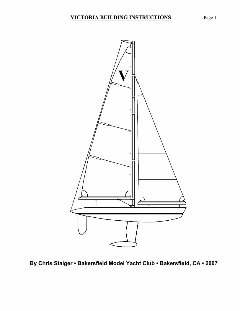
VICTORIA BUILDING INSTRUCTIONS Page 1
By Chris Staiger • Bakersfield Model Yacht Club • Bakersfield, CA • 2007
VICTORIA BUILDING INSTRUCTIONS Page 2
Hull & Deck
1) Inspect Kit components for completeness and possible damage. Carefully check hull for molding defects or ‘thin spots.’ If obvious thin spots are found, they may need to be reinforced with a layer of fiberglass cloth and epoxy resin. Assemble boat stand from kit-supplied plywood.
2) Use a SHARP utility knife to CAREFULLY cut open the hatch. Support the hull firmly, and carefully cut
along the oval indentation. With constant firm pressure the material should slowly yield and allow the knife blade to slowly traverse the oval cutout. Once removed, the edges of the oval hatch opening can be sanded smooth with 400 grit paper.
3) Using a sanding block with 400 grit paper, lightly sand the hull/deck seam to remove any excess flashing.
Next, wet-sand the hull bottom beginning with 400 grit paper, and finishing with 600 grit paper. This is important as the hull surface has a very fine ‘orangepeel’ texture that will slow it down. Even if you later intend to paint the hull, sanding will help the paint adhere better and provide a smoother base surface resulting in a better paint job. If you do not intend to paint; the hull surface can be finished by wet-sanding with increasingly finer grades of paper, ending with 1000 grit, and finishing-up with plastic polish to obtain a smooth, shiny finish.
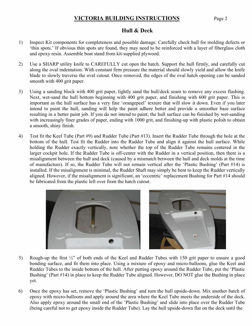
4) Test fit the Keel Tube (Part #9) and Rudder Tube (Part #13). Insert the Rudder Tube through the hole at the
bottom of the hull. Test fit the Rudder into the Rudder Tube and align it against the hull surface. While holding the Rudder exactly vertically, note whether the top of the Rudder Tube remains centered in the larger cockpit hole. If the Rudder Tube is off-center with the Rudder in a vertical position, then there is a misalignment between the hull and deck (caused by a mismatch between the hull and deck molds at the time of manufacture). If so, the Rudder Tube will not remain vertical after the ‘Plastic Bushing’ (Part #14) is installed. If the misalignment is minimal, the Rudder Shaft may simply be bent to keep the Rudder vertically aligned. However, if the misalignment is significant, an ‘eccentric’ replacement Bushing for Part #14 should be fabricated from the plastic left over from the hatch cutout.
5) Rough-up the first ½” of both ends of the Keel and Rudder Tubes with 150 grit paper to ensure a good
bonding surface, and fit them into place. Using a mixture of epoxy and micro-balloons, glue the Keel and Rudder Tubes to the inside bottom of the hull. After putting epoxy around the Rudder Tube, put the ‘Plastic Bushing’ (Part #14) in place to keep the Rudder Tube aligned. However, DO NOT glue the Bushing in place yet.
6) Once the epoxy has set, remove the ‘Plastic Bushing’ and turn the hull upside-down. Mix another batch of
epoxy with micro-balloons and apply around the area where the Keel Tube meets the underside of the deck. Also apply epoxy around the small end of the ‘Plastic Bushing’ and slide into place over the Rudder Tube (being careful not to get epoxy inside the Rudder Tube). Lay the hull upside-down flat on the deck until the
VICTORIA BUILDING INSTRUCTIONS Page 3
epoxy sets. Once the epoxy has set, turn the hull right-side-up and wick a small amount of Plastic Cement around the “Plastic Bushing’ to glue it firmly into the cockpit surface and seal the joint.
7) Glue Hatch Cover Rail (Part #30) into place using Plastic Cement. Use clothespins or binder clamps to hold
Rail in place while the glue dries. Plug two small holes in cockpit bulkhead with tips cut from short eyelets (Part #23). Cut tips off with a razor blade, insert them into the holes and glue in place with Plastic Cement.
Keel Assembly
8) Inspect Keel Bulb (Part #7), looking for any obvious hollows or dents. If filling and repainting is desired (recommended), sand entire Bulb with 220 grit paper making sure to ‘rough-up’ the entire surface. Fill any significant hollows or dents with a fine, Polyester-based Metal filler. After filler sets, sand smooth with 320 grit.
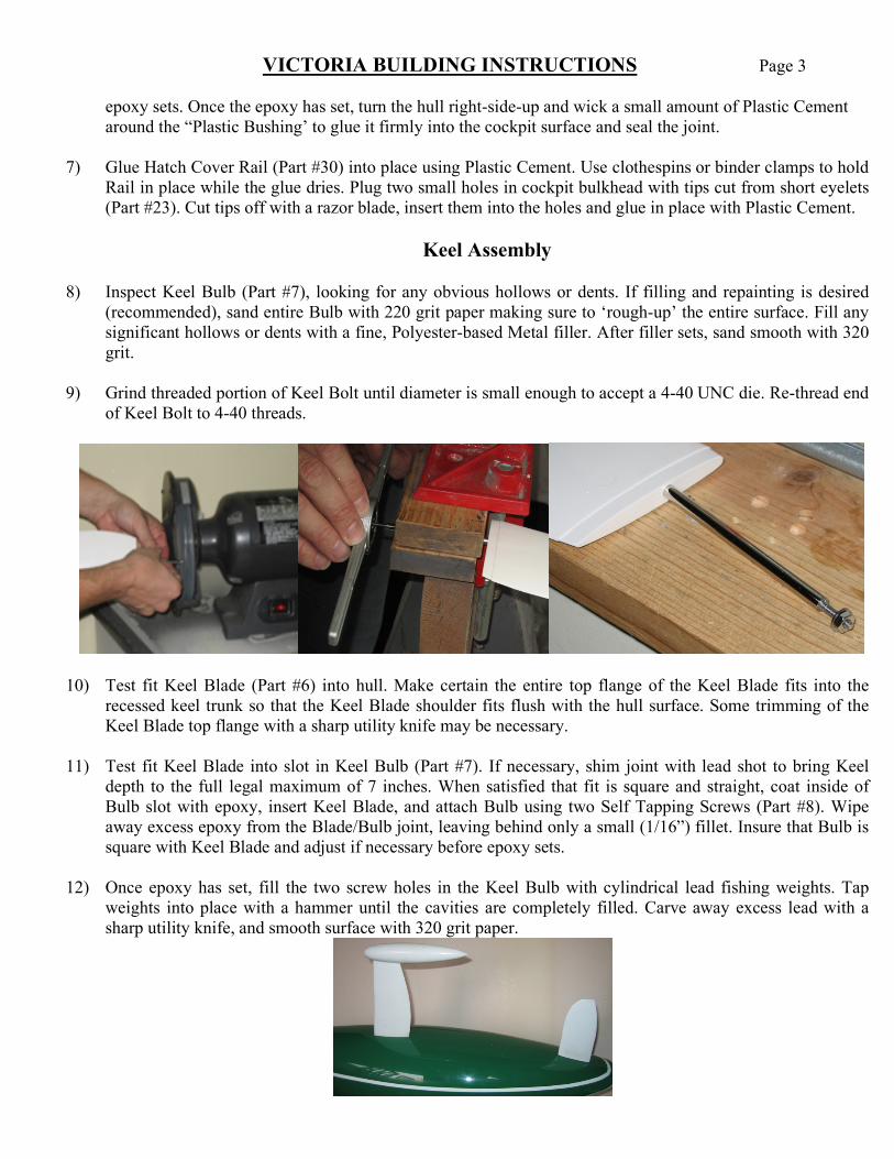
9) Grind threaded portion of Keel Bolt until diameter is small enough to accept a 4-40 UNC die. Re-thread end of Keel Bolt to 4-40 threads.
10) Test fit Keel Blade (Part #6) into hull. Make certain the entire top flange of the Keel Blade fits into the
recessed keel trunk so that the Keel Blade shoulder fits flush with the hull surface. Some trimming of the Keel Blade top flange with a sharp utility knife may be necessary.
11) Test fit Keel Blade into slot in Keel Bulb (Part #7). If necessary, shim joint with lead shot to bring Keel
depth to the full legal maximum of 7 inches. When satisfied that fit is square and straight, coat inside of Bulb slot with epoxy, insert Keel Blade, and attach Bulb using two Self Tapping Screws (Part #8). Wipe away excess epoxy from the Blade/Bulb joint, leaving behind only a small (1/16”) fillet. Insure that Bulb is square with Keel Blade and adjust if necessary before epoxy sets.
12) Once epoxy has set, fill the two screw holes in the Keel Bulb with cylindrical lead fishing weights. Tap
weights into place with a hammer until the cavities are completely filled. Carve away excess lead with a sharp utility knife, and smooth surface with 320 grit paper.
VICTORIA BUILDING INSTRUCTIONS Page 4
13) Fill any remaining hollows, voids or dents in the Keel Bulb with Polyester metal filler. After filler has set, sand entire Bulb beginning with 320 grit paper and finishing with 400 grit. Keel Bulb (& Blade) may now be primed and painted if desired.
Deck Hardware Installation
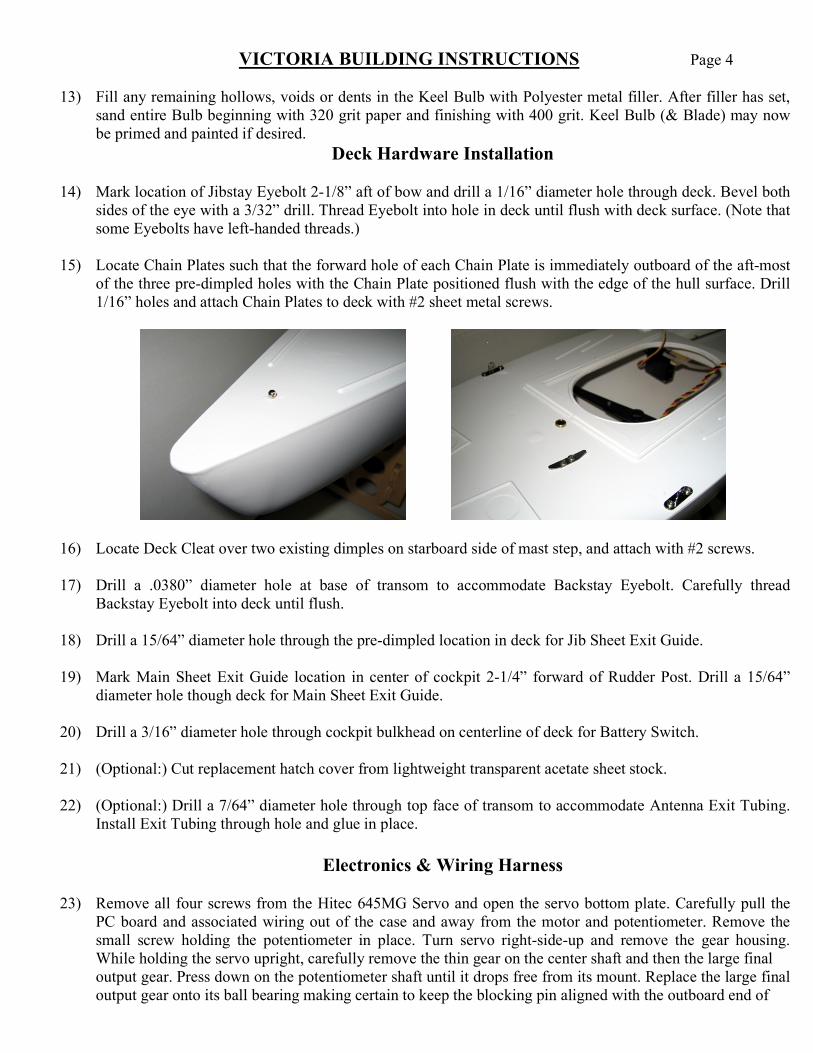
14) Mark location of Jibstay Eyebolt 2-1/8” aft of bow and drill a 1/16” diameter hole through deck. Bevel both sides of the eye with a 3/32” drill. Thread Eyebolt into hole in deck until flush with deck surface. (Note that some Eyebolts have left-handed threads.)
15) Locate Chain Plates such that the forward hole of each Chain Plate is immediately outboard of the aft-most
of the three pre-dimpled holes with the Chain Plate positioned flush with the edge of the hull surface. Drill 1/16” holes and attach Chain Plates to deck with #2 sheet metal screws.
16) Locate Deck Cleat over two existing dimples on starboard side of mast step, and attach with #2 screws. 17) Drill a .0380” diameter hole at base of transom to accommodate Backstay Eyebolt. Carefully thread
Backstay Eyebolt into deck until flush. 18) Drill a 15/64” diameter hole through the pre-dimpled location in deck for Jib Sheet Exit Guide.
19) Mark Main Sheet Exit Guide location in center of cockpit 2-1/4” forward of Rudder Post. Drill a 15/64”
diameter hole though deck for Main Sheet Exit Guide. 20) Drill a 3/16” diameter hole through cockpit bulkhead on centerline of deck for Battery Switch. 21) (Optional:) Cut replacement hatch cover from lightweight transparent acetate sheet stock. 22) (Optional:) Drill a 7/64” diameter hole through top face of transom to accommodate Antenna Exit Tubing.
Install Exit Tubing through hole and glue in place.
Electronics & Wiring Harness
23) Remove all four screws from the Hitec 645MG Servo and open the servo bottom plate. Carefully pull the PC board and associated wiring out of the case and away from the motor and potentiometer. Remove the small screw holding the potentiometer in place. Turn servo right-side-up and remove the gear housing. While holding the servo upright, carefully remove the thin gear on the center shaft and then the large final
output gear. Press down on the potentiometer shaft until it drops free from its mount. Replace the large final output gear onto its ball bearing making certain to keep the blocking pin aligned with the outboard end of
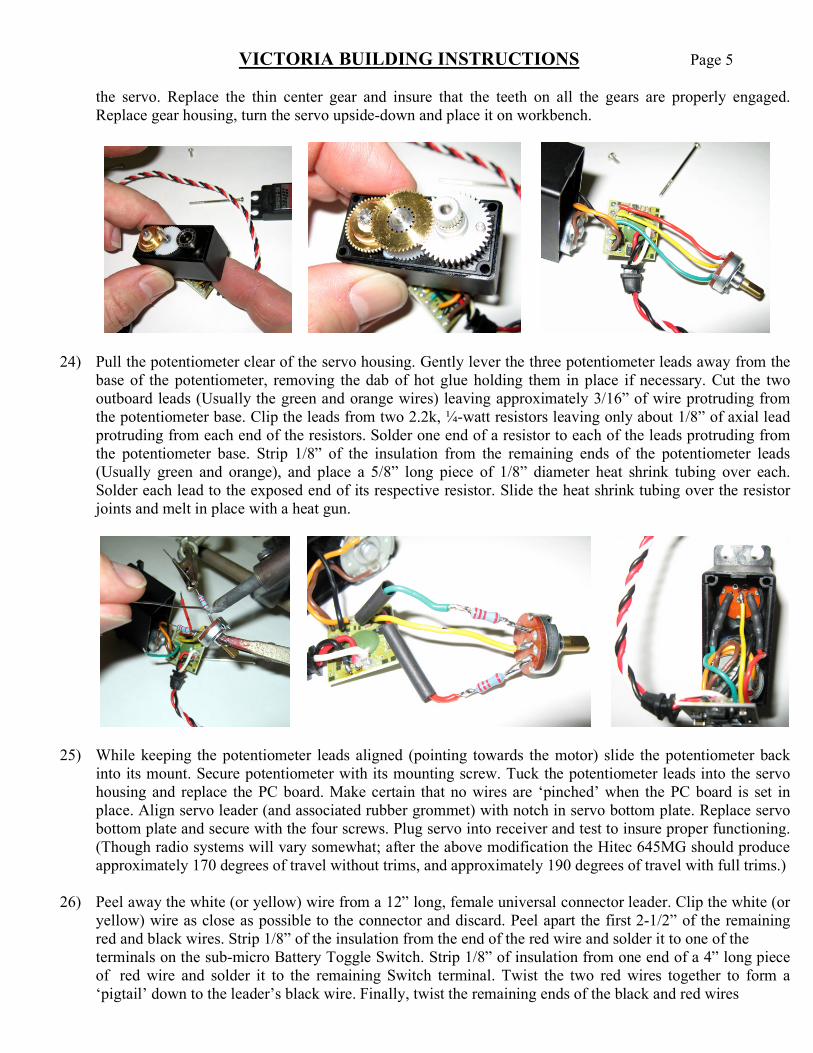
VICTORIA BUILDING INSTRUCTIONS Page 5 the servo. Replace the thin center gear and insure that the teeth on all the gears are properly engaged.
Replace gear housing, turn the servo upside-down and place it on workbench.
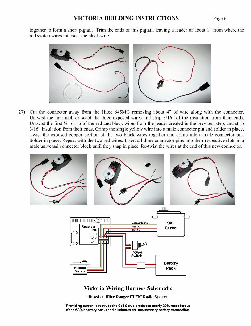
24) Pull the potentiometer clear of the servo housing. Gently lever the three potentiometer leads away from the
base of the potentiometer, removing the dab of hot glue holding them in place if necessary. Cut the two outboard leads (Usually the green and orange wires) leaving approximately 3/16” of wire protruding from the potentiometer base. Clip the leads from two 2.2k, ¼-watt resistors leaving only about 1/8” of axial lead protruding from each end of the resistors. Solder one end of a resistor to each of the leads protruding from the potentiometer base. Strip 1/8” of the insulation from the remaining ends of the potentiometer leads (Usually green and orange), and place a 5/8” long piece of 1/8” diameter heat shrink tubing over each. Solder each lead to the exposed end of its respective resistor. Slide the heat shrink tubing over the resistor joints and melt in place with a heat gun.
25) While keeping the potentiometer leads aligned (pointing towards the motor) slide the potentiometer back into its mount. Secure potentiometer with its mounting screw. Tuck the potentiometer leads into the servo housing and replace the PC board. Make certain that no wires are ‘pinched’ when the PC board is set in place. Align servo leader (and associated rubber grommet) with notch in servo bottom plate. Replace servo bottom plate and secure with the four screws. Plug servo into receiver and test to insure proper functioning. (Though radio systems will vary somewhat; after the above modification the Hitec 645MG should produce approximately 170 degrees of travel without trims, and approximately 190 degrees of travel with full trims.)
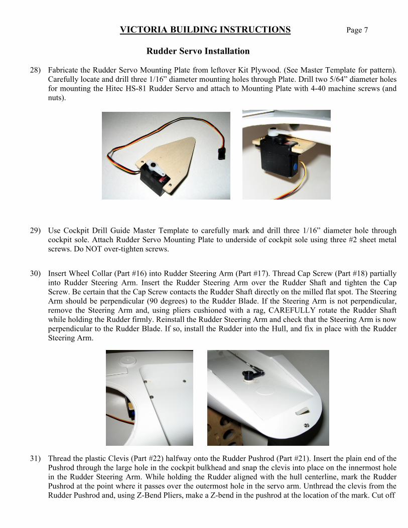
26) Peel away the white (or yellow) wire from a 12” long, female universal connector leader. Clip the white (or
yellow) wire as close as possible to the connector and discard. Peel apart the first 2-1/2” of the remaining red and black wires. Strip 1/8” of the insulation from the end of the red wire and solder it to one of the
terminals on the sub-micro Battery Toggle Switch. Strip 1/8” of insulation from one end of a 4” long piece of red wire and solder it to the remaining Switch terminal. Twist the two red wires together to form a ‘pigtail’ down to the leader’s black wire. Finally, twist the remaining ends of the black and red wires
VICTORIA BUILDING INSTRUCTIONS Page 6 together to form a short pigtail. Trim the ends of this pigtail, leaving a leader of about 1” from where the
red switch wires intersect the black wire.
27) Cut the connector away from the Hitec 645MG removing about 4” of wire along with the connector. Untwist the first inch or so of the three exposed wires and strip 3/16” of the insulation from their ends. Untwist the first ½” or so of the red and black wires from the leader created in the previous step, and strip 3/16” insulation from their ends. Crimp the single yellow wire into a male connector pin and solder in place. Twist the exposed copper portion of the two black wires together and crimp into a male connector pin. Solder in place. Repeat with the two red wires. Insert all three connector pins into their respective slots in a male universal connector block until they snap in place. Re-twist the wires at the end of this new connector.
VICTORIA BUILDING INSTRUCTIONS Page 7
Rudder Servo Installation
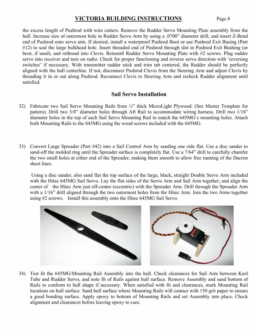
28) Fabricate the Rudder Servo Mounting Plate from leftover Kit Plywood. (See Master Template for pattern). Carefully locate and drill three 1/16” diameter mounting holes through Plate. Drill two 5/64” diameter holes for mounting the Hitec HS-81 Rudder Servo and attach to Mounting Plate with 4-40 machine screws (and nuts).
29) Use Cockpit Drill Guide Master Template to carefully mark and drill three 1/16” diameter hole through cockpit sole. Attach Rudder Servo Mounting Plate to underside of cockpit sole using three #2 sheet metal screws. Do NOT over-tighten screws.
30) Insert Wheel Collar (Part #16) into Rudder Steering Arm (Part #17). Thread Cap Screw (Part #18) partially
into Rudder Steering Arm. Insert the Rudder Steering Arm over the Rudder Shaft and tighten the Cap Screw. Be certain that the Cap Screw contacts the Rudder Shaft directly on the milled flat spot. The Steering Arm should be perpendicular (90 degrees) to the Rudder Blade. If the Steering Arm is not perpendicular, remove the Steering Arm and, using pliers cushioned with a rag, CAREFULLY rotate the Rudder Shaft while holding the Rudder firmly. Reinstall the Rudder Steering Arm and check that the Steering Arm is now perpendicular to the Rudder Blade. If so, install the Rudder into the Hull, and fix in place with the Rudder Steering Arm.
31) Thread the plastic Clevis (Part #22) halfway onto the Rudder Pushrod (Part #21). Insert the plain end of the
Pushrod through the large hole in the cockpit bulkhead and snap the clevis into place on the innermost hole in the Rudder Steering Arm. While holding the Rudder aligned with the hull centerline, mark the Rudder Pushrod at the point where it passes over the outermost hole in the servo arm. Unthread the clevis from the Rudder Pushrod and, using Z-Bend Pliers, make a Z-bend in the pushrod at the location of the mark. Cut off
VICTORIA BUILDING INSTRUCTIONS Page 8 the excess length of Pushrod with wire cutters. Remove the Rudder Servo Mounting Plate assembly from the hull. Increase size of outermost hole in Rudder Servo Arm by using a .0700” diameter drill, and insert Z-Bend end of Pushrod onto servo arm. If desired, install a waterproof Pushrod Boot or use Pushrod Exit Busing (Part #12) to seal the large bulkhead hole. Insert threaded end of Pushrod through slot in Pushrod Exit Bushing (or boot, if used), and rethread into Clevis. Reinstall Rudder Servo Mounting Plate with #2 screws. Plug rudder servo into receiver and turn on radio. Check for proper functioning and reverse servo direction with ‘reversing switches’ if necessary. With transmitter rudder stick and trim tab centered, the Rudder should be perfectly aligned with the hull centerline. If not, disconnect Pushrod Clevis from the Steering Arm and adjust Clevis by threading it in or out along Pushrod. Reconnect Clevis to Steering Arm and recheck Rudder alignment until satisfied.
Sail Servo Installation
32) Fabricate two Sail Servo Mounting Rails from ¼” thick MicroLight Plywood. (See Master Template for
pattern). Drill two 3/8” diameter holes through Aft Rail to accommodate wiring harness. Drill two 1/16” diameter holes in the top of each Sail Servo Mounting Rail to match the 645MG’s mounting holes. Attach both Mounting Rails to the 645MG using the wood screws included with the 645MG.
33) Convert Large Spreader (Part #42) into a Sail Control Arm by sanding one side flat. Use a disc sander to
sand-off the molded ring until the Spreader surface is completely flat. Use a 7/64” drill to carefully chamfer the two small holes at either end of the Spreader, making them smooth to allow free running of the Dacron sheet lines. Using a disc sander, also sand flat the top surface of the large, black, straight Double Servo Arm included with the Hitec 645MG Sail Servo. Lay the flat sides of the Servo Arm and Sail Arm together, and align the center of the Hitec Arm just off-center (eccentric) with the Spreader Arm. Drill through the Spreader Arm with a 1/16” drill aligned through the two outermost holes from the Hitec Arm. Join the two Arms together using #2 screws. Install this assembly onto the Hitec 645MG Sail Servo.
34) Test fit the 645MG/Mounting Rail Assembly into the hull. Check clearances for Sail Arm between Keel
Tube and Rudder Servo, and note fit of Rails against hull surface. Remove Assembly and sand bottom of Rails to conform to hull shape if necessary. When satisfied with fit and clearances, mark Mounting Rail locations on hull surface. Sand hull surface where Mounting Rails will contact with 150 grit paper to ensure a good bonding surface. Apply epoxy to bottom of Mounting Rails and set Assembly into place. Check alignment and clearances before leaving epoxy to cure.
VICTORIA BUILDING INSTRUCTIONS Page 9
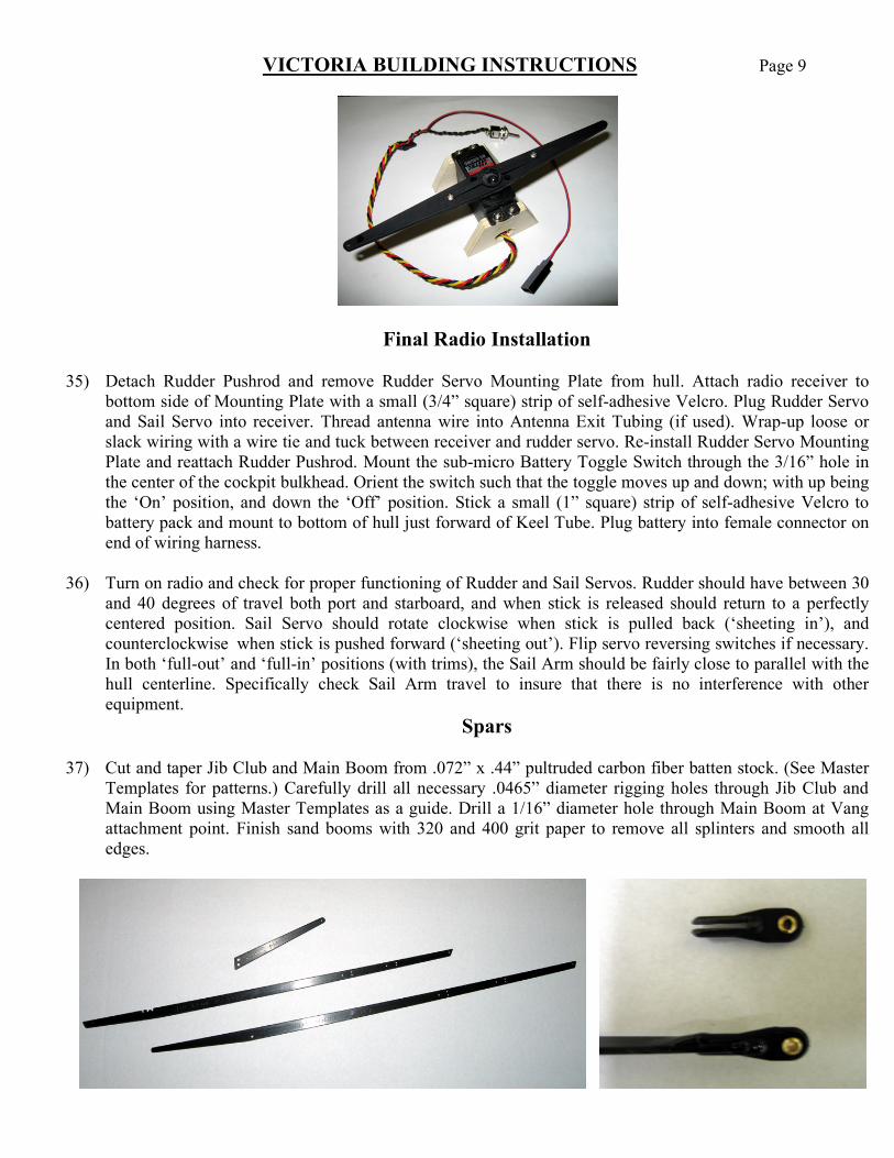
Final Radio Installation
35) Detach Rudder Pushrod and remove Rudder Servo Mounting Plate from hull. Attach radio receiver to bottom side of Mounting Plate with a small (3/4” square) strip of self-adhesive Velcro. Plug Rudder Servo and Sail Servo into receiver. Thread antenna wire into Antenna Exit Tubing (if used). Wrap-up loose or slack wiring with a wire tie and tuck between receiver and rudder servo. Re-install Rudder Servo Mounting Plate and reattach Rudder Pushrod. Mount the sub-micro Battery Toggle Switch through the 3/16” hole in the center of the cockpit bulkhead. Orient the switch such that the toggle moves up and down; with up being the ‘On’ position, and down the ‘Off’ position. Stick a small (1” square) strip of self-adhesive Velcro to battery pack and mount to bottom of hull just forward of Keel Tube. Plug battery into female connector on end of wiring harness.
36) Turn on radio and check for proper functioning of Rudder and Sail Servos. Rudder should have between 30
and 40 degrees of travel both port and starboard, and when stick is released should return to a perfectly centered position. Sail Servo should rotate clockwise when stick is pulled back (‘sheeting in’), and counterclockwise when stick is pushed forward (‘sheeting out’). Flip servo reversing switches if necessary. In both ‘full-out’ and ‘full-in’ positions (with trims), the Sail Arm should be fairly close to parallel with the hull centerline. Specifically check Sail Arm travel to insure that there is no interference with other equipment.
Spars
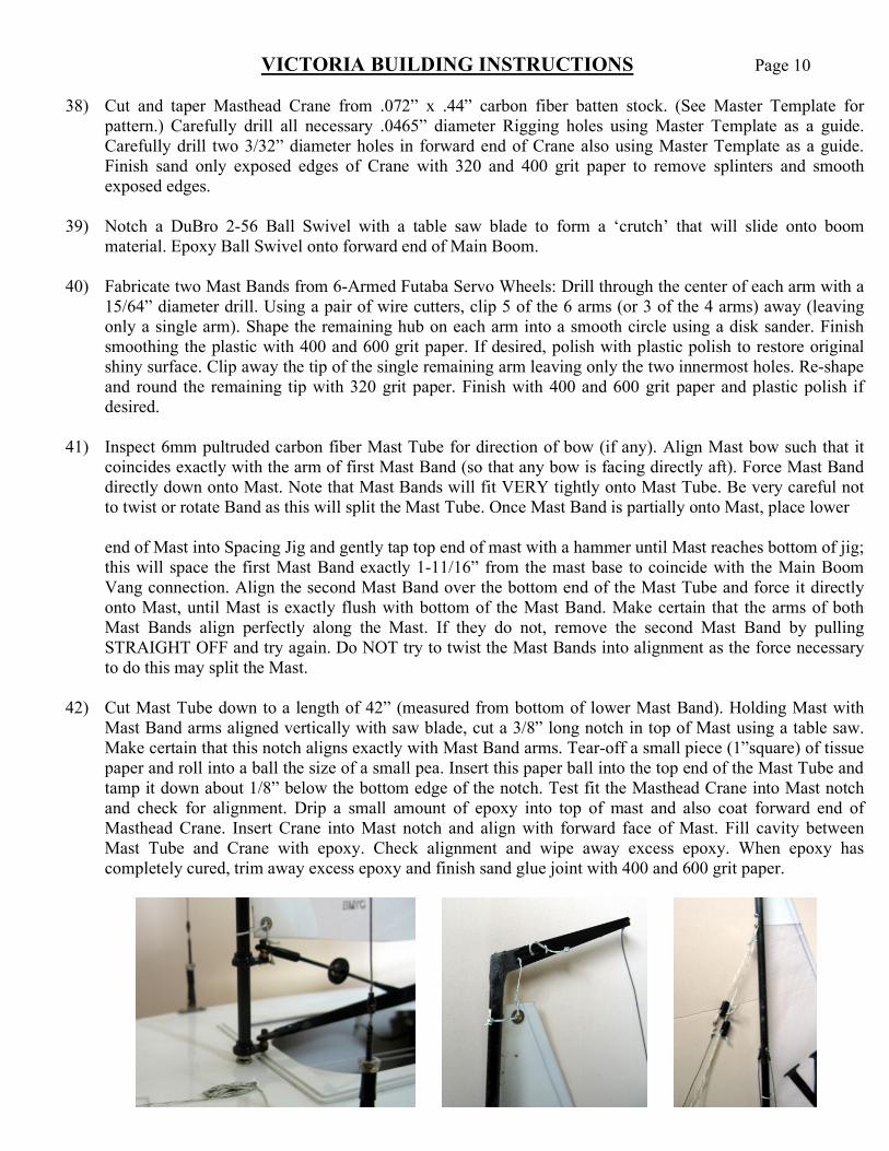
37) Cut and taper Jib Club and Main Boom from .072” x .44” pultruded carbon fiber batten stock. (See Master Templates for patterns.) Carefully drill all necessary .0465” diameter rigging holes through Jib Club and Main Boom using Master Templates as a guide. Drill a 1/16” diameter hole through Main Boom at Vang attachment point. Finish sand booms with 320 and 400 grit paper to remove all splinters and smooth all edges.
VICTORIA BUILDING INSTRUCTIONS Page 10 38) Cut and taper Masthead Crane from .072” x .44” carbon fiber batten stock. (See Master Template for
pattern.) Carefully drill all necessary .0465” diameter Rigging holes using Master Template as a guide. Carefully drill two 3/32” diameter holes in forward end of Crane also using Master Template as a guide. Finish sand only exposed edges of Crane with 320 and 400 grit paper to remove splinters and smooth exposed edges.
39) Notch a DuBro 2-56 Ball Swivel with a table saw blade to form a ‘crutch’ that will slide onto boom
material. Epoxy Ball Swivel onto forward end of Main Boom. 40) Fabricate two Mast Bands from 6-Armed Futaba Servo Wheels: Drill through the center of each arm with a
15/64” diameter drill. Using a pair of wire cutters, clip 5 of the 6 arms (or 3 of the 4 arms) away (leaving only a single arm). Shape the remaining hub on each arm into a smooth circle using a disk sander. Finish smoothing the plastic with 400 and 600 grit paper. If desired, polish with plastic polish to restore original shiny surface. Clip away the tip of the single remaining arm leaving only the two innermost holes. Re-shape and round the remaining tip with 320 grit paper. Finish with 400 and 600 grit paper and plastic polish if desired.
41) Inspect 6mm pultruded carbon fiber Mast Tube for direction of bow (if any). Align Mast bow such that it
coincides exactly with the arm of first Mast Band (so that any bow is facing directly aft). Force Mast Band directly down onto Mast. Note that Mast Bands will fit VERY tightly onto Mast Tube. Be very careful not to twist or rotate Band as this will split the Mast Tube. Once Mast Band is partially onto Mast, place lower
end of Mast into Spacing Jig and gently tap top end of mast with a hammer until Mast reaches bottom of jig;
this will space the first Mast Band exactly 1-11/16” from the mast base to coincide with the Main Boom Vang connection. Align the second Mast Band over the bottom end of the Mast Tube and force it directly onto Mast, until Mast is exactly flush with bottom of the Mast Band. Make certain that the arms of both Mast Bands align perfectly along the Mast. If they do not, remove the second Mast Band by pulling STRAIGHT OFF and try again. Do NOT try to twist the Mast Bands into alignment as the force necessary to do this may split the Mast.
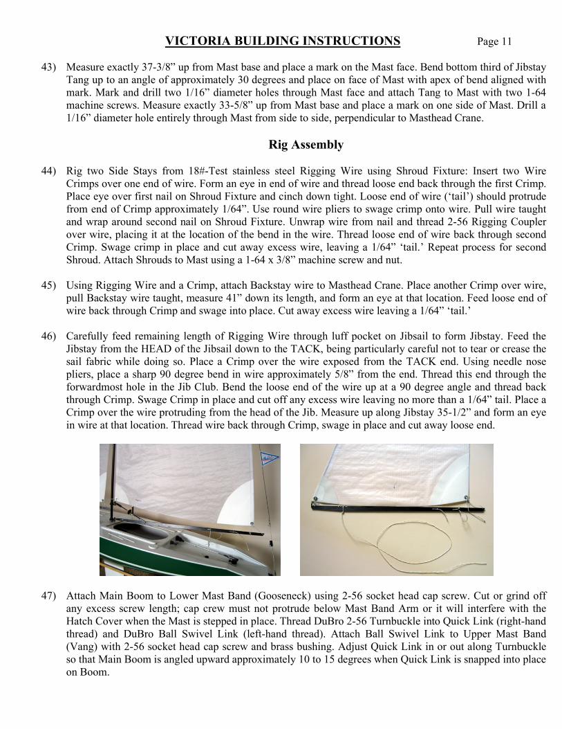
42) Cut Mast Tube down to a length of 42” (measured from bottom of lower Mast Band). Holding Mast with
Mast Band arms aligned vertically with saw blade, cut a 3/8” long notch in top of Mast using a table saw. Make certain that this notch aligns exactly with Mast Band arms. Tear-off a small piece (1”square) of tissue paper and roll into a ball the size of a small pea. Insert this paper ball into the top end of the Mast Tube and tamp it down about 1/8” below the bottom edge of the notch. Test fit the Masthead Crane into Mast notch and check for alignment. Drip a small amount of epoxy into top of mast and also coat forward end of Masthead Crane. Insert Crane into Mast notch and align with forward face of Mast. Fill cavity between Mast Tube and Crane with epoxy. Check alignment and wipe away excess epoxy. When epoxy has completely cured, trim away excess epoxy and finish sand glue joint with 400 and 600 grit paper.
VICTORIA BUILDING INSTRUCTIONS Page 11
43) Measure exactly 37-3/8” up from Mast base and place a mark on the Mast face. Bend bottom third of Jibstay Tang up to an angle of approximately 30 degrees and place on face of Mast with apex of bend aligned with mark. Mark and drill two 1/16” diameter holes through Mast face and attach Tang to Mast with two 1-64 machine screws. Measure exactly 33-5/8” up from Mast base and place a mark on one side of Mast. Drill a 1/16” diameter hole entirely through Mast from side to side, perpendicular to Masthead Crane.
Rig Assembly
44) Rig two Side Stays from 18#-Test stainless steel Rigging Wire using Shroud Fixture: Insert two Wire Crimps over one end of wire. Form an eye in end of wire and thread loose end back through the first Crimp. Place eye over first nail on Shroud Fixture and cinch down tight. Loose end of wire (‘tail’) should protrude from end of Crimp approximately 1/64”. Use round wire pliers to swage crimp onto wire. Pull wire taught and wrap around second nail on Shroud Fixture. Unwrap wire from nail and thread 2-56 Rigging Coupler over wire, placing it at the location of the bend in the wire. Thread loose end of wire back through second Crimp. Swage crimp in place and cut away excess wire, leaving a 1/64” ‘tail.’ Repeat process for second Shroud. Attach Shrouds to Mast using a 1-64 x 3/8” machine screw and nut.
45) Using Rigging Wire and a Crimp, attach Backstay wire to Masthead Crane. Place another Crimp over wire,
pull Backstay wire taught, measure 41” down its length, and form an eye at that location. Feed loose end of wire back through Crimp and swage into place. Cut away excess wire leaving a 1/64” ‘tail.’
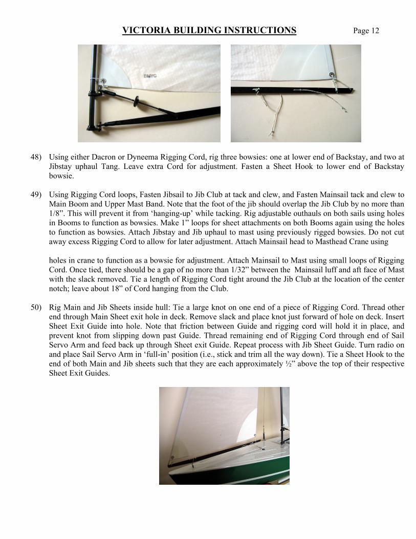
46) Carefully feed remaining length of Rigging Wire through luff pocket on Jibsail to form Jibstay. Feed the
Jibstay from the HEAD of the Jibsail down to the TACK, being particularly careful not to tear or crease the sail fabric while doing so. Place a Crimp over the wire exposed from the TACK end. Using needle nose pliers, place a sharp 90 degree bend in wire approximately 5/8” from the end. Thread this end through the forwardmost hole in the Jib Club. Bend the loose end of the wire up at a 90 degree angle and thread back through Crimp. Swage Crimp in place and cut off any excess wire leaving no more than a 1/64” tail. Place a Crimp over the wire protruding from the head of the Jib. Measure up along Jibstay 35-1/2” and form an eye in wire at that location. Thread wire back through Crimp, swage in place and cut away loose end.
47) Attach Main Boom to Lower Mast Band (Gooseneck) using 2-56 socket head cap screw. Cut or grind off any excess screw length; cap crew must not protrude below Mast Band Arm or it will interfere with the Hatch Cover when the Mast is stepped in place. Thread DuBro 2-56 Turnbuckle into Quick Link (right-hand thread) and DuBro Ball Swivel Link (left-hand thread). Attach Ball Swivel Link to Upper Mast Band (Vang) with 2-56 socket head cap screw and brass bushing. Adjust Quick Link in or out along Turnbuckle so that Main Boom is angled upward approximately 10 to 15 degrees when Quick Link is snapped into place on Boom.
VICTORIA BUILDING INSTRUCTIONS Page 12
48) Using either Dacron or Dyneema Rigging Cord, rig three bowsies: one at lower end of Backstay, and two at Jibstay uphaul Tang. Leave extra Cord for adjustment. Fasten a Sheet Hook to lower end of Backstay bowsie.
49) Using Rigging Cord loops, Fasten Jibsail to Jib Club at tack and clew, and Fasten Mainsail tack and clew to
Main Boom and Upper Mast Band. Note that the foot of the jib should overlap the Jib Club by no more than 1/8”. This will prevent it from ‘hanging-up’ while tacking. Rig adjustable outhauls on both sails using holes in Booms to function as bowsies. Make 1” loops for sheet attachments on both Booms again using the holes to function as bowsies. Attach Jibstay and Jib uphaul to mast using previously rigged bowsies. Do not cut away excess Rigging Cord to allow for later adjustment. Attach Mainsail head to Masthead Crane using
holes in crane to function as a bowsie for adjustment. Attach Mainsail to Mast using small loops of Rigging
Cord. Once tied, there should be a gap of no more than 1/32” between the Mainsail luff and aft face of Mast with the slack removed. Tie a length of Rigging Cord tight around the Jib Club at the location of the center notch; leave about 18” of Cord hanging from the Club.
50) Rig Main and Jib Sheets inside hull: Tie a large knot on one end of a piece of Rigging Cord. Thread other end through Main Sheet exit hole in deck. Remove slack and place knot just forward of hole on deck. Insert Sheet Exit Guide into hole. Note that friction between Guide and rigging cord will hold it in place, and prevent knot from slipping down past Guide. Thread remaining end of Rigging Cord through end of Sail Servo Arm and feed back up through Sheet exit Guide. Repeat process with Jib Sheet Guide. Turn radio on and place Sail Servo Arm in ‘full-in’ position (i.e., stick and trim all the way down). Tie a Sheet Hook to the end of both Main and Jib sheets such that they are each approximately ½” above the top of their respective Sheet Exit Guides.
VICTORIA BUILDING INSTRUCTIONS Page 13
Final Assembly & Testing
51) Place hull in boat stand. Lift rig and place Mast over top of Keel Bolt. Thread Rigging Cord from Jib Club through jibstay eyebolt, pull snug and fasten to cleat near base of Mast. Snap both Side Stay Quick Links
into port and starboard Chain Plates. Snap Backstay Sheet Hook into eyebolt on transom. Adjust Jibstay uphaul bowsies until Mast is raked almost vertically. Tighten backstay bowsie until Jibstay is slightly snug. Detach and adjust port and starboard Side Stay Quick Links until Mast is vertical and stays are slightly snug. Attach Jib and Main Sheets to Cord loops on Booms.
52) Remove boat from stand and place on side. Turn on radio and check for proper functioning of Rudder and
Sails. Sheets should run smoothly through Sail Servo Arm and Sheet Exit Guides. Watch for excess friction or possible snagging on internal equipment. Check Sails for maximum travel; Jib and Main Booms should travel from near centerline (‘full-in’ with trim) to 90 degrees to hull centerline (‘full-out’ with trim).
53) Check rig for final alignment (i.e., mast rake and perpendicularity, shroud and backstay tensions, sheet
travel, sail clearances with booms and backstay, etc.) Check Main and Jib Sheets for proper trim (see Tuning Manual). When satisfied with adjustments, cut away excess Rigging Cord from bowsies, boom loops, outhauls, and Mainsail uphaul leaving a ‘tail’ of about 1-1/2” for fine adjustment. GO SAILING!!!
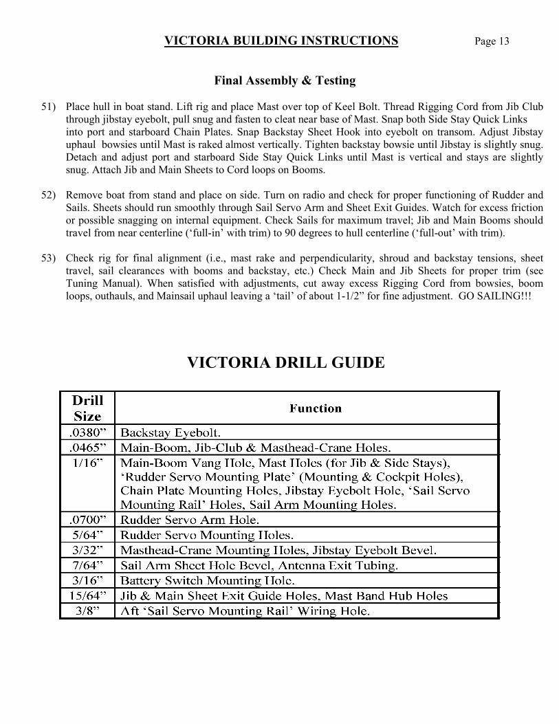
VICTORIA DRILL GUIDE
VICTORIA BUILDING INSTRUCTIONS Page 14
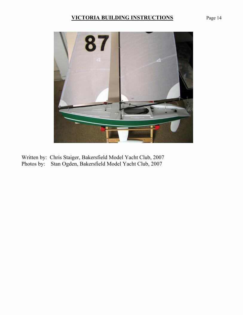
Written by: Chris Staiger, Bakersfield Model Yacht Club, 2007 Photos by: Stan Ogden, Bakersfield Model Yacht Club, 2007