bullseye manual revd en
TRANSCRIPT
8/16/2019 Bullseye Manual RevD En
http://slidepdf.com/reader/full/bullseye-manual-revd-en 1/104
Application manual
BullsEye®
RobotWare 5.0

8/16/2019 Bullseye Manual RevD En
http://slidepdf.com/reader/full/bullseye-manual-revd-en 2/104

8/16/2019 Bullseye Manual RevD En
http://slidepdf.com/reader/full/bullseye-manual-revd-en 3/104
©
C o p y r i g h t 2 0 0 5 - 2 0 0 7 A B B .
A l l r i g h t s r e s e r v e d .
Application manual3HAC024846-001
Revision DBullsEye®
RobotWare 5.0
8/16/2019 Bullseye Manual RevD En
http://slidepdf.com/reader/full/bullseye-manual-revd-en 4/104
© C
o p y r i g h
t 2 0 0 5 - 2 0 0 7 A B B .
A l l r i g h t s r e s e r v e d .
The information in this manual is subject to change without notice and
should not be construed as a commitment by ABB. ABB assumes no re-
sponsibility for any errors that may appear in this manual.
Except as may be expressly stated anywhere in this manual, nothing
herein shall be construed as any kind of guarantee or warranty by ABB
for losses, damages to persons or property, fitness for a specific pur-
pose or the like.
In no event shall ABB be liable for incidental or consequential damagesarising from use of this manual and products described herein.
This manual and parts thereof must not be reproduced or copied without
ABB's written permission, and contents thereof must not be imparted to
a third party nor be used for any unauthorized purpose. Contravention
will be prosecuted.
Additional copies of this manual may be obtained from ABB at its then
current charge.
©Copyright 2005-2007 ABB All rights reserved.
ABB AB
Robotics Products
SE-721 68 Västerås
Sweden
8/16/2019 Bullseye Manual RevD En
http://slidepdf.com/reader/full/bullseye-manual-revd-en 5/104
Table of Content
3HAC024846-001 Revision D
© C
o p y r i g h t 2 0 0 5 - 2 0 0 7 A B B .
A l l r i g h t s r e s e r v e d .
Product Documentation 7
Overview 9
1 Safety 11
1.1 Safety Information . . . . . . . . . . . . . . . . . . . . . . . . . . . . . . . . . . . . . . . . . 11
1.2 Safety signals . . . . . . . . . . . . . . . . . . . . . . . . . . . . . . . . . . . . . . . . . . . . . 12
2 Introduction 13
2.1 Product Overview . . . . . . . . . . . . . . . . . . . . . . . . . . . . . . . . . . . . . . . . . . 13
2.2 Theory of Operation . . . . . . . . . . . . . . . . . . . . . . . . . . . . . . . . . . . . . . . . 15
2.3 New for Version 10 BullsEye® . . . . . . . . . . . . . . . . . . . . . . . . . . . . . . . 17
2.4 Requirements Overview . . . . . . . . . . . . . . . . . . . . . . . . . . . . . . . . . . . . . 18
2.4.1 System Prerequisites . . . . . . . . . . . . . . . . . . . . . . . . . . . . . . . . . . . 18
2.4.2 User’s Qualifications . . . . . . . . . . . . . . . . . . . . . . . . . . . . . . . . . . 18
2.5 Precautions . . . . . . . . . . . . . . . . . . . . . . . . . . . . . . . . . . . . . . . . . . . . . . . 19
3 Installation 21
3.1 Components List . . . . . . . . . . . . . . . . . . . . . . . . . . . . . . . . . . . . . . . . . . 21
3.2 Software installation . . . . . . . . . . . . . . . . . . . . . . . . . . . . . . . . . . . . . . . . 22
3.2.1 Loading BullsEye® software . . . . . . . . . . . . . . . . . . . . . . . . . . . . 22
3.3 Start-up Test . . . . . . . . . . . . . . . . . . . . . . . . . . . . . . . . . . . . . . . . . . . . . . 23
4 Applications Guide 25
4.1 BullsEye® features . . . . . . . . . . . . . . . . . . . . . . . . . . . . . . . . . . . . . . . . 25
4.2 Limitations . . . . . . . . . . . . . . . . . . . . . . . . . . . . . . . . . . . . . . . . . . . . . . . 26
4.2.1 System Complexity . . . . . . . . . . . . . . . . . . . . . . . . . . . . . . . . . . . . 26
4.2.2 Tool Designs . . . . . . . . . . . . . . . . . . . . . . . . . . . . . . . . . . . . . . . . . 26
8/16/2019 Bullseye Manual RevD En
http://slidepdf.com/reader/full/bullseye-manual-revd-en 6/104
Table of Contents
4 3HAC024846-001 Revision D
© C
o p y r i g h t 2 0 0
5 - 2 0 0 7 A B B .
A l l r i g h t s r e s e r v e d .
4.2.3 TCP z-axis inline with mounting surface z-axis not supported. . . 28
4.2.4 BE_Data.sys is a reserved module name. . . . . . . . . . . . . . . . . . . . 285 User’s Guide 29
5.1 Safety . . . . . . . . . . . . . . . . . . . . . . . . . . . . . . . . . . . . . . . . . . . . . . . . . . . 29
5.2 Overview . . . . . . . . . . . . . . . . . . . . . . . . . . . . . . . . . . . . . . . . . . . . . . . . . 30
5.3 Data Storage . . . . . . . . . . . . . . . . . . . . . . . . . . . . . . . . . . . . . . . . . . . . . . 31
5.4 Using BullsEye®. . . . . . . . . . . . . . . . . . . . . . . . . . . . . . . . . . . . . . . . . . . 32
5.4.1 The Global Methods of BullsEye® . . . . . . . . . . . . . . . . . . . . . . . . 33
5.4.2 Set-up a tool. . . . . . . . . . . . . . . . . . . . . . . . . . . . . . . . . . . . . . . . . . 34
5.4.3 Default BullsEye® Data . . . . . . . . . . . . . . . . . . . . . . . . . . . . . . . . 37
5.4.4 Selecting Different BullsEye® Data . . . . . . . . . . . . . . . . . . . . . . . 38
5.4.5 Creating New BullsEye® Data Instances . . . . . . . . . . . . . . . . . . . 41
5.4.6 BullsEye® Data Parameters . . . . . . . . . . . . . . . . . . . . . . . . . . . . . 44
5.4.7 QuickCheck . . . . . . . . . . . . . . . . . . . . . . . . . . . . . . . . . . . . . . . . . . 45
5.5 BullsEye® Status Codes . . . . . . . . . . . . . . . . . . . . . . . . . . . . . . . . . . . . . 47
5.5.1 Error codes . . . . . . . . . . . . . . . . . . . . . . . . . . . . . . . . . . . . . . . . . . 47
5.6 Commonly Asked Questions. . . . . . . . . . . . . . . . . . . . . . . . . . . . . . . . . . 53
5.6.1 How do I configure the digital input signal? . . . . . . . . . . . . . . . . 53
5.6.2 How do I implement multiple tools? . . . . . . . . . . . . . . . . . . . . . . 53
5.6.3 How should robot carriers be configured?. . . . . . . . . . . . . . . . . . . 54
5.6.4 How do I set up BullsEye® when the robot is moved by a track? 55
5.6.5 Can I change my TCP extension without rerunning
the initialization? . . . . . . . . . . . . . . . . . . . . . . . . . . . . . . . . . . . . . 55
5.6.6 Can the BullsEye® yoke be mounted in any orientation? . . . . . . 55
5.6.7 How should robot carriers be configured?. . . . . . . . . . . . . . . . . . . 56
5.6.8 How do I set up a non-ABB supplied IO device? . . . . . . . . . . . . . 58
8/16/2019 Bullseye Manual RevD En
http://slidepdf.com/reader/full/bullseye-manual-revd-en 7/104
Table of Content
3HAC024846-001 Revision D
© C
o p y r i g h t 2 0 0 5 - 2 0 0 7 A B B .
A l l r i g h t s r e s e r v e d .
5.6.9 What is a "convergence error"? . . . . . . . . . . . . . . . . . . . . . . . . . . . 59
5.6.10 How do I setup BullsEye to calibrate a tool like this?. . . . . . . . . 606 Software Reference 63
6.1 Data Types . . . . . . . . . . . . . . . . . . . . . . . . . . . . . . . . . . . . . . . . . . . . . . . 63
6.1.1 be_device, Device data . . . . . . . . . . . . . . . . . . . . . . . . . . . . . . . . . 63
6.1.2 be_scan, Scan data. . . . . . . . . . . . . . . . . . . . . . . . . . . . . . . . . . . . . 66
6.1.3 be_tooldesign, Tool design . . . . . . . . . . . . . . . . . . . . . . . . . . . . . . 69
6.2 Instructions . . . . . . . . . . . . . . . . . . . . . . . . . . . . . . . . . . . . . . . . . . . . . . . 73
6.2.1 BECheckTcp, Bullseye: Check TCP . . . . . . . . . . . . . . . . . . . . . . 73
6.2.2 BEDebugState, Debug State Control. . . . . . . . . . . . . . . . . . . . . . . 77
6.2.3 BERefPointer, Bullseye: Reference Pointer . . . . . . . . . . . . . . . . . 79
6.2.4 BESetupToolJ, Bullseye: Setup Tool Joint Move. . . . . . . . . . . . . 83
6.2.5 BETcpExtend, Bullseye: Extend TCP. . . . . . . . . . . . . . . . . . . . . . 89
6.2.6 BEUpdateTcp, Bullseye: Update TCP . . . . . . . . . . . . . . . . . . . . . 92
6.3 Functions. . . . . . . . . . . . . . . . . . . . . . . . . . . . . . . . . . . . . . . . . . . . . . . . . 97
6.3.1 OffsToolXYZ, Offsets Tool - Cartesian . . . . . . . . . . . . . . . . . . . . 97
6.3.2 OffsToolPolar, Offsets Tool - Cartesian . . . . . . . . . . . . . . . . . . . . 99

8/16/2019 Bullseye Manual RevD En
http://slidepdf.com/reader/full/bullseye-manual-revd-en 8/104
Table of Contents
6 3HAC024846-001 Revision D
© C
o p y r i g h t 2 0 0
5 - 2 0 0 7 A B B .
A l l r i g h t s r e s e r v e d .
8/16/2019 Bullseye Manual RevD En
http://slidepdf.com/reader/full/bullseye-manual-revd-en 9/104
Product Documentatio
3HAC024846-001 Revision D
© C
o p y r i g h t 2 0 0
5 - 2 0 0 6 A B B .
A l l r i g h t s r e s e r v e d .
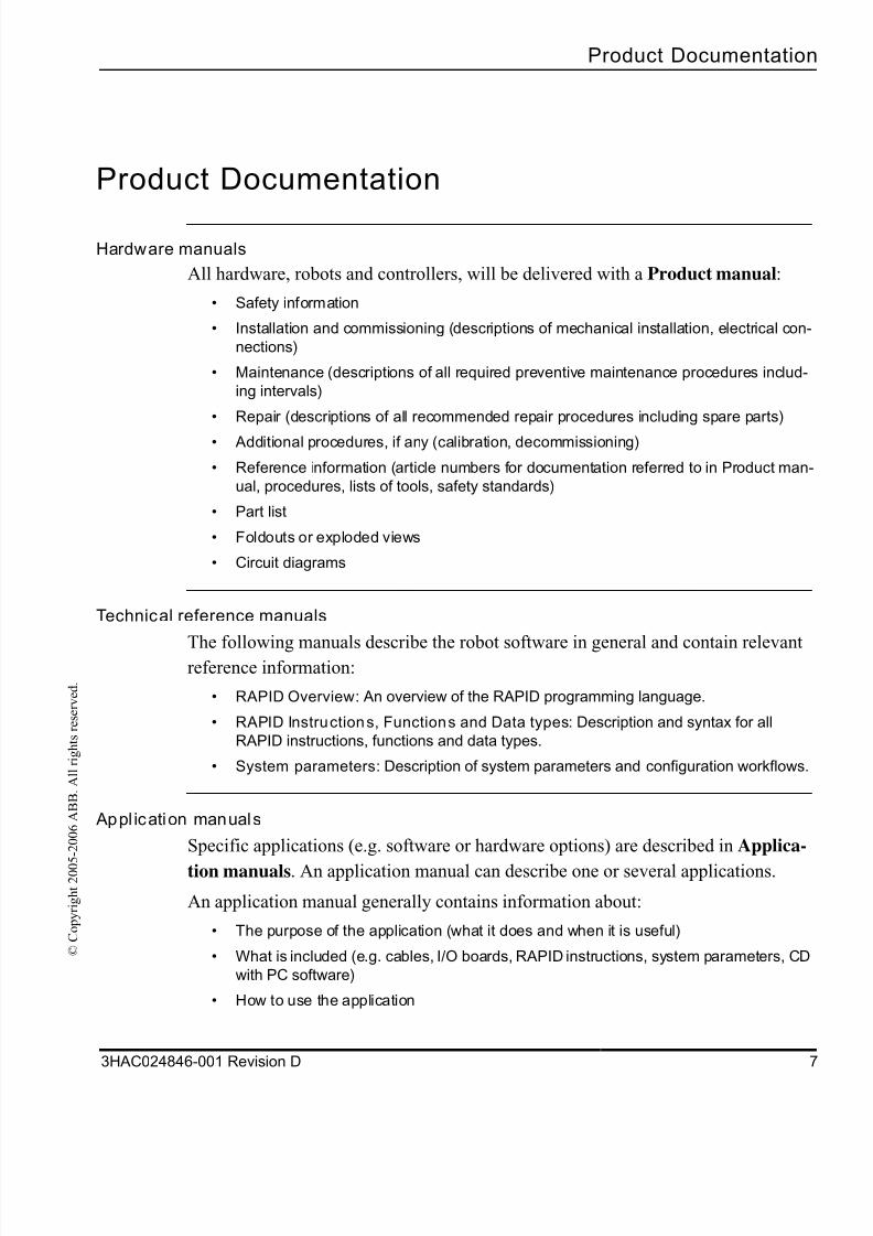
Product Documentation
Hardware manuals
All hardware, robots and controllers, will be delivered with a Product manual:
• Safety information
• Installation and commissioning (descriptions of mechanical installation, electrical con
nections)
• Maintenance (descriptions of all required preventive maintenance procedures includ-
ing intervals)
• Repair (descriptions of all recommended repair procedures including spare parts)
• Additional procedures, if any (calibration, decommissioning)
• Reference information (article numbers for documentation referred to in Product man
ual, procedures, lists of tools, safety standards)
• Part list
• Foldouts or exploded views
• Circuit diagrams
Technical reference manuals
The following manuals describe the robot software in general and contain relevantreference information:
• RAPID Overview: An overview of the RAPID programming language.
• RAPID Instructions, Functions and Data types: Description and syntax for all
RAPID instructions, functions and data types.
• System parameters: Description of system parameters and configuration workflows
Appl ication manuals
Specific applications (e.g. software or hardware options) are described in Applica-
tion manuals. An application manual can describe one or several applications.
An application manual generally contains information about:
• The purpose of the application (what it does and when it is useful)
• What is included (e.g. cables, I/O boards, RAPID instructions, system parameters, CD
with PC software)
• How to use the application
8/16/2019 Bullseye Manual RevD En
http://slidepdf.com/reader/full/bullseye-manual-revd-en 10/104
Product Documentation
8 3HAC024846-001 Revision D
© C
o p y r i g h t 2 0 0 5 - 2 0 0 6 A B B .
A l l r i g h t s r e s e r v e d .
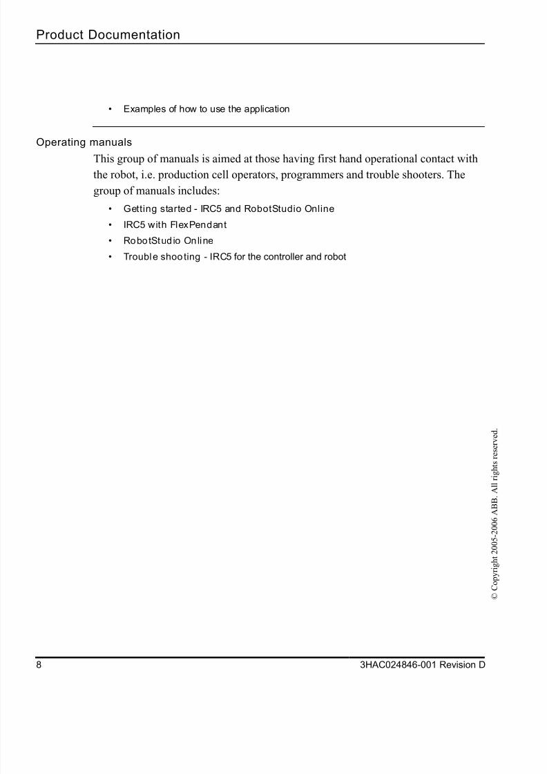
• Examples of how to use the application
Operating manuals
This group of manuals is aimed at those having first hand operational contact with
the robot, i.e. production cell operators, programmers and trouble shooters. The
group of manuals includes:
• Getting started - IRC5 and RobotStudio Online
• IRC5 with FlexPendant
• RobotStudio Online
• Trouble shooting - IRC5 for the controller and robot
8/16/2019 Bullseye Manual RevD En
http://slidepdf.com/reader/full/bullseye-manual-revd-en 11/104
Overview
3HAC024846-001 Revision D
© C
o p y r i g h t 2 0
0 5 - 2 0 0 7 A B B .
A l l r i g h t s r e s e r v e d .
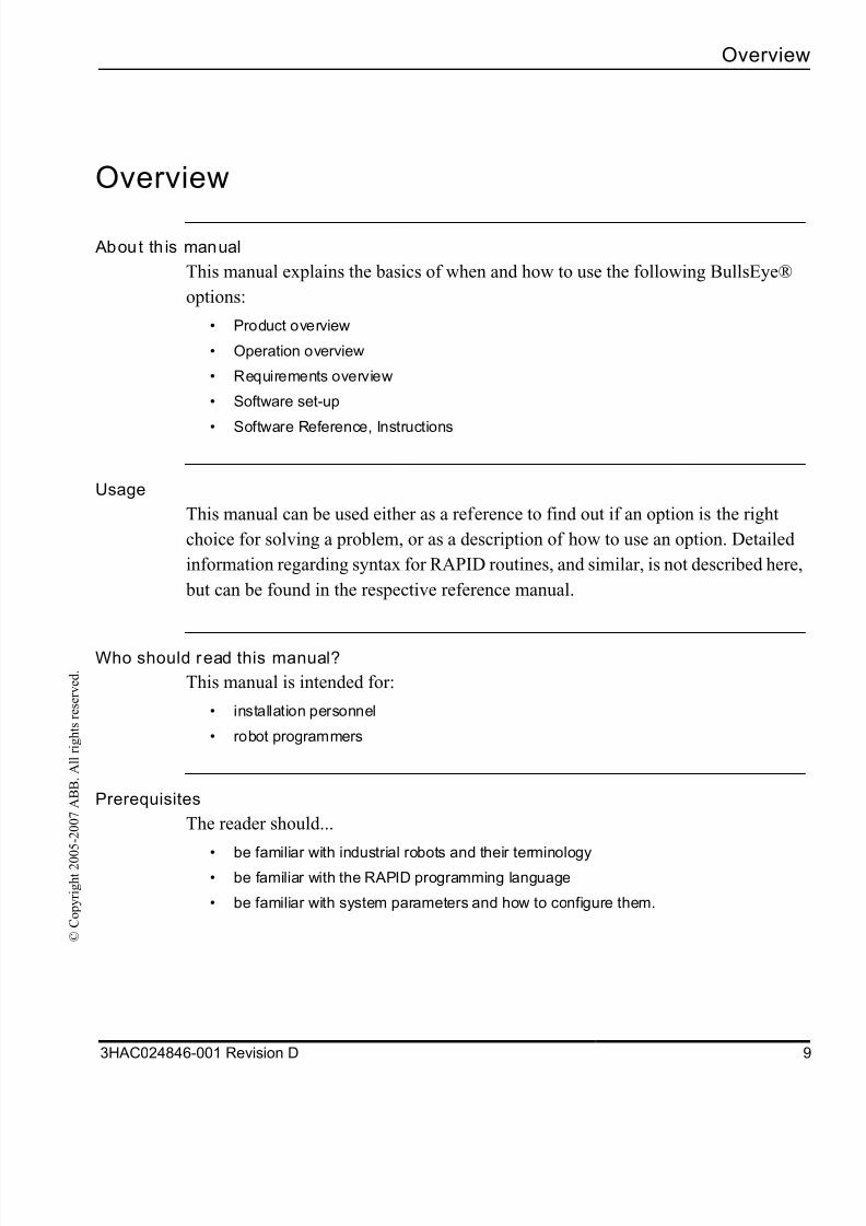
Overview
About th is manual
This manual explains the basics of when and how to use the following BullsEye®
options:
• Product overview
• Operation overview
• Requirements overview
• Software set-up
• Software Reference, Instructions
Usage
This manual can be used either as a reference to find out if an option is the right
choice for solving a problem, or as a description of how to use an option. Detailed
information regarding syntax for RAPID routines, and similar, is not described here
but can be found in the respective reference manual.
Who should read this manual?
This manual is intended for:
• installation personnel
• robot programmers
Prerequisites
The reader should...
• be familiar with industrial robots and their terminology• be familiar with the RAPID programming language
• be familiar with system parameters and how to configure them.
8/16/2019 Bullseye Manual RevD En
http://slidepdf.com/reader/full/bullseye-manual-revd-en 12/104
Overview
10 3HAC024846-001 Revision D
© C
o p y r i g h t 2 0
0 5 - 2 0 0 7 A B B .
A l l r i g h t s r e s e r v e d .
Reference documents
Reference Document Id.
Technical reference manual - RAPID overview 3HAC16580-1
Technical reference manual - RAPID Instructions, Functions
and data types
3HAC16581-1
Operating manual - Getting started, IRC5 and RobotStudio
Online
3HAC027097-001
Operating manual - IRC5 with FlexPendant 3HAC16590-1
Technical reference manual - System parameters 3HAC17076-1
Operating manual - RobotStudio Online 3HAC18236-1
Application manual - Production Manager 3HAC024844-001
8/16/2019 Bullseye Manual RevD En
http://slidepdf.com/reader/full/bullseye-manual-revd-en 13/104
1 Safet
1.1 Safety Informatio
3HAC024846-001 Revision D 1
© C
o p y r i g h t 2 0 0 5 - 2 0 0 7 A B B .
A l l r i g h t s r e s e r v e d .
1 Safety
1.1 Safety Information
Overview
A robot is heavy and extremely powerful regardless of its speed. A pause or long stop
in movement can be followed by a fast hazardous movement. Even if a pattern of
movement is predicted, a change in operation can be triggered by an external signal
resulting in an unexpected movement.
Therefore, it is important that all safety regulations are followed when entering safe
guarded space.
Description
Before beginning work with the robot, make sure you are familiar with the safety
regulations described below.
Reference document
Reference Document Id
Operating manual - IRC5 with FlexPendant 3HAC16590-1
Safety instructions AW System manual, Introduction andSafety.
8/16/2019 Bullseye Manual RevD En
http://slidepdf.com/reader/full/bullseye-manual-revd-en 14/104
1 Safety
1.2 Safety signals
12 3HAC024846-001 Revision D
© C
o p y r i g h t 2 0 0 5 - 2 0 0 7 A B B .
A l l r i g h t s r e s e r v e d .
1.2 Safety signals
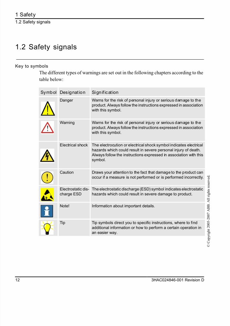
Key to symbols
The different types of warnings are set out in the following chapters according to the
table below:
Symbol Designat ion Sign if icat ion
!
Danger Warns for the risk of personal injury or serious damage to the
product. Always follow the instructions expressed in association
with this symbol.
Warning Warns for the risk of personal injury or serious damage to the
product. Always follow the instructions expressed in association
with this symbol.
Electrical shock The electrocution or electrical shock symbol indicates electrical
hazards which could result in severe personal injury of death.
Always follow the instructions expressed in association with this
symbol.
Caution Draws your attention to the fact that damage to the product canoccur if a measure is not performed or is performed incorrectly.
Electrostatic dis-
charge ESD
The electrostatic discharge (ESD) symbol indicates electrostatic
hazards which could result in severe damage to product.
Note! Information about important details.
Tip Tip symbols direct you to specific instructions, where to find
additional information or how to perform a certain operation inan easier way.
8/16/2019 Bullseye Manual RevD En
http://slidepdf.com/reader/full/bullseye-manual-revd-en 15/104
2 Introductio
2.1 Product Overvie
3HAC024846-001 Revision D 1
© C
o p y r i g h t 2 0 0 5 - 2 0 0 7 A B B .
A l l r i g h t s r e s e r v e d .
2 Introduction
BullsEye
®
10 provides completely automated Tool Center Point (TCP) definition forthe IRC5 robot controller.
2.1 Product Overview
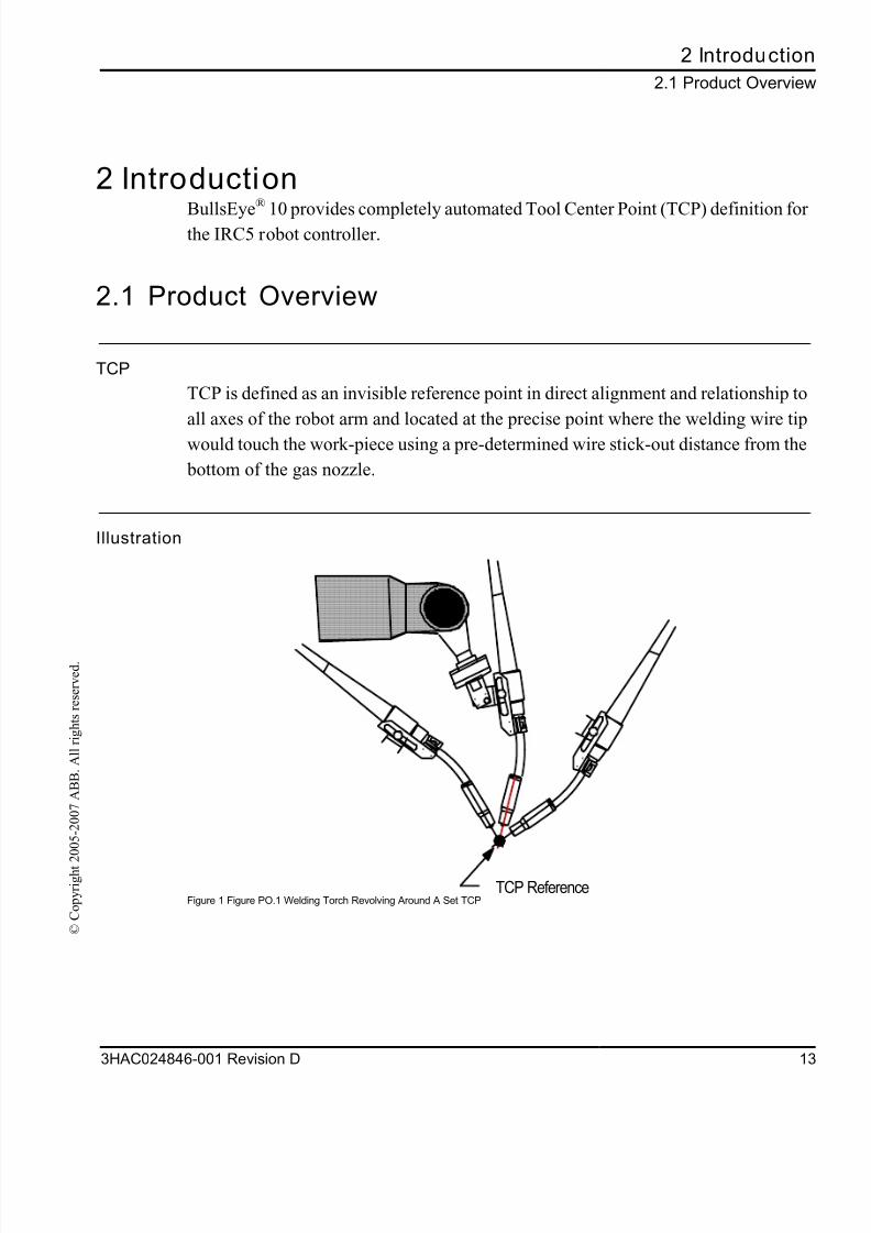
TCP
TCP is defined as an invisible reference point in direct alignment and relationship to
all axes of the robot arm and located at the precise point where the welding wire tip
would touch the work-piece using a pre-determined wire stick-out distance from the
bottom of the gas nozzle.
Illustration
Figure 1 Figure PO.1 Welding Torch Revolving Around A Set TCPTCP Reference

8/16/2019 Bullseye Manual RevD En
http://slidepdf.com/reader/full/bullseye-manual-revd-en 16/104
2 Introduction
2.1 Product Overview
14 3HAC024846-001 Revision D
© C
o p y r i g h t 2 0 0 5 - 2 0 0 7 A B B .
A l l r i g h t s r e s e r v e d .
BullsEye®
BullsEye® 10 introduces support of new tools in addition to MIG welding torch
configurations. Concentric cutting tools may also be used where the stick-out is
defined as the distance from the cutting tip to the part surface. The Applications
Guide in this reference manual describes BullsEye® limitations.
8/16/2019 Bullseye Manual RevD En
http://slidepdf.com/reader/full/bullseye-manual-revd-en 17/104
2 Introductio
2.2 Theory of Operatio
3HAC024846-001 Revision D 1
© C
o p y r i g h t 2 0 0 5 - 2 0 0 7 A B B .
A l l r i g h t s r e s e r v e d .
2.2 Theory of Operation
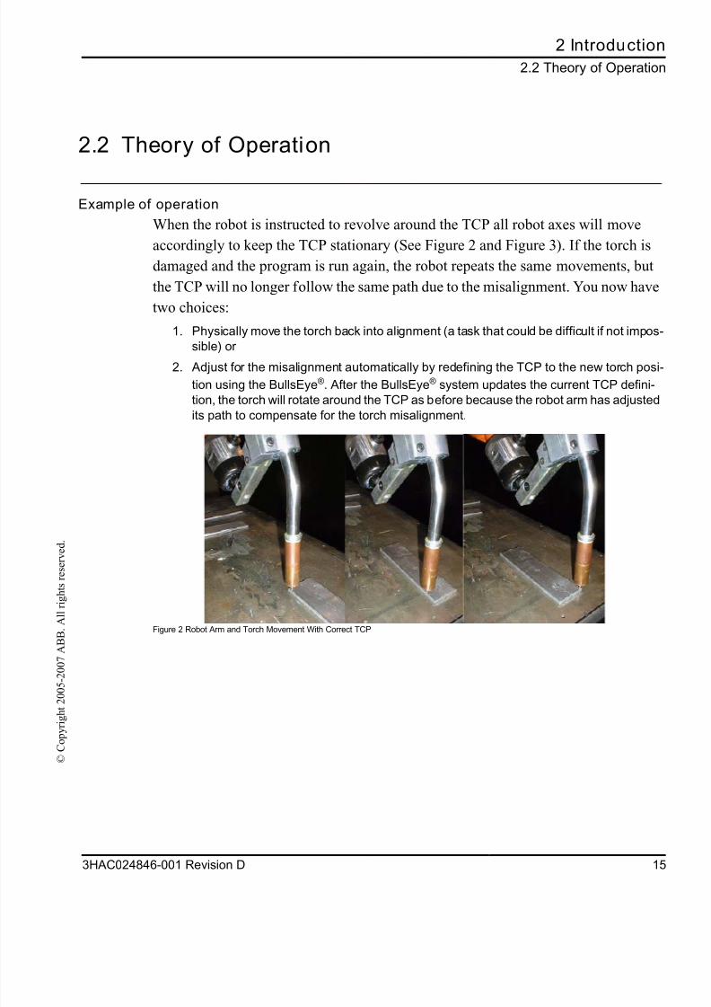
Example of operation
When the robot is instructed to revolve around the TCP all robot axes will move
accordingly to keep the TCP stationary (See Figure 2 and Figure 3). If the torch is
damaged and the program is run again, the robot repeats the same movements, but
the TCP will no longer follow the same path due to the misalignment. You now have
two choices:
1. Physically move the torch back into alignment (a task that could be difficult if not impos
sible) or 2. Adjust for the misalignment automatically by redefining the TCP to the new torch pos
tion using the BullsEye®. After the BullsEye® system updates the current TCP defini-
tion, the torch will rotate around the TCP as before because the robot arm has adjusted
its path to compensate for the torch misalignment.
Figure 2 Robot Arm and Torch Movement With Correct TCP
8/16/2019 Bullseye Manual RevD En
http://slidepdf.com/reader/full/bullseye-manual-revd-en 18/104
2 Introduction
2.2 Theory of Operation
16 3HAC024846-001 Revision D
© C
o p y r i g h t 2 0 0 5 - 2 0 0 7 A B B .
A l l r i g h t s r e s e r v e d .
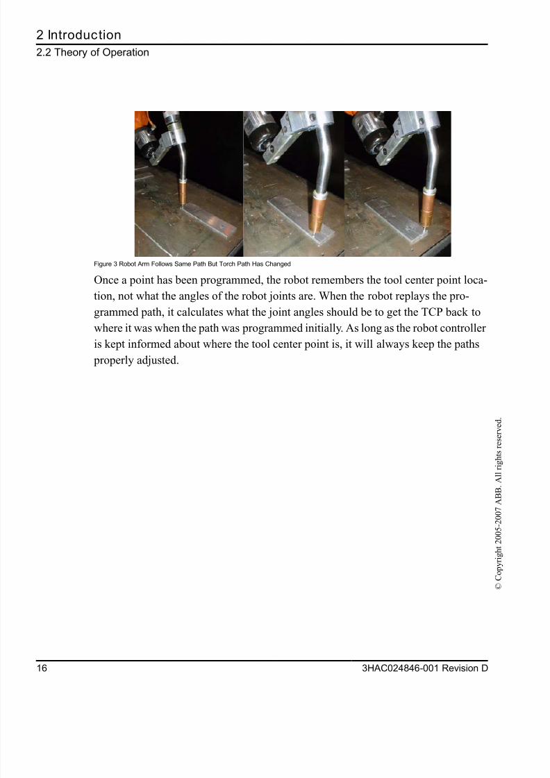
Figure 3 Robot Arm Follows Same Path But Torch Path Has Changed
Once a point has been programmed, the robot remembers the tool center point loca-
tion, not what the angles of the robot joints are. When the robot replays the pro-
grammed path, it calculates what the joint angles should be to get the TCP back to
where it was when the path was programmed initially. As long as the robot controller
is kept informed about where the tool center point is, it will always keep the paths
properly adjusted.

8/16/2019 Bullseye Manual RevD En
http://slidepdf.com/reader/full/bullseye-manual-revd-en 19/104
2 Introductio
2.3 New for Version 10 BullsEye
3HAC024846-001 Revision D 1
© C
o p y r i g h t 2 0 0 5 - 2 0 0 7 A B B .
A l l r i g h t s r e s e r v e d .
2.3 New for Version 10 BullsEye®
1. Full MultiMove compatibility.
2. Improved joint limit checking to detect out-of-reach errors early in the setup.
3. Fully integrated with RobotWare delivery.
8/16/2019 Bullseye Manual RevD En
http://slidepdf.com/reader/full/bullseye-manual-revd-en 20/104
2 Introduction
2.4 Requirements Overview
18 3HAC024846-001 Revision D
© C
o p y r i g h t 2 0 0 5 - 2 0 0 7 A B B .
A l l r i g h t s r e s e r v e d .
2.4 Requirements Overview
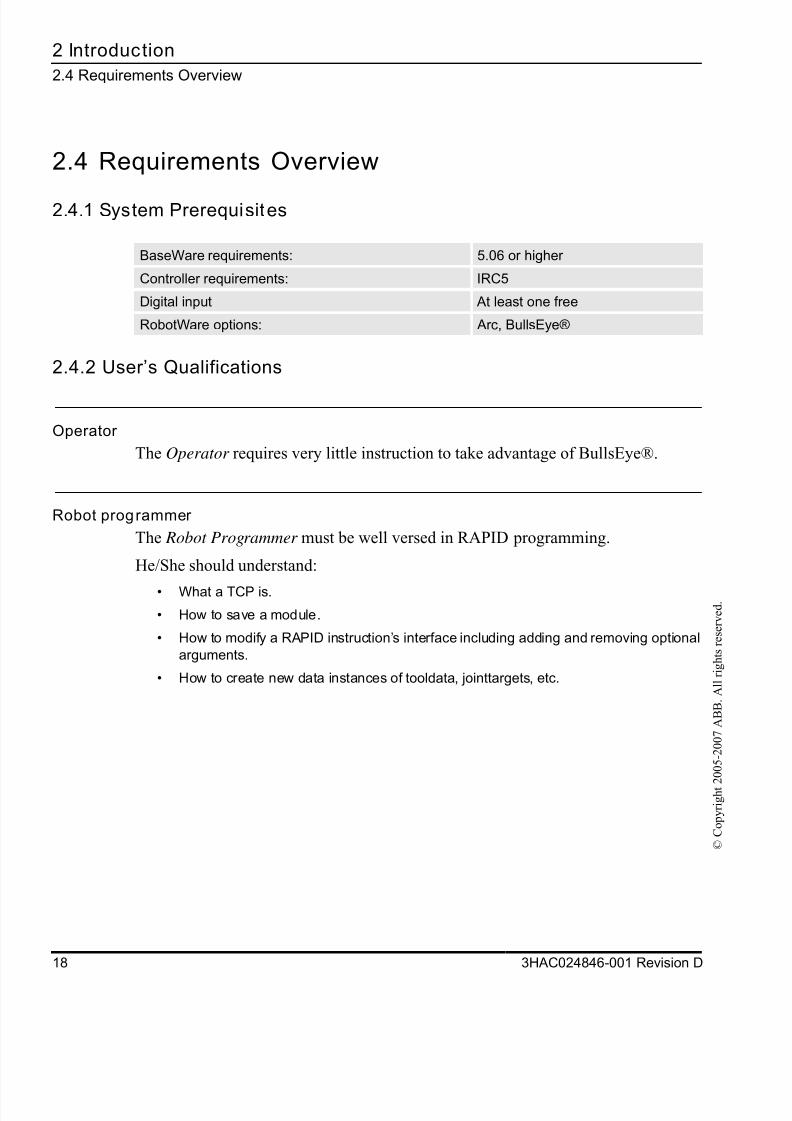
2.4.1 System Prerequisites
2.4.2 User’s Qualifications
Operator
The Operator requires very little instruction to take advantage of BullsEye®.
Robot programmer
The Robot Programmer must be well versed in RAPID programming.
He/She should understand:
• What a TCP is.
• How to save a module.
• How to modify a RAPID instruction’s interface including adding and removing optional
arguments.
• How to create new data instances of tooldata, jointtargets, etc.
BaseWare requirements: 5.06 or higher
Controller requirements: IRC5
Digital input At least one free
RobotWare options: Arc, BullsEye®
8/16/2019 Bullseye Manual RevD En
http://slidepdf.com/reader/full/bullseye-manual-revd-en 21/104
2 Introductio
2.5 Precaution
3HAC024846-001 Revision D 1
© C
o p y r i g h t 2 0 0 5 - 2 0 0 7 A B B .
A l l r i g h t s r e s e r v e d .
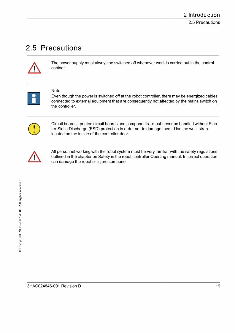
2.5 Precautions
The power supply must always be switched off whenever work is carried out in the control
cabinet
Note:
Even though the power is switched off at the robot controller, there may be energized cables
connected to external equipment that are consequently not affected by the mains switch on
the controller.
Circuit boards - printed circuit boards and components - must never be handled without Elec
tro-Static-Discharge (ESD) protection in order not to damage them. Use the wrist strap
located on the inside of the controller door.
All personnel working with the robot system must be very familiar with the safety regulations
outlined in the chapter on Safety in the robot controller Operting manual. Incorrect operation
can damage the robot or injure someone

8/16/2019 Bullseye Manual RevD En
http://slidepdf.com/reader/full/bullseye-manual-revd-en 22/104
2 Introduction
2.5 Precautions
20 3HAC024846-001 Revision D
© C
o p y r i g h t 2 0 0 5 - 2 0 0 7 A B B .
A l l r i g h t s r e s e r v e d .
8/16/2019 Bullseye Manual RevD En
http://slidepdf.com/reader/full/bullseye-manual-revd-en 23/104
3 Installatio
3.1 Components Li
3HAC024846-001 Revision D 2
© C
o p y r i g h t 2 0 0 5 - 2 0 0 7 A B B .
A l l r i g h t s r e s e r v e d .
3 Installation
3.1 Components List
BullsEye® consis ts of the following components:
• BullsEye® Application Manual. This will be distributed in electronic format, unless a
printed version is purchased.
• BullsEye® scanning device. Typically this will be the standard BullsEye® yoke
described below.• BullsEye® RAPID robot software. Software may be delivered as a separate product
bundled on a CD-ROM with documentation, or as part of cell management software
like GAP and EasyArc.
8/16/2019 Bullseye Manual RevD En
http://slidepdf.com/reader/full/bullseye-manual-revd-en 24/104
3 Installation
3.2 Software installation
22 3HAC024846-001 Revision D
© C
o p y r i g h t 2 0 0 5 - 2 0 0 7 A B B .
A l l r i g h t s r e s e r v e d .
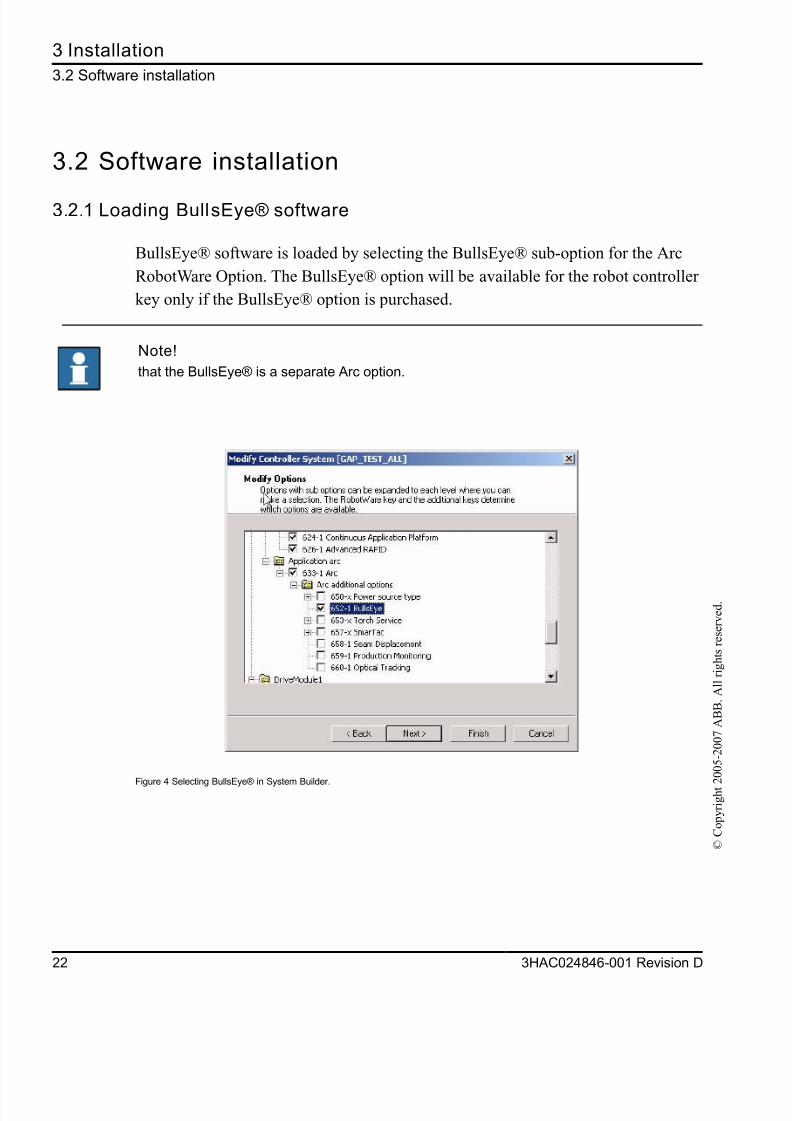
3.2 Software installation
3.2.1 Loading BullsEye® software
BullsEye® software is loaded by selecting the BullsEye® sub-option for the Arc
RobotWare Option. The BullsEye® option will be available for the robot controller
key only if the BullsEye® option is purchased.
Figure 4 Selecting BullsEye® in System Builder.
Note!
that the BullsEye® is a separate Arc option.
8/16/2019 Bullseye Manual RevD En
http://slidepdf.com/reader/full/bullseye-manual-revd-en 25/104
3 Installatio
3.3 Start-up Te
3HAC024846-001 Revision D 2
© C
o p y r i g h t 2 0 0 5 - 2 0 0 7 A B B .
A l l r i g h t s r e s e r v e d .
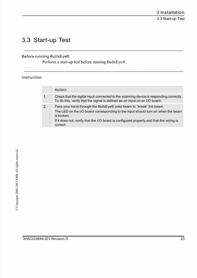
3.3 Start-up Test
Before running Bul lsEye®
Perform a start-up test before running BullsEye®.
Instruction
Action
1. Check that the digital input connected to the scanning device is responding correctly.To do this, verify that the signal is defined as an input on an I/O board.
2. Pass your hand through the BullsEye® yoke beam to “break” the beam.
The LED on the I/O board corresponding to the input should turn on when the beam
is broken.
If it does not, verify that the I/O board is configured properly and that the wiring is
correct.

8/16/2019 Bullseye Manual RevD En
http://slidepdf.com/reader/full/bullseye-manual-revd-en 26/104
3 Installation
3.3 Start-up Test
24 3HAC024846-001 Revision D
© C
o p y r i g h t 2 0 0 5 - 2 0 0 7 A B B .
A l l r i g h t s r e s e r v e d .
8/16/2019 Bullseye Manual RevD En
http://slidepdf.com/reader/full/bullseye-manual-revd-en 27/104
4 Applications Guid
4.1 BullsEye® feature
3HAC024846-001 Revision D 2
© C
o p y r i g h t 2 0 0 5 - 2 0 0 7 A B B .
A l l r i g h t s r e s e r v e d .
4 Applications Guide
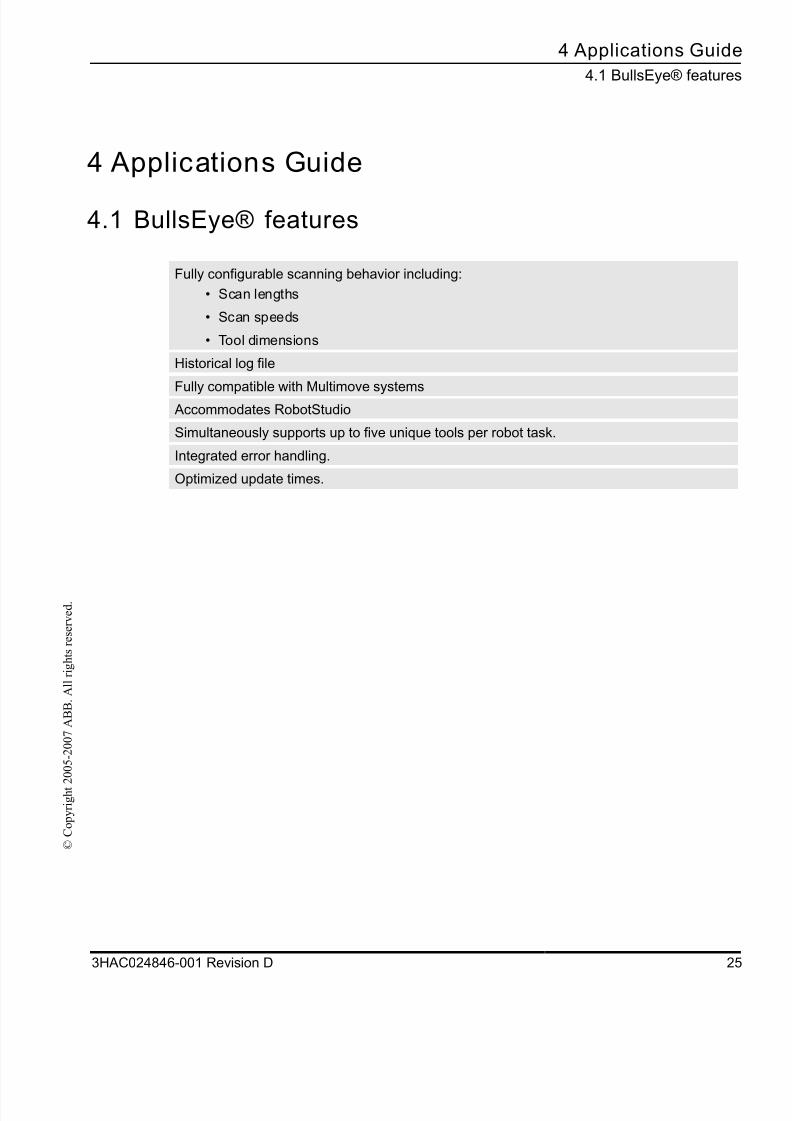
4.1 BullsEye® features
Fully configurable scanning behavior including:
• Scan lengths
• Scan speeds
• Tool dimensions
Historical log file
Fully compatible with Multimove systems Accommodates RobotStudio
Simultaneously supports up to five unique tools per robot task.
Integrated error handling.
Optimized update times.
8/16/2019 Bullseye Manual RevD En
http://slidepdf.com/reader/full/bullseye-manual-revd-en 28/104
4 Applications Guide
4.2 Limitations
26 3HAC024846-001 Revision D
© C
o p y r i g h t 2 0 0 5 - 2 0 0 7 A B B .
A l l r i g h t s r e s e r v e d .
4.2 Limitations
4.2.1 System Complexity
Versions
At the time of this printing, version 10.0, build 2, is the released build. It has not been
tested in implementations that incorporate complex multi-axis robot carriers. For this
reason, version 10 will not be supported on these applications until further notice.
4.2.2 Tool Designs
Restraints for calibration
BullsEye® 10 may be used to calibrate tools of a variety of shapes. While earlier
versions of BullsEye® were restricted to welding MIG tool designs, BullsEye® 10
is also suited to cutting tools that do not have a consumable wire electrode like a MIG
tool.
Here is a list of restraints:
1. The tool must be concentric along its centerline. Cylindrical and conical tools meet this
criterion.2. There may not be any obstructions on the scanned portion of the tool. Typically, the
BullsEye® is setup to make scans along the last several inches of the tool body. Therecan be no fittings, clamps, set screws, wires, hoses, or other features extending from
the tool body in this section.
3. If the tool does not have a consumable wire electrode, or a wire-like extension, it must
be assumed that the TCP will be inline with the centerline of the tool body.
4. The tool must have adequate clearance to allow the program to complete all moves
without colliding with the BullsEye® scanning device.
8/16/2019 Bullseye Manual RevD En
http://slidepdf.com/reader/full/bullseye-manual-revd-en 29/104
4 Applications Guid
4.2.2 Tool Design
3HAC024846-001 Revision D 2
© C
o p y r i g h t 2 0 0 5 - 2 0 0 7 A B B .
A l l r i g h t s r e s e r v e d .
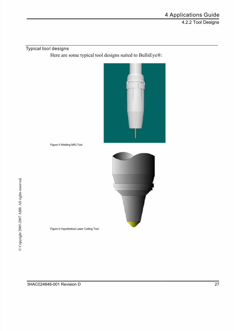
Typical too l designs
Here are some typical tool designs suited to BullsEye®:
Figure 5 Welding MIG Tool
Figure 6 Hypothetical Laser Cutting Tool
8/16/2019 Bullseye Manual RevD En
http://slidepdf.com/reader/full/bullseye-manual-revd-en 30/104
4 Applications Guide
4.2.3 TCP z-axis inline with mounting surface z-axis not supported
28 3HAC024846-001 Revision D
© C
o p y r i g h t 2 0 0 5 - 2 0 0 7 A B B .
A l l r i g h t s r e s e r v e d .
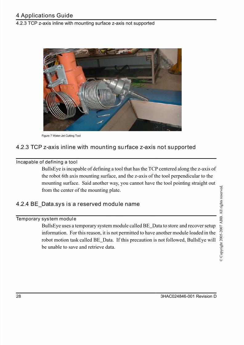
Figure 7 Water-Jet Cutting Tool
4.2.3 TCP z-axis inl ine with mounting surface z-axis not supported
Incapable of defining a too l
BullsEye is incapable of defining a tool that has the TCP centered along the z-axis of
the robot 6th axis mounting surface, and the z-axis of the tool perpendicular to the
mounting surface. Said another way, you cannot have the tool pointing straight out
from the center of the mounting plate.
4.2.4 BE_Data.sys is a reserved module name
Temporary system module
BullsEye uses a temporary system module called BE_Data to store and recover setup
information. For this reason, it is not permitted to have another module loaded in the
robot motion task called BE_Data. If this precaution is not followed, BullsEye will be unable to save and retrieve data.

8/16/2019 Bullseye Manual RevD En
http://slidepdf.com/reader/full/bullseye-manual-revd-en 31/104
5 User’s Guid
5.1 Safe
3HAC024846-001 Revision D 2
© C
o p y r i g h t 2 0 0 5 - 2 0 0 7 A B B .
A l l r i g h t s r e s e r v e d .
5 User’s Guide
5.1 Safety
Failure to follow safety guidelines presented throughout this manual can result in property
damage, serious injury, or death!
The power supply must always be switched off whenever work is carried out in the control
cabinet
Note:
Even though the power is switched off at the robot controller, there may be energized cables
connected to external equipment and are consequently not affected by the mains switch on
the controller.
8/16/2019 Bullseye Manual RevD En
http://slidepdf.com/reader/full/bullseye-manual-revd-en 32/104
5 User’s Guide
5.2 Overview
30 3HAC024846-001 Revision D
© C
o p y r i g h t 2 0 0 5 - 2 0 0 7 A B B .
A l l r i g h t s r e s e r v e d .
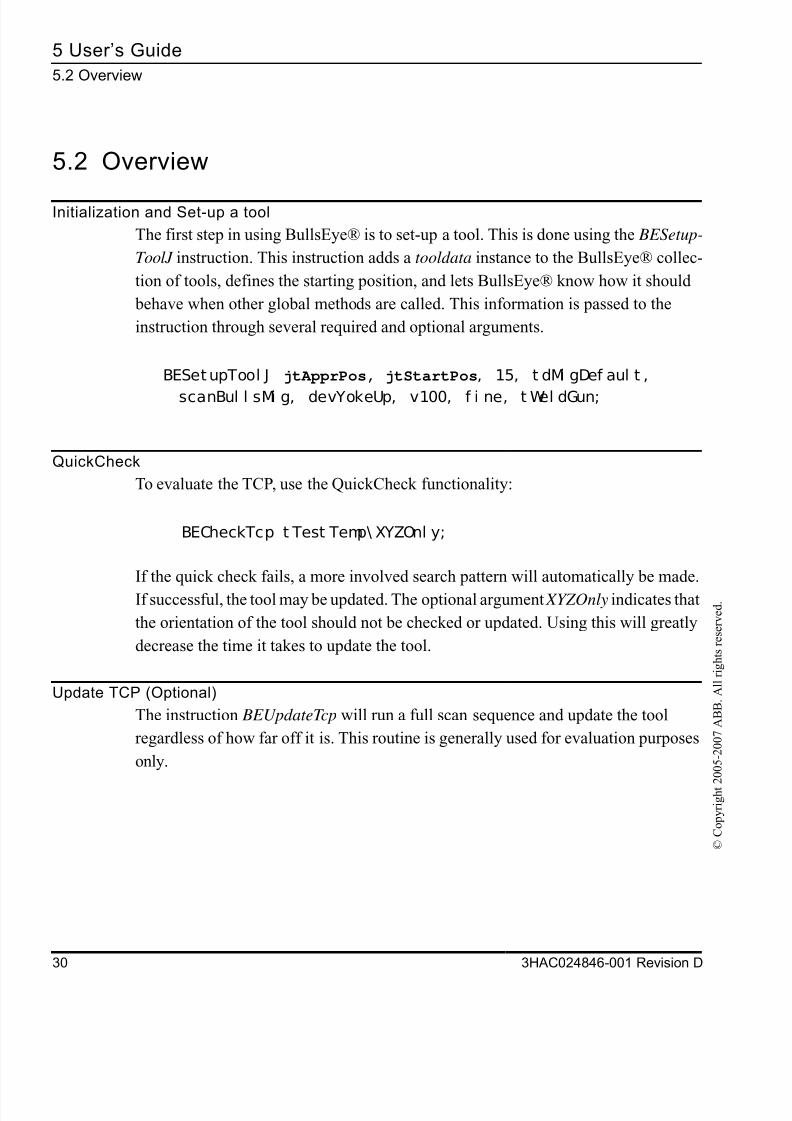
5.2 Overview
Initialization and Set-up a tool
The first step in using BullsEye® is to set-up a tool. This is done using the BESetup-
ToolJ instruction. This instruction adds a tooldata instance to the BullsEye® collec-
tion of tools, defines the starting position, and lets BullsEye® know how it should
behave when other global methods are called. This information is passed to the
instruction through several required and optional arguments.
BESetupTool J jtApprPos, jtStartPos, 15, t dMi gDef aul t ,
scanBul l sMi g, devYokeUp, v100, f i ne, t Wel dGun;
QuickCheck
To evaluate the TCP, use the QuickCheck functionality:
BECheckTcp t Test Temp\ XYZOnl y;
If the quick check fails, a more involved search pattern will automatically be made.
If successful, the tool may be updated. The optional argument XYZOnly indicates that
the orientation of the tool should not be checked or updated. Using this will greatly
decrease the time it takes to update the tool.
Update TCP (Optional)
The instruction BEUpdateTcp will run a full scan sequence and update the tool
regardless of how far off it is. This routine is generally used for evaluation purposes
only.

8/16/2019 Bullseye Manual RevD En
http://slidepdf.com/reader/full/bullseye-manual-revd-en 33/104
5 User’s Guid
5.3 Data Storag
3HAC024846-001 Revision D 3
© C
o p y r i g h t 2 0 0 5 - 2 0 0 7 A B B .
A l l r i g h t s r e s e r v e d .
5.3 Data Storage
File type
The data is stored in a text file on the robot’s file management system. The format of
the file represents a RAPID module allowing BullsEye® to read the data into the
controller when it needs to access the saved data.
Storage
The file is stored in the following directory, with a name like, “$HOME\BullsEye®
\BE_Data_T_ROB1.sys”, where “T_ROB1” is the name of the task. Each robot task
that is using BullsEye® will have its own data file. The directory path may not bechanged.
Automatic save
The data file is automatically saved after each BullsEye® update action. It is auto-
matically read before each BullsEye® check action. If the file is missing, BullsEye®
assumes that no saved data is available and will force the user to execute a BullsEye®
setup routine.
Backup
The data file will be included in the Backup when a system Backup is ordered. A
system restored from a backup will retain the stored data.
BullsEye uses a temporary system module called BE_Data to store and recover setup
information. For this reason, it is not permitted to have another module loaded in the robot
motion task called BE_Data. If this precaution is not followed, BullsEye will be unable to save
and retrieve data.

8/16/2019 Bullseye Manual RevD En
http://slidepdf.com/reader/full/bullseye-manual-revd-en 34/104
5 User’s Guide
5.4 Using BullsEye®
32 3HAC024846-001 Revision D
© C
o p y r i g h t 2 0 0 5 - 2 0 0 7 A B B .
A l l r i g h t s r e s e r v e d .
5.4 Using BullsEye®
About th is sect ion
The user module in your system may look different than the basic example used in
this procedure, however, all user modules will make calls to BullsEye® methods like
BECheckTcp and BESetupToolJ . This section focuses solely on the flexibility of
these global methods themselves.
After reading th is section you wi ll know how to :
1. Reference appropriate scan data, device data, and tool design data when calling thesetup routine, BESetupToolJ.
2. Create copies of default scan data, device data, and tool design data, make changes
to those copies, and ultimately reference these new instances.
3. Use the optional arguments in all the global methods to tailor the behavior to your
needs.
8/16/2019 Bullseye Manual RevD En
http://slidepdf.com/reader/full/bullseye-manual-revd-en 35/104
5 User’s Guid
5.4.1 The Global Methods of BullsEye
3HAC024846-001 Revision D 3
© C
o p y r i g h t 2 0 0 5 - 2 0 0 7 A B B .
A l l r i g h t s r e s e r v e d .
5.4.1 The Global Methods of BullsEye®
The term Global Method
BullsEye® has several global methods used to access BullsEye® features. The term
global methods, refers to RAPID instructions that are visible from your RAPID pro
gram. That is to say that the instructions may be called from your RAPID program
in the same way you might make a call to the MoveJ instruction.
The Bul lsEye® global methods are:
About th is section
This section will focus on a discussion of BESetupToolJ , followed by an overview of
BECheckTcp. More detailed, technical descriptions of any of these global methods
may be found in section Instructions on page 73.
BECheckTcp Check the TCP
BEDebugState Turn on/off debug logging.
BERefPointer Move to the reference pointer.
BESetupToolJ Setup the tool by making an initial measurement.
BETcpExtend Change the TCP extension without re-measuring the tool.
BEUpdateTcp Measure the tool and update regardless of the measured error.
8/16/2019 Bullseye Manual RevD En
http://slidepdf.com/reader/full/bullseye-manual-revd-en 36/104
5 User’s Guide
5.4.2 Set-up a tool
34 3HAC024846-001 Revision D
© C
o p y r i g h t 2 0 0 5 - 2 0 0 7 A B B .
A l l r i g h t s r e s e r v e d .
5.4.2 Set-up a tool
Action
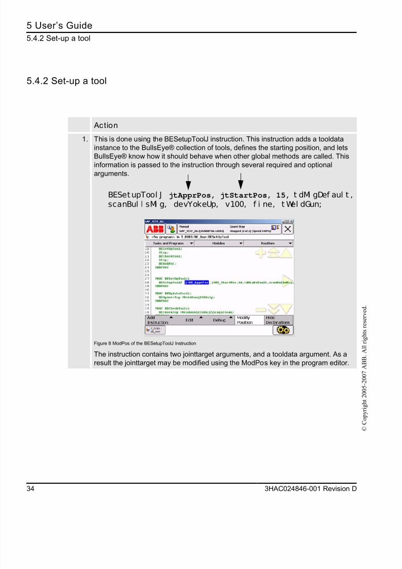
1. This is done using the BESetupToolJ instruction. This instruction adds a tooldata
instance to the BullsEye® collection of tools, defines the starting position, and lets
BullsEye® know how it should behave when other global methods are called. This
information is passed to the instruction through several required and optional
arguments.
BESetupTool J jtApprPos, jtStartPos, 15, t dMi gDef aul t ,scanBul l sMi g, devYokeUp, v100, f i ne, t Wel dGun;
Figure 8 ModPos of the BESetupToolJ Instruction
The instruction contains two jointtarget arguments, and a tooldata argument. As a
result the jointtarget may be modified using the ModPos key in the program editor.
8/16/2019 Bullseye Manual RevD En
http://slidepdf.com/reader/full/bullseye-manual-revd-en 37/104
5 User’s Guid
5.4.2 Set-up a to
3HAC024846-001 Revision D 3
© C
o p y r i g h t 2 0 0 5 - 2 0 0 7 A B B .
A l l r i g h t s r e s e r v e d .
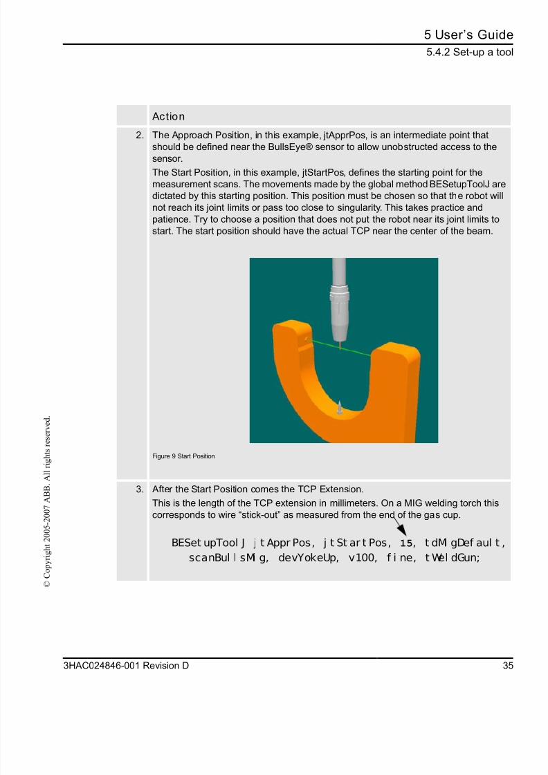
2. The Approach Position, in this example, jtApprPos, is an intermediate point thatshould be defined near the BullsEye® sensor to allow unobstructed access to the
sensor.
The Start Position, in this example, jtStartPos, defines the starting point for the
measurement scans. The movements made by the global method BESetupToolJ are
dictated by this starting position. This position must be chosen so that the robot will
not reach its joint limits or pass too close to singularity. This takes practice and
patience. Try to choose a position that does not put the robot near its joint limits to
start. The start position should have the actual TCP near the center of the beam.
Figure 9 Start Position
3. After the Start Position comes the TCP Extension.
This is the length of the TCP extension in millimeters. On a MIG welding torch this
corresponds to wire “stick-out” as measured from the end of the gas cup.
BESet upTool J j t Appr Pos, j t St ar t Pos, 15, t dMi gDef aul t , scanBul l sMi g, devYokeUp, v100, f i ne, t Wel dGun;
Action
8/16/2019 Bullseye Manual RevD En
http://slidepdf.com/reader/full/bullseye-manual-revd-en 38/104
5 User’s Guide
5.4.2 Set-up a tool
36 3HAC024846-001 Revision D
© C
o p y r i g h t 2 0 0 5 - 2 0 0 7 A B B .
A l l r i g h t s r e s e r v e d .
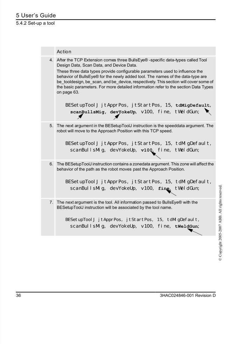
4. After the TCP Extension comes three BullsEye® -specific data-types called ToolDesign Data, Scan Data, and Device Data.
These three data types provide configurable parameters used to influence the
behavior of BullsEye® for the newly added tool. The names of the data-type are
be_tooldesign, be_scan, and be_device, respectively. This section will cover some of
the basic parameters. For more detailed information refer to the section Data Types
on page 63.
BESet upTool J j t Appr Pos, j t St ar t Pos, 15, tdMigDefault,
scanBullsMig, devYokeUp, v100, f i ne, t Wel dGun;
5. The next argument in the BESetupToolJ instruction is the speeddata argument. The
robot will move to the Approach Position with this TCP speed.
BESet upTool J j t Appr Pos, j t St ar t Pos, 15, t dMi gDef aul t ,
scanBul l sMi g, devYokeUp, v100, f i ne, t Wel dGun;
6. The BESetupToolJ instruction contains a zonedata argument. This zone will affect the
behavior of the path as the robot moves past the Approach Position.
BESet upTool J j t Appr Pos, j t St ar t Pos, 15, t dMi gDef aul t ,scanBul l sMi g, devYokeUp, v100, fine, t Wel dGun;
7. The next argument is the tool. All information passed to BullsEye® with theBESetupToolJ instruction will be associated by the tool name.
BESet upTool J j t Appr Pos, j t St ar t Pos, 15, t dMi gDef aul t ,
scanBul l sMi g, devYokeUp, v100, f i ne, tWeldGun;
Action
8/16/2019 Bullseye Manual RevD En
http://slidepdf.com/reader/full/bullseye-manual-revd-en 39/104
5 User’s Guid
5.4.3 Default BullsEye® Dat
3HAC024846-001 Revision D 3
© C
o p y r i g h t 2 0 0 5 - 2 0 0 7 A B B .
A l l r i g h t s r e s e r v e d .
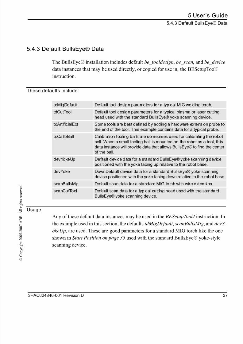
5.4.3 Default BullsEye® Data
The BullsEye® installation includes default be_tooldesign, be_scan, and be_device
data instances that may be used directly, or copied for use in, the BESetupToolJ
instruction.
These defaults include:
Usage
Any of these default data instances may be used in the BESetupToolJ instruction. In
the example used in this section, the defaults tdMigDefault , scanBullsMig, and devY
okeUp, are used. These are good parameters for a standard MIG torch like the one
shown in Start Position on page 35 used with the standard BullsEye® yoke-style
scanning device.
tdMigDefault Default tool design parameters for a typical MIG welding torch.
tdCutTool Default tool design parameters for a typical plasma or laser cutting
head used with the standard BullsEye® yoke scanning device.
tdArtificialExt Some tools are best defined by adding a hardware extension probe to
the end of the tool. This example contains data for a typical probe.
tdCalibBall Calibration tooling balls are sometimes used for calibrating the robot
cell. When a small tooling ball is mounted on the robot as a tool, this
data instance will provide data that allows BullsEye® to find the center
of the ball.
devYokeUp Default device data for a standard BullsEye® yoke scanning device
positioned with the yoke facing up relative to the robot base.
devYoke DownDefault device data for a standard BullsEye® yoke scanning
device positioned with the yoke facing down relative to the robot base
scanBullsMig Default scan data for a standard MIG torch with wire extension.
scanCutTool Default scan data for a typical cutting head used with the standard
BullsEye® yoke scanning device.
8/16/2019 Bullseye Manual RevD En
http://slidepdf.com/reader/full/bullseye-manual-revd-en 40/104
5 User’s Guide
5.4.4 Selecting Different BullsEye® Data
38 3HAC024846-001 Revision D
© C
o p y r i g h t 2 0 0 5 - 2 0 0 7 A B B .
A l l r i g h t s r e s e r v e d .
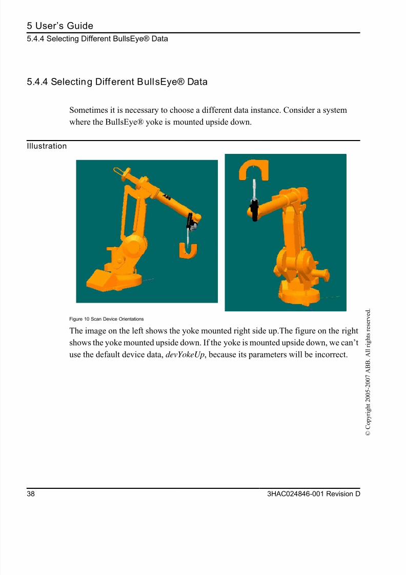
5.4.4 Selecting Different BullsEye® Data
Sometimes it is necessary to choose a different data instance. Consider a system
where the BullsEye® yoke is mounted upside down.
Illustration
Figure 10 Scan Device Orientations
The image on the left shows the yoke mounted right side up.The figure on the right
shows the yoke mounted upside down. If the yoke is mounted upside down, we can’t
use the default device data, devYokeUp, because its parameters will be incorrect.
8/16/2019 Bullseye Manual RevD En
http://slidepdf.com/reader/full/bullseye-manual-revd-en 41/104
5 User’s Guid
5.4.4 Selecting Different BullsEye® Dat
3HAC024846-001 Revision D 3
© C
o p y r i g h t 2 0 0 5 - 2 0 0 7 A B B .
A l l r i g h t s r e s e r v e d .
Instruction
Action
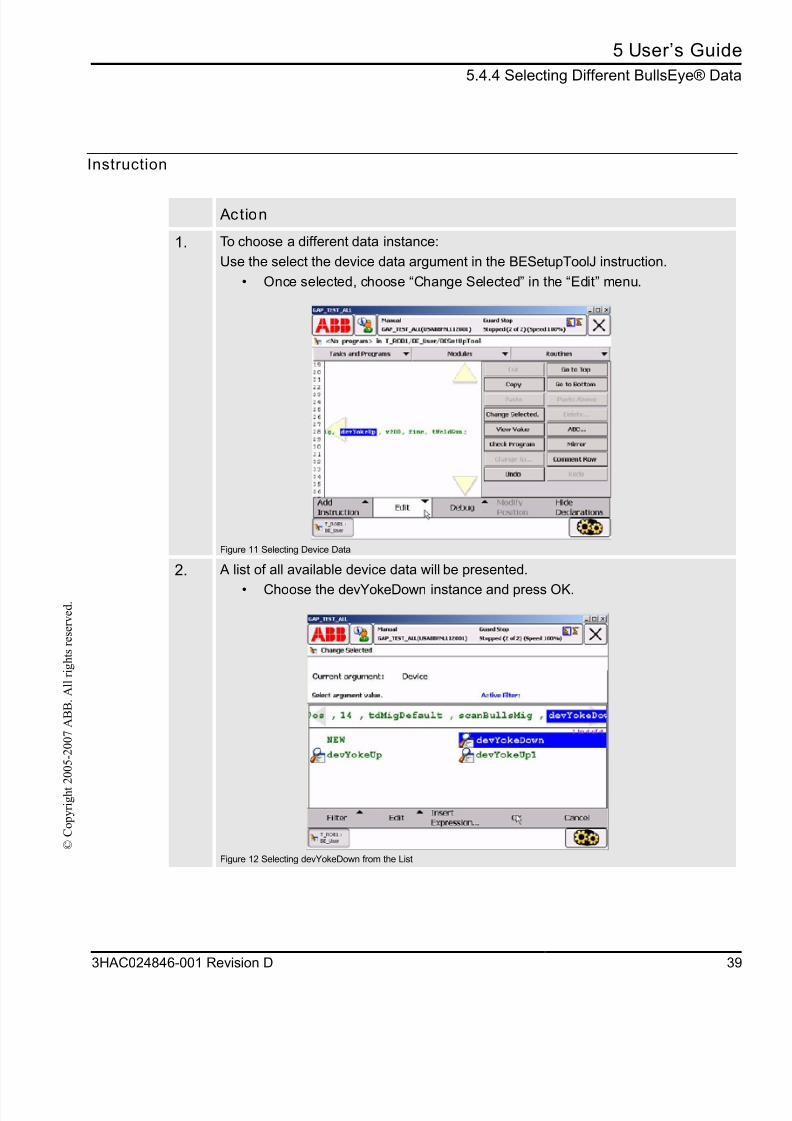
1. To choose a different data instance:
Use the select the device data argument in the BESetupToolJ instruction.
• Once selected, choose “Change Selected” in the “Edit” menu.
Figure 11 Selecting Device Data
2. A list of all available device data will be presented.
• Choose the devYokeDown instance and press OK.
Figure 12 Selecting devYokeDown from the List

8/16/2019 Bullseye Manual RevD En
http://slidepdf.com/reader/full/bullseye-manual-revd-en 42/104
5 User’s Guide
5.4.4 Selecting Different BullsEye® Data
40 3HAC024846-001 Revision D
© C
o p y r i g h t 2 0 0 5 - 2 0 0 7 A B B .
A l l r i g h t s r e s e r v e d .
3. The new device data is now added to the BESetupToolJ instruction. When theinstruction is run, the parameters included in devYokeDown will be associated with
tWeldGun.
BESet upTool J j t Appr Pos, j t St ar t Pos, 15, t dMi gDef aul t ,
scanBul l sMi g, devYokeDown, v100, f i ne, t Wel dGun;
Action
Note!
This general procedure is used for choosing new be_scan and be_tooldesign data, also.
8/16/2019 Bullseye Manual RevD En
http://slidepdf.com/reader/full/bullseye-manual-revd-en 43/104
5 User’s Guid
5.4.5 Creating New BullsEye® Data Instance
3HAC024846-001 Revision D 4
© C
o p y r i g h t 2 0 0 5 - 2 0 0 7 A B B .
A l l r i g h t s r e s e r v e d .
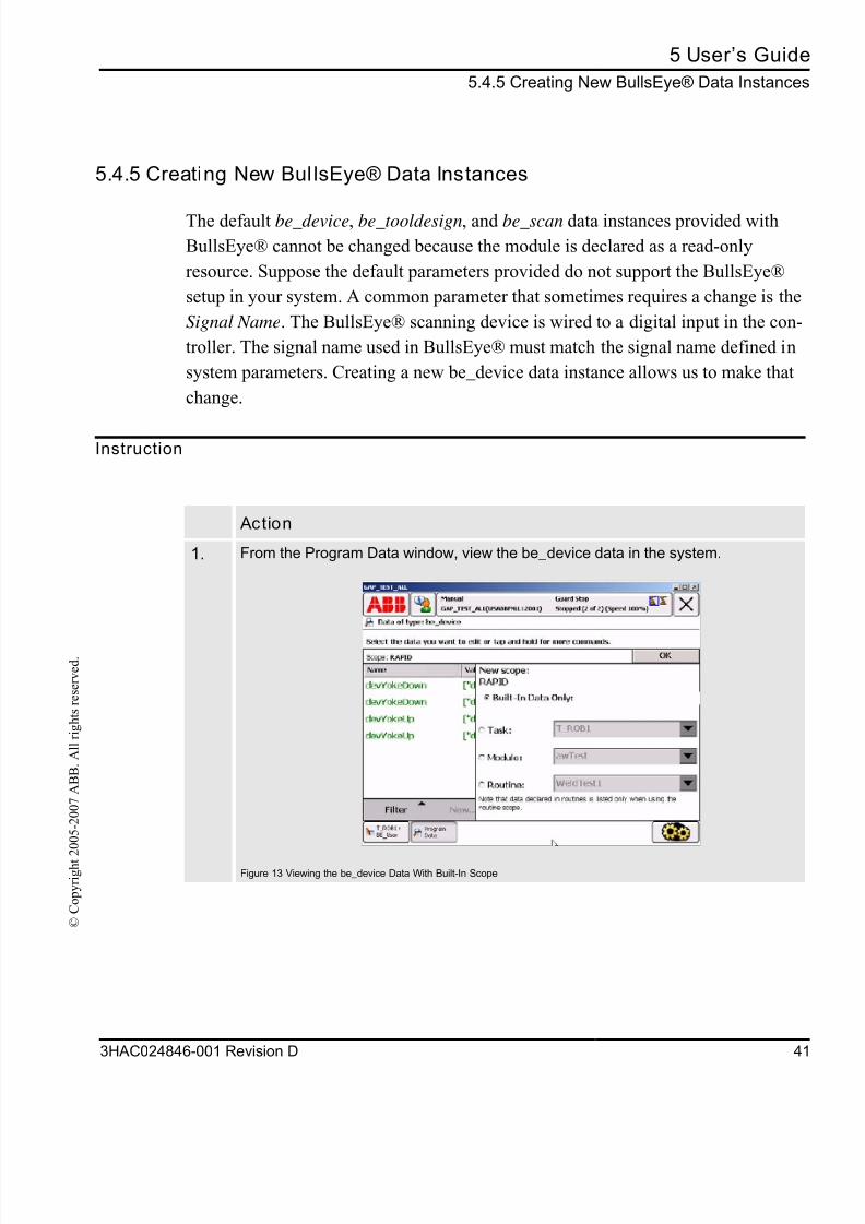
5.4.5 Creating New Bul lsEye® Data Instances
The default be_device, be_tooldesign, and be_scan data instances provided with
BullsEye® cannot be changed because the module is declared as a read-only
resource. Suppose the default parameters provided do not support the BullsEye®
setup in your system. A common parameter that sometimes requires a change is the
Signal Name. The BullsEye® scanning device is wired to a digital input in the con-
troller. The signal name used in BullsEye® must match the signal name defined in
system parameters. Creating a new be_device data instance allows us to make that
change.
Instruction
Action
1. From the Program Data window, view the be_device data in the system.
Figure 13 Viewing the be_device Data With Built-In Scope
8/16/2019 Bullseye Manual RevD En
http://slidepdf.com/reader/full/bullseye-manual-revd-en 44/104
5 User’s Guide
5.4.5 Creating New BullsEye® Data Instances
42 3HAC024846-001 Revision D
© C
o p y r i g h t 2 0 0 5 - 2 0 0 7 A B B .
A l l r i g h t s r e s e r v e d .
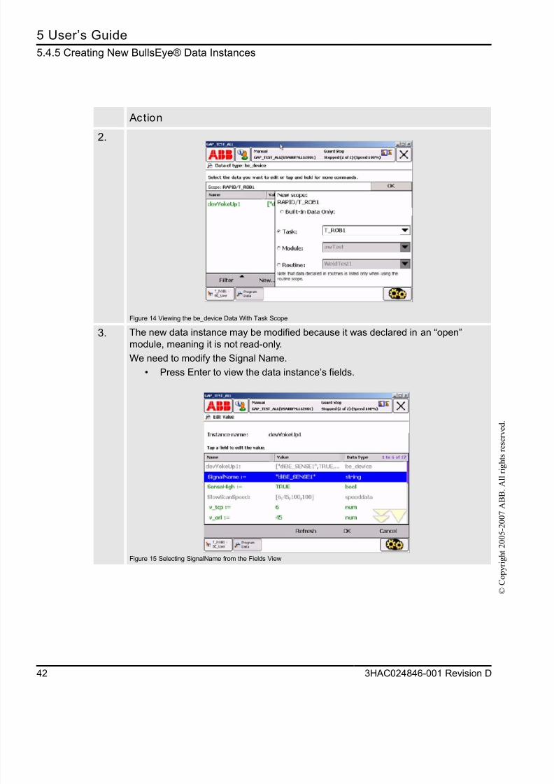
2.
Figure 14 Viewing the be_device Data With Task Scope
3. The new data instance may be modified because it was declared in an “open”
module, meaning it is not read-only.
We need to modify the Signal Name.
• Press Enter to view the data instance’s fields.
Figure 15 Selecting SignalName from the Fields View
Action
8/16/2019 Bullseye Manual RevD En
http://slidepdf.com/reader/full/bullseye-manual-revd-en 45/104
5 User’s Guid
5.4.5 Creating New BullsEye® Data Instance
3HAC024846-001 Revision D 4
© C
o p y r i g h t 2 0 0 5 - 2 0 0 7 A B B .
A l l r i g h t s r e s e r v e d .
I
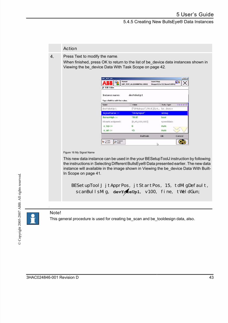
4. Press Text to modify the name.When finished, press OK to return to the list of be_device data instances shown in
Viewing the be_device Data With Task Scope on page 42.
Figure 16 My Signal Name
This new data instance can be used in the your BESetupToolJ instruction by following
the instructions in Selecting Different BullsEye® Data presented earlier. The new data
instance will available in the image shown in Viewing the be_device Data With Built-In Scope on page 41.
BESet upTool J j t Appr Pos, j t St ar t Pos, 15, t dMi gDef aul t ,
scanBul l sMi g, devYokeUp1, v100, f i ne, t Wel dGun;
Action
Note!
This general procedure is used for creating be_scan and be_tooldesign data, also.
8/16/2019 Bullseye Manual RevD En
http://slidepdf.com/reader/full/bullseye-manual-revd-en 46/104
5 User’s Guide
5.4.6 BullsEye® Data Parameters
44 3HAC024846-001 Revision D
© C
o p y r i g h t 2 0 0 5 - 2 0 0 7 A B B .
A l l r i g h t s r e s e r v e d .
5.4.6 BullsEye® Data Parameters
The parameter fields in be_device, be_scan, and be_tooldesign data are described in
their entirety in section Data Types on page 63. If the default data instances provided
by BullsEye® cannot solve your particular BullsEye® implementation problem,
review the detailed analysis of each BullsEye® datatype before attempting to create
your own versions.
Execution
When BESetupToolJ is executed, the robot will make a move to the Start Position,
via the Approach Position, that is defined in the instruction. It will begin searchingfor the scanning device beam. If it can locate it, the robot will begin executing a series
of scans to measure the TCP of the tool.
BullsEye® measures the TCP several times to verify that the measurements have
converged to a common solution. A typical setup should take about 10 minutes to
complete. If there is a problem with robot calibration, the tool mounting hardware,
or other factors not compensated for by BullsEye®, the setup routine will fail and
report a status message indicating the problem. In this case BullsEye® may attempt
to find a solution for up to 20 minutes before reporting a convergence error and halt-
ing execution.
The most common problem encountered while running the setup is a joint limit error.
Joint limit errors occur when the robot tries to move to a position that is outside the
working range of the robot. When this occurs, a new Start Position must be chosen
and the BESetupToolJ instruction re-executed. It takes some practice to be able to run
the setup on the first try. It is best to try running the BullsEye® before permanently
mounting the sensor, in case you find that it must be moved to complete the setup.
8/16/2019 Bullseye Manual RevD En
http://slidepdf.com/reader/full/bullseye-manual-revd-en 47/104
5 User’s Guid
5.4.7 QuickChec
3HAC024846-001 Revision D 4
© C
o p y r i g h t 2 0 0 5 - 2 0 0 7 A B B .
A l l r i g h t s r e s e r v e d .
5.4.7 QuickCheck
About QuickCheck
QuickCheck is the trade name for the TCP evaluation features offered by the global
method BECheckTcp. BECheckTcp may be called for any tool that has been initial-
ized and set up.
BECheckTcp t Wel dGun\ XYZOnl y\ Stat us: =beStat us;
FunctionWhen called, the robot makes a move to the Start Position via the Approach Position
Two complete scans are made. If the preliminary measurement shows a deviation, the
robot will continue to make a complete measurement of the tool. Otherwise, the robo
returns to the calling routine and no change is made to the TCP. If the tool is mea-
sured and found to have changed, then the tool is updated before returning to the
calling routine.
Automatic mode
When running with the key switch in Automatic Mode the update happens automat
ically without a prompt.
Manual mode
When running with the key switch in the Manual Teach Mode, the user will be
prompted for action before updating the tool.
Note!
It is common practice to call BECheckTcp after a certain time or after a certain number of parts
has been processed to ensure that the TCP is always correct.
8/16/2019 Bullseye Manual RevD En
http://slidepdf.com/reader/full/bullseye-manual-revd-en 48/104
5 User’s Guide
5.4.7 QuickCheck
46 3HAC024846-001 Revision D
© C
o p y r i g h t 2 0 0 5 - 2 0 0 7 A B B .
A l l r i g h t s r e s e r v e d .
Optional Arguments
Like the BESetupToolJ instruction, BECheckTcp has several optional arguments.
XYZOnly
One commonly used optional switch is XYZOnly. If selected, the instruction will
only update the translation portion of the tooldata when it is required to update the
TCP definition. In this case the orientation of the tool is unaffected. Using this switch
decreases the update time by about half. Keep in mind that large changes in TCP
translation without updating orientation can eventually lead to problems in cases
where tool orientation is critical as in a torch cleaning routine.
Status argument
Another commonly used optional argument is the Status argument. The Status argu-
ment returns an integer that may be evaluated in the calling RAPID code. Each error
condition returns a unique error number.
8/16/2019 Bullseye Manual RevD En
http://slidepdf.com/reader/full/bullseye-manual-revd-en 49/104
5 User’s Guid
5.5 BullsEye® Status Code
3HAC024846-001 Revision D 4
© C
o p y r i g h t 2 0 0 5 - 2 0 0 7 A B B .
A l l r i g h t s r e s e r v e d .
5.5 BullsEye® Status Codes
About status codes
BullsEye® uses status codes to report errors from the user instructions. The error
code may be captured using the INOUT Status parameter in BEUpdateTcp, BERef-
Pointer , and BECheckTcp.
5.5.1 Error codes
List of error codes
The following is a list of the error codes and a brief description for each. These errorcodes are global constants of the alias num-type, be_status.
BESuccess 1
If the instruction is executed in its entirety with no errors, Status will be set to
BESuccess.
BENoOverwrite 2
If the OverWrite flag was not set and the tool is already included in the BullsEye®
Collection, this code will be raised by BESetupToolJ. Add the optional switch,
OverWrite, to the instruction to over write the existing data.
BENoNameMatch 3
No data could be located for the tool selected. Re-initialize the tool with BESetupToolJ
to correct the problem.
BENoBEDataMod 4
The system module, BE_Data, appears to be missing. Load the module before
continuing.
BEArrayFull 5
BullsEye® will accept up to 5 tools. Remove a tool from the BullsEye® Collection withthe BERemoveTool method to free up space.
BEToolNotFound 6
No data could be located for the tool selected. Re-initialize the tool with BESetupToolJ
to correct the problem.
8/16/2019 Bullseye Manual RevD En
http://slidepdf.com/reader/full/bullseye-manual-revd-en 50/104
5 User’s Guide
5.5.1 Error codes
48 3HAC024846-001 Revision D
© C
o p y r i g h t 2 0 0 5 - 2 0 0 7 A B B .
A l l r i g h t s r e s e r v e d .
BEInvalidSignal 7
This digital input name used in the be_device data is invalid. Verify that the signalexists.
BEAliasSet 8
The connection to the digital input specified in the be_device data could not be made.
Verify that the signal exists and is accessible.
BERangeLimFail 9
A joint limit will be exceeded if BullsEye® attempts to run the scanning process. Try re-
initializing the tool with a new Start Position using BESetupToolJ, or try moving the
scanning device to a new location and re-initializing.
BERangeSingFail 10
The robot will run close to singularity if BullsEye® attempts to run the scanning process.
Try re-initializing the tool with a new Start Position using BESetupToolJ, or try moving
the scanning device to a new location and re-initializing.
BERangeTiltFail 11
No acceptable tilt direction could be found for the scanning process. Try re-initializing
the tool with a new Start Position using BESetupToolJ, or try moving the scanning
device to a new location and re-initializing.
BEScanPlaneErr 12
BullsEye® could not determine the scan plane of the device. Report this error to ABB.
BEBFrameNotRead 13
The base frame definition of the robot could not be found. Please verify that the robot
is referred to as the “master” in system parameters. Report this error to ABB if the
problem cannot be determined.
BEScanRadZero 14
The parameter, InitPatternRad, in be_scan data is negative or zero. For a standard
yoke-style beam-type scanning device, this value should be about 25mm. Correct the
data problem before retrying.
BEHeightSrchErr 15
The height search failed. Check that the proximity sensor in the tool is working properly
and check that the height search instruction is named correctly in be_scan data. The
height search instruction is tool-dependent and is not a part of the BullsEye® software.
8/16/2019 Bullseye Manual RevD En
http://slidepdf.com/reader/full/bullseye-manual-revd-en 51/104
5 User’s Guid
5.5.1 Error code
3HAC024846-001 Revision D 4
© C
o p y r i g h t 2 0 0 5 - 2 0 0 7 A B B .
A l l r i g h t s r e s e r v e d .
BEBeamNotFound 16
The robot could not locate the sensing beam of the scan device. Check to see that thetool is passing through the beam and that the sensor is triggering the digital input
associated with it.
BEBeamSpinErr 17
Although the beam was located, its orientation could not be determined.
BESrchErrInBeam 18
BullsEye® attempted to make a scan, but the start position of the scan broke the beam
Check that the tool dimensions are correct in be_tooldesign. Check that the scan
margins are sufficient in be_scan. Check that the scanning device is triggering properly
Check that the robot is calibrated.BESrchErrNoDet 19
BullsEye® attempted to make a scan, but the scanning device never detected the tool
Check that the tool dimensions are correct in be_tooldesign. Check that the scanning
device is triggering properly. Check that the robot is calibrated.
BENumOfScansErr 20
The number of redundant scans requested in the be_scan data, is less-than or equal
to zero, or is not an integer.
BEDiaZeroOrLess 21
While scanning to find the center of the tool, the diameter of the tool was found to be
less-than or equal to zero. Check that the tool dimensions are correct in be_tooldesign
Check that the scanning device is triggering properly. Check that the robot is calibrated
BESliceCountErr 22
BullsEye® will take “slices” of the tool to find the end of the tool. If it can’t find the endof the tool in a reasonable number of scans, the instruction will be aborted and this
message will be raised. Verify that the flag, Inverted, is set properly in be_device data
Verify that the slice thickness specified in <be_tooldesign>.SliceGap is appropriate.
Verify that the Start Position is defined correctly.
BEGetNewTcpMax 23BullsEye® will iterate until it converges to a TCP definition that is within the requested
Repeatability. If it cannot arrive at a good TCP after a reasonable number of iterations
the process will be aborted and this error code will be raised. This error can result if the
Repeatability, specified in the be_device data, is unreasonably small, or if the robot has
an accuracy problem. Robot accuracy problems can be caused by incorrect calibration
or damaged robot arm components.
8/16/2019 Bullseye Manual RevD En
http://slidepdf.com/reader/full/bullseye-manual-revd-en 52/104
5 User’s Guide
5.5.1 Error codes
50 3HAC024846-001 Revision D
© C
o p y r i g h t 2 0 0 5 - 2 0 0 7 A B B .
A l l r i g h t s r e s e r v e d .
BEBeamOriFail 24
The beam orientation could not be fine-tuned correctly. Check that the tool isperpendicular to the scan plane when at the Start Position.
BEGetTcpDelErr 25
BullsEye® failed to determine the change in the TCP for the current iteration. This
problem typically arises when the robot calibration is wrong, or when tool dimensions
specified in be_tooldesign are incorrect.
BERefPosSetErr 26
Reference Position data could not be written to BE_Data.
BERefToolSetErr 27
Reference Tool data could not be written to BE_Data.
BERefBeamSetErr 28
Reference Beam data could not be written to BE_Data.
BEBFrameDefErr 29
BullsEye® does not understand the base frame definition of the robot. Verify that the
manipulator parameters are correct (MOC.cfg).
BESetupAlready 30
This tool is already set-up. Use the OverWrite optional argument with BESetupToolJ toredo the setup.
BERefResetErr 31
The reference data could not be reset. This indicates that BullsEye® could not write to
the BE_Data module.
BESetupFailed 32
The instruction, BESetupToolJ, failed for some unknown reason.
BE Start Not Set 33
The Start Position is not set for this tool. Run BESetupToolJ to correct the problem.
BEToolNotSet 34
The tool is not set-up. Run BESetupToolJ to correct the problem.
8/16/2019 Bullseye Manual RevD En
http://slidepdf.com/reader/full/bullseye-manual-revd-en 53/104
5 User’s Guid
5.5.1 Error code
3HAC024846-001 Revision D 5
© C
o p y r i g h t 2 0 0 5 - 2 0 0 7 A B B .
A l l r i g h t s r e s e r v e d .
BEStartChanged 35
The Start Position has changed. This can only occur by manually changing data in theBE_Data module, loading a BE_Data module from a different robot, or by loading the
wrong version of the BE_Data module. Load the correct BE_Data module, or re-
initialize and run the setup instruction.
BEBeamMoveErr 36
BullsEye® has detected that the beam has moved. Re-run the setup.
BECheckErr 37
There was a problem in the BECheckTcp instruction. The cause is unknown.
BESkipUpdate 38
The TCP has moved, but the operator did not accept the change.
BEStrtningErr 39
An error occurred while straightening the tool. The tool may be very bent, the tool
dimensions may be wrong in be_tooldesign, or the scan margins may be too small in
be_scan.
BEAllNotSet 40
The tool is not completely set-up. Redo the setup by running BESetupToolJ. If the same
error occurs, re-initialize the tool with BESetupToolJ before running BESetupToolJ.
BEQuikRefNotDef 41
The QuickCheck functionality in BECheckTcp could not run because the Quick
Reference position was not saved during the setup. Redo the setup with BESetupToolJ
BEConvergErr 42
BullsEye® will iterate until it converges to a TCP definition that is within the requested
Repeatability. If it cannot arrive at a good TCP after a reasonable number of iterations
the process will be aborted and this error code will be raised. This error can result if the
Repeatability, specified in the be_device data, is unreasonably small, or if the robot has
an accuracy problem. Robot accuracy problems can be caused by incorrect calibration
or damaged robot arm components.
BEInstFwdErr 43
BESetupToolJ cannot be run in step-forward mode. Execute in continuous mode to set
up the tool.

8/16/2019 Bullseye Manual RevD En
http://slidepdf.com/reader/full/bullseye-manual-revd-en 54/104
5 User’s Guide
5.5.1 Error codes
52 3HAC024846-001 Revision D
© C
o p y r i g h t 2 0 0 5 - 2 0 0 7 A B B .
A l l r i g h t s r e s e r v e d .
BEGetGantryErr 44
This tool has been initialized with the optional UserFramePos. The optionalfunctionality is not working correctly and the execution has been aborted.
BEUnknownErr 300
An unknown error has occurred.
8/16/2019 Bullseye Manual RevD En
http://slidepdf.com/reader/full/bullseye-manual-revd-en 55/104
5 User’s Guid
5.6 Commonly Asked Question
3HAC024846-001 Revision D 5
© C
o p y r i g h t 2 0 0 5 - 2 0 0 7 A B B .
A l l r i g h t s r e s e r v e d .
5.6 Commonly Asked Questions
About th is sect ion
The following is a short list of commonly asked questions.
5.6.1 How do I configure the digital input signal?
BullsEye® scanning devices use a single digital input signal. The digital input must
be defined on an I/O board. The signal is commonly given the name diBE_SENSE1
CONST be_devi ce devYokeUp: =[ "di BE_SENSE1", TRUE, …CONST be_devi ce devYokeUp: =[ "di MyNewSense", TRUE, …
BullsEye® must be informed of the name of the digital input. The name of the signal
is defined in the be_device data instance that is passed into the BESetupToolJ instruc
tion. See be_device in the DataTypes section and BESetupToolJ in section Instruc-
tions on page 73 for more information.
If the signal name is different from the default names provided, new BullsEye®
device data must be created. For more information about this, see section Selecting
Different BullsEye® Data on page 38 .
5.6.2 How do I implement mult iple tools?
BullsEye® can handle up to five different tools at a time by simply calling BESetup
ToolJ with five different tools.
8/16/2019 Bullseye Manual RevD En
http://slidepdf.com/reader/full/bullseye-manual-revd-en 56/104
5 User’s Guide
5.6.3 How should robot carriers be configured?
54 3HAC024846-001 Revision D
© C
o p y r i g h t 2 0 0 5 - 2 0 0 7 A B B .
A l l r i g h t s r e s e r v e d .
5.6.3 How should robot carriers be configured?
Robots moved by carriers, such as tracks, must have the user frame coordination
defined for the carrier.
Example:
The following definition will not work with Bullseye...
MECHANI CAL_UNI T:
#
- name "TRACK" - use_r un_enabl e " " - use_act i vat i on_r el ay " " \
- use_br ake_r el ay "" - use_si ngl e_0 "TRACK" \
- st and_by_st at e - act i vat e_at _st ar t _up -deact i vat i on_f or bi dden
It should look like this...
MECHANI CAL_UNI T:
#
- name "TRACK" - use_r un_enabl e " " - use_act i vat i on_r el ay " " \
- use_br ake_r el ay "" - use_si ngl e_0 "TRACK" -al l ow_move_of _user _f r ame \
- st and_by_st at e - act i vat e_at _st ar t _up -deact i vat i on_f or bi dden
This is addition is needed to support coordinated work objects that have the user
frame moved by the track. It is always recommended to define tracks and other robot
carriers this way. Doing so also improves the usability of the system for other reasons
beyond the BullsEye requirements.
In addition to these mechanical unit settings, we also recommend that the BullsEye
sensor yoke be mounted to move with the robot. Doing so ensures that vibrations in
the robot carrier do not affect the relationship between the BullsEye sensor yoke and
the robot arm. Vibrations can yield poor TCP quality. Mounting the sensor with the
robot also allows the possibility of executing TCP checks anywhere in the working
range of the robot carrier. This can cut TCP checking time tremendously.
8/16/2019 Bullseye Manual RevD En
http://slidepdf.com/reader/full/bullseye-manual-revd-en 57/104
5 User’s Guid
5.6.4 How do I set up BullsEye® when the robot is moved by a track
3HAC024846-001 Revision D 5
© C
o p y r i g h t 2 0 0 5 - 2 0 0 7 A B B .
A l l r i g h t s r e s e r v e d .
5.6.4 How do I set up BullsEye® when the robot is moved by a track?
If the BullsEye® scanning device is mounted on the carrier with the robot, no
changes are needed. This is the preferred method since it negates the positional inac
curacy of the robot carrier. If the BullsEye® scanning device is fixed in the world,
then a flag must be set in the be_device data to inform BullsEye®.
CONST be_devi ce devYokeUpTr ack: =[ "di BE_SENSE" ,
TRUE, [ 6, 45, 100, 100] , [ 40, 45, 100, 100] , 0. 10,
FALSE, FALSE, TRUE] ;
The flag in the device data is called MovedWithRobot . For more information see
section be_device, Device data on page 63.
5.6.5 Can I change my TCP extension without rerunning the init ialization?
Yes. Use the BETcpExtend instruction described in section Instructions on page 73
5.6.6 Can the BullsEye® yoke be mounted in any orientation?
Yes, but the BullsEye® scanning device must be mounted so that the scan plane is
parallel with the robot’s physical base surface.
8/16/2019 Bullseye Manual RevD En
http://slidepdf.com/reader/full/bullseye-manual-revd-en 58/104
5 User’s Guide
5.6.7 How should robot carriers be configured?
56 3HAC024846-001 Revision D
© C
o p y r i g h t 2 0 0 5 - 2 0 0 7 A B B .
A l l r i g h t s r e s e r v e d .
5.6.7 How should robot carriers be configured?
Robots moved by carriers, such as tracks, must have the user frame coordination
defined for the carrier.
Example:
The following definition will not work with Bullseye...
MECHANI CAL_UNI T:#- name "TRACK" - use_r un_enabl e " " - use_act i vat i on_r el ay "" -use_br ake_r el ay "" \
- use_si ngl e_0 "TRACK" - st and_by_st at e \- act i vat e_at _st ar t _up - deact i vat i on_f or bi dden
It should look like this...
#MECHANI CAL_UNI T:#- name "TRACK" - use_r un_enabl e " " - use_act i vat i on_r el ay "" -use_br ake_r el ay "" \- use_si ngl e_0 "TRACK" - al l ow_move_of _user _f r ame - st and_by_st ate \- act i vat e_at _st ar t _up - deact i vat i on_f or bi dden
This addition is needed to support coordinated work objects that have the user frame
moved by the track.
Note:
It is always recommended to define tracks and other robot carriers this way. Doing so also
improves the usability of the system for other reasons beyond BullsEye requirements.
8/16/2019 Bullseye Manual RevD En
http://slidepdf.com/reader/full/bullseye-manual-revd-en 59/104
5 User’s Guid
5.6.7 How should robot carriers be configured
3HAC024846-001 Revision D 5
© C
o p y r i g h t 2 0 0 5 - 2 0 0 7 A B B .
A l l r i g h t s r e s e r v e d .
In addition to mechanical unit settings
Action
1. We also recommend that the BullsEye sensor yoke be mounted to move with the
robot.
Doing so ensures that vibrations in the robot carrier do not effect the relationship
between the BullsEye sensor yoke and the robot arm
Caution:
Vibrations can yield poor TCP quality.
Mounting the sensor with the robot also allows the possibility of executing TCPchecks anywhere in the working range of the robot carrier.
This can cut TCP checking time tremendously.
8/16/2019 Bullseye Manual RevD En
http://slidepdf.com/reader/full/bullseye-manual-revd-en 60/104
5 User’s Guide
5.6.8 How do I set up a non-ABB supplied IO device?
58 3HAC024846-001 Revision D
© C
o p y r i g h t 2 0 0 5 - 2 0 0 7 A B B .
A l l r i g h t s r e s e r v e d .
5.6.8 How do I set up a non-ABB supplied IO device?
Only ABB IO devices are guaranteed to work with BullsEye. Many IO devices from
other vendors are too slow or too unrepeatable to allow BullsEye to work correctly.
When using non-ABB devices, you may need to slow the scan speeds substantially
to improve accuracy.
A WAGO I/O device, for example, may be used in the COS (Change of State) mode,
but the PIT (Production Inhibit Time) should be reduced as much as possible, pref-
erably to zero. This is done in the ABB Controller I/O configuration parameters, in:
<I/O> - <Unit type> - <Production inhibit time>.
8/16/2019 Bullseye Manual RevD En
http://slidepdf.com/reader/full/bullseye-manual-revd-en 61/104
5 User’s Guid
5.6.9 What is a "convergence error"
3HAC024846-001 Revision D 5
© C
o p y r i g h t 2 0 0 5 - 2 0 0 7 A B B .
A l l r i g h t s r e s e r v e d .
5.6.9 What is a "convergence error"?
BullsEye measures the TCP more than once during the setup. It converges on a solu
tion that is within limits influenced by the be_device field, "Repeatability". If the
deviation between two TCP measurements cannot be reduced to a level specified by
the Repeatability value, BullsEye eventually times-out and reports a "convergence
error".
Convergence errors can occur for a variety of reasons:
• Incorrect parameters are used in the setup.
This may be corrected by fixing the parameter values to match the tool and
scanning equipment.
• The tool is not mounted securely or tool mount bracket is too flexible.
This may be corrected by improving the tool mount.
• The relationship between the BullsEye sensor and the robot base is not solid.
This may be corrected by improving the mounting structures.
• The IO system is not responsive enough.
This may be corrected by reducing the search speeds.
• The IO not repeatable enough.
Non-ABB IO equipment could be improved by changing the configuration. See
section How do I set up a non-ABB supplied IO device? on page 58.
• Motor calibration wrong.
Check calibration.
• Inaccurate robot due to bearing imperfections.
No robot is perfect, but some are worse than others. Increase the Repeatability
value.
• The BullsEye sensor is faulty.
Occasionally there are problems with the optical sensor. These must be replaced
8/16/2019 Bullseye Manual RevD En
http://slidepdf.com/reader/full/bullseye-manual-revd-en 62/104
5 User’s Guide
5.6.10 How do I setup BullsEye to calibrate a tool like this?
60 3HAC024846-001 Revision D
© C
o p y r i g h t 2 0 0 5 - 2 0 0 7 A B B .
A l l r i g h t s r e s e r v e d .
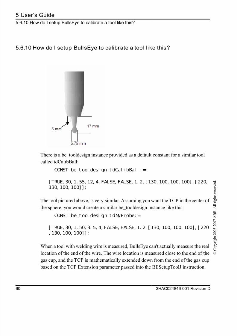
5.6.10 How do I setup BullsEye to calibrate a tool like this?
There is a be_tooldesign instance provided as a default constant for a similar tool
called tdCalibBall:
CONST be_t ool desi gn t dCal i bBal l : =
[ TRUE, 30, 1, 55, 12, 4, FALSE, FALSE, 1. 2, [ 130, 100, 100, 100] , [ 220,130, 100, 100] ] ;
The tool pictured above, is very similar. Assuming you want the TCP in the center of
the sphere, you would create a similar be_tooldesign instance like this:
CONST be_t ool desi gn t dMyProbe: =
[ TRUE, 30, 1, 50, 3. 5, 4, FALSE, FALSE, 1. 2, [ 130, 100, 100, 100] , [ 220
, 130, 100, 100] ] ;
When a tool with welding wire is measured, BullsEye can't actually measure the real
location of the end of the wire. The wire location is measured close to the end of the
gas cup, and the TCP is mathematically extended down from the end of the gas cup
based on the TCP Extension parameter passed into the BESetupToolJ instruction.
8/16/2019 Bullseye Manual RevD En
http://slidepdf.com/reader/full/bullseye-manual-revd-en 63/104
5 User’s Guid
5.6.10 How do I setup BullsEye to calibrate a tool like this
3HAC024846-001 Revision D 6
© C
o p y r i g h t 2 0 0 5 - 2 0 0 7 A B B .
A l l r i g h t s r e s e r v e d .
This approach works well for welding torches because the wire is often bent in an
unpredictable direction and the length will vary. However, for a tool like the probe
pictured, it is more accurate to measure the end of the tool where the TCP actually is
because we don't have to worry about variation in location.
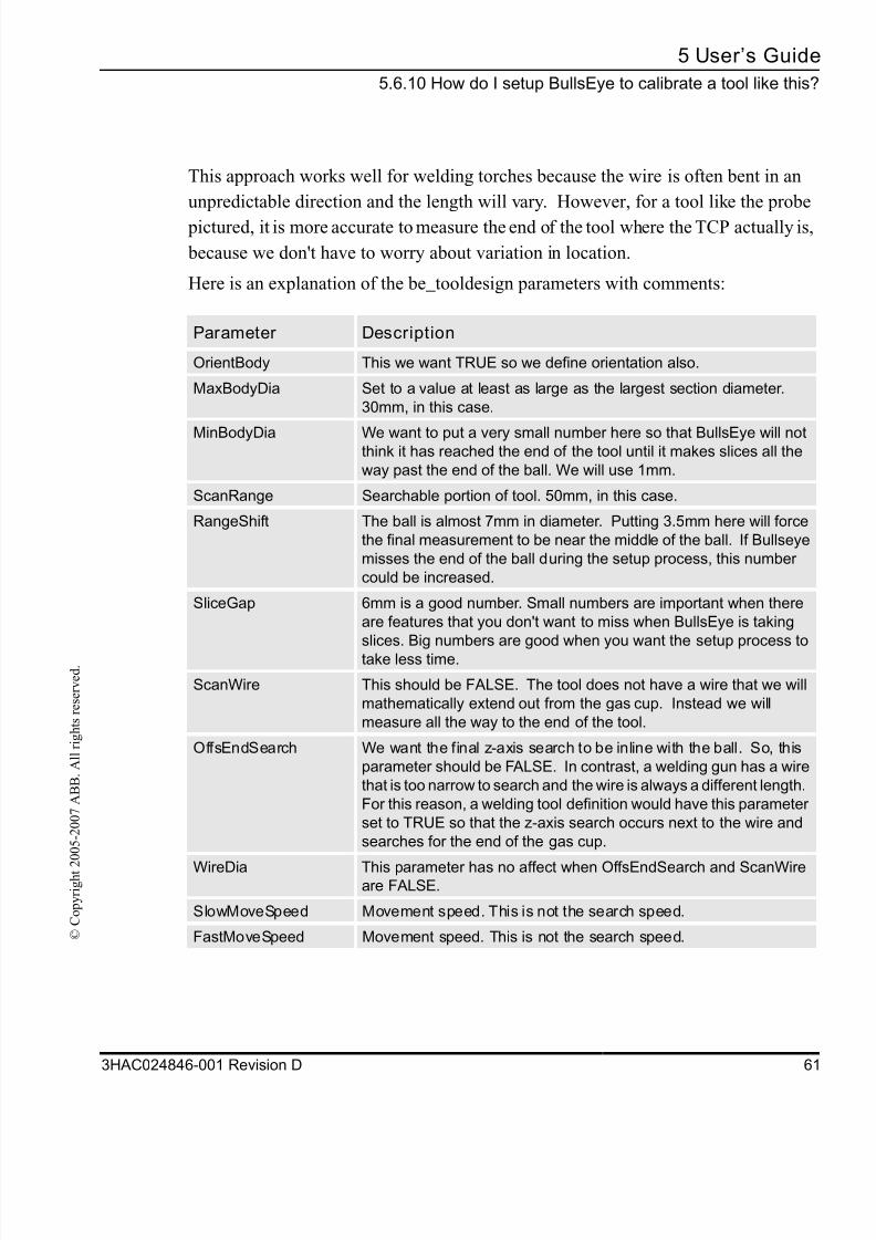
Here is an explanation of the be_tooldesign parameters with comments:
Parameter Description
OrientBody This we want TRUE so we define orientation also.
MaxBodyDia Set to a value at least as large as the largest section diameter.
30mm, in this case.
MinBodyDia We want to put a very small number here so that BullsEye will notthink it has reached the end of the tool until it makes slices all the
way past the end of the ball. We will use 1mm.
ScanRange Searchable portion of tool. 50mm, in this case.
RangeShift The ball is almost 7mm in diameter. Putting 3.5mm here will force
the final measurement to be near the middle of the ball. If Bullseye
misses the end of the ball during the setup process, this number
could be increased.
SliceGap 6mm is a good number. Small numbers are important when there
are features that you don't want to miss when BullsEye is taking
slices. Big numbers are good when you want the setup process to
take less time.
ScanWire This should be FALSE. The tool does not have a wire that we will
mathematically extend out from the gas cup. Instead we will
measure all the way to the end of the tool.
OffsEndSearch We want the final z-axis search to be inline with the ball. So, this
parameter should be FALSE. In contrast, a welding gun has a wire
that is too narrow to search and the wire is always a different length.
For this reason, a welding tool definition would have this parameter
set to TRUE so that the z-axis search occurs next to the wire and
searches for the end of the gas cup.
WireDia This parameter has no affect when OffsEndSearch and ScanWireare FALSE.
SlowMoveSpeed Movement speed. This is not the search speed.
FastMoveSpeed Movement speed. This is not the search speed.

8/16/2019 Bullseye Manual RevD En
http://slidepdf.com/reader/full/bullseye-manual-revd-en 64/104
5 User’s Guide
5.6.10 How do I setup BullsEye to calibrate a tool like this?
62 3HAC024846-001 Revision D
© C
o p y r i g h t 2 0 0 5 - 2 0 0 7 A B B .
A l l r i g h t s r e s e r v e d .
Lastly, the TCP Extension passed into the BESetupToolJ instruction, must be fixed...
BESet upTool J j t BEAppr Pos, j t BESt ar t Pos, - 3. 375 , t dMyPr obe. . .
A negative number will move the TCP from the end of the ball to the center of the
ball. The default settings for be_scan and be_device will work fine for a standard
ABB IO board.
8/16/2019 Bullseye Manual RevD En
http://slidepdf.com/reader/full/bullseye-manual-revd-en 65/104
6 Software Referenc
6.1 Data Type
3HAC024846-001 Revision D 6
© C
o p y r i g h t 2 0 0 5 - 2 0 0 7 A B B .
A l l r i g h t s r e s e r v e d .
6 Software Reference
6.1 Data Types
6.1.1 be_device, Device data
About be_device
This data structure contains parameters that are used to describe the scanning device's
properties.
Components
SignalName Datatype: string
Digital input name used by the scanning device.
SenseHigh Datatype: bool
Set to true if signal is high when the detecting the tool.
SlowScanSpeed Datatype: speeddata
Slow scans will be executed with this speed setting.
See the RAPID Reference Manual for an explanation of speeddata.
FastScanSpeed Datatype: speeddata
Fast scans will be executed with this speed setting.
See the RAPID Reference Manual for an explanation of speeddata.
Repeatability Datatype: num
The expected repeatability for TCP measurements. This number should be about twice
that of the published repeatability for the robot arm. This equates to about +/- 0.12mm
for an IRB-1400. Other factors, such as torch leads exerting undue force on the tool
mount bracket, may have an adverse affect on the repeatability. In such cases it may
be necessary to increase Repeatability in order for the robot to find an acceptable solu
tion. A convergence error is reported via the BullsEye error code argument when thesystem cannot reach the desired repeatability within a reasonable time.
Units: mm
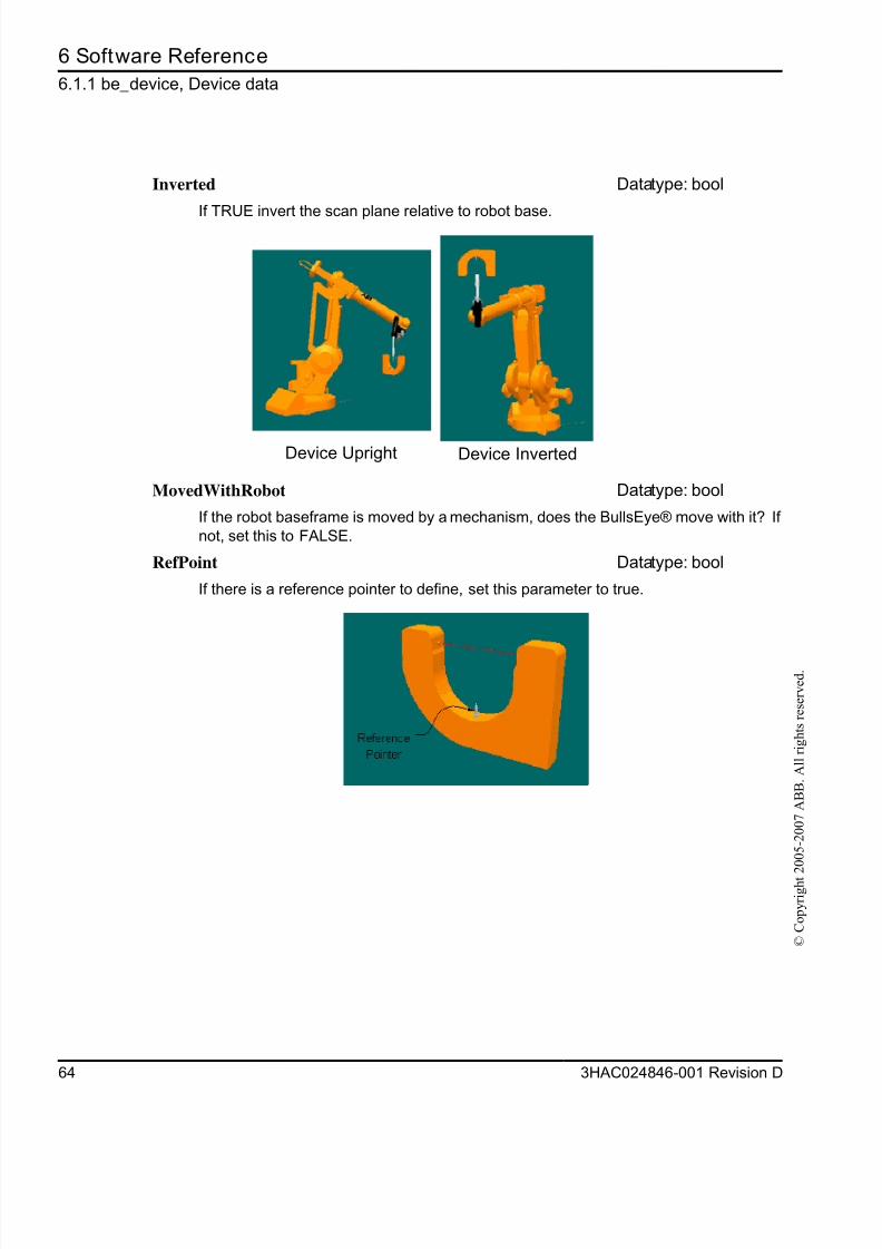
8/16/2019 Bullseye Manual RevD En
http://slidepdf.com/reader/full/bullseye-manual-revd-en 66/104
6 Software Reference
6.1.1 be_device, Device data
64 3HAC024846-001 Revision D
© C
o p y r i g h t 2 0 0 5 - 2 0 0 7 A B B .
A l l r i g h t s r e s e r v e d .
Inverted Datatype: bool
If TRUE invert the scan plane relative to robot base.
MovedWithRobot Datatype: bool
If the robot baseframe is moved by a mechanism, does the BullsEye® move with it? If
not, set this to FALSE.
RefPoint Datatype: bool
If there is a reference pointer to define, set this parameter to true.
Device Upright Device Inverted
8/16/2019 Bullseye Manual RevD En
http://slidepdf.com/reader/full/bullseye-manual-revd-en 67/104
6 Software Referenc
6.1.1 be_device, Device dat
3HAC024846-001 Revision D 6
© C
o p y r i g h t 2 0 0 5 - 2 0 0 7 A B B .
A l l r i g h t s r e s e r v e d .
Structure
<dataobject of be_device>
<SignalName of string>
<SenseHigh of bool>
<SlowScanSpeed of speeddata>
<FastScanSpeed of speeddata>
< Repeatability of num>
< Inverted of bool>
< MovedWithRobot of bool>
< RefPoint of bool>
Related information
Described in:
BESetupToolJ Instructions on page 73
be_scan Data Types on page 63
be_tooldesign Data Types on page 63
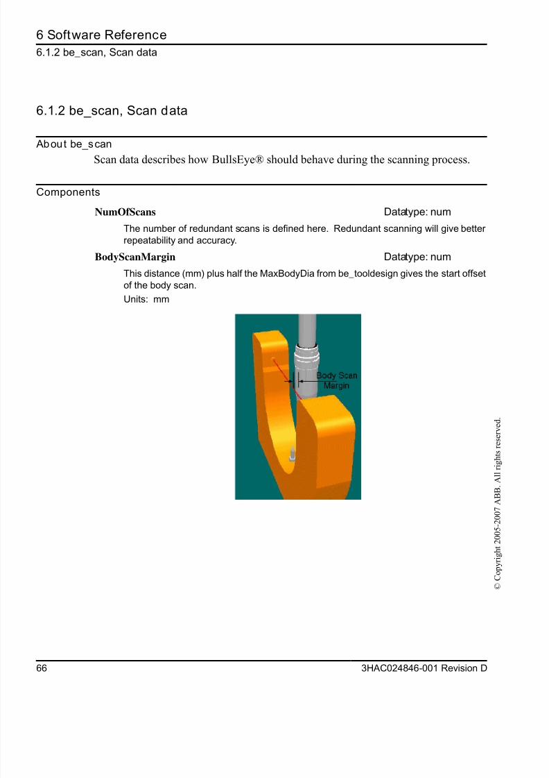
8/16/2019 Bullseye Manual RevD En
http://slidepdf.com/reader/full/bullseye-manual-revd-en 68/104
6 Software Reference
6.1.2 be_scan, Scan data
66 3HAC024846-001 Revision D
© C
o p y r i g h t 2 0 0 5 - 2 0 0 7 A B B .
A l l r i g h t s r e s e r v e d .
6.1.2 be_scan, Scan data
About be_scan
Scan data describes how BullsEye® should behave during the scanning process.
Components
NumOfScans Datatype: num
The number of redundant scans is defined here. Redundant scanning will give better
repeatability and accuracy.
BodyScanMargin Datatype: num
This distance (mm) plus half the MaxBodyDia from be_tooldesign gives the start offsetof the body scan.
Units: mm
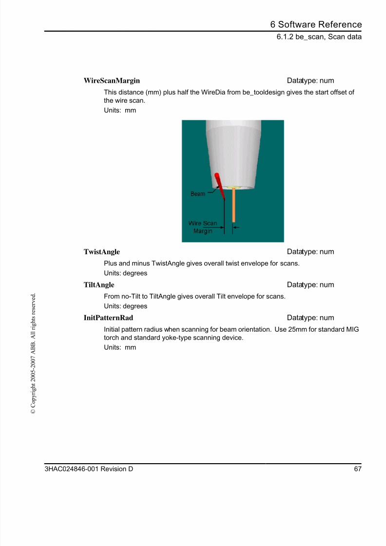
8/16/2019 Bullseye Manual RevD En
http://slidepdf.com/reader/full/bullseye-manual-revd-en 69/104
6 Software Referenc
6.1.2 be_scan, Scan dat
3HAC024846-001 Revision D 6
© C
o p y r i g h t 2 0 0 5 - 2 0 0 7 A B B .
A l l r i g h t s r e s e r v e d .
WireScanMargin Datatype: num
This distance (mm) plus half the WireDia from be_tooldesign gives the start offset ofthe wire scan.
Units: mm
TwistAngle Datatype: num
Plus and minus TwistAngle gives overall twist envelope for scans.
Units: degrees
TiltAngle Datatype: numFrom no-Tilt to TiltAngle gives overall Tilt envelope for scans.
Units: degrees
InitPatternRad Datatype: num
Initial pattern radius when scanning for beam orientation. Use 25mm for standard MIG
torch and standard yoke-type scanning device.
Units: mm
8/16/2019 Bullseye Manual RevD En
http://slidepdf.com/reader/full/bullseye-manual-revd-en 70/104
6 Software Reference
6.1.2 be_scan, Scan data
68 3HAC024846-001 Revision D
© C
o p y r i g h t 2 0 0 5 - 2 0 0 7 A B B .
A l l r i g h t s r e s e r v e d .
Structure
<dataobject of be_scan>
< NumOfScans of num>
< BodyScanMargin of num>
< WireScanMargin of num>
< TwistAngle of num>
< TiltAngle of num>
< InitPatternRad of num>
Related information
Described in:
BESetupToolJ Instructions on page 73
be_device Data Types on page 63
be_tooldesign Data Types on page 63
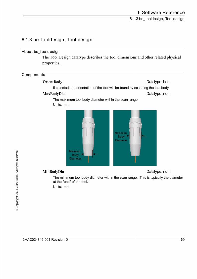
8/16/2019 Bullseye Manual RevD En
http://slidepdf.com/reader/full/bullseye-manual-revd-en 71/104
6 Software Referenc
6.1.3 be_tooldesign, Tool desig
3HAC024846-001 Revision D 6
© C
o p y r i g h t 2 0 0 5 - 2 0 0 7 A B B .
A l l r i g h t s r e s e r v e d .
6.1.3 be_tooldesign, Tool design
About be_too ldesign
The Tool Design datatype describes the tool dimensions and other related physical
properties.
Components
OrientBody Datatype: bool
If selected, the orientation of the tool will be found by scanning the tool body.
MaxBodyDia Datatype: num
The maximum tool body diameter within the scan range.
Units: mm
MinBodyDia Datatype: num
The minimum tool body diameter within the scan range. This is typically the diameteat the "end" of the tool.
Units: mm
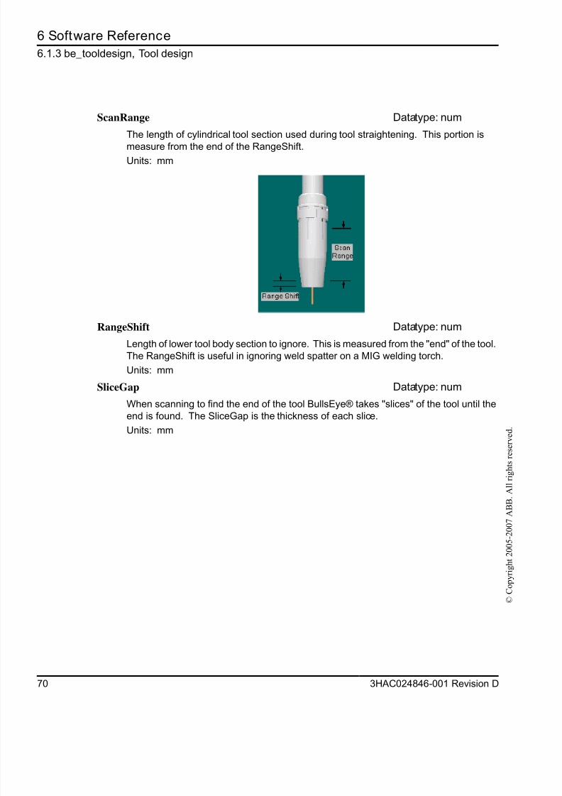
8/16/2019 Bullseye Manual RevD En
http://slidepdf.com/reader/full/bullseye-manual-revd-en 72/104
6 Software Reference
6.1.3 be_tooldesign, Tool design
70 3HAC024846-001 Revision D
© C
o p y r i g h t 2 0 0 5 - 2 0 0 7 A B B .
A l l r i g h t s r e s e r v e d .
ScanRange Datatype: num
The length of cylindrical tool section used during tool straightening. This portion ismeasure from the end of the RangeShift.
Units: mm
RangeShift Datatype: num
Length of lower tool body section to ignore. This is measured from the "end" of the tool.
The RangeShift is useful in ignoring weld spatter on a MIG welding torch.
Units: mm
SliceGap Datatype: num
When scanning to find the end of the tool BullsEye® takes "slices" of the tool until the
end is found. The SliceGap is the thickness of each slice.Units: mm
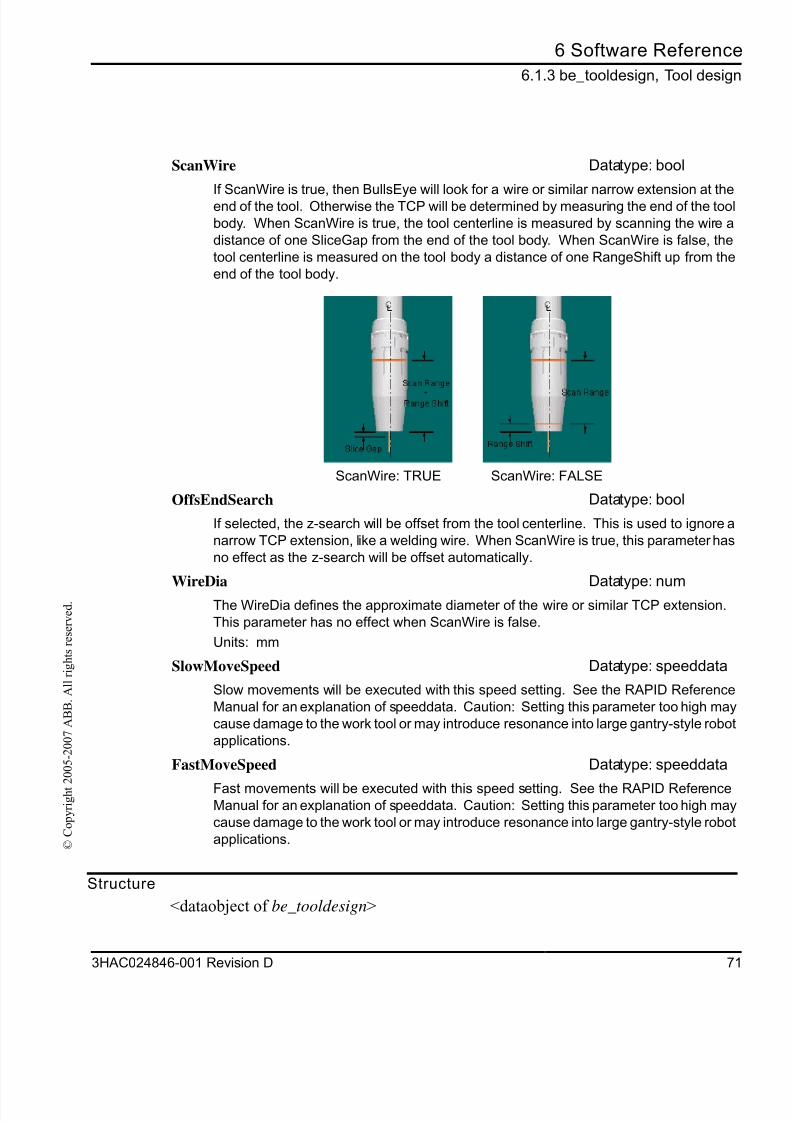
8/16/2019 Bullseye Manual RevD En
http://slidepdf.com/reader/full/bullseye-manual-revd-en 73/104
6 Software Referenc
6.1.3 be_tooldesign, Tool desig
3HAC024846-001 Revision D 7
© C
o p y r i g h t 2 0 0 5 - 2 0 0 7 A B B .
A l l r i g h t s r e s e r v e d .
Structure
<dataobject of be_tooldesign>
ScanWire Datatype: bool
If ScanWire is true, then BullsEye will look for a wire or similar narrow extension at theend of the tool. Otherwise the TCP will be determined by measuring the end of the too
body. When ScanWire is true, the tool centerline is measured by scanning the wire a
distance of one SliceGap from the end of the tool body. When ScanWire is false, the
tool centerline is measured on the tool body a distance of one RangeShift up from the
end of the tool body.
ScanWire: TRUE ScanWire: FALSE
OffsEndSearch Datatype: bool
If selected, the z-search will be offset from the tool centerline. This is used to ignore a
narrow TCP extension, like a welding wire. When ScanWire is true, this parameter has
no effect as the z-search will be offset automatically.
WireDia Datatype: numThe WireDia defines the approximate diameter of the wire or similar TCP extension.
This parameter has no effect when ScanWire is false.
Units: mm
SlowMoveSpeed Datatype: speeddata
Slow movements will be executed with this speed setting. See the RAPID Reference
Manual for an explanation of speeddata. Caution: Setting this parameter too high may
cause damage to the work tool or may introduce resonance into large gantry-style robo
applications.
FastMoveSpeed Datatype: speeddata
Fast movements will be executed with this speed setting. See the RAPID ReferenceManual for an explanation of speeddata. Caution: Setting this parameter too high may
cause damage to the work tool or may introduce resonance into large gantry-style robo
applications.
8/16/2019 Bullseye Manual RevD En
http://slidepdf.com/reader/full/bullseye-manual-revd-en 74/104
6 Software Reference
6.1.3 be_tooldesign, Tool design
72 3HAC024846-001 Revision D
© C
o p y r i g h t 2 0 0 5 - 2 0 0 7 A B B .
A l l r i g h t s r e s e r v e d .
< OrientBody of bool>
< MaxBodyDia of num>
< MinBodyDia of num>
<ScanRange of num>
< RangeShift of num>
<SliceGap of num>
<ScanWire of bool>
<OffsEndSearch of bool>
<WireDia of num>
<SlowMoveSpeed of speeddata>
<FastMoveSpeed of speeddata >
Related information
Described in:
BESetupToolJ Instructions on page 73
be_device Data Types on page 63be_scan Data Types on page 63
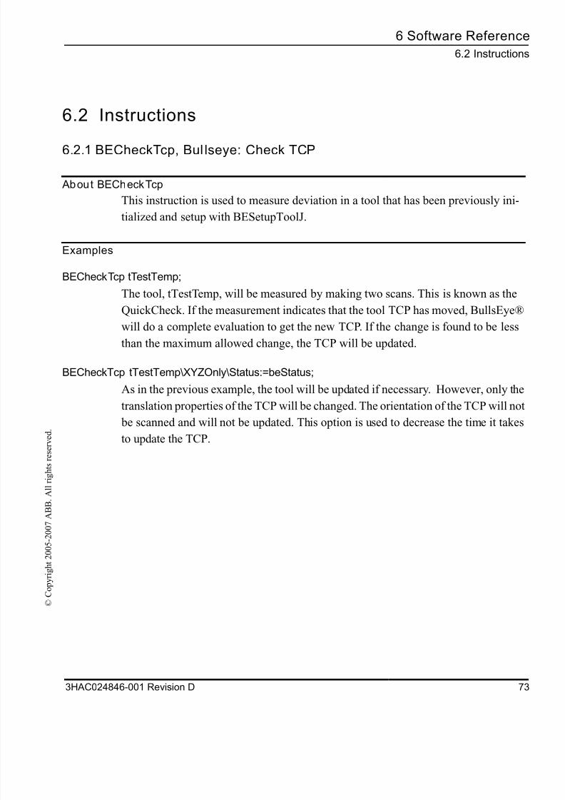
8/16/2019 Bullseye Manual RevD En
http://slidepdf.com/reader/full/bullseye-manual-revd-en 75/104
6 Software Referenc
6.2 Instruction
3HAC024846-001 Revision D 7
© C
o p y r i g h t 2 0 0 5 - 2 0 0 7 A B B .
A l l r i g h t s r e s e r v e d .
6.2 Instructions
6.2.1 BECheckTcp, Bul lseye: Check TCP
About BECheckTcp
This instruction is used to measure deviation in a tool that has been previously ini-
tialized and setup with BESetupToolJ.
Examples
BECheckTcp tTestTemp;The tool, tTestTemp, will be measured by making two scans. This is known as the
QuickCheck. If the measurement indicates that the tool TCP has moved, BullsEye®
will do a complete evaluation to get the new TCP. If the change is found to be less
than the maximum allowed change, the TCP will be updated.
BECheckTcp tTestTemp\XYZOnly\Status:=beStatus;
As in the previous example, the tool will be updated if necessary. However, only the
translation properties of the TCP will be changed. The orientation of the TCP will no
be scanned and will not be updated. This option is used to decrease the time it takesto update the TCP.
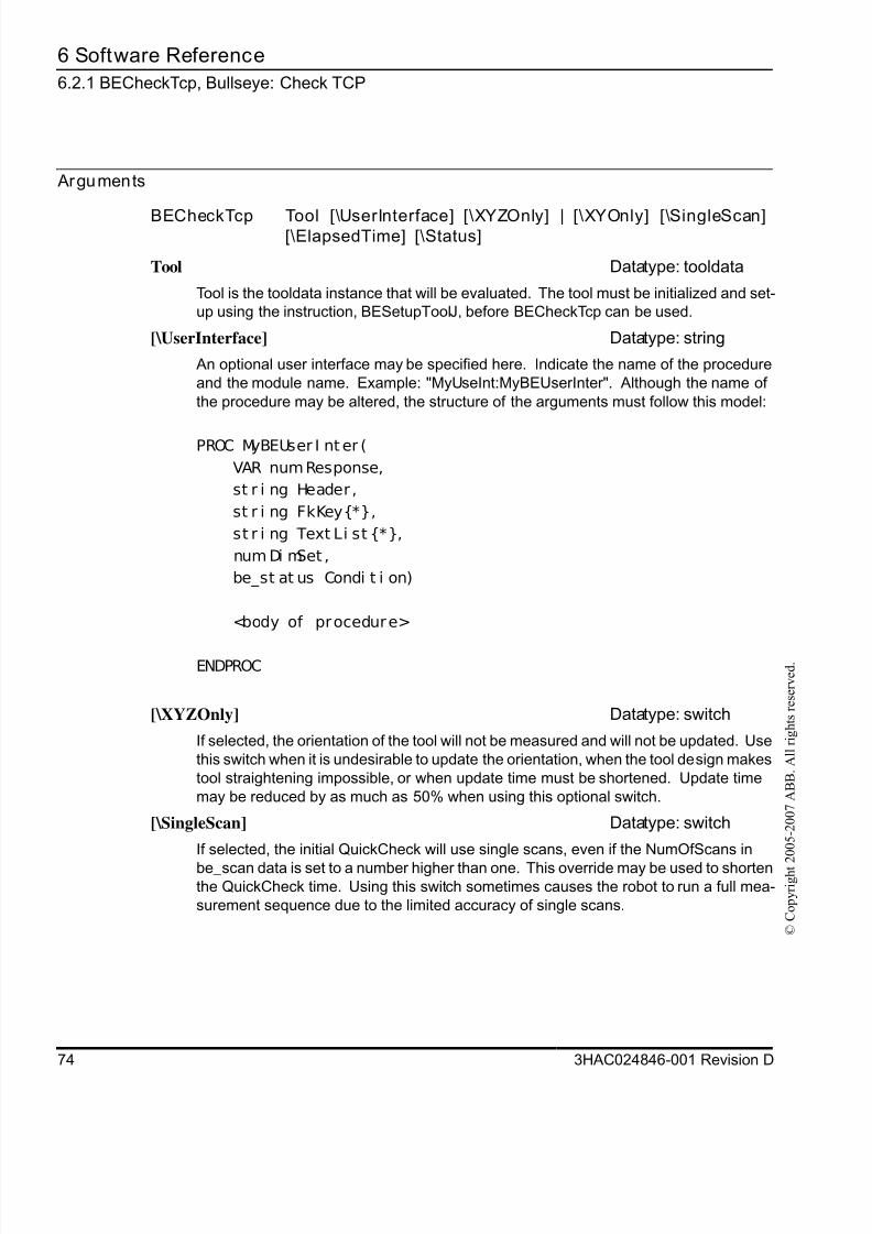
8/16/2019 Bullseye Manual RevD En
http://slidepdf.com/reader/full/bullseye-manual-revd-en 76/104
6 Software Reference
6.2.1 BECheckTcp, Bullseye: Check TCP
74 3HAC024846-001 Revision D
© C
o p y r i g h t 2 0 0 5 - 2 0 0 7 A B B .
A l l r i g h t s r e s e r v e d .
Arguments
BECheckTcp Tool [\UserInterface] [\XYZOnly] | [\XYOnly] [\SingleScan][\ElapsedTime] [\Status]
Tool Datatype: tooldata
Tool is the tooldata instance that will be evaluated. The tool must be initialized and set-up using the instruction, BESetupToolJ, before BECheckTcp can be used.
[\UserInterface] Datatype: string
An optional user interface may be specified here. Indicate the name of the procedure
and the module name. Example: "MyUseInt:MyBEUserInter". Although the name of
the procedure may be altered, the structure of the arguments must follow this model:
PROC MyBEUser I nter (
VAR numResponse,
st r i ng Header ,
st r i ng FkKey{*},
st r i ng Text Li st {*},
num Di mSet ,
be_st at us Condi t i on)
<body of procedure>
ENDPROC
[\XYZOnly] Datatype: switch
If selected, the orientation of the tool will not be measured and will not be updated. Use
this switch when it is undesirable to update the orientation, when the tool design makes
tool straightening impossible, or when update time must be shortened. Update time
may be reduced by as much as 50% when using this optional switch.
[\SingleScan] Datatype: switch
If selected, the initial QuickCheck will use single scans, even if the NumOfScans in
be_scan data is set to a number higher than one. This override may be used to shortenthe QuickCheck time. Using this switch sometimes causes the robot to run a full mea-
surement sequence due to the limited accuracy of single scans.
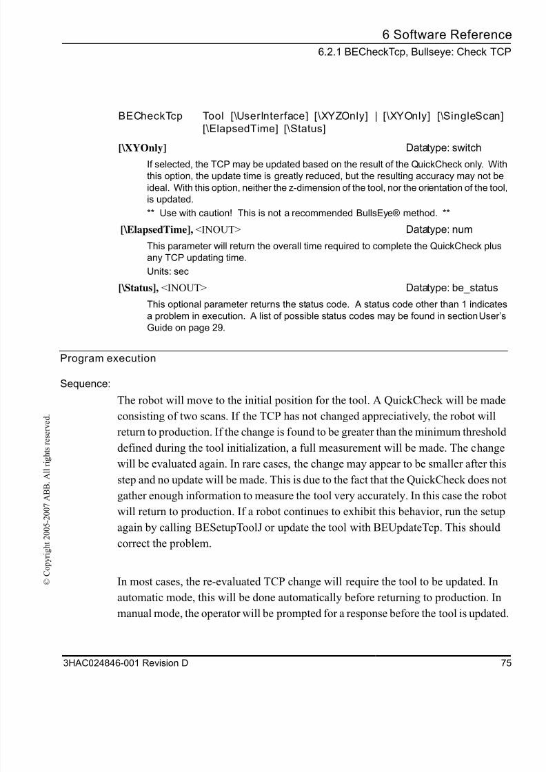
8/16/2019 Bullseye Manual RevD En
http://slidepdf.com/reader/full/bullseye-manual-revd-en 77/104
6 Software Referenc
6.2.1 BECheckTcp, Bullseye: Check TC
3HAC024846-001 Revision D 7
© C
o p y r i g h t 2 0 0 5 - 2 0 0 7 A B B .
A l l r i g h t s r e s e r v e d .
Program execution
Sequence:
The robot will move to the initial position for the tool. A QuickCheck will be madeconsisting of two scans. If the TCP has not changed appreciatively, the robot will
return to production. If the change is found to be greater than the minimum threshold
defined during the tool initialization, a full measurement will be made. The change
will be evaluated again. In rare cases, the change may appear to be smaller after this
step and no update will be made. This is due to the fact that the QuickCheck does not
gather enough information to measure the tool very accurately. In this case the robot
will return to production. If a robot continues to exhibit this behavior, run the setup
again by calling BESetupToolJ or update the tool with BEUpdateTcp. This should
correct the problem.
In most cases, the re-evaluated TCP change will require the tool to be updated. In
automatic mode, this will be done automatically before returning to production. In
manual mode, the operator will be prompted for a response before the tool is updated
[\XYOnly] Datatype: switch
If selected, the TCP may be updated based on the result of the QuickCheck only. With
this option, the update time is greatly reduced, but the resulting accuracy may not be
ideal. With this option, neither the z-dimension of the tool, nor the orientation of the toolis updated.
** Use with caution! This is not a recommended BullsEye® method. **
[\ElapsedTime], <INOUT> Datatype: num
This parameter will return the overall time required to complete the QuickCheck plus
any TCP updating time.
Units: sec
[\Status], <INOUT> Datatype: be_status
This optional parameter returns the status code. A status code other than 1 indicates
a problem in execution. A list of possible status codes may be found in section User’s
Guide on page 29.
BECheckTcp Tool [\UserInterface] [\XYZOnly] | [\XYOnly] [\SingleScan]
[\ElapsedTime] [\Status]
8/16/2019 Bullseye Manual RevD En
http://slidepdf.com/reader/full/bullseye-manual-revd-en 78/104
6 Software Reference
6.2.1 BECheckTcp, Bullseye: Check TCP
76 3HAC024846-001 Revision D
© C
o p y r i g h t 2 0 0 5 - 2 0 0 7 A B B .
A l l r i g h t s r e s e r v e d .
Execution in stepwise mode
Forward
Not supported.
Backward
Not supported.
Fault management
Known errors are raised as BullsEye® error codes in the optional argument, Status.
These codes may be handled outside the instruction with standard conditional state-
ments. BullsEye® error codes are not ERRNO constants handled in a RAPID error
handler.
Syntax
BECheckTcp
[ Tool ' : =' ] < expr essi on ( PERS) of t ool dat a >
[ ' \ ' User I nt er f ace ' : =' < expr essi on ( I N) of st r i ng > ]
[ ' \ ' XYZOnl y ] < swi t ch >
[ ' | ' XYOnl y ] < swi t ch >[ ' \ ' Si ngl eScan ] < swi t ch >
[ ' \ ' El apsedTi me ' : =' < expr essi on ( I NOUT) of num > ]
[ ' \ ' St at us ' : =' < expr essi on ( I NOUT) of be_st at us > ] ' ; '
Related information
Described in:
be_device Data Types on page 63
be_scan Data Types on page 63
be_tooldesign Data Types on page 63
BESetupToolJ Instructions on page 73
8/16/2019 Bullseye Manual RevD En
http://slidepdf.com/reader/full/bullseye-manual-revd-en 79/104
6 Software Referenc
6.2.2 BEDebugState, Debug State Contr
3HAC024846-001 Revision D 7
© C
o p y r i g h t 2 0 0 5 - 2 0 0 7 A B B .
A l l r i g h t s r e s e r v e d .
6.2.2 BEDebugState, Debug State Control
About BEDebugState
The BEDebugState instruction is used to control the debug log detail level. Normally
only limited information in stored in the BullsEye® log files. With this instruction,
more detailed information is recorded to help advanced users determine the cause of
an error.This instruction is hidden from the IPL.
Examples
BEDebugState\On;
Turns on the debugging flag.
BEDebugState\Off;
Turns off the debugging flag.
Arguments
Program execution
Sequence:
The instruction should be placed before BullsEye® instructions. The log files
affected are called BE_Oper.log and BE_Init.log and are found in the TEMP direc-tory of the robot.
BEDebugState [\On]
[\On] Datatype: switch
Used to turn on debugging.
[\Off] Datatype: switch
Used to turn off debugging.
8/16/2019 Bullseye Manual RevD En
http://slidepdf.com/reader/full/bullseye-manual-revd-en 80/104
6 Software Reference
6.2.2 BEDebugState, Debug State Control
78 3HAC024846-001 Revision D
© C
o p y r i g h t 2 0 0 5 - 2 0 0 7 A B B .
A l l r i g h t s r e s e r v e d .
Syntax
BEDebugState
[ ' \ ' On ] < swi t ch >
[ ' | ' Of f ] < swi t ch >
' ; '
Related information
Described in:
BECheckTcp Instructions on page 73
BESetupToolJ Instructions on page 73
BEUpdateTool Instructions on page 73
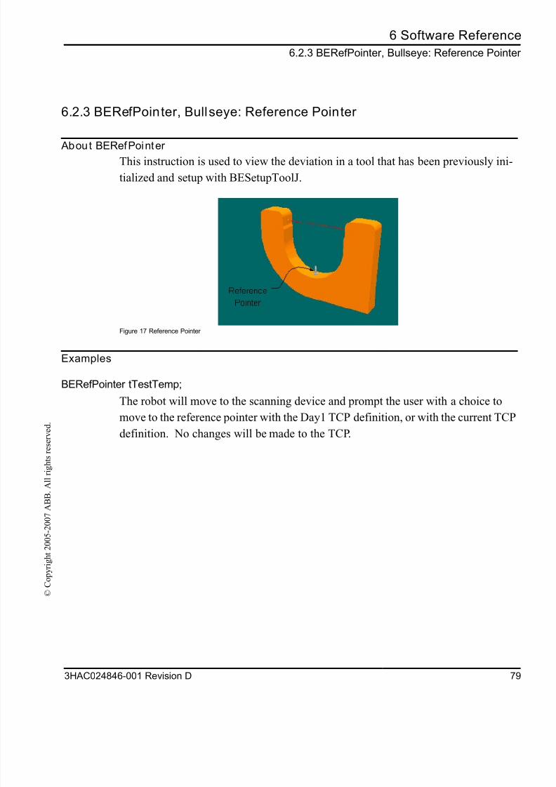
8/16/2019 Bullseye Manual RevD En
http://slidepdf.com/reader/full/bullseye-manual-revd-en 81/104
6 Software Referenc
6.2.3 BERefPointer, Bullseye: Reference Pointe
3HAC024846-001 Revision D 7
© C
o p y r i g h t 2 0 0 5 - 2 0 0 7 A B B .
A l l r i g h t s r e s e r v e d .
6.2.3 BERefPointer, Bullseye: Reference Pointer
About BERefPointer
This instruction is used to view the deviation in a tool that has been previously ini-
tialized and setup with BESetupToolJ.
Figure 17 Reference Pointer
Examples
BERefPointer tTestTemp;
The robot will move to the scanning device and prompt the user with a choice to
move to the reference pointer with the Day1 TCP definition, or with the current TCP
definition. No changes will be made to the TCP.
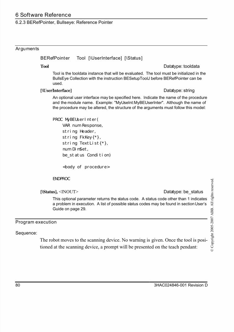
8/16/2019 Bullseye Manual RevD En
http://slidepdf.com/reader/full/bullseye-manual-revd-en 82/104
6 Software Reference
6.2.3 BERefPointer, Bullseye: Reference Pointer
80 3HAC024846-001 Revision D
© C
o p y r i g h t 2 0 0 5 - 2 0 0 7 A B B .
A l l r i g h t s r e s e r v e d .
Arguments
Program execution
Sequence:The robot moves to the scanning device. No warning is given. Once the tool is posi-
tioned at the scanning device, a prompt will be presented on the teach pendant:
BERefPointer Tool [\UserInterface] [\Status]
Tool Datatype: tooldata
Tool is the tooldata instance that will be evaluated. The tool must be initialized in the
BullsEye Collection with the instruction BESetupToolJ before BERefPointer can be
used.
[\UserInterface] Datatype: string
An optional user interface may be specified here. Indicate the name of the procedure
and the module name. Example: "MyUseInt:MyBEUserInter". Although the name of
the procedure may be altered, the structure of the arguments must follow this model:
PROC MyBEUser I nter (
VAR numResponse,
st r i ng Header ,
st r i ng FkKey{*},
st r i ng Text Li st {*},
num Di mSet ,
be_st at us Condi t i on)
<body of procedure>
ENDPROC
[\Status], <INOUT> Datatype: be_status
This optional parameter returns the status code. A status code other than 1 indicates
a problem in execution. A list of possible status codes may be found in section User’s
Guide on page 29.
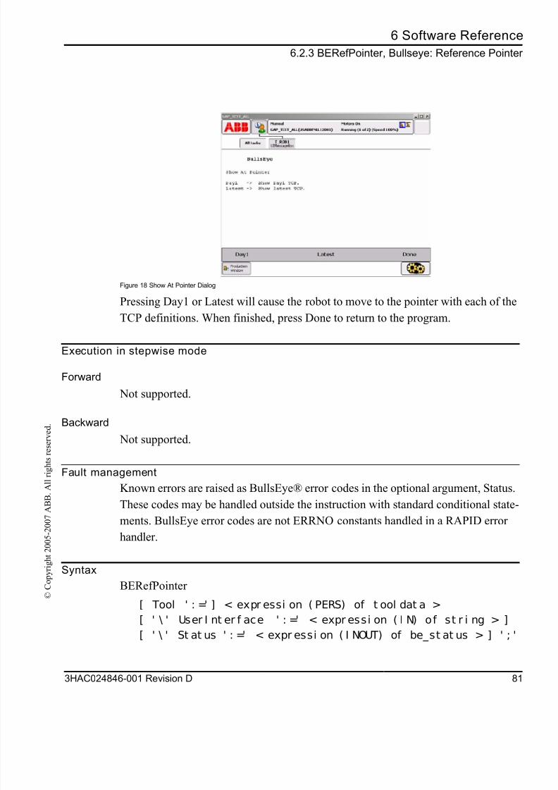
8/16/2019 Bullseye Manual RevD En
http://slidepdf.com/reader/full/bullseye-manual-revd-en 83/104
6 Software Referenc
6.2.3 BERefPointer, Bullseye: Reference Pointe
3HAC024846-001 Revision D 8
© C
o p y r i g h t 2 0 0 5 - 2 0 0 7 A B B .
A l l r i g h t s r e s e r v e d .
Figure 18 Show At Pointer Dialog
Pressing Day1 or Latest will cause the robot to move to the pointer with each of the
TCP definitions. When finished, press Done to return to the program.
Execution in stepwise mode
Forward
Not supported.
Backward
Not supported.
Fault management
Known errors are raised as BullsEye® error codes in the optional argument, Status.
These codes may be handled outside the instruction with standard conditional state
ments. BullsEye error codes are not ERRNO constants handled in a RAPID error
handler.
Syntax
BERefPointer
[ Tool ' : =' ] < expr essi on ( PERS) of t ool dat a >
[ ' \ ' User I nt er f ace ' : =' < expr essi on ( I N) of st r i ng > ]
[ ' \ ' St at us ' : =' < expr essi on ( I NOUT) of be_st at us > ] ' ; '

8/16/2019 Bullseye Manual RevD En
http://slidepdf.com/reader/full/bullseye-manual-revd-en 84/104
6 Software Reference
6.2.3 BERefPointer, Bullseye: Reference Pointer
82 3HAC024846-001 Revision D
© C
o p y r i g h t 2 0 0 5 - 2 0 0 7 A B B .
A l l r i g h t s r e s e r v e d .
Related information
Described in:
BESetupToolJ Instructions on page 73
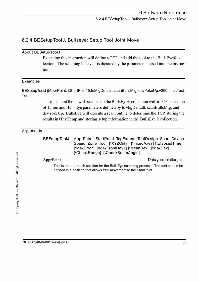
8/16/2019 Bullseye Manual RevD En
http://slidepdf.com/reader/full/bullseye-manual-revd-en 85/104
6 Software Referenc
6.2.4 BESetupToolJ, Bullseye: Setup Tool Joint Mov
3HAC024846-001 Revision D 8
© C
o p y r i g h t 2 0 0 5 - 2 0 0 7 A B B .
A l l r i g h t s r e s e r v e d .
6.2.4 BESetupToolJ, Bullseye: Setup Tool Joint Move
About BESetupToolJ
Executing this instruction will define a TCP and add the tool to the BullsEye® col-
lection. The scanning behavior is dictated by the parameters passed into the instruc
tion.
Examples
BESetupToolJ jtApprPoint, jtStartPos,15,tdMigDefault,scanBullsMig, devYokeUp,v200,fine,tTest
Temp;
The tool, tTestTemp, will be added to the BullsEye® collection with a TCP extension
of 15mm and BullsEye parameters defined by tdMigDefault, scanBullsMig, and
devYokeUp. BullsEye will execute a scan routine to determine the TCP, storing the
results in tTestTemp and storing setup information in the BullsEye® collection.
Arguments
BESetupToolJ ApprPoint StartPoint TcpExtens ToolDesign Scan Device
Speed Zone Tool [\XYZOnly] [\FixedAxes] [\ElapsedTime]
[\MaxError ] [\MaxFromDay1] [\MeanDev] [\MaxDev][\CheckRange] [\CheckBeamAngle]
ApprPoint Datatype: jointtarget
This is the approach position for the BullsEye scanning process. The tool should be
defined in a position that allows free movement to the StartPoint.
8/16/2019 Bullseye Manual RevD En
http://slidepdf.com/reader/full/bullseye-manual-revd-en 86/104
6 Software Reference
6.2.4 BESetupToolJ, Bullseye: Setup Tool Joint Move
84 3HAC024846-001 Revision D
© C
o p y r i g h t 2 0 0 5 - 2 0 0 7 A B B .
A l l r i g h t s r e s e r v e d .
StartPoint Datatype: jointtarget
This is the start position for the BullsEye scanning process. The tool should be posi-
tioned so that the tool center pointer (TCP) is located on the scan beam near its center.
The tool should be oriented so that the tool is perpendicular to the scanning device's
scan plane.
TcpExtens Datatype: num
The length of the TCP extension, as measured from the end of the tool body, is defined
here in millimeters.
Units: mm
ToolDesign Datatype: be_tooldesign
The Tool Design datatype describes the tool dimensions and other physical properties.
Scan Datatype: be_scan
BESetupToolJ ApprPoint StartPoint TcpExtens ToolDesign Scan Device
Speed Zone Tool [\XYZOnly] [\FixedAxes] [\ElapsedTime]
[\MaxError ] [\MaxFromDay1] [\MeanDev] [\MaxDev]
[\CheckRange] [\CheckBeamAngle]
8/16/2019 Bullseye Manual RevD En
http://slidepdf.com/reader/full/bullseye-manual-revd-en 87/104
6 Software Referenc
6.2.4 BESetupToolJ, Bullseye: Setup Tool Joint Mov
3HAC024846-001 Revision D 8
© C
o p y r i g h t 2 0 0 5 - 2 0 0 7 A B B .
A l l r i g h t s r e s e r v e d .
Scan data describes how BullsEye should behave during the scanning process.
Device Datatype: be_device
This data structure contains parameters that are used to describe the scanning device's
properties.
Speed Datatype: speeddata
The speed the TCP will move to the ApprPoint. See the RAPID Reference Manual fo
an explanation of speeddata.
Zone Datatype: zonedata
The zone applied to the movement to ApprPoint. See the RAPID Reference Manual
for an explanation of zonedata.
Tool Datatype: tooldata
Tool is the tooldata instance that is to be added to the BullsEye collection.
[\XYZOnly] Datatype: switch
When selected, BullsEye will not attempt to find the orientation of the tool. Doing so wil
speed up the setup process, however variation in the tool orientation will not be
detected.
[\FixedAxes] Datatype: be_fixedaxe
If the robot is moved by a multi-axis mechanical unit and the scanning device is
mounted on one of links of this mechanical unit, other than the final link, this argumen
must be used. The structure consists of six Boolean flags representing each of the six
possible external axes. If an axis must be in a certain position to maintain the robot-to
scan-device relationship, then the flag for that axis should be set to TRUE. For exam
ple, if the robot is mounted on a rotating tower with linear carriage movement on the
boom, then it is possible that the BullsEye scanning device could be mounted to the
first link, and the robot mounted to the second link. In this case, it is necessary to se
the FixedAxes flag corresponding to the linear axis to TRUE, because this axis must be
driven to a designated position to fix the relationship between the scanning device andthe robot.
BESetupToolJ ApprPoint StartPoint TcpExtens ToolDesign Scan Device
Speed Zone Tool [\XYZOnly] [\FixedAxes] [\ElapsedTime]
[\MaxError ] [\MaxFromDay1] [\MeanDev] [\MaxDev]
[\CheckRange] [\CheckBeamAngle]
8/16/2019 Bullseye Manual RevD En
http://slidepdf.com/reader/full/bullseye-manual-revd-en 88/104
6 Software Reference
6.2.4 BESetupToolJ, Bullseye: Setup Tool Joint Move
86 3HAC024846-001 Revision D
© C
o p y r i g h t 2 0 0 5 - 2 0 0 7 A B B .
A l l r i g h t s r e s e r v e d .
[\ElapsedTime], <INOUT> Datatype: num
This parameter will return the overall time required to complete the setup.
Units: sec
[\MaxError], <INOUT> Datatype: num
MaxError is the distance in millimeters that the TCP is allowed to deviate before Quick-
Check will indicate the change. When not selected, MaxError will be set to four times
the Repeatability found in the be_device data.
Units: mm
[\MaxFromDay1], <INOUT> Datatype: num
If the TCP is found to be more than the distance, MaxFromDay1, the tool will need to
be set-up again. The default is 5mm when not selected.
Units: mm
[\MeanDev], <INOUT> Datatype: num
BullsEye uses four scan orientations to determine the TCP. Some deviation between
measurements is normal, but excessive deviation suggests that the robot may be cali-
brated incorrectly, or the tool or TCP extension may be loose. This parameter may be
queried to evaluate the accuracy of the TCP after the setup is complete.
Units: mm
[\MaxDev], <INOUT> Datatype: num
This parameter may be used in conjunction with MeanDev to evaluate the accuracy of
the TCP after the setup is complete.
Units: mm
[\CheckRange] Datatype: switch
If selected, the robot will make a series of moves to approximate the motion of the robot
arm during the scan sequence. This argument may only be used when the supplied
tool includes values that are approximately correct. This setting can be useful in deter-
mining where to mount the BullsEye sensor. This argument is used in conjunction withCheckBeamAngle.
[\CheckBeamAngle] Datatype: num
This argument is used to provide the orientation of the BullsEye beam relative to the
base of the robot. BullsEye assumes that the sensing beam is parallel to the plane of
the robot base. This value determines how the beam is oriented in that plane. The
CheckRange argument must be used in conjunction with this argument.
BESetupToolJ ApprPoint StartPoint TcpExtens ToolDesign Scan Device
Speed Zone Tool [\XYZOnly] [\FixedAxes] [\ElapsedTime]
[\MaxError ] [\MaxFromDay1] [\MeanDev] [\MaxDev]
[\CheckRange] [\CheckBeamAngle]
8/16/2019 Bullseye Manual RevD En
http://slidepdf.com/reader/full/bullseye-manual-revd-en 89/104
6 Software Referenc
6.2.4 BESetupToolJ, Bullseye: Setup Tool Joint Mov
3HAC024846-001 Revision D 8
© C
o p y r i g h t 2 0 0 5 - 2 0 0 7 A B B .
A l l r i g h t s r e s e r v e d .
Program execution
Sequence:
The tool is added to the BullsEye® Collection along with all of the data that is passed
into the instruction. BullsEye® will then perform a scan sequence to determine the
TCP of the tool.
Execution in stepwise mode
Forward
In forward step mode, the robot will stop at the approach point. Hitting forward step
again will advance the robot to the start point and start the scanning routine.
Backward
Not supported.
Fault management
Known errors are raised as BullsEye error codes in the optional argument, Status.
These codes may be handled outside the instruction with standard conditional state
ments. BullsEye error codes are not ERRNO constants handled in a RAPID errorhandler.
Syntax
BESetupToolJ
[ Appr Poi nt ' : =' ] < expr essi on ( IN) of j oi nt t ar get > ' , '
[ St ar t Poi nt ' : =' ] < expr essi on ( IN) of j oi nt t arget > ' , '
[ TcpExt ens ' : =' ] < expr essi on ( IN) of num >
[ Tool Desi gn ' : =' ] < expr essi on ( IN) of be_t ool desi gn > ' , '
[ Scan ' : =' ] < expr essi on ( IN) of be_scan > ' , '[ Devi ce ' : =' ] < expr essi on ( IN) of be_devi ce >
[ Speed ' : =' ] < expr essi on ( IN) of speeddat a > ' , '
[ Zone ' : =' ] < expr essi on ( IN) of zonedat a > ' , '
[ Tool ' : =' ] < expr essi on ( PERS) of t ool dat a > ' , '
[ ' \ ' XYZOnl y ] < swi t ch >
8/16/2019 Bullseye Manual RevD En
http://slidepdf.com/reader/full/bullseye-manual-revd-en 90/104
6 Software Reference
6.2.4 BESetupToolJ, Bullseye: Setup Tool Joint Move
88 3HAC024846-001 Revision D
© C
o p y r i g h t 2 0 0 5 - 2 0 0 7 A B B .
A l l r i g h t s r e s e r v e d .
[ ' \ ' Fi xedAxes ' : =' < expr essi on ( IN) of be_f i xedaxes > ]
[ ' \ ' MaxEr r or ' : =' < expr essi on ( I N) of num > ]
[ ' \ ' MaxFr omDay1 ' : =' < expr essi on ( I N) of num > ]
[ ' \ ' El apsedTi me ' : =' < expr essi on ( INOUT) of num > ]
[ ' \ ' MeanDev ' : =' < expr essi on ( INOUT) of num > ]
[ ' \ ' MaxDev ' : =' < expr essi on ( INOUT) of num > ]
[ ' \ ' CheckRange ] < swi t ch >
[ ' \ ' CheckBeamAngl e ' : =' <expr essi on ( IN) of num > ] ' ; '
Related information
Described in:
be_device Data Types on page 63
be_scan Data Types on page 63
be_tooldesign Data Types on page 63
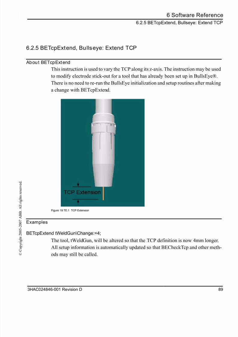
8/16/2019 Bullseye Manual RevD En
http://slidepdf.com/reader/full/bullseye-manual-revd-en 91/104
6 Software Referenc
6.2.5 BETcpExtend, Bullseye: Extend TC
3HAC024846-001 Revision D 8
© C
o p y r i g h t 2 0 0 5 - 2 0 0 7 A B B .
A l l r i g h t s r e s e r v e d .
6.2.5 BETcpExtend, Bullseye: Extend TCP
About BETcpExtend
This instruction is used to vary the TCP along its z-axis. The instruction may be used
to modify electrode stick-out for a tool that has already been set up in BullsEye®.
There is no need to re-run the BullsEye initialization and setup routines after making
a change with BETcpExtend.
Figure 19 TE.1 TCP Extension
Examples
BETcpExtend tWeldGun\Change:=4;
The tool, tWeldGun, will be altered so that the TCP definition is now 4mm longer.
All setup information is automatically updated so that BECheckTcp and other meth
ods may still be called.
8/16/2019 Bullseye Manual RevD En
http://slidepdf.com/reader/full/bullseye-manual-revd-en 92/104
6 Software Reference
6.2.5 BETcpExtend, Bullseye: Extend TCP
90 3HAC024846-001 Revision D
© C
o p y r i g h t 2 0 0 5 - 2 0 0 7 A B B .
A l l r i g h t s r e s e r v e d .
Arguments
Program execution
Sequence:This instruction does not cause robot motion. All data is converted if successful.
Otherwise, no data is converted.
Execution in stepwise mode
Forward
Same as continuous.
Backward Not supported.
Fault management
Known errors are raised as BullsEye error codes in the optional argument, Status.
These codes may be handled outside the instruction with standard conditional state-
BETcpExtend Tool [\Change] | [\Absolute] [\NewExtens] [\Status]
Tool <PERS> Datatype: tooldata
Tool is the tooldata instance that will be modified. The tool must be set-up using the
instruction, BESetupToolJ, before BETcpExtend can be used.
[\Change] Datatype: num
This is the amount that the TCP will be extended along its z-axis.
[\Absolute] Datatype: num
This is the absolute TCP extension that is requested.
[\NewExtens] <INOUT> Datatype: num
Returns the value of the new TCP extension. This is useful when using the Change
argument to get the resulting TCP extension.
[\Status] <INOUT> Datatype: be_status
This optional parameter returns the status code. A status code other than 1 indicates a
problem in execution. A list of possible status codes may be found in section User’s
Guide on page 29.
8/16/2019 Bullseye Manual RevD En
http://slidepdf.com/reader/full/bullseye-manual-revd-en 93/104
6 Software Referenc
6.2.5 BETcpExtend, Bullseye: Extend TC
3HAC024846-001 Revision D 9
© C
o p y r i g h t 2 0 0 5 - 2 0 0 7 A B B .
A l l r i g h t s r e s e r v e d .
ments. BullsEye error codes are not ERRNO constants handled in a RAPID error
handler.
Syntax
BETcpExtend
[ Tool ' : =' ] < expr essi on ( PERS) of t ool dat a >
[ ' \ ' Change ' : =' < expr essi on ( I N) of num > ]
| [ ' \ ' Absol ut e ' : =' < expr essi on ( I N) of num > ]
[ ' \ ' NewExtens ' : =' < expr essi on ( I NOUT) of num > ]
[ ' \ ' St at us ' : =' < expr essi on ( I NOUT) of be_st at us > ] ' ; '
Related information
Described in:
BESetupToolJ Instructions on page 73
8/16/2019 Bullseye Manual RevD En
http://slidepdf.com/reader/full/bullseye-manual-revd-en 94/104
6 Software Reference
6.2.6 BEUpdateTcp, Bullseye: Update TCP
92 3HAC024846-001 Revision D
© C
o p y r i g h t 2 0 0 5 - 2 0 0 7 A B B .
A l l r i g h t s r e s e r v e d .
6.2.6 BEUpdateTcp, Bullseye: Update TCP
About BEUpdateTcp
Running this instruction measures and updates the TCP of a tool that has been previ-
ously initialized and setup with BESetupToolJ.
Examples
BEUpdateTcp tTestTemp;
The tool, tTestTemp, will be measured by making a full set of scans, including scans
to update the tool orientation.
BEUpdateTcp tTestTemp\XYZOnly\Status:=beStatus;
As in the previous example, the translational dimensions of the TCP will be updated.
The orientation of the TCP, however, will not be scanned and will not be updated.
This option is used to decrease the time it takes to update the TCP. The Status
optional argument provides status codes after the instruction is run.
8/16/2019 Bullseye Manual RevD En
http://slidepdf.com/reader/full/bullseye-manual-revd-en 95/104
6 Software Referenc
6.2.6 BEUpdateTcp, Bullseye: Update TC
3HAC024846-001 Revision D 9
© C
o p y r i g h t 2 0 0 5 - 2 0 0 7 A B B .
A l l r i g h t s r e s e r v e d .
Arguments
BEUpdateTcp Tool [\UserInterface] [\XYZOnly] [\ElapsedTime] [\Status]
Tool Datatype: tooldata
Tool is the tooldata instance that will be evaluated. The tool must be initialized and
setup with the instruction, BESetupToolJ, before BEUpdateTcp can be used.
[\UserInterface] Datatype: string
An optional user interface may be specified here. Indicate the name of the procedure
and the module name. Example: "MyUseInt:MyBEUserInter". Although the name of the
procedure may be altered, the structure of the arguments must follow this model:
PROC MyBEUser I nter (
VAR numResponse, st r i ng Header ,
st r i ng FkKey{*},
st r i ng Text Li st {*},
num Di mSet ,
be_st at us Condi t i on)
<body of procedure>
ENDPROC
[\XYZOnly] Datatype: switch
If selected, the orientation of the tool will not be measured and will not be updated. Use
this switch when it is undesirable to update the orientation, when the tool design makes
tool straightening impossible, or when update time must be shortened. Update time
may be reduced by as much as 50% when using this optional switch.
[\ElapsedTime] <INOUT> Datatype: num
This parameter will return the overall time required to complete the QuickCheck plus
any TCP updating time.
Units: sec
[\Status] <INOUT> Datatype: be_status
This optional parameter returns the status code. A status code other than 1 indicates a
problem in execution. A list of possible status codes may be found in section User’s
Guide on page 29.
8/16/2019 Bullseye Manual RevD En
http://slidepdf.com/reader/full/bullseye-manual-revd-en 96/104
6 Software Reference
6.2.6 BEUpdateTcp, Bullseye: Update TCP
94 3HAC024846-001 Revision D
© C
o p y r i g h t 2 0 0 5 - 2 0 0 7 A B B .
A l l r i g h t s r e s e r v e d .
Program execution
Sequence:
The robot will move to the initial position for the tool. A full measurement will be
made and the tool will be updated.
Execution in stepwise mode
Forward
Not supported.
Backward
Not supported.
Fault management
Known errors are raised as BullsEye error codes in the optional argument, Status.
These codes may be handled outside the instruction with standard conditional state-
ments. BullsEye error codes are not ERRNO constants handled in a RAPID error
handler.
Syntax
BEUpdateTcp
[ Tool ' : =' ] < expr essi on ( PERS) of t ool dat a >
[ ' \ ' User I nt er f ace ' : =' < expr essi on ( I N) of st r i ng > ]
[ ' \ ' XYZOnl y ] < swi t ch >
[ ' \ ' El apsedTi me ' : =' < expr essi on ( I NOUT) of num > ]
[ ' \ ' St at us ' : =' < expr essi on ( I NOUT) of be_st at us > ] ' ; '
Related information
Described in:
be_device Data Types on page 63
be_scan Data Types on page 63
8/16/2019 Bullseye Manual RevD En
http://slidepdf.com/reader/full/bullseye-manual-revd-en 97/104
6 Software Referenc
6.2.6 BEUpdateTcp, Bullseye: Update TC
3HAC024846-001 Revision D 9
© C
o p y r i g h t 2 0 0 5 - 2 0 0 7 A B B .
A l l r i g h t s r e s e r v e d .
be_tooldesign Data Types on page 63
BESetupToolJ Instructions on page 73
Described in:

8/16/2019 Bullseye Manual RevD En
http://slidepdf.com/reader/full/bullseye-manual-revd-en 98/104
6 Software Reference
6.2.6 BEUpdateTcp, Bullseye: Update TCP
96 3HAC024846-001 Revision D
© C
o p y r i g h t 2 0 0 5 - 2 0 0 7 A B B .
A l l r i g h t s r e s e r v e d .
8/16/2019 Bullseye Manual RevD En
http://slidepdf.com/reader/full/bullseye-manual-revd-en 99/104
6 Software Referenc
6.3 Function
3HAC024846-001 Revision D 9
© C
o p y r i g h t 2 0 0 5 - 2 0 0 7 A B B .
A l l r i g h t s r e s e r v e d .
6.3 Functions
6.3.1 OffsToolXYZ, Offsets Tool - Cartesian
About OffsToolXYZ
OffsToolXYZ is a function that requires a tooldata instance and an offset as pos data.
The function will return a new tooldata value offset in tool coordinates by the amoun
specified by the pos offset.
Examples
CONST pos psMyOf f set : = [ 1, 2, 3] ;
t MyOf f set Tool : =Of f sTool XYZ ( t MyOr i gi nal Tool , psMyOf f set ) ;
The tool is offset 1mm in X, 2mm in Y, and 3mm in Z, relative to the tool coordinates
Return value
Arguments
Datatype: tooldataThe new TCP data.
OffsToolXYZ ( Tool Offset )
Tool Datatype: tooldata
Original tool.
[Offset] Datatype: pos
Offset in mm.
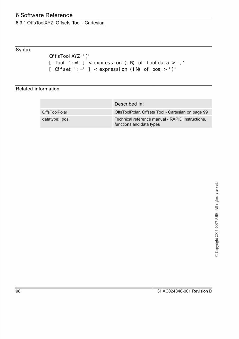
8/16/2019 Bullseye Manual RevD En
http://slidepdf.com/reader/full/bullseye-manual-revd-en 100/104
6 Software Reference
6.3.1 OffsToolXYZ, Offsets Tool - Cartesian
98 3HAC024846-001 Revision D
© C
o p y r i g h t 2 0 0 5 - 2 0 0 7 A B B .
A l l r i g h t s r e s e r v e d .
Syntax
Of f sTool XYZ ' ( '
[ Tool ' : =' ] < expr essi on ( I N) of t ool dat a > ' , '
[ Of f set ' : =' ] < expr essi on ( I N) of pos > ' ) '
Related information
Described in:
OffsToolPolar OffsToolPolar, Offsets Tool - Cartesian on page 99
datatype: pos Technical reference manual - RAPID Instructions,functions and data types
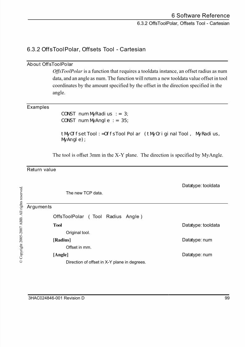
8/16/2019 Bullseye Manual RevD En
http://slidepdf.com/reader/full/bullseye-manual-revd-en 101/104
6 Software Referenc
6.3.2 OffsToolPolar, Offsets Tool - Cartesia
3HAC024846-001 Revision D 9
© C
o p y r i g h t 2 0 0 5 - 2 0 0 7 A B B .
A l l r i g h t s r e s e r v e d .
6.3.2 OffsToolPolar, Offsets Tool - Cartesian
About OffsToolPolar
OffsToolPolar is a function that requires a tooldata instance, an offset radius as num
data, and an angle as num. The function will return a new tooldata value offset in tool
coordinates by the amount specified by the offset in the direction specified in the
angle.
Examples
CONST num MyRadi us : = 3;
CONST num MyAngl e : = 35;
t MyOf f set Tool : =Of f sTool Pol ar ( t MyOr i gi nal Tool , MyRadi us,MyAngl e) ;
The tool is offset 3mm in the X-Y plane. The direction is specified by MyAngle.
Return value
Arguments
Datatype: tooldata
The new TCP data.
OffsToolPolar ( Tool Radius Angle )
Tool Datatype: tooldata
Original tool.
[Radius] Datatype: num
Offset in mm.
[Angle] Datatype: num
Direction of offset in X-Y plane in degrees.
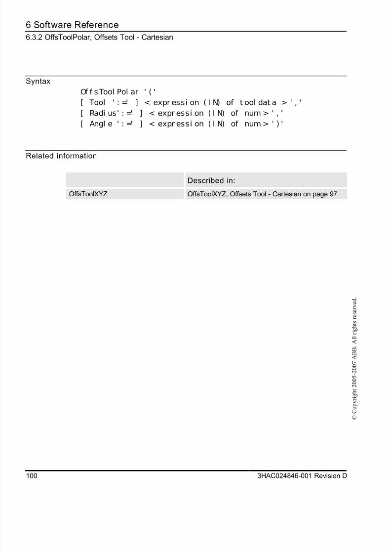
8/16/2019 Bullseye Manual RevD En
http://slidepdf.com/reader/full/bullseye-manual-revd-en 102/104
6 Software Reference
6.3.2 OffsToolPolar, Offsets Tool - Cartesian
100 3HAC024846-001 Revision D
© C
o p y r i g h t 2 0 0 5 - 2 0 0 7 A B B .
A l l r i g h t s r e s e r v e d .
Syntax
Of f sTool Pol ar ' ( '
[ Tool ' : =' ] < expr essi on ( I N) of t ool dat a > ' , '
[ Radi us' : =' ] < expr essi on ( I N) of num > ' , '
[ Angl e ' : =' ] < expr essi on ( I N) of num > ' ) '
Related information
Described in:
OffsToolXYZ OffsToolXYZ, Offsets Tool - Cartesian on page 97

8/16/2019 Bullseye Manual RevD En
http://slidepdf.com/reader/full/bullseye-manual-revd-en 103/104

8/16/2019 Bullseye Manual RevD En
http://slidepdf.com/reader/full/bullseye-manual-revd-en 104/104
C 0 2 4 8 4 6 - 0 0 1 ,
R e v i s i o n D , e n