bull dps 7000
TRANSCRIPT

Hardware
Bull DPS 7000
CDA 7 5630 Product Manual
77 A1 69UP Rev00

77 A1 69UP Rev00
Hardware
Bull DPS 7000
CDA 7 5630 Product Manual
Subject: This manual describes the features and operations of theCDA 7 5630.
Note that the CDA 7 former references have their own ProductManual
Special Instructions:
Software Supported: GCOS 7-V7 TS 7560 and later
GCOS 7-V8 TS 8560 and later
GCOS 7-V9 TS 9662 and later
Software/Hardware required:
Date: September 1999
Bull S.A.CEDOCAtelier de reprographie34, rue du Nid de Pie BP 42849004 ANGERS Cedex 01FRANCE
Bull HN Information Systems Inc.Publication Order EntryFAX: (978) 294-7411MA30/865ATechnology ParkBillerica, MA 01821U.S.A.

77 A1 69UP Rev00
Copyright © Bull S.A., 1999
Bull acknowledges the rights of proprietors of trademarks mentioned herein.
Your suggestions and criticisms concerning the form, contents and presentation of this manual are invited.A form is provided at the end of this manual for this purpose.
No part of this publication may be reproduced, stored in a retrieval system or transmitted in any form or by anymeans, electronic, mechanical or otherwise without the prior written permission of the publisher.
Bull disclaims the implied warranties of merchantability and fitness for a particular purpose and makes noexpress warranties except as may be stated in its written agreement with and for its customer. In no event is Bullliable to anyone for any indirect, special, or consequential damages.The information and specifications in this document are subject to change without notice.Consult your Bull Marketing Representative for product or service availability.

77 A1 69UP Rev00 iii
Preface
The CDA 7 subsystem is a very reliable high performance Integrated Cached DiskArray (ICDA) designed for online data storage. The CDA 7 houses both controllerand data storage capabilities in a single cabinet.
As part of its effort to continuously improve and enhance the performance andcapabilities of the Bull product line, Bull from time to time releases new revisionsof CDA 7 5630 hardware and microcode. Therefore, some functions described inthis manual may not be supported by all revision of CDA 7 microcode or hardwarepresently in use.
The document concerns the CDA 7 5630 product, which will be called CDA 7 inthe rest of the document.
Where to Get Help
To obtain technical support for your CDA 7 5630, call your local Bull CompetenceCenter.
This manual is part of the documentation set for the CDA 7 5630 product.
This manual describes the CDA 7 5630 features and operations.
CAUTION:The CDA 7 5630 contains no user-serviceable parts, so it should not beopened for any reason by untrained persons. If the CDA 7 is in need ofrepair, only qualified personnel familiar with safety procedures forelectrical equipment and the CDA 7 should access components inside theunit.
This manual is intended for the storage administrator, system programmer, oroperator who is involved in acquiring, managing, or operating the CDA 7subsystem.
Scope andObjectives
IntendedReaders

CDA 7 5630 Product Manual
iv 77 A1 69UP Rev00
For GCOS 7 systems, the CDA 7 subsystem is available with two disk technologiesgiving two different disk capacities: 18 GB and 36 GB.
18 GB refers to the formatted disk capacity. This is equivalent to an unformatteddisk capacity of 23 GB.
36 GB refers to the formatted disk capacity. This is equivalent to an unformatteddisk capacity of 47 GB.
This manual is structured as follows:
Chapter 1 Introducing CDA 7 provides an overview of theCDA 7 5630, highlighting its performance andreliability features, and describes hardware andsoftware options for the unit.
Chapter 2 CDA 7 Hardware introduces the hardwarecomponents of the CDA 7 5630. It describes its maincomponents, the function of the operator panel, and thetypes of host channels and devices to which CDA 7can attach.
Chapter 3 CDA 7 Input/Output Operations discussesintegrated cached disk arrays, I/O operation, and cachemanagement.
Chapter 4 Performance Features describes the CDA 7 performance features, how they will affect overallperformance, and how to use these features to get thebest performance from CDA 7.
Chapter 5 Managing Critical Data discusses the CDA 7 featuresthat affect data availability and reliability.
Appendix A Power Sequences provides step-by-step instructionsfor powering the CDA 7 5630 on and off.
Appendix B EPS Installation Requirements covers the tasks youneed to perform when planning or verifying thephysical configuration of CDA 7 in your system orcreating I/O addressing schemes.
Glossary defines terms used in this manual.
Index contains an index to help you access the information ofinterest directly.
Prerequisites
Structure
Preface
77 A1 69UP Rev00 v
Other EMC publications include:
Symmetrix Enterprise Storage Platform Product Guide...................................................................... P/N 200-999-556, EMC CorporationSymmetrix Open Systems Host Environment Product Guide, Volumes I and II...................................................................... P/N 200-999-563, EMC CorporationSymmetrix Remote Data Facility Product GuideP/N 200-999-554, EMC CorporationSRDF Host Component Product Guide........... P/N 200-999-561, EMC CorporationSymmetrix Data Migration Facility Product Guide...................................................................... P/N 200-999-559, EMC CorporationSymmetrix MultiHost Transfer Facility Product Guide...................................................................... P/N 200-999-567, EMC CorporationOpen Symmetrix Manager-Base Component, Product Guide...................................................................... P/N 200-999-555, EMC CorporationOpen Symmetrix Manager-SRDF Component Product Guide...................................................................... P/N 200-999-565, EMC CorporationSymmetrix Manager Product Guide................ P/N 200-999-555, EMC CorporationSymmetrix High Availability Environment Product Guide...................................................................... P/N 200-999-566, EMC CorporationSymmetrix Multiple Mirror Facility MVS Batch Utility Product Guide...................................................................... P/N 200-999-574, EMC Corporation
Other Bull publications include:
DPS 7000 - Installation Guide - Vol 2 - Peripherals ............................. 77 A1 66USBull DPS 7000 - System Repair Manual ............................................... 77 A7 72USCDA/X Product Manual ....................................................................... 96 A1 70ECCDA 7 Maintenance Manual...............................................................77 A7 48UUCDA 7 5630 Site Preparation............................................................... 77 A1 70UP
Bull uses the following convention for CDA 7 5630 identification:
The CDA 7 5630 uses:
• 3.5-inch 10 000 RPM, disk devices having a formatted capacity of 18 GBytes,
• 3.5-inch 7200 RPM, having a formatted capacity of 36 GBytes
Bull uses the following conventions for notes, cautions, and warnings.
NOTE:A note presents information that is important, but not hazard-related.
Bibliography
SyntaxNotation

CDA 7 5630 Product Manual
vi 77 A1 69UP Rev00
DANGER:A danger warning contains information essential to avoid a hazard that cancause severe personal injury, death, or substantial property damage if you ignorethe warning.

77 A1 69UP Rev00 vii
Table of Contents
1. Introducing CDA 7
1.1 Versions of the Product...............................................................................................1-1
1.2 CDA 7 Overview .........................................................................................................1-21.2.1 CDA 7 Capacities...........................................................................................1-31.2.2 Channel Connectivity and Host Integration .....................................................1-4
1.2.3 Performance Features....................................................................................1-5
1.2.4 Availability Features .......................................................................................1-51.2.5 Serviceability Features ...................................................................................1-6
1.3 CDA 7 Options............................................................................................................1-71.3.1 Hardware Option ............................................................................................1-7
1.3.1.1 Phone Multiplexer...........................................................................1-71.3.2 Software Options............................................................................................1-8
1.3.2.1 CDA 7 Enterprise Storage Platform (ESP) ......................................1-81.3.2.2 CDA 7 Remote Data Facility (SRDF) ..............................................1-8
2. CDA 7 Hardware
2.1 Major Components......................................................................................................2-12.1.1 Component Location ......................................................................................2-3
2.1.2 CDA 7 Block Diagrams...................................................................................2-5
2.2 Operator Panel ...........................................................................................................2-62.2.1 Disk Director Display ......................................................................................2-62.2.2 Channel Director Display ................................................................................2-7
2.3 Disk Devices and SCSI Disk Emulation .......................................................................2-72.3.1 FBA Data and Command Format ...................................................................2-8
2.3.2 Logical Volume Structure for GCOS 7 environment ........................................2-8
2.4 Directors and Cache ...................................................................................................2-92.4.1 Ultra SCSI Channel Director...........................................................................2-92.4.2 Fibre Channel Director ...................................................................................2-9

CDA 7 5630 Product Manual
viii 77 A1 69UP Rev00
2.4.3 SRDF Remote Link Director ...........................................................................2-92.4.4 Disk Director ................................................................................................ 2-10
2.4.5 Cache .......................................................................................................... 2-10
2.5 Channel Attachments................................................................................................ 2-112.5.1 Ultra SCSI Channel Attachement ................................................................. 2-11
2.5.2 Fibre Channel Attachments .......................................................................... 2-12
3. CDA 7 Input/Output Operations
3.1 ICDA Operation...........................................................................................................3-13.1.1 Cache Management .......................................................................................3-2
3.1.1.1 LRU Algorithm................................................................................3-33.1.1.2 Prefetch Algorithm..........................................................................3-4
3.1.2 Caching Techniques.......................................................................................3-4
3.2 Elements of a CDA 7 I/O Operation.............................................................................3-63.2.1 I/O Response Time ........................................................................................3-6
3.2.2 Read Operations ............................................................................................3-93.2.2.1 Read Hit ....................................................................................... 3-103.2.2.2 Read Miss .................................................................................... 3-11
3.2.3 Write Operations .......................................................................................... 3-113.2.3.1 Fast Write..................................................................................... 3-133.2.3.2 Delayed Fast Write ....................................................................... 3-14
4. Performance Features
4.1 Cache .........................................................................................................................4-1
4.2 Multiple Channel Directors ..........................................................................................4-1
4.3 Parallel Processing .....................................................................................................4-1
4.4 Fast Write Capabilities ................................................................................................4-2
4.5 Dynamic Mirror Service Policy.....................................................................................4-2
4.6 RPS Miss Elimination..................................................................................................4-2
4.7 Channel Speed ...........................................................................................................4-2
5. Managing Critical Data
5.1 CDA 7 Data Management Overview............................................................................5-15.1.1 CDA 7 Reliability and Availability Features .....................................................5-1
5.1.2 CDA 7 Data Integrity Protection Features .......................................................5-2
5.1.3 Data Protection Options .................................................................................5-35.1.3.1 RAID-1 Option (Mission Critical/ Business Critical)..........................5-35.1.3.2 CDA 7 Remote Data Facility (SRDF) ..............................................5-3

77 A1 69UP Rev00 ix
5.2 Reliability and Availability Features .............................................................................5-45.2.1 Reliable Components .....................................................................................5-4
5.2.2 Redundant Power Subsystem ........................................................................5-4
5.2.3 System Battery Backup ..................................................................................5-45.2.3.1 CDA 7 Power Failure on GCOS 7 Channels Connected to
GCOS 7 .........................................................................................5-55.2.4 Dual-Initiator Feature......................................................................................5-55.2.5 Non-disruptive Component Replacement........................................................5-9
5.2.6 Microcode Upgrades and Loads ................................................................... 5-105.2.6.1 Non-disruptive Microcode Upgrades and Loads ............................ 5-105.2.6.2 Dynamic Reconfigurations ............................................................ 5-115.2.6.3 Online SCSI-to-Fibre Channel Migration ....................................... 5-11
5.3 Data Integrity Protection............................................................................................ 5-125.3.1 Error Checking, Correction, and Data Integrity Protection ............................. 5-12
5.3.1.1 Parity............................................................................................ 5-135.3.1.2 ECC ............................................................................................. 5-135.3.1.3 LRC.............................................................................................. 5-13
5.3.2 Disk Error Correction and Error Verification .................................................. 5-135.3.3 Cache Error Correction and Error Verification............................................... 5-14
5.4 Data Protection Guidelines........................................................................................ 5-14
5.5 Mirroring ...................................................................................................................5-155.5.1 Write Operations with Mirroring .................................................................... 5-15
5.5.2 Read Operations with Mirroring .................................................................... 5-15
5.5.3 Error Recovery with Mirroring ....................................................................... 5-165.5.4 Mirroring Advantages ................................................................................... 5-16
5.6 SRDF for GCOS 7 .................................................................................................... 5-16
A. Power Sequences
A.1 Powering Up the CDA 7 ............................................................................................. A-1
A.2 Routinely Powering Down CDA .................................................................................. A-2
A.3 Emergency Powering Down ....................................................................................... A-2
A.4 Powering Up After an Emergency Shutdown .............................................................. A-3
B. ESP Installation Requirements
B.1 CDA 7 Hardware Checklist......................................................................................... B-1
B.2 Open Checklists for ESP Connection ......................................................................... B-2
B.3 SCSI Cable Worksheet .............................................................................................. B-4
B.4 ULTRA SCSI Channel Adapters................................................................................. B-5

CDA 7 5630 Product Manual
x 77 A1 69UP Rev00
B.5 SCSI Cable Precautions............................................................................................. B-5
Glossary
Index
77 A1 69UP Rev00 xi
Table of Graphics
1-1. CDA 7 Cabinet ............................................................................................................1-22-1. CDA 7 (Interior View) ..................................................................................................2-22-2. CDA 7 Block Diagram .................................................................................................2-52-3. CDA 7 Operator Panel ................................................................................................2-62-4. ULTRA SCSI Attachment .......................................................................................... 2-113-1. Host Cache Use..........................................................................................................3-23-2. LRU Data Flow ...........................................................................................................3-33-3. CDA 7 Cache Use.......................................................................................................3-43-4. I/O Response Time .....................................................................................................3-63-5. Types of CDA 7 I/O Operations...................................................................................3-73-6. Destaging Operation ...................................................................................................3-83-7. Read Operations.........................................................................................................3-93-8. Read Hit.................................................................................................................... 3-103-9. Read Miss................................................................................................................. 3-113-10. Write Operations ....................................................................................................... 3-123-11. Fast Write ................................................................................................................. 3-133-12. Delayed Fast Write ................................................................................................... 3-145-1. CDA 7 Dual-Initiator ....................................................................................................5-75-2. Data Record Format for Conventional Disk................................................................ 5-125-3. CDA 7 Data Record Format ...................................................................................... 5-12B-1. Ultra SCSI Director Channel Designations................................................................. B-6
1-1. CDA 7 (RAID-1 Mirroring) Capacities ..........................................................................1-32-1. Cylinders per Logical Volume/or Split Physical Devices...............................................2-85-1. Data Protection Options ............................................................................................ 5-14B-1. CDA 7 Host Checklist................................................................................................. B-1B-2. Open System Server Host Checklist (1/2) .................................................................. B-2B-3. Cable Worksheet ....................................................................................................... B-4
Figures
Tables

CDA 7 5630 Product Manual
xii 77 A1 69UP Rev00

Introducing CDA 7
77 A1 69UP Rev00 1-1
1. Introducing CDA 7
This chapter provides an overview of the Bull CDA 7 and highlights itsperformance and reliability features. This chapter also describes hardware andsoftware options.
• CDA 7 Overview
• Channel Configurations
• CDA 7 Options
1.1 Versions of the Product
For GCOS 7 systems, the CDA 7 subsystem is available with two disk technologiesgiving two different disk capacities: 18 GB and 36 GB.
18 GB refers to the formatted disk capacity. This is equivalent to an unformatteddisk capacity of 23 GB.
36 GB refers to the formatted disk capacity. This is equivalent to an unformatteddisk capacity of 47 GB.
NOTE:The rest of the document will refer to the18 GB and 36 GB versions.
In the GCOS 7 environment only 18 GB disks or 36 GB disks are used. In theOpen Systems environment, when the CDA 7 cabinet is shared either 18 GB disksor 36 GB disks can be used.

CDA 7 5630 Product Manual
1-2 77 A1 69UP Rev00
1.2 CDA 7 Overview
CDA 7 is a reliable high performance Integrated Cached Disk Array (ICDA)designed for on-line data storage. The following figure provides a front view of theexterior of the CDA 7 model.
Figure 1-1. CDA 7 Cabinet

Introducing CDA 7
77 A1 69UP Rev00 1-3
1.2.1 CDA 7 Capacities
The CDA 7 is available with various numbers of disk devices and storagecapacities.
CDA 7 can host both system and user data. In a GCOS 7 environment, disk-modules are 18 formatted capacity. The 18 GB physical disks have to be split intotwo 9 GB logical disks. The larger capacity models are particularly suitable in ashareable context with Open Systems.
Table 1-1 outlines the CDA 7 model capacities when the CDA 7 is attached to aDPS 7000 system host. The capacities are presented based on the method of dataprotection: RAID-1 Mirroring.
Table 1-1. CDA 7 (RAID-1 Mirroring) Capacities
Marketing
Identifier
No of
Physical
Disks
No of
User
Disks
Cache
(MB)
Total
unformatted
Capacity of
User Disks
in GB
Total
Formatted
Capacity
of User
Disks
in GB
Unformatted
Capacity of
User Disks
in GB
Accessible
by GCOS 7
Formatted
Capacity
of User
Disks
in GB
Accessible
by GCOS 7
Cabinets
MSPD056-0000 4 2 1024 46 36 46 36
MSPD057-0000 4 2 2048 46 36 46 36
MSPD058-0000 4 2 4096 46 36 46 36
MSPD059-0000 12 6 1024 138 108 138 108
MSPD060-0000 12 6 2048 138 108 138 108
MSPD061-0000 12 6 4096 138 108 138 108
MSPD062-0000 20 10 2048 230 180 230 180
MSPD063-0000 28 14 2048 322 252 322 252
MSPD064-0000 32 16 2048 368 288 368 288
Disks options for
initial configurations
MSUD050-0000 4 2 - 46 36 0 or 46 * 0 or 36 *
Disks Add-Ons
MSUD052-0000 4 2 - 46 36 0 or 46 * 0 or 36 *
MSUD053-0000 4 2 - 46 36 46 36
* this value depends on the configuration which receives the Add-On.

CDA 7 5630 Product Manual
1-4 77 A1 69UP Rev00
1.2.2 Channel Connectivity and Host Integration
The CDA 7 supports connectivity
• To the Bull DPS 7000/GCOS 7 through Ultra SCSI channels,
• To Open Systems, when Enterprise Storage Platform (ESP) software is added,through Ultra SCSI or Fibre channels.
The CDA 7 channel directors are available with the following ports:
• 4-port Ultra SCSI directors,
• 2-port Fibre Channel directors.
CDA 7 supports the Operating System Versions GCOS 7-V7 TS 7560, GCOS 7-V8TS 8560, GCOS 7-V9 TS9662 and up.
NOTE:When connected to CDA 7 on Ultra SCSI Channel Director via Ultra SCSIAdapter, Host Systems can use Fast-Wide or Ultra Differential SCSI interfaces.

Introducing CDA 7
77 A1 69UP Rev00 1-5
1.2.3 Performance Features
CDA 7 offers improved performance over conventional Storage Control Units(SCU). These CDA 7 features enhance performance and increase throughput:
• Large non-volatile cache
• Asynchronous I/O
• Multiple storage directors
• Parallel processing
• 100% Fast Write capabilities
• Rotation Position Sense (RPS) miss elimination
• Segmented device-level buffer
• Ultra SCSI channel speeds up to 40 MB/sec
• Fibre Channel speeds up to 100 MB/sec
1.2.4 Availability Features
CDA 7 maintains data integrity and maximizes system availability with thesefeatures:
• Redundant architecture• Full system battery backup• Dual-initiator• Redundant power subsystem• Remote Data Facility (SRDF) option• Mirroring option• Non-disruptive component repair (under conditions)• Non-disruptive microcode upgrades (Limited Case)• Cache error correction and error verification• Disk error correction and error verification• Environmental Fault Reporting• Error checking, correction and data integrity protection

CDA 7 5630 Product Manual
1-6 77 A1 69UP Rev00
1.2.5 Serviceability Features
Every CDA 7 unit has an integrated service processor that continuously monitorsthe CDA 7 environment. The service processor communicates with the BullCompetence Centers via a customer-supplied, direct phone line. It automaticallydials the Customer Support Center whenever CDA 7 detects a component failure orenvironmental violation. A Bull Product Support Engineer at the Bull CompetenceCenter can also run diagnostics remotely via the service processor to determine thesource of a problem and potentially resolve it before the problem becomes critical.
CDA 7 has a modular design with a low parts count for quick componentreplacement should a failure occur. This low parts count minimizes the number offailure points.
The CDA 7 features non-disruptive replacement of its major components,including:
• Channel director cards
• Disk director cards
• Cache cards
• Disk devices
• Cooling fan modules
• Communications cards
• Operator panel
• Power supplies
• Service processor
• Battery

Introducing CDA 7
77 A1 69UP Rev00 1-7
1.3 CDA 7 Options
Bull offers the following hardware and software options for the CDA 7. Consultyour Bull Systems Engineer for the latest information on these options.
1.3.1 Hardware Option
1.3.1.1 Phone Multiplexer
Bull offers a Phone Multiplexer for domestic customer sites with multiple CDA 7units (Integrated Remote Adaptor). The CDA 7 Phone Multiplexer consists of aPBX with a Direct Inward Systems Access (DISA) board set that switchesincoming calls to the correct CDA 7 unit. The Phone Multiplexer allows any mixof CDA units to use a common telephone line to communicate with the BullCompetence Center. Each CDA 7 unit has its own extension in the PhoneMultiplexer network.
CDA 7 5630 Product Manual
1-8 77 A1 69UP Rev00
1.3.2 Software Options
The following software options are used:
• Enterprise Storage Platform (ESP)
• Remote Data Facility (SRDF)
1.3.2.1 CDA 7 Enterprise Storage Platform (ESP)
CDA 7 ESP software enabler is a software option that allows simultaneous storageand access of mainframe data and open systems data on the same CDA 7 system.Data must reside on separate physical disks for each platform in the system. Datafrom multiple system sources may also co-exist on the same CDA 7, both withother open systems data and with mainframe data. Each homogenous operatingsystem environment stores its data on its own physical disks, separate from thephysical disks used for data storage by other operating systems.
To implement ESP in your environment, contact your Bull Sales Engineer.
For an example of HACMP in a Sagister/Escala environment, refer to the CDA/XProduct Manual.
NOTE:Refer to the Symmetrix Enterprise Storage Platform Product Guide for moreinformation on CDA 7 ESP. For information on cluster systems, refer to theSymmetrix High Availability Environment Product Guide.
1.3.2.2 CDA 7 Remote Data Facility (SRDF)
The CDA 7 SRDF option is a mechanism that maintains a mirror image of data at alogical volume level in two CDA 7 subsystems that can be located in physicallyseparate sites.
Within the Bull DPS 7000/GCOS 7 environment, the SRDF for GCOS 7 solution isaimed at providing a back-up solution in the situation where a production site is outof work due to a major disaster event. Refer to § SRDF for GCOS 7.

CDA 7 Hardware
77 A1 69UP Rev00 2-1
2. CDA 7 Hardware
This chapter describes the main hardware components of the CDA 7 including:
• Major Components
• Operator Panel
• Disk Devices and SCSI Disk Emulation
• Directors and Cache
• Channel Attachments
2.1 Major Components
The CDA 7 is a disk subsystem that houses all Storage Control Unit functions andDisk in a single cabinet. This section describes:
• Component Location
• CDA 7 Block Diagrams

CDA 7 5630 Product Manual
2-2 77 A1 69UP Rev00
The following figures show the location of the main components of the CDA 7 .
Open Position
ClosedPosition
DISKDEVICES
SERVICEPROCESSOR
FANASSEMBLIES
ADAPTERCARDSREAR
BATTERYSUBSYSTEM
DIRECTOR ANDCACHE CARDSFRONT
POWERSUBSYSTEM
INTERNALETHERNETHUB
Figure 2-1. CDA 7 (Interior View)

CDA 7 Hardware
77 A1 69UP Rev00 2-3
2.1.1 Component Location
These components have the following functions:
Cooling Fan Modules
Contains fans for maintaining air circulation and cooling the unit internally.
Card Cage and Backplane
Contains eight slots to accommodate director, cache, and adapter cards. Thedirectors and cache cards connect to the front of the backplane. The adapter cardsconnect to the rear of the backplane.
Disk Devices
Contain up to 32 x 3.5-inch disk-devices for data storage.
Bus and Tags Connector Panel
Connectors for bus and tag cables that serve as the external interface to mainframehosts.
Battery Subsystem
Maintains power for three minutes to the entire subsystem if AC power fails.
Power Subsystem
Two power supplies provide +5V, +12V, and +24V power to the CDA 7components.
Ethernet Hub
The Ethernet board allows the CDA 7 to communicate with each disk director orchannel director. It is located just below the service processor.

CDA 7 5630 Product Manual
2-4 77 A1 69UP Rev00
Integrated Service Processor
Downloads the CDA 7 configuration to the directors and provides diagnostic andmaintenance utilities for CDA 7. It connects to the CDA 7 subsystem via anRS-232 interface and uses an external modem for communicating with the BullCompetence Center when CDA 7 detects an error condition.
Dual Power Cords
EMC offers dual power cords on the CDA 7. This allows you to connect the powersubsystem to two dedicated or isolated power lines.

CDA 7 Hardware
77 A1 69UP Rev00 2-5
2.1.2 CDA 7 Block Diagrams
The following figure illustrates the interconnection of the major components of theCDA 7 .
X-BUS
TELEPHONE
PRIMARYAC
Y-BUS
ACHANNELS
B (C D) A B (C D) A B (C D) A B (C D)
CHANNELDIRECTORS
(FRONT END)
CHANNELDIRECTOR
CHANNELDIRECTOR
CHANNELDIRECTOR
CHANNELDIRECTOR
MEMORYM1
MEMORYM2
CACHE
SERVICEPROCESSOR
OPERATORPANEL
POWERSUPPLY
BACKUPBATTERY
EPC
REDUNDANTFAN
SUBSYSTEM
DISK ARRAY(BACK END)
DISKS
4 4 4 4
DISKS
DISKS DISKS
DISKDIRECTOR
DISKDIRECTOR
Figure 2-2. CDA 7 Block Diagram

CDA 7 5630 Product Manual
2-6 77 A1 69UP Rev00
2.2 Operator Panel
This section describes the functions of the various operator panel components.
The CDA 7 operator panel is located at the top of the front door. It has twodisplays: one for the disk directors and one for the channel directors. The operatorpanel shows the current activity of each channel director. The following figureshows an example of the operator panel.
EN
DIS DISABLE
Aa
DIR3
Ready
POWER
DA 1 DA 2
Active/Ready LEDS
Aa
Aa
Aa
B BB Bb b b b
RESET
Button A Button B
ENABLE
DIR 14 DIR 15 DIR 16
Disk DirectorEnable/Disable Switches
Channel DirectorEnable/Disable Switches
DIR 3
DIR14 DIR15 DIR16Active
Figure 2-3. CDA 7 Operator Panel
2.2.1 Disk Director Display
The disk director display is located on the left side of the operator panel.
The disk director display has an Enable/Disable switch for each disk director. Thisswitch places the disk director in an on-line or off-line state to the host system.When a switch is in a disabled position, the host system sees all disk devicesphysically connected to that disk director in a not ready (“Intervention Required”)state the hex display on the disk director indicates “0F”.

CDA 7 Hardware
77 A1 69UP Rev00 2-7
2.2.2 Channel Director Display
The channel director display is located on the right side of the operator panel.There is a separate display for each channel director.
The operator panel displays the current activity and status of each channel director.The switches control physical channel on-line/off-line activity.
The channel director display components function as follows for the channeldirectors:
POWER
Light indicating that the CDA 7 operator panel is powered on.
READY/ACTIVE LED
Light indicating channel interface state. When the Ready/Active LED is lit, thatchannel interface is on-line to the host system. When the Ready/Active LED isflashing, I/O operations are in progress. For remote link directors (SRDF), theseLEDs have no meaning.
ENABLE/DISABLE SWITCHES
Switch for placing a channel interface in the on-line or off-line state.
2.3 Disk Devices and SCSI Disk Emulation
The CDA 7 uses 3.5-inch disk devices, each having an unformatted storagecapacity of 23 GB (18 GB formatted). The CDA 7 can contain up to 32 disk-devices.
When using a SCSI interface, the CDA 7 system appears as standard SCSI diskdevices with data stored in fixed-block architecture (FBA) format.
The following paragraphs describe:
• the FBA Data and Command Format
• the Logical Volume Structure

CDA 7 5630 Product Manual
2-8 77 A1 69UP Rev00
2.3.1 FBA Data and Command Format
FBA disk devices store data in fixed sized blocks (typically 512 bytes). A diskdevice using FBA format is viewed as a large array of blocks. The physicalposition of the block (cylinder and track) is usually not significant to the host.When requesting disk access for read or write, the host addresses the device by thelogical block address (LBA) of the starting block and a count of the total blocksneeded. CDA 7 SCSI channel directors and disk directors control access to cacheand disk devices, responding to host requests as a standard SCSI disk device.
2.3.2 Logical Volume Structure for GCOS 7 environment
The channel directors interact with cache. Therefore, there is no mechanicalmeaning to cylinders, tracks, and heads on the CDA 7 logical volume from thefront end point of view.
However, CDA 7 uses a logical geometry definition for its logical volumestructure. This geometry is reflected in the SCSI mode sense data available to thehost.
CDA 7 uses the following logical volume structure:
• Each logical volume has N cylinders
• Each cylinder has 15 tracks (heads)
• Each track has 64 blocks of 512 bytes
Therefore, a CDA 7 logical volume with N cylinders has a usable block capacityof:
N * 15 * 64
“N” for each volume is defined during CDA 7 configuration.
Table 2-1. Cylinders per Logical Volume/or Split Physical Devices
Physical Disk Device Size 2 Logical Volumes per Disk DeviceUnformatted capacity of 23 GBFormatted capacity 18 GB (3.5")
18,414 Cylinders x 28.42 GB2 x 2 (9.05 GB10 x 2)
To calculate the size of the logical volume:
# of Cylinders * Heads * Blocks * 512
(N * 15 * 64 * 512)

CDA 7 Hardware
77 A1 69UP Rev00 2-9
2.4 Directors and Cache
This section describes the CDA 7 directors and cache capacity.
The channel directors and cache manage the storage control functions. The diskdirectors handle the data storage functions.
2.4.1 Ultra SCSI Channel Director
The Ultra SCSI director is a single card that occupies one slot on the CDA 7backplane. Each SCSI director interfaces to the host channels via a SCSI adapterconnected to the opposite side of the backplane.
The SCSI director has four differential wide interfaces for connection to hostsystems and one high speed path to cache. The SCSI director contains twoadvanced microprocessors that process commands and data from the host andmanage access to cache. They support data transfer rates up to 40 MB/sec with ahost over each channel interface simultaneously. On each SCSI channel director,data transfers from the host to cache occur as four concurrent operations. TheCDA 7 can contain two or four SCSI directors.
2.4.2 Fibre Channel Director
The Fibre channel director is a single card that occupies one slot on the CDA 7blackplane. Each Fibre Channel director interfaces to the host channels via a FibreChannel adapter connected to the opposite side of the backplane.
These adapters provide the connectivity between the host channel and the FibreChannel directors (FC-0 layer of the Fibre Channel standard). Each adpaterprovides transceiver connections for two Fibre Channel ports.
The Fibre Channel director supports a data transfer rate up to 100MB/sec with ahost over each channel interface simultaneously.
The CDA 7 can contain two Fibre Channel directors.
2.4.3 SRDF Remote Link Director
The Remote Link Director (RLD) is a 4-port serial channel director microcodeconfigured as the link between CDA 7 units in a CDA Remote Data Facility(SRDF) configuration. CDA requires two RLDs when used in the SRDF forGCOS 7 solution.
CDA 7 5630 Product Manual
2-10 77 A1 69UP Rev00
NOTE:For more information, call your Bull Sales Engineer.
2.4.4 Disk Director
The CDA 7 disk director provides an interface between cache and the disk devices.The CDA 7 contains two disk directors. Each director, with its two advancedmicroprocessors, supports up to sixteen 23 or 47 GB 3.5-inch disk devices— one tofour disk devices per SCSI bus (C, D, E, and F).
The CDA 7 supports the following:
CDA 7 Number of Disk Directors 2Maximum Number of Disk Devices 32Number of Buses per Disk Director 4Maximum Number of Drives per Bus 4Maximum Number of Drives per Director 16
Each disk director provides an alternate path to the disk devices of its disk directorpair. That is, should the primary path through a disk director to a disk device fail,CDA 7 accesses that device through the other disk director in the pair via itsdual-initiator function. Refer to Dual-Initiator Feature later in this document formore information on this data availability feature.
2.4.5 Cache
Memory is a crucial component of the CDA 7 system. All read and writeoperations transfer data to or from cache. Any transfers between the host processor,channel directors and cache are achieved at much greater electronic speeds thantransfers involving disks. CDA 7 optimizes data movement between disk andcache, resulting in the highest performance possible.
Each cache memory card has two cache buses, x and y, with each having a 360 MBbandwidth for a total processing bandwidth of 720 MB per second. The CDA 7 hastwo slots dedicated to cache memory. The subsystem supports a maximum of 8,192MB of cache. Individual cache memory cards are available in 512 MB, and 1 GB, 2GB, and 4 GB sizes

CDA 7 Hardware
77 A1 69UP Rev00 2-11
2.5 Channel Attachments
2.5.1 Ultra SCSI Channel Attachement
CDA 7 can attach to Ultra SCSI channels and Fibre Channels, or a mix of channeltypes. The physical connection to a CDA 7 SCSI channel interface occurs at theconnectors on the channel adapters.
The following figure illustrates the type of SCSI attachments.
ULTRA FAST-WIDESCSI
DIRECTOR
DIFFERENTIALWIDE
SCSI HCST
Figure 2-4. ULTRA SCSI Attachment
When connecting to hosts with differential Ultra SCSI interface, use differentialP-cables that are designed for wide SCSI applications (see labeling on cable).
With the Ultra SCSI adapters, there are special connecting cables that have a barepart that must be installed in the clamp grounding of the CDA. The switchable portterminations must be set to ENABLE and the corresponding LED is on. TheTERMPOWER is set to VCC (the down position).

CDA 7 5630 Product Manual
2-12 77 A1 69UP Rev00
2.5.2 Fibre Channel Attachments
The CDA 7 Fibre Channel adapter provides an interface between the director andhost channels. Each Fibre Channel adapter is located at the rear of the backplane,opposite its corresponding channel director. These adapters provide theconnectivity between the host channels and the Fibre Channel directors (FC-0 layerof the Fibre Channel standard). Each adapter provides transceiver connections fortwo Fibre Channel ports (four directors, eight Fibre Channel ports).

CDA 7 Hardware
77 A1 69UP Rev00 2-13
❑

77 A1 69UP Rev00 3-1
3. CDA 7 Input/Output Operations
This chapter describes input/output operations between the CDA 7 and a hostsystem.
• Integrated Cached Disk Array Operation
• Elements of a CDA 7 I/O Operation
3.1 ICDA Operation
Integrated Cached Disk Array operation is based on the principle that the currentlyactive data at any given time is relatively small when compared to the totalsubsystem storage capacity. If this data is in cache, there is a significantimprovement in performance. The success of an Integrated Cached Disk Arraysubsystem is based upon satisfaction of the following two characteristics:
Locality of Reference
If a given piece of information is used, there is a high probability that a nearbypiece of information will be used shortly thereafter.

CDA 7 5630 Product Manual
3-2 77 A1 69UP Rev00
Data Reuse
If a given piece of information is used, there is a high probability that it will bereused shortly thereafter.
This cache principle has been in use for years on host systems (CPU and storagedevices). The following figure illustrates this type of host cache use. The cacheused in this manner is often a high speed, high cost storage unit used as anintermediary between the CPU and main storage.
HOST
CPU CACHE MEMORY
Figure 3-1. Host Cache Use
3.1.1 Cache Management
In CDA 7, the channel directors and disk directors share cache. This cachemanagement is transparent to the host operating system. CDA 7 manages cacheusing a Least Recently Used (LRU) algorithm and a Prefetch algorithm. CDA 7dynamically switches between the LRU and Prefetch algorithms to maintain data incache based on the data access patterns.

CDA 7 Input/Output Operations
77 A1 69UP Rev00 3-3
3.1.1.1 LRU Algorithm
The directors replace the least recently used data in cache with new data whenneeded. The LRU algorithm optimizes cache performance through high hit ratiosby ensuring that the most appropriate data is stored in cache. The following figureillustrates data flow with the LRU algorithm.
READ or WRITE HIT
OLDEST SLOT
CACHECAPACITY
NEWLY STAGEDCACHE SLOT
PROMOTEDTO TOP
Figure 3-2. LRU Data Flow
Each time a read hit or write hit occurs, CDA 7 marks that cache slot as mostrecently used and promotes it to the top of the LRU list. For each write, awritten-to flag is set on the initial write to each cache block and is cleared when thecache block is "destaged". At the bottom of the LRU list is the least recently usedcache slot.

CDA 7 5630 Product Manual
3-4 77 A1 69UP Rev00
3.1.1.2 Prefetch Algorithm
The Prefetch algorithm dynamically detects sequential data access patterns to thedisk devices. The directors improve the hit ratio of these accesses by promotingblocks from the disk devices to cache slots before a read miss can occur.
The Prefetch algorithm can stage between a single block and a full track of data toa cache slot. The LRU algorithm adds the cache slot to the top of the LRU list. Tomake room for these tracks, CDA 7 removes slots at the bottom of the list fromcache.
3.1.2 Caching Techniques
CDA 7 uses the same cache principle as host systems, but with enhanced cachingtechniques. The following figure illustrates cache use in CDA 7.
ICDA
CHANNELDIRECTOR
CACHE
DIRECTORY
DISKDIRECTOR
DISKS
Figure 3-3. CDA 7 Cache Use
CDA 7 directors handle either channel or disk operations. Channel directors attachto the CPU channels as well as to cache. Disk directors attach to cache as well asthe disk drives. The CDA 7 directors perform the following functions:
• The channel director handles I/O requests from the host. It accesses thedirectory in cache to determine if the request can be satisfied out of cache. Thedirectory contains information on each cache slot and the blocks within eachslot. It maintains data in cache based on the data access patterns.
• The disk director manages accesses to the disk drives. It performs a backgroundoperation that "destages" “written-to” blocks to disk.

CDA 7 Input/Output Operations
77 A1 69UP Rev00 3-5
CDA 7 uses these techniques to enhance its performance:
Split Director Functions The director operations are split into two functionalparts, the channel director and disk director. Thechannel director services requests from the host. Thedisk director services requests between cache and disk.Splitting the director functions eliminates theprocessing overhead and cache locking associated withControl Units that perform both functions.
High Speed Cache MemoryCache memory speed is greater than the total speed ofall components (e.g., the directors) that access it.
Disk Microprocessor and BufferEach disk device has its own microprocessor andbuffer. This intelligence is brought to the actuatorlevel providing parallel processing of data. Thesefeatures add another level of caching and improveoverall performance.
Multiple Disk Directors A maximum of 16 disks (CDA 7 models) attach toeach disk director. For more information on directorand disk combinations, refer to Disk Director earlier inthis document.
Sequential Access PatternsAccess patterns can be sequential, random, or acombination of both. When a miss occurs on asequential access pattern, the number of blocksbrought into cache is increased, thus improving the hitrate (requested data is in cache).

CDA 7 5630 Product Manual
3-6 77 A1 69UP Rev00
3.2 Elements of a CDA 7 I/O Operation
All I/O operations require a certain response time. An I/O request begins with theapplication issuing an I/O command and ends when the transfer completes. Thetime lapse from I/O request to transfer completion is the I/O response time.
3.2.1 I/O Response Time
The I/O response time can be divided into a host queuing time, a command connecttime, a disconnect time, and a data connect time, as shown in the following figure.
HOSTQUEUING
TIME
COMMANDCONNECT
TIME
DISCONNECTTIME
DATACONNECT
TIME
DEVICE SERVICE TIME
I/O RESPONSE TIME
Figure 3-4. I/O Response Time
The Host Queuing Time is the time the request is in the host queue before it isdispatched on the SCSI bus.
The Command Connect Time is the length of time the channel is transferring aSCSI command.
The Disconnect Time is the length of time involving device seek and latency. Atthis time the SCSI bus can be used by other devices.
NOTE:In case of a cache hit in an I/O request, the Disconnect Time requirement iseliminated.
The Data Connect Time is the length of time the channel is transferring data.
There are four basic types of CDA 7 I/O operations:
• Read Hit
• Read Miss
• Fast Write
• Delayed Fast Write

CDA 7 Input/Output Operations
77 A1 69UP Rev00 3-7
DISKDIRECTOR
CACHE
DIRECTORY
CHANNELDIRECTOR
CACHE
DIRECTORY
CHANNELDIRECTOR
DISKDIRECTOR
CACHE
DIRECTORY
CACHE
DIRECTORY
CHANNELDIRECTOR
CHANNELDIRECTOR
1 Cache Directory Search - Hit2 Transfer to Host3 Update Directory
12 3 1
2
1 Cache Directory Search - Miss2 Position R/W Head, Stage Data to Cache3 Transfer to Host4 Update Directory
READ HIT READ MISS
1 Cache Directory Search - Hit2 Transfer to Cache3 Update Directory4 Asynchronous Destage
1 Cache Directory Search - Cache is Full2 Destage Page3 Update Cache/Directory4 Transfer to Cache5 Update Directory6 Asynchronous Destage
FAST WRITE DELAYED FAST WRITE
2 1
4
4 1
3
2, 6
CHANNEL CHANNEL
DISKDIRECTOR
DISKS DISKS
CHANNEL CHANNEL
3 5
DISKSDISKS
DISKDIRECTOR
3 4
Figure 3-5. Types of CDA 7 I/O Operations

CDA 7 5630 Product Manual
3-8 77 A1 69UP Rev00
In addition to the four types of I/O operation mentioned, CDA 7 performs abackground operation that "destages" "written-to" blocks back to disk. Thefollowing figure illustrates this "destaging" operation.
1 Destage Block(s)2 Up date Directory
1
2
CHANNEL
CHANNELDIRECTOR
DISKDIRECTOR
CACHE
DISKS
DIRECTORY
Figure 3-6. Destaging Operation
CDA 7 performs read operations from cache. CDA 7 always caches writeoperations. This cache operation is transparent to the host operating system. Aread operation causes the channel director to scan the cache directory for therequested data. If the requested data is in cache, the channel director transfers thisdata immediately to the channel with a channel end and device end (or a SCSIgood ending status). If the requested data is not in cache, the disk director transfersthe data from the disk device to the cache and the channel director transfers therequested data from the cache to the channel.

CDA 7 Input/Output Operations
77 A1 69UP Rev00 3-9
3.2.2 Read Operations
There are two types of read operations: read hit and read miss. The followingfigure illustrates the data flow for read operations.
CHANNEL CHANNEL
READ HIT
READ MISS
CHANNELDIRECTOR
CACHE
CHANNELDIRECTOR
CACHE
DISKS
Figure 3-7. Read Operations

CDA 7 5630 Product Manual
3-10 77 A1 69UP Rev00
3.2.2.1 Read Hit
In a read hit operation (following figure), the requested data resides in cache. It istransferred directly to the host computer through the channel interface.
CONNECT TIME
OVERHEAD
TOTAL SERVICE TIME
Figure 3-8. Read Hit
Since the data is in cache, there are no mechanical delays due to seek, latency, andRPS miss.

CDA 7 Input/Output Operations
77 A1 69UP Rev00 3-11
3.2.2.2 Read Miss
In a read miss operation, the requested data is not in cache and must be retrievedfrom a disk device. While the channel director creates space in the cache, the diskdirector reads the data from the disk device. The disk director stores the data incache as the channel director simultaneously transfers the cached data to the host.If the requested data is in the process of being pre-fetched (sequential read ahead),the miss is considered to be a "short miss." If the requested data is not in theprocess of being fetched, it goes on a list to be fetched and the miss is considered tobe a "long miss."
CONNECT TIME
OVERHEAD
TOTAL SERVICE TIME
DISCONNECT TIME
Figure 3-9. Read Miss
Since the data is not in cache, CDA 7 must search for the data on disk and thentransfer it to the channel. This adds seek and latency times to the operation.During the disconnect time, other commands can be executed on other devices onthe bus, or commands can queue to the same device.
3.2.3 Write Operations
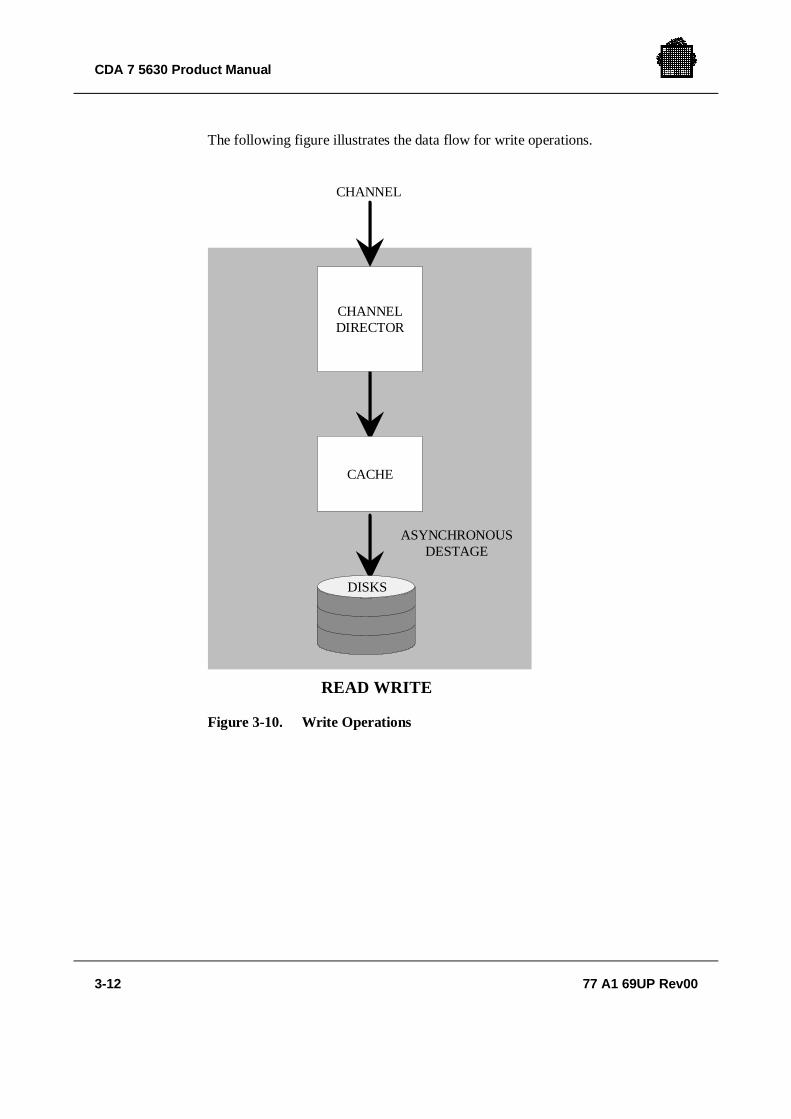
For write operations, the channel director sends a device end and channel end (or aSCSI good ending status) to the channel as soon as the data is in cache and verifiedas error-free so the host system can continue processing without having to wait forCDA 7 to write the data to disk. The disk director asynchronously "destages" thedata to disk.
There are two types of write operations:
• Fast Write
• Delayed Fast Write
CDA 7 5630 Product Manual
3-12 77 A1 69UP Rev00
The following figure illustrates the data flow for write operations.
CHANNEL
READ WRITE
ASYNCHRONOUSDESTAGE
CHANNELDIRECTOR
CACHE
DISKS
Figure 3-10. Write Operations

CDA 7 Input/Output Operations
77 A1 69UP Rev00 3-13
3.2.3.1 Fast Write
In a fast write operation, the channel director stores the data in cache and sends achannel end and device end (or a SCSI "good ending" status) to the host computer.The disk director then asynchronously "destages" the data from cache to the diskdevice.
CONNECT TIME
OVERHEAD
TOTAL SERVICE TIME
Figure 3-11. Fast Write
Since CDA 7 writes the data directly to cache and not to disk, there are nomechanical delays due to seek, latency, and RPS miss.

CDA 7 5630 Product Manual
3-14 77 A1 69UP Rev00
3.2.3.2 Delayed Fast Write
In a delayed fast write operation, CDA 7 cannot store the data in cache until spacein cache becomes available. A delayed fast write condition can only happen if thecache allocated for writes is currently full with data yet to be "destaged" to the diskdevices. The default cache write ceiling is 80% of the cache.
CONNECT TIME
OVERHEAD
TOTAL SERVICE TIME
DISCONNECT TIME
DELAY NORMALFAST WRITE
Figure 3-12. Delayed Fast Write
Should this situation occur, CDA 7 disconnects the channel directors from thechannels and waits for the disk directors to "destage" the Fast Write data in cacheto disk. When space in cache is available, CDA 7 reconnects the channel directorsto their channels and completes the write operation. CDA 7 continues to processread operations during delayed fast writes.

77 A1 69UP Rev00 4-1
4. Performance Features
CDA 7 offers improved performance over conventional Storage Control Units anddisk device designs. The CDA 7 features described below allow high cache hitratios and less processing overhead, reducing response time and improvingthroughput.
4.1 Cache
A cache size of up to 8,192 MB and intelligent caching algorithms greatly improvehit ratios and overall subsystem response time. CDA 7 caches all read and writeoperations making them transparent to the host operating system.
4.2 Multiple Channel Directors
CDA 7 contains multiple channel directors, Ultra SCSI or fibre channel type, eachsupplying an independent path to cache or disk from the host system. TheCDA 7 has two or four channel directors.
Each Ultra SCSI director supports up to four SCSI channels.
Each fibre channel director supports two Fibre channel ports.
4.3 Parallel Processing
Each channel director and disk director has two resident microprocessors, and eachdisk device has one resident microprocessor. These microprocessors make use ofadvances in parallel processing to reduce processing time and improve throughput.

CDA 7 5630 Product Manual
4-2 77 A1 69UP Rev00
4.4 Fast Write Capabilities
CDA 7 caches write operations, eliminating the need to write data to the diskimmediately. This results in faster response times and improved overall subsystemperformance. The write ceiling is 80% of the usable cache. Channel directors anddisk directors dynamically allocate cache space between reads and writesdepending on I/O activity.
4.5 Dynamic Mirror Service Policy
The CDA 7 Dynamic Mirror Service Policy (DMSP) is an enhancement to theadaptive algorithms in the CDA 7 architecture that improves the performance ofread operations in mirrored environments. The improved system performance is aresult of CDA 7 balancing the load between physical disk drives and disk directors,and minimizing actuator movement.
To achieve this improved performance, CDA 7 measures and tracks I/O activitiesof logical volumes, physical volumes and disk directors. Then, based on thesemeasurements, CDA 7 directs read operations for mirrored data to the appropriatemirror that results in the best overall performance of the CDA 7 . As the accesspatterns and workloads change, the dynamic algorithm analyzes the new workloadsand adjusts the service policies as needed.
4.6 RPS Miss Elimination
In CDA 7, each disk device has a dedicated microprocessor and segmented databuffer that can temporarily store data until the disk director is ready to read or writedata. This eliminates rotational positional sensing (RPS) misses that occur inconventional disk device when the heads are positioned over the desired sector, butthe channel path is not ready for read or write operations. The segmented databuffer of the disk device allows multiple operations to occur to the head/diskassemblies.
4.7 Channel Speed
CDA 7 Ultra SCSI channels transfer data at speeds up to 40 MB/sec. The datatransfer rate is host dependent. CDA 7 supports cable lengths of up to 82 feet (25m) to attach to most host systems.

77 A1 69UP Rev00 5-1
5. Managing Critical Data
This chapter discusses the CDA 7 features and options that affect data availabilityand reliability.
• CDA 7 Data Management Overview
• Reliability and Availability Features
• Data Integrity Protection
• Data Protection Guidelines
• Mirroring
5.1 CDA 7 Data Management Overview
CDA 7 has many features and options to ensure a high degree of system and dataavailability.
Many of these features and options are built into the CDA 7 design. Otheravailability options may be purchased separately and implemented in the CDA 7operation.
5.1.1 CDA 7 Reliability and Availability Features
The CDA 7 design offers the following reliability and availability features:
• High reliability components• Redundant power subsystem• System battery backup• Dual-Initiator feature• Non-disruptive maintenance and microcode upgrades

CDA 7 5630 Product Manual
5-2 77 A1 69UP Rev00
These basic CDA 7 features provide protection against loss of system and dataavailability due to a power loss or failed component. A redundant design allowsCDA 7 to remain online and operational during component repair. For example, ifa power supply fails, the remaining power supplies share the load until the failedcomponent is replaced. The system battery backup prevents any loss of data due toa power failure.
The Dual-Initiator feature offers data availability protection against a CDA 7 diskmanagement component failure. With dual-initiator, each member of a diskdirector pair shadows the functions of the other disk director. That is, each diskdirector can service any or all of the devices attached to the disk director withwhich it is paired. This feature does not, however, provide data availability in theevent of a disk device failure. Should CDA 7 detect a disk management hardwarefailure, CDA 7 automatically reads from or writes to the disk devices it was unableto communicate with via the other disk director in the pair.
5.1.2 CDA 7 Data Integrity Protection Features
The CDA 7 is designed with these data integrity features:
• Error checking, correction, and data integrity protection
• Disk error correction and error verification
• Cache error correction and error verification
• Periodic system checks
Error verification prevents temporary errors from accumulating and resulting inpermanent data loss. CDA 7 also looks at the error verification frequency as asignal of a potentially failing component.
The periodic system check tests all components as well as microcode integrity.CDA 7 reports errors and environmental conditions to the host system as well asthe Bull Competence Center.

Managing Critical Data
77 A1 69UP Rev00 5-3
5.1.3 Data Protection Options
Although the CDA 7 has standard features that provide a higher level of dataavailability than conventional disk, the options listed below ensure an even greaterlevel of data recoverability and availability.
You can choose from the following CDA 7 data protection options to match yourcritical data requirements:
• RAID-1 Mirroring
• CDA 7 Remote Data Facility (SRDF)
5.1.3.1 RAID-1 Option (Mission Critical/ Business Critical)
Mirroring provides the highest performance, availability, and functionality for allmission critical and business critical applications. With the Mirroring option,CDA 7 maintains two identical copies of a logical volume on separate disk devices.Should CDA 7 be unable to read data from one volume of a mirrored pair, itimmediately retrieves the data from the other logical volume.
5.1.3.2 CDA 7 Remote Data Facility (SRDF)
The CDA 7 SRDF option is a mechanism that maintains a mirror image of data at alogical volume level in two CDA 7 subsystems that can be located in physicallyseparate sites.
Within the Bull DPS 7000/GCOS 7 environment, the SRDF for GCOS 7 solution isaimed at providing a back-up solution in the situation where a production site is outof work due to a major disaster event. Refer to § SRDF for GCOS 7.

CDA 7 5630 Product Manual
5-4 77 A1 69UP Rev00
5.2 Reliability and Availability Features
CDA 7 has several features that allow it to maintain data integrity and maximizesystem availability. This section discusses several features in detail.
5.2.1 Reliable Components
CDA 7 uses components that have a mean time between failure (MTBF) of severalhundred thousand to millions of hours for a minimal component failure rate. Aredundant design allows CDA 7 to remain online and operational duringcomponent repair.
A periodic system check tests all components as well as microcode integrity.CDA 7 reports errors and environmental conditions to the host system as well asthe Bull Competence Center.
5.2.2 Redundant Power Subsystem
The CDA 7 has a modular power subsystem featuring a redundant architecture thatfacilitates field replacement of any of its components without any interruption inprocessing.
The CDA 7 power subsystem connects to two dedicated or isolated AC powerlines. If AC power fails on one AC line, the power subsystem automaticallyswitches to the other AC line.
The two power supplies operate in a redundant parallel configuration. If a powersupply module fails, the remaining power supply continue to share the load. CDA 7senses the fault and reports it as an environmental error (error code 0472).
5.2.3 System Battery Backup
The entire CDA 7 system is made nonvolatile via an onboard battery backupsystem. The battery backup system provides the means for destaging any fast writedata that might be in cache if AC power is lost on both AC power lines to the unit.In addition to providing nonvolatility to the CDA 7 system, the batteries are fullycapable of powering not only all electronic components, but also all HDAs duringthis time. This eliminates emergency power off situations, meaning that the disksare always powered down in an orderly manner, which extends their useful lifeconsiderably.

Managing Critical Data
77 A1 69UP Rev00 5-5
The backup battery subsystem allows CDA 7 to remain online to the host systemfor three minutes in the event of an AC power loss. This three minute windowallows CDA 7 to support frequent power outages because the battery is able tofully recharge during Initial Microcode Load (IML) time. CDA 7 continuallyrecharges the battery subsystem whenever it is under AC power.
The battery backup also prevents disk device failures due to the sharp power dropsthat occur during unexpected power interrupts. If power is restored before thebattery timer expires, CDA 7 becomes available again without IML.
5.2.3.1 CDA 7 Power Failure on GCOS 7 Channels Connected to GCOS 7
When a power failure occurs, power switches immediately to the backup batteryand CDA 7 continues to operate normally. When the battery timer window elapses,CDA 7 presents a busy status to prevent the host system from writing or readingany data at the unit. CDA 7 destages any Fast Write data still in cache to disk,spins down the disk devices and retracts the heads, and powers down, turning offthe battery at that time. CDA 7 will not respond to SCSI selections after it powersdown.
5.2.4 Dual-Initiator Feature
CDA 7 has a dual-initiator feature that ensures continuous availability of data inthe unlikely event of a CDA 7 disk management hardware failure. It does notprovide data availability in the event of a disk device failure. This feature worksby having two disk directors “shadow” the function of the other. That is, thisfeature gives each disk director the capability of servicing any or all of the diskdevices of the disk director with which it is paired when one disk director iscompletely servicing its own and the shadowed devices.
With dual-initiator, the disk directors work in pairs. See the figures on thefollowing pages. Under normal conditions, each disk director services its diskdevices. If the sophisticated fencing mechanisms of CDA 7 detect a diskmanagement hardware failure, CDA 7 notifies the host and the Bull CompetenceCenter of the failure, and reads from or writes to the disk devices that its diskdirector pair was unable to communicate with without interruption. When thesource of the failure is corrected, CDA 7 returns the I/O servicing of the two diskdirectors to their normal state.

CDA 7 5630 Product Manual
5-6 77 A1 69UP Rev00
This sophisticated fencing mechanism determines a disk management hardwarefailure at two levels:
Level 1: a director discovers through use of its onlineself-testing that one of its SCSI paths is failing. Thedirector signals CDA 7 of this condition and thedirector it is paired with automatically takes control ofthe failing path.
Level 2: CDA 7 determines a director has failed and fences itout. The director’s associated pair automatically takescontrol of all its devices.

Managing Critical Data
77 A1 69UP Rev00 5-7
DISK DIRECTOR 2
PROCESSORA
PROCESSORB
PC PD SC SD PC PD SC SD
TO/FROMMEMORY
DISKS
DISK DIRECTOR 1
PROCESSORA
PROCESSORB
PC PD SC SD PC PD SC SD
DISKS
DISKS
DISKS
DISKS
DISKS
DISKS
DISKS
PC = PRIMARY C BUSPD = PRIMARY D BUSSC = SECONDARY C BUSSD = SECONDARY D BUS
= PRIMARY SCSI PATHS TO DISKS= SECONDARY SCSI PATHS TO DISKS
Figure 5-1. CDA 7 Dual-Initiator

CDA 7 5630 Product Manual
5-8 77 A1 69UP Rev00
In the following examples, disk director 1 and disk director 2 are paired. EachCDA 7 disk director services 16 disk devices.
EXAMPLE 1:
Disk director 1 fails. Disk director 2 automatically performs any I/O operationswith all of the devices normally serviced by disk director 1 as well as all its owndisk devices with no interruption in processing.
❑
EXAMPLE 2:
On disk director 1, processor A, primary SCSI bus C fails. On disk director 2,processor B, primary SCSI bus D fails. The devices of these failing buses areserviced as follows:
• The devices of failing bus C, are serviced by disk director 2, processor A,secondary SCSI bus C.
• The devices of failing bus D are serviced by disk director 1, processor B,secondary SCSI bus D.
The functioning primary buses on each of the disk directors continue to servicetheir respective devices.
❑
EXAMPLE 3:
On disk director 2, processor A, primary SCSI buses C and D fail. The devices ofthese failing buses are serviced as follows:
• The devices of failing bus C are serviced by disk director 1, processor A,secondary SCSI bus C.
• The devices of failing bus D are serviced by disk director 1, processor A,secondary SCSI bus D.
The functioning primary buses of disk director 2 continue to service theirrespective devices.

Managing Critical Data
77 A1 69UP Rev00 5-9
In summary, dual-initiator provides the following advantages:
• Ensures continuous data availability if a CDA 7 disk management componentfails
• Provides continuous operation by switching data pathing to the alternate diskdirector without interruption when a communications failure occurs with one ormore disk devices
• Re-establishes normal data pathing after repair of the defective component
Dual-initiator provides an additional level of data availability in mirroredconfigurations. If CDA 7 is unable to read from or write to one of the devices in amirrored pair, CDA 7 automatically uses the other disk device in the pair withoutinterruption. If CDA 7 fails to communicate with that device also, CDA 7 thenattempts to access the volume through the alternate path provided by the dual-initiator function.
❑
5.2.5 Non-disruptive Component Replacement
CDA 7, with its redundant architecture, supports non-disruptive replacement ofmany of its components. This includes online replacement of the directors(channel directors and disk directors), memory cards, disk devices, adapters(dual-initiator, serial), power supplies, communications cards, and cooling fans.
This non-disruptive replacement capability allows the Bull Customer Engineer toinstall a new component, initialize it if necessary, and bring it online without:
• Disrupting access to unaffected volumes• Powering down the CDA 7 unit• Stopping the operating system• Taking unaffected channel paths offline• Taking devices offline (other than the affected device)
This replacement must be done under controlled conditions, please contact yourBull Competence Center. For a demonstration of non-disruptive componentreplacement, contact your Bull Customer Service representative.
NOTE:When replacing a Director, all activity on the director must be stopped beforeattempting this operation.

CDA 7 5630 Product Manual
5-10 77 A1 69UP Rev00
5.2.6 Microcode Upgrades and Loads
Microcode upgrades, performed by the Product Support Engineers (PSE) at theBull Competence Center, allow you to take advantage of enhancements toperformance algorithms, error recovery and reporting techniques, diagnostics, andmicrocode fixes.
It is possible to upgrade the microcode from one level to an adjacent level.Problems can happen when upgrading to a much higher microcode level.
5.2.6.1 Non-disruptive Microcode Upgrades and Loads
Non-disruptive microcode upgrades from one version to the next and interimmicrocode updates (loads) are available for CDA 7 systems. Symmetrix takesadvantage of its multiprocessing and redundant architecture to allow for hotloadability of similar microcode platforms. Release levels can be non-disruptivelyloaded without interruption to user access.
During a non-disruptive microcode upgrade, the Product Support Engineerdownloads the new microcode to the service processor. The new microcode loadsinto the EEPROM areas within the channel and disk directors and remains idleuntil requested for hot load in control storage. The CDA 7 system does not requiremanual intervention on the customer’s part to perform this function. All channeland disk directors remain in an online state to the host processor, thus maintainingapplication access. CDA 7 will load executable code at selected "windows ofopportunity" within each director hardware resource until all directors have beenloaded.
Once the executable code is loaded, internal processing is synchronized and thenew code becomes operational. This capability can be utilized to upgrade or toback down from a release level or interim update.
NOTE:During a non-disruptive microcode load within a code family, the fullmicrocode is loaded, which consists of the same base code plus additionalpatches.

Managing Critical Data
77 A1 69UP Rev00 5-11
5.2.6.2 Dynamic Reconfigurations
CDA 7 supports dynamic reconfiguration activity without disruption to onlineapplications, such as:
• Establish/de-establish mirrored pairs.• Modify channel assignments.
5.2.6.3 Online SCSI-to-Fibre Channel Migration
Beginning with CDA 7 microcode revision 5265, CDA 7 systems with SCSIchannel directors can be upgraded to Fibre Channel directors without taking non-SCSI channels offline and without requiring a backup and restore of data. Thiscapability allows customers with SCSI channels to take advantage of theconnectivity and distance features offered with Fibre Channel directors. BullCustomer Engineers use a new utility to perform the migration.
NOTE:For more information on Fibre Channel migration, consult your Bull salesrepresentative.

CDA 7 5630 Product Manual
5-12 77 A1 69UP Rev00
5.3 Data Integrity Protection
CDA 7 preserves data integrity by performing extensive error checking andcorrection on all data and addresses it passes internally.
5.3.1 Error Checking, Correction, and Data Integrity Protection
In conventional disk, the subsystem adds error checking and correction bytes toeach data record field, as shown in the following figure. It uses these errorchecking and correction bytes to check the data and correct it if possible. If itdetects an uncorrectable error, the disk subsystem informs the host that it hasencountered bad data to avoid affecting data integrity.
DATA RECORDECC
BYTES
Figure 5-2. Data Record Format for Conventional Disk
CDA 7, like conventional disk, performs this level of error checking and correctionwhen it passes data and addresses. CDA 7, however, goes further to ensure that theinformation passed belongs to the record specified. It does this by includingadditional bytes with the data field of each record. These bytes contain the recordID and a double LRC (Longitude Redundancy Code) check byte as shown in thefollowing figure. CDA 7 uses these bytes to check that the data is from thespecified record and alarms the host if it is not. This second level of protectionfurther ensures data integrity by preventing incorrect data from being transferred.
DATA RECORDEMBEDDED
IDECC
BYTESLRC
BYTES
Figure 5-3. CDA 7 Data Record Format
CDA 7 has three levels of error detection. Should an error be undetected at onelevel, it will be detected at one of the other levels.
CDA 7 uses the following error correction and detection methods:
• Parity• Error Checking and Correction (ECC)• Longitude Redundancy Code (LRC)

Managing Critical Data
77 A1 69UP Rev00 5-13
5.3.1.1 Parity
All data and control paths have parity generating and checking circuitry that verifyhardware integrity at the byte level.
5.3.1.2 ECC
The directors detect and correct single-bit and double-bit errors and reportuncorrectable 3-bit or more errors in cache.
5.3.1.3 LRC
The LRC calculation further assures data integrity. The check bytes are the XOR(exclusive OR) of the accumulated bytes. Each record in memory also includes itsLRC byte, its physical memory address, and block number.
5.3.2 Disk Error Correction and Error Verification
The disk directors use idle time to read data and check the polynomial correctionbits for validity. If a disk read error occurs, the disk director reads all data on thattrack to CDA 7 cache memory. The disk director writes several worst case patternsto that track searching for media errors. When the test completes, the disk directorrewrites the data from cache to the disk device, verifying the write operation. Thedisk microprocessor maps around any bad block (or blocks) detected during theworst case write operation, thus skipping defects in the media. If necessary, thedisk microprocessor can reallocate up to 32 blocks of data on that track. To furthersafeguard the data, each disk device has several spare cylinders available. If thenumber of bad blocks per track exceeds 32 blocks, the disk director rewrites thedata to an available spare cylinder. This entire process is called “errorverification.”
The disk director increments a soft error counter with each bad block detected.When the internal soft error threshold is reached, the CDA 7 service processorautomatically dials the Bull Competence Center and notifies the host system oferrors via sense data. This feature maximizes data availability by diagnosingmarginal media errors before data becomes unreadable.

CDA 7 5630 Product Manual
5-14 77 A1 69UP Rev00
5.3.3 Cache Error Correction and Error Verification
The disk directors use idle time to periodically read cache, correct single-bit errors(one hard and one soft), and write the corrected data back to cache. This process iscalled “error verification.” When the directors detect an uncorrectable error incache, CDA 7 reads the data from disk and takes the defective cache memory blockoffline until an Bull Customer Engineer can repair it. Error verification maximizesdata availability by significantly reducing the probability of encountering anuncorrectable error by preventing bit errors from accumulating in cache.
5.4 Data Protection Guidelines
The CDA 7 data protection options ensure a higher level of data protection,recoverability, and availability than the standard CDA 7 availability and reliabilityfeatures. The following options can be purchased separately and implemented intothe CDA 7 operation:
• Mirroring
• CDA 7 Remote Data Facility (SRDF)
The following table describes the CDA 7 data protection options. You can chooseone or more of these options to match your critical data protection requirements.
Table 5-1. Data Protection Options
Data Protection Option DescriptionMirroring (RAID-1) Provides the highest level of performance and
availability for all mission critical and businesscritical applications by maintaining a duplicatecopy of a volume on two disk devices.
For more information, refer to Mirroring.CDA 7 Remote DataFacility (SRDF)
Provides a disaster recovery solution bymaintaining a mirror image of data in twoCDA 7 systems which can be in physicallyseparate locations.For more information, refer to SRDF.

Managing Critical Data
77 A1 69UP Rev00 5-15
5.5 Mirroring
Mirroring provides the highest level of performance and availability for all missioncritical and business critical applications. Mirroring maintains a duplicate copy ofa logical volume on two physical disk devices. CDA 7 maintains these copiesinternally by writing all modified data to both devices. The mirroring operation istransparent to the host.
The mirroring feature designates two logical volumes residing on different physicaldevices as a mirrored pair, one volume being mirror-1 and the other volume beingmirror-2. The host views the mirror-1 and mirror-2 volumes as the same logicalvolume because each has the same unit address.
5.5.1 Write Operations with Mirroring
CDA 7 handles a write operation to a mirrored logical volume as a normal writeoperation. The channel director presents channel end and device end (or a goodending status) to the channel after data is written to and verified in cache. The diskdirectors destage the data to each logical volume in the mirrored pair maintainingthe identical copies of data.
5.5.2 Read Operations with Mirroring
During read operations, if the data is not available in cache, CDA 7 reads the datafrom the disk pointed to by its performance algorithm for best system performance.This performance algorithm tracks path busy information as well as actuatorlocation and what sector is currently under the disk head in each device. If a datacheck occurs on the device being read, CDA 7 automatically reads the data fromthe other device.
• Interleave Service Policy shares the read operations of the mirrored pair byreading tracks from both disk devices in an alternating method, a number oftracks from M1, and a number of tracks from M2. Interleave is designed toachieve maximum throughput.
• Split Service Policy differs from Interleave because read operations areassigned to either the M1 or the M2, but not to both.
• Dynamic Mirror Service Policy (DMSP) utilizes both Interleave and Split formaximum throughput and minimal head movement. DMSP adjusts each logicalvolume dynamically based on access patterns detected.
CDA 7 5630 Product Manual
5-16 77 A1 69UP Rev00
5.5.3 Error Recovery with Mirroring
Should one volume in the mirrored pair fail, CDA 7 automatically uses the othervolume without interruption. CDA 7 notifies the Bull Competence Center of thiscondition. When the defective device containing the volume is replaced, CDA 7re-establishes the mirrored pair and automatically copies data to the new disk.During the copy operation, CDA 7 gives priority to host I/O requests over copyingto minimize the effect on performance. All new writes take place to both devices.The time it takes to resynchronize the mirrored pair depends on the I/O activity tothe volume, the disk device, and the disk capacity.
5.5.4 Mirroring Advantages
In summary, mirroring offers the following advantages:
• Improved performance over traditional RAID 1 by supporting 100 percent fastwrite, and two simultaneous internal data transfer paths.
• Protection of mission-critical data from any single point of failure.
• Continuous business operation by switching to the alternate disk device of amirrored pair without interruption to data availability should loss of access occurto one of the disk devices in a mirrored pair.
• Assurance that the second copy of data is identical to the first copy.
• Automatic resynchronization of the mirrored pair after repair of the defectivevolume.
5.6 SRDF for GCOS 7
The SRDF for GCOS 7 Solution is aimed at providing a complete businesscontinuance capability during the unlikely event of a data center disaster.
SRDF for GCOS 7 is based on CDA 7 SRDF mechanism allowing for a physicalremote copy of disk volumes and operating
• in campus mode with ESCON-compliant fiber optics link or high speed datalines,
• in synchronous mode for a full logical synchronisation of mirrored volumes,
• with the two involved CDA 7’s configured in RAID-1.

Managing Critical Data
77 A1 69UP Rev00 5-17
In case of disaster occuring at the Production Site, the back-up procedures entitlethe Back-up Site to take over the application workload and to resume theproduction tasks thanks to the remote copy of user’s databases and system data.
SRDF for GCOS 7
• is a very powerful solution with simple back-up procedures which aretransparent for user’s applications,
• avoids the need of time-consuming restore operations,
• is capable to quickly resume the business operations with minimal disruption.
SRDF for GCOS 7 is commercialized in a Project Mode. Contact your Bull SalesEngineer.
CDA 7 5630 Raid-1 CDA 7 5630 Raid-1
Back-upSite
BATCHIOF
Local Remote
ProductionSite
Bull DPS 7000
ESCON
SRDFRLD
RLD
Bull DPS 7000
RLD = Remote Link Director
DEVELOPMENT,TEST…
TDS

CDA 7 5630 Product Manual
5-18 77 A1 69UP Rev00
❑ ❑
77 A1 69UP Rev00 A-1
A. Power Sequences
This Appendix provides step-by-step instructions for powering the CDA 7 on andoff. The unit is powered on and off via the power switches on the rear door of theunit.
• Powering Up the CDA 7 • Routinely Powering Down CDA• Emergency Shutdown• Powering Up After an Emergency Shutdown
A.1 Powering Up the CDA 7
DANGER:If the CDA 7 is in need of repair, only qualified personnel familiar withsafety procedures for electrical equipment and the CDA 7 should accesscomponents inside the unit.
Perform these steps to power on the CDA 7 after it has been powered off by the ACpower switch.
1. Make sure all operator panel switches (channel director and disk director) arein the disable position.
2. Lift the EPO switch on the rear door to the up (|) position.
3. Lift the AC power switch on the rear door to the up (|) position. The CDA 7begins its IML procedure. This procedure takes several minutes to perform.
NOTE:The power controls are inoperative unless the Emergency Power Off (EPO)switch on the rear door is in its enabled (up, | position). The EPO switch whenturned off (down, O position) disables all power to CDA 7 including the backupbattery systems.
CDA 7 Product Manual
A-2 77 A1 69UP Rev00
4. When the IML procedure completes (all directors show "0F" in their LEDdisplays on their front panels), place the operator panel switches (channeldirector and disk director) in their enable position.
When "0F" clears from all director LED displays, the CDA 7 is then availableto the host system(s).
A.2 Routinely Powering Down CDA
Perform these steps to power off the CDA 7 using the AC power switch.
1. Stop all processes to the CDA 7.
2. Watch the operator panel and wait for all "Active" LEDs to stop flashing.
NOTE:The displays stop flashing when the CDA 7 has written all cache data to disk.
3. Press the AC power switch on the rear door to the down (O) position.
NOTE:The battery backup system automatically turns on when the CDA 7 detects lossof AC power. The battery will keep the CDA 7 powered for 3 minutes followingwhich CDA 7 turns off.
A.3 Emergency Powering Down
If it becomes necessary to power off the CDA 7 immediately:
• Press the red EPO switch on the rear door to the down (O) position.
NOTE:CDA 7 immediately switches to backup battery power and destages any pendingwrites in cache to disk. This destage operation takes approximately 20 secondsfollowing which CDA 7 powers down.
IMPORTANT:When there is an emergency power cut, data in the cache might not besaved on the physical disks.
13
3

Power Sequences
77 A1 69UP Rev00 A-3
A.4 Powering Up After an Emergency Shutdown
CAUTION:This unit contains no user-serviceable parts, so it should not be opened forany reason by untrained personnel. If the CDA 7 is in need of repair, onlyqualified personnel familiar with safety procedures for electrical equipmentand the CDA 7 should access components inside the unit.
When the CDA 7 is powered down via the red EPO switch, a breaker switch on thepower subsystem trips.
Perform these steps to power on the CDA 7 after it has been powered off by the redEPO switch.
CAUTION:Always contact the Bull Customer Support Center prior to powering up theCDA 7 after an emergency shutdown.
1. Make sure all operator panel switches (channel director and disk director) arein the disable position.
2. Lift the EPO switch on the rear door to the up (|) position.
3. Lift the AC power switch on the rear door to the up (|) position.
NOTE:The CDA 7 begins its IML procedure. This procedure takes several minutes toperform.
4. When the IML procedure completes, all directors show "0F" in their LEDdisplays.
CAUTION:Before you enable channel and disk directors from the CDA 7 operatorpanel, contact an EMC Product Support Engineer from the EMCCustomer Support Center. Explain that an emergency shutdown wasperformed and that you need them to check the condition of the CDA 7before you enable the channel and disk directors. When the CDA 7 checksout correctly, proceed to the next step.
5. Place the operator panel switches (channel director and disk director) in theirenable position.
When "0F" clears from all director LED displays, the CDA 7 is then availableto the host system(s).
CDA 7 Product Manual
A-4 77 A1 69UP Rev00
❑

77 A1 69UP Rev00 B-1
B. ESP Installation Requirements
This Appendix covers the tasks you need to perform when planning or verifyingthe physical configuration of CDA 7 in your system or creating I/O addressingschemes.
B.1 CDA 7 Hardware Checklist
Make sure you discuss with and obtain the following site profile information withthe Customer Engineer and/or Systems Engineer. This information is necessary foreach CDA 7 subsystem you are installing (following table).
Table B-1. CDA 7 Host Checklist
CDA 7 ModelTotal number of physical drives to be configured on theCDA 7Physical drive type (size)Total amount of CDA 7 cacheNumber of SCSI channel or Fibre channel directorsUltra channel director model usedNumber of Ultra channels used per directorFibre channel director model usedNumber of fibre port used per director

CDA 7 5630 Product Manual
B-2 77 A1 69UP Rev00
B.2 Open Checklists for ESP Connection
Make sure you discuss with and provide the following host information to theCustomer Engineer and/or Systems Engineer. This information is necessary foreach host you are attaching to the CDA 7 subsystem. Make a copy of this form foreach host you will attach to CDA 7. When you are done you should have achecklist for each host.
Table B-2. Open System Server Host Checklist (1/2)
Host Configuration Requirements Host 1 Host 2Host (CPU) vendor and model numberHost controller type and model numberMemory capacity of hostO/S revision level of hostI/O rate per second expected per hostSCSI adapter used on host, type and modelnumberIs this a clustered environment? Which one?Will devices be shared? Which ones?Total number of SCSI channels per host, towhich SA ports will they attach?Total number of Fibre channels per host, towhich FA ports will they attach ?Specify if any narrow channels usedNumber of logical devices needed per SCSI bus
Size of volumes required to be visible to host1
Total customer usable data storage requiredWill host-level mirroring be used, whichvolumes?Will CDA 7 Dynamic Sparing (specify numberof spares) be used, which volumes?Will CDA 7 RAID-1 be used, which volumes?Will SRDF be used, which volumes?
Data storage utilization per host2
Average transfer size of dataUsing raw devices or filesystems?Size of filesystem

ESP Installation Requirements
77 A1 69UP Rev00 B-3
Table B-2. Open System Server Host Checklist (2/2)
Host Configuration Requirements Host 1 Host 2Will data stripping be used?What type of data stripping package?Partitioning?Partition sizes?
LVM used3
What major applications are to be run?Database used:Oracle®/Sysbase®/Informix®/other?Size of databaseDatabase release versionSupply typical high level database schema andqueriesAny patches or modifications related toIO/SCSI?Additional comments
NOTES:1. This is the volume size needed for each volume visible on the SCSI bus.
2. Percentage of available CDA data capacity used by that host.
3. Special attention is required when using a Logical Volume Manager(LVM) and/or data stripping when using hyper-volumes.

CDA 7 5630 Product Manual
B-4 77 A1 69UP Rev00
B.3 SCSI Cable Worksheet
The physical connection to a Ultra channel interface occurs at the connectors onthe SCSI adapters located at the rear of the CDA 7 unit.
When connecting to hosts with differential Ultra or differential narrow SCSIinterfaces, use differential P-cables that are designed for wide SCSI applications(see labeling on cable).
NOTE:For a list of the Ultra SCSI cables available from Bull, refer to the manualCDA 7 Site Preparation. You can use the following table as a cable worksheetform.
Table B-3. Cable Worksheet
SCSIDirector
SCSIDirector
Port
CableLength
Required
Cable ModelNumber or Part
Number
Host ID ModelNumber
1A a1A b1B a1B b2A a2A b2B a2B b3A a3A b3B a3B b4A a4A b4B a4B b

ESP Installation Requirements
77 A1 69UP Rev00 B-5
B.4 ULTRA SCSI Channel Adapters
Several Fast-Wide / Ultra SCSI adapters are available in CDA 7, depending on thehost channel connection requirements, such as terminated and non-terminatedchannels, and Y-cable cluster configurations.
NOTE:Contact your Bull Sales Representative to obtain SCSI adapter part numbers.For cluster configurations, refer to the Symmetrix High Availability EnvironmentProduct Guide.
B.5 SCSI Cable Precautions
When connecting CDA 7 Ultra SCSI channels to host channels it is important toknow CDA 7 Ultra SCSI hardware components and their channel designations.
Each Ultra SCSI director occupies one slot on the CDA 7 backplane. Each directorinterfaces to the host channels via a SCSI adapter connected to the opposite side ofthe backplane.
The Ultra SCSI director contains two advanced microprocessors. Eachmicroprocessor has two wide-differential SCSI channels. The following figureillustrates this interface and the channel designations.
NOTE:When connecting the CDA 7 SCSI cables to the host channels, notice that the"A" processor channels are on the bottom and the "B" processor channels are onthe top.

CDA 7 5630 Product Manual
B-6 77 A1 69UP Rev00
SDAOperator PanelDesignations
X-BUS
PhysicalChannel
Designations
C
D
A
B
SA-1, SIDE B, PORT A
SA-1, SIDE B, PORT B
SA-1, SIDE A, PORT A
SA-1, SIDE A, PORT B
A
A
B
B
ADAPTER DIRECTOR
B
A
B-SIDE
A-SIDE
Four-Port Dual-Processor, UltraSCSI Director
HOSTCHANNELS
MID
PL
AN
EFigure B-1. Ultra SCSI Director Channel Designations
Additional Precautions
Observe the following precautions when connecting SCSI cables to the CDA 7SCSI channel interface connectors:
• Use the shortest cabling possible between the CDA 7 unit and the host.
• Always check for bent pins on the SCSI cables before connecting them. TheSCSI cable pins bend very easily.
• Always attach SCSI cables to their connectors straight on to minimize thechance of bending pins.
• The pin shroud on the SCSI cable ends deforms easily. Take care not to dropcable ends or bang them against objects.
• When attaching the SCSI cable to the connector on the SCSI adapter in the CDAunit, remember to fasten the screws on the connector to ensure a secureconnection.
• When connecting to hosts with differential Fast-Wide SCSI interfaces, do notallow the cable length to exceed 82 feet (25 m).
• When connecting to hosts with Ultra SCSI interfaces, do not allow the cablelength to exceed 62 feet (19 m).
• Fibre Channel interfaces extend connectivity up to a maximum of 1600 feet (500meters).
77 A1 69UP Rev00 G-1
Glossary
This glossary contains terms related to disk storage subsystems. Many of theseterms are used in this manual.
A
ActuatorA set of access arms and their attached read/write heads, which move as an independent componentwithin a head and disk assembly (HDA).
AdapterCard that provides the physical interface between the director and disk devices (dual-initiatoradapter), director and parallel channels (Bus & Tag adapter), director, serial channels (serialadapter), and SCSI host channels (SCSI adapter).
ADTAutomatic Diagnostic Test.
Alternate TrackA track designated to contain data in place of a defective primary track. See also Primary Track.
ANSIAmerican National Standards Institute. A standards-setting, non-government organization whichdevelops and publishes standards for voluntary use in the USA.
Asynchronous TransmissionA handshaking protocol that requires each byte be requested and acknowledged before thetransmission of the next byte begins.

CDA 7 5630 Product Manual
G-2 77 A1 69UP Rev00
B
BackplaneCard that accommodates the director, cache, and adapter cards.
BitThe smallest unit of computer memory. A bit can hold a value of 0 or 1.
ByteTerm that indicates an 8-bit hexadecimal construction.
C
CacheRandom access electronic storage used to retain frequently used data for faster access by thechannel.
Cache SlotUnit of cache equivalent to one track.
Channel DirectorThe component in the Symmetrix subsystem that interfaces between the host channels and datastorage. It transfers data between the channel and cache.
Command Descriptor Block (CDB)The structure used to communicate commands from an initiator to a target. This structure may be 6bytes, 10 bytes, or 12 bytes in size.
D
Data AvailabilityAccess to any and all user data by the application.
Delayed Fast WriteThere is no room in cache for the data presented by the write operation. Therefore, the write isdelayed until there is room in cache.
DestageThe asynchronous write of new or updated data from cache to disk device. See also the term"Stage".
DeviceA uniquely addressable part of the Symmetrix subsystem that consists of a set of access arms, theassociated disk surfaces, and the electronic circuitry required to locate, read, and write data. Seealso Volume.
Device NumberThe value that logically identifies a disk device in a string.

Glossary
77 A1 69UP Rev00 G-3
DiagnosticsSystem level tests or firmware designed to inspect, detect, and correct failing components. Thesetests are comprehensive and self-invoking.
Differential InterfaceAn electrical signal configuration that uses a pair of lines for transfer. This configuration (ascompared to a single-ended interface) has a higher tolerance for common-mode noise and littlecrosstalk when used with twisted pair cables. It supports cables lengths to 25 meters (82 feet). Seealso Single-ended Interface.
DirectorsThe components in the Symmetrix subsystem that allows Symmetrix to transfer data between thehost channels and disk devices. See also Channel Director and Disk Director.
Disk DirectorThe component in the Symmetrix subsystem that interfaces between cache and the disk devices.
DMADirect Memory Access.
Dual-InitiatorA Symmetrix feature that automatically creates a backup data path to the disk devices serviceddirectly by a disk director, if that disk director or the disk management hardware for those devicesfails.
Dynamic Path Reconnect (DPR)A function that allows disconnected I/O operations with Symmetrix to reconnect over any availablechannel path rather than be limited to the one on which the I/O operation was started.
Dynamic SparingA Symmetrix feature that automatically transfers data from a failing disk device to an availablespare disk device without affecting data availability. This feature supports all devices in theSymmetrix subsystem and is used with the Mirroring and SRDF options.
E
EPOEmergency Power Off.
Error VerificationThe process of reading, checking the error correction bits, and writing corrected data back to thesource.
ESPEnterprise Storage Platform. Symmetrix ESP is a functional enhancement that allows simultaneousstorage and access of mainframe data and open systems data on the same Symmetrix 53xx system.

CDA 7 5630 Product Manual
G-4 77 A1 69UP Rev00
F
Fast WriteIn Symmetrix, a write operation at cache speed that does not require immediate transfer of data todisk. The data is written directly to cache and is available for later destaging.
FBAFixed Block Architecture. Disk device data storage format using fixed size data blocks.
Fibre channelFibre channel speeds up to 100 MB/sec.
Field Replaceable Unit (FRU)A component that is replaced or added by service personnel as a single entity.
G
Gigabyte (GB)109 bytes.The GB2 value is based on the convention: 1 GB = 1024x1024x1024 bytes.
The GB10 value is based on the convention: 1 GB = 1000x1000x1000 bytes.
H
HACMPHigh Availability Clustered Multiprocessing.
Head and Disk Assembly (HDA)A field replaceable unit in the Symmetrix subsystem containing the disk and actuator.
I
ICDAIntegrated Cached Disk Array.
ICKDSFSee Device Support Facilities program.
Identifier (ID)A sequence of bits or characters that identifies a program, device, controller, or system.
IMLInitial microcode program loading.
Index MarkerIndicates the physical beginning and end of a track.

Glossary
77 A1 69UP Rev00 G-5
Index PointThe reference point on a disk surface that determines the start of a track.
IOCPInput/Output Configuration Program.
I/O DeviceAn addressable input/output unit, such as a disk device.
IPLInitial Program Loading.
K
Kilobyte (K)1024 bytes.
L
Least Recently Used Algorithm (LRU)The algorithm used to identify and make available the cache space by removing the least recentlyused data.
Logical UnitA physical or virtual device addressable through a target. A physical device can have more thanone logical unit.
Logical Unit Number (LUN)An encoded three-bit identifier for the logical unit.
Logical VolumeA user-defined storage device. In the Symmetrix subsystem, the user can define a physical diskdevice as one to eight logical volumes.
Logical Volume Manager (LVM)The part of the AIX system responsible for disk subsystems. Interaction with the LBM is done viaSMIT menus or via stand-alone commands.
Long MissRequested data is not in cache and is not in the process of being fetched.
Longitude Redundancy Code (LRC)Exclusive OR (XOR) of the accumulated bytes in the data record.

CDA 7 5630 Product Manual
G-6 77 A1 69UP Rev00
M
MediaThe disk surface on which data is stored.
Megabyte (MB)The MB2 value is based on the convention: 1 MB = 1024x1024 bytes.
The MB10 value is based on the convention: 1 MB = 1000x1000 bytes.
Mirrored PairA logical volume with all data recorded twice, once on each of two different physical devices.
MirroringThe Symmetrix option that maintains two identical copies of a designated volume on separatedisks. Each volume automatically updates during a write operation. If one disk device fails,Symmetrix automatically uses the other disk device.
P
Physical Partition (PP)A physical partition is the smallest unit of disk space that can be allocated in a volume group in anAIX environment. Any disk space allocated is an integral number of physical partitions. Bydefault, a PP is 4 MB in size.
Primary TrackThe original track on which data is stored. See also Alternate Track.
PromotionThe process of moving data from a track on the disk device to cache slot.
R
Read HitData requested by the read operation is in cache.
Read MissData requested by the read operation is not in cache.
ReconnectThe function that occurs when a target selects an initiator to continue an operation after adisconnect.
ReconnectionA reconnection exists from the assertion of the BSY signal in a RESELECTION phase until thenext BUS FREE phase occurs. A reconnection can only occur between a target and an initiator.

Glossary
77 A1 69UP Rev00 G-7
Record ZeroThe first record after the home address.
ReselectThe function that occurs when a target disconnects from an initiator in order to perform a time-consuming function and, then after performing that function, reestablishes the connection.
ReservedThe term used for bits, bytes, fields, and code values that are set aside for future standardization.
S
SCSISmall Computer System Interface.
SCSI AdapterA circuit board used to interface the SCSI bus with an internal bus. Used in this manual to identifythe Symmetrix SCSI Adapter that interfaces the SCSI bus from the host(s) to the Symmetrix SCSIChannel Director. Symmetrix SCSI Adapters, located in the rear card cages, have four SCSIconnectors for attaching cables from the hosts(s).
SCSI AddressThe octal representation of the unique address (0-7) assigned to a SCSI device. This address wouldnormally be assigned and set in the SCSI device during system installation.
SCSI DeviceA host computer adapter or peripheral controller or intelligent peripheral that can be attached to theSCSI bus.
SCSI IDThe bit significant representation of the SCSI address referring to one of the signal lines DB(7-0).
Short MissRequested data is not in cache, but is in the process of being fetched.
Single-ended InterfaceAn electrical signal configuration that uses a single line for each signal and references a groundpath common to the other signal lines. The single-ended configuration is susceptible to commonmode noise and has a maximum cable length of 6 meters. See also Differential Interface.
SIOStart I/O.
SRDFSymmetrix Remote Data Facility. SRDF consists of the microcode and hardware required tosupport Symmetrix remote mirroring.

CDA 7 5630 Product Manual
G-8 77 A1 69UP Rev00
SRDF for GCOS 7This is a disaster recovery solution that maintains a mirror image of data in two CDA 7 5330-23subsystems that are located in physically separate sites.
StageThe process of writing data from a disk device to cache. See also the term "Destage".
Storage Control Unit (SCU)The component in the Symmetrix subsystem that connects Symmetrix to the host channels. Itperforms channel commands and communicates with the disk directors and cache. See alsoChannel Director.
StripingThe process of segmenting logically sequential data and writing the segments to multiple physicaldisk devices.
Synchronous TransmissionA timing protocol that uses a master clock with a clock period and allowable offset that holds thesending and receiving devices in the desired phase relationship.
T
TargetA SCSI device that performs an operation requested by an initiator.
TerabyteThe TB2 value is based on the convention: 1 TB = 1024x1024x1024x1024 bytes.
The TB10 value is based on the convention: 1 TB = 1000x1000x1000x1000 bytes.
U
ULTRA SCSIUltra SCSI (Small Computer Systems Interface). The transmission rate is 20 MB/s in 8 bit formatand 40 MB/s in 16 bit format.
UNIXUNIX is an interactive, multi-tasking, multi-user operating system. UNIX is written in “C”language. There are three types of UNIX files: directories, data files, and special files. A directoryis a file containing certain information about another file. A directory contained within anotherdirectory is a sub-directory. The two most common types of UNIX are BSD (Berkeley SoftwareDistribution) and System VR4 (developed by AT&T). Most UNIX systems are a “mix” of bothtypes.

Glossary
77 A1 69UP Rev00 G-9
V
VolumeA general term referring to a storage device. In the Symmetrix subsystem, a volume corresponds tosingle disk device.
W
WSPWide SCSI Processor.

CDA 7 5630 Product Manual
G-10 77 A1 69UP Rev00

77 A1 69UP Rev00 i-1
Index
A
Active LED 2-7Actuator
Definition G-1Adapter
Definition G-1ADT
Definition G-1Alternate Track
Definition G-1ANSI
Definition G-1Asynchronous Transmission
Definition G-1Attachments
SCSI Channel 2-11Availability
Dual-initiator 5-2Features 1-5, 5-1, 5-4Non-disruptive Component Replacement
5-9Redundant Power Subsystem 5-4Upgrades and Loads 5-10
B
Backplane 2-3Definition G-2
BatteryUsage in Power Failure 5-5
Battery Subsystem 2-3Bit
Definition G-2
Bull Competence Center 1-6, 5-2, 5-4Bus and Tags Connector Panel 2-3Business Critical Data 5-3Byte
Definition G-2
C
CacheDefinition G-2Error Correction and Verification 5-14Fast Write Ceiling 3-14Host Cache Use 3-2LRU Algorithm 3-3Management 3-2Performance Features 4-1Prefetch Algorithm 3-4Read Operation 3-9Slots 2-10Techniques 3-4
Cache SlotDefinition G-2
CapacitiesCDA 7 1-3
Card Cage 2-3CDA 7
Availability Features 1-5Cabinet 1-2Capacities 1-3Channel Configurations 1-4Channel Interfaces B-5Data Integrity Protection 5-2, 5-12Data Management Overview 5-1Enterprise Storage Platform (ESP) 1-8ESP 1-8

CDA 7 5630 Product Manual
i-2 77 A1 69UP Rev00
ESP Connection B-2Hardware Checklist B-1Major Components 2-1Mirroring 5-16Overview 1-2Performance Features 1-5, 4-1Phone Multiplexer 1-7Powering Down A-2Powering Up A-1, A-3Reliability and Availability 5-1, 5-4SCSI Cable Worksheet B-4Serviceability Features 1-6
ChannelCDA 7 Configurations 1-4Channel and Device End 3-11Connection Precautions B-5Director Display 2-7Interfaces B-5Power Failure (Open System) 5-5SCSI Adapters B-5SCSI Attachments 2-11SCSI Director 2-9Speed 4-2SRDF Remote Link Director 2-9
Channel DirectorDefinition G-2Error Verification 5-14Function 3-4
Command Connect Time 3-6Command Descriptor
Definition G-2Cooling Module 2-3Correcting Errors 5-12
D
Data AvailabilityDefinition G-2
Data Connect Time 3-6Data Integrity
Cache Error Correction 5-14Cache Error Verification 5-14Periodic System Check Tests 5-2Protection Features 5-2, 5-12Protection Guidelines 5-14
Data Management
Overview 5-1Data Protection
Mirroring Option 5-3, 5-16Options 5-3
Data Transfer RatesSCSI 2-9
Delayed Fast WriteDefinition G-2Operation 3-14
DestagingDefinition G-2Operation 3-11
DeviceDefinition G-2
Device NumberDefinition G-2
DiagnosticsDefinition G-3
DifferentialAdapter B-5Definition G-3
DirectorsDefinition G-3Disk 2-10SCSI Channel 2-9SRDF Remote Link 2-9
Disconnect Time 3-6Disk Device 2-3, 2-7
RPS Miss Elimination 3-11Disk Director 2-10
Definition G-3Dual-Initiator Operation 5-6Function 3-4Operator Panel 2-6
Disk Emulation 2-7Disk Error Correction 5-13Disk Error Verification 5-13DMA
Definition G-3Dual Power Cords 2-4Dual-Initiator
Advantages 5-9Availability Features 5-2Definition G-3Description 5-5Failure Levels 5-6

Index
77 A1 69UP Rev00 i-3
Fencing Mechanism 5-6With Mirrored Configurations 5-9
DynamicPath Reconnection G-3Reconfiguration 5-11Sparing G-3
Dynamic Mirror Service Policy 4-2
E
ECC 5-13Emergency
Power Off Procedure A-2Powering Up After Shutdown A-3
Enable/Disable Switch 2-7Enterprise Storage Platform (ESP) 1-8EPO
Definition G-3EREP File 5-14Error
Checking 5-12Checking Cache 5-14Checking LRC 5-13Checking Parity 5-13Correcting Cache 5-14Correcting Parity 5-13Correction 5-12Detection 5-12ECC 5-13Verification G-3
Error Verification 5-2ESP 1-8
Checklist B-2Definition G-3
Ethernet Hub 2-3External Modem 2-4
F
Fast WriteCapabilities 4-2Ceiling 3-14, 4-2Definition G-4Operation 3-13
FBA
Data 2-8Definition G-4
Fencing Mechanism 5-6fibre channel
Definition G-4Fibre Channel Attachments 2-12Fibre Channel Director 2-9Field Replaceable Unit
Definition G-4FRU
Definition G-4
G
GBDefinition G-4
GuidelinesData Protection 5-14
H
HACMPDefinition G-4
HardwareChecklist B-1
Hardware OptionsPhone Multiplexer 1-7
HDADefinition G-4
I
I/OCommand Connect Time 3-6Data Connect Time 3-6Delayed Fast Write Operation 3-14Device G-5Disconnect Time 3-6Fast Write Operation 3-13Read Miss Operation 3-11Response Queuing Time 3-6Response Time 3-6
ICDADefinition G-4
ICKDSF

CDA 7 5630 Product Manual
i-4 77 A1 69UP Rev00
Definition G-4ID
Definition G-4IML
Definition G-4Index Marker
Definition G-4Index Point
Definition G-5Integrated Cached Disk Array 3-1IOCP
Definition G-5IPL
Definition G-5
L
LEDsPower 2-7Ready/Active 2-7
LoadsMicrocode 5-10
LogicalUnit G-5Unit Number G-5Volume G-5Volume Manager G-5
Long MissDefinition G-5
LRCDefinition G-5Description 5-13Usage 5-12
LRUAlgorithm 3-3Definition G-5
LUNDefinition G-5
LVMDefinition G-5
M
Main ComponentsBackplane 2-3
Battery Subsystem 2-3Bus and Tags Connector Panel 2-3Card Cage 2-3Cooling Modules 2-3Disk Device 2-3Dual Power Cords 2-4Ethernet Hub 2-3Power Subsystem 2-3Service Processor 2-4
MBDefinition G-6
MediaDefinition G-6
MegabyteDefinition G-6
Mirrored PairDefinition G-6
MirroringAdvantages 5-16Definition G-6Description 5-15RAID-1 5-3
Miss Elimination 4-2Mission Critical Data 5-3
N
Non-disruptiveComponent Replacement 5-9
O
Open System ChannelsPower Failure 5-5
Open Systems 1-8Operator Panel
Disk Director 2-6Functions 2-6
P
Parallel Processing 4-1Parity
Checking 5-13Performance Features 1-5

Index
77 A1 69UP Rev00 i-5
Cache 4-1CDA 7 4-1Fast Write Capabilities 4-2Multiple Channel Directors 4-1Parallel Processing 4-1RPS Miss Elimination 4-2
Physical PartitionDefinition G-6
PowerEmergency Power Off A-2Failure on Open System Channels 5-5LED 2-7Powering Down A-2Powering Up A-1Powering Up After Emergency Shutdown
A-3Redundant Subsystem 5-4Subsystem 2-3
PPDefinition G-6
Prefetch Algorithm 3-4Primary Track
Definition G-6Promotion
Definition G-6Protection
Error Verification 5-2Guidelines 5-14Mirroring 5-15
Q
Queuing Time 3-6
R
RAID-1 Mirroring 5-3Read
Definition of Hit G-6Definition of Miss G-6Hits 3-10Miss Operation 3-11Operations 3-9
Ready/Active LED 2-7Reconfiguration
Dynamic 5-11Reconnect
Definition G-6Reconnection
Definition G-6Record Zero
Definition G-7Redundant Power Subsystem 5-4Reliability
Components 5-4Features 5-1, 5-4Non-disruptive Component Replacement
5-9Redundant Power Subsystem 5-4Upgrades and Loads 5-10
ReselectDefinition G-7
ReservedDefinition G-7
Response TimeI/O 3-6
RPS Miss Elimination 4-2
S
SCSICable Worksheet B-4Channel Adapters B-5Channel Attachments 2-11Channel Director 2-9Definition G-7Definition ID G-7definition of Adapter G-7Definition of Address G-7Definition of Device G-7Disk Emulation 2-7Path Failure 5-6
SCUDefinition G-8
Segmented Data Buffer(ing) 4-2Sequential Data Access Patterns 3-4Service Processor 1-6, 2-4Serviceability Features 1-6Short Miss
Definition G-7Single-ended Interface

CDA 7 5630 Product Manual
i-6 77 A1 69UP Rev00
Definition G-7SIO
Definition G-7Slots
Cache 2-10Soft Error Thresholds 5-13Speed
Channel 4-2SRDF
Definition G-7for GCOS 7 G-8Remote Link Director 2-9
SRDF for GCOS 7 5-16Stage
Definition G-8Storage Control Unit
Definition G-8Storage Directors 4-1Striping
Definition G-8Switches
Enable/Disable 2-7Synchronous Transmission
Definition G-8System Battery Backup 5-4System Check
Tests 5-2
T
TargetDefinition G-8
TerabyteDefinition G-8
U
Ultra SCSIChannel Adapters B-5Channel Attachment 2-11Channel Director 2-9Definition G-8
UNIXDefinition G-8
UpgradesMicrocode 5-10
V
VolumeDefinition G-9
W
WriteDelayed Fast Write Operation 3-14Fast Write Operation 3-13Operations 3-11
WSPDefinition G-9
X
XORin LRC 5-13, G-5

Vos remarques sur ce document / Technical publications remarks form
Titre / Title : CDA 7 5630 Product Manual
N° Référence / Reference No. : 77 A1 69UP Rev00 Date / Dated : September 1999
ERREURS DETECTEES / ERRORS IN PUBLICATION
AMELIORATIONS SUGGEREES / SUGGESTIONS FOR IMPROVEMENT TO PUBLICATION
Vos remarques et suggestions seront attentivement examinées. Si vous désirez une réponse écrite,veuillez indiquer ci-après votre adresse postale complète.Your comments will be promptly investigated by qualified personnel and action will be taken asrequired. If you require a written reply, furnish your complete mailing address below.
NOM / NAME : _______________________________________ DATE : _______________________
SOCIETE / COMPANY : _______________________________________
ADRESSE / ADDRESS : _______________________________________
_______________________________________
Remettez cet imprimé à un responsable Bull S.A. ou envoyez-le directement à :Please give this technical publications remarks form to your Bull S.A. representative or mail to:
Bull S.A. Bull HN Information Systems Inc.CEDOC Publication Order EntryAtelier de reprographie FAX: (508) 294-741134 rue du Nid de Pie BP 428 MA02/423S49004 ANGERS Cedex 01 Technology ParkFRANCE Billerica, MA 01821
U.S.A.