building machines that emulate humans · hack our projects we love innovation and encourage you to...
TRANSCRIPT

Lesson plan and more resources are available at: aka.ms/hackingstem
Building Machines that Emulate Humans

-2-
Contents
03 Activity Overview
04 Sensorized Glove Instructions
14 Connecting the Arduino, Part 1
17 Sensorized Glove Templates
19 Robotic Hand Instructions
27 Connecting the Arduino, Part 2
31 Robotic Hand Templates
33 Excel Workbook User Guide
LessonNotebooksContains materials lists, lesson plans and activities to support teaching this project, mapped to the NGSS and ISTE standards.
Go to aka.ms/hackingstem for these and other activity notebooks.
Hacking STEMA free resource for teachers, delivering inquiry and project-based lessons that complement current STEM curriculum. In this lesson we explore the phenomenon of human body mechanics and discover how it’s influencing robot design.

-3-
Activity OverviewThis activity integrates life science with robotics, while incorporating crucial 21st century technical skills like data science; software, mechanical and electrical engineering, for an authentic learning experience. Emphasis is placed on the importance of combining science and technology to reflect the mechanics of the human body.
Sensorized GloveStudents build a sensor that measures the flexion and extension of a finger to learn about tracking the movement of a human hand. Next, they assemble a cardboard glove and attach multiple sensors to enable visualizing how bones work within the skeletal system.
Robotic HandStudents engineer a robotic hand from materials including cardboard, straws, string, and servo motors to be controlled by their sensorized glove to complete a set of tasks.
21st century technical skills explored in this activity include:
Data Visualization:Students run trials with the Sensorized Glove and Robotic Hand to generate ideas to improve the range of tasks it can accomplish. The data is visualized for analysis using a customized Excel workbook.
Sourcing specialized materials
You can find an online shopping list for this entire lesson at:
aka.ms/robotichandshoppinglist
💫Substituting everyday objects
Similar items can be substituted for most materials according to availability.
🚀Steps for success
For those of who tend to use instructions as loose guidelines, we’ve indicated integral steps with the A-Ok hand symbol. Read and follow these steps precisely to increase your likelihood of success.
♥
Hack our projects
We love innovation and encourage you to hack our activities and make them your own.
-4-
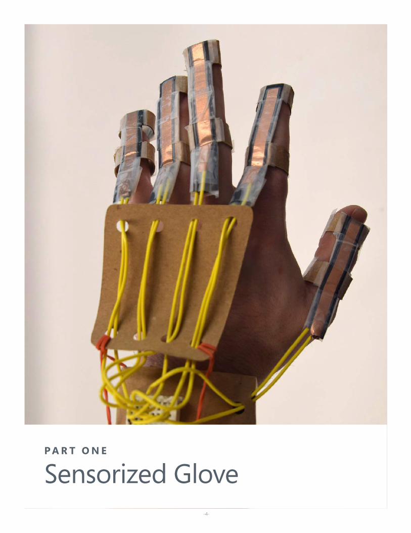
P A R T O N E
Sensorized Glove
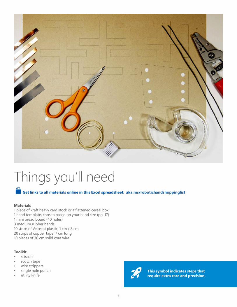
Materials1 piece of kraft heavy card stock or a flattened cereal box1 hand template, chosen based on your hand size (pg. 17)1 mini bread board (40 holes)3 medium rubber bands10 strips of Velostat plastic, 1 cm x 8 cm20 strips of copper tape, 7 cm long 10 pieces of 30 cm solid core wire
Toolkit• scissors• scotch tape• wire strippers• single hole punch• utility knife
Things you’ll need
-5-
Get links to all materials online in this Excel spreadsheet: aka.ms/robotichandshoppinglist
This symbol indicates steps that require extra care and precision.
-6-
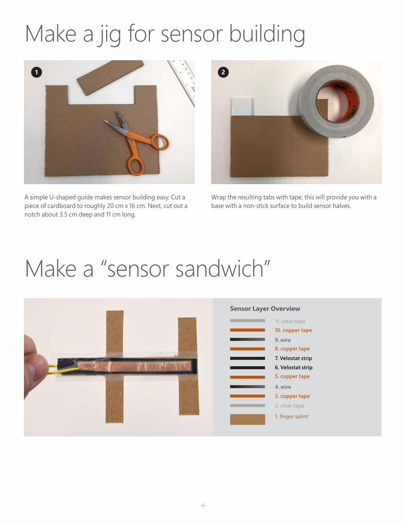
2. clear tape
1. finger splint
7. Velostat strip
3. copper tape
4. wire
5. copper tape
6. Velostat strip
8. copper tape9. wire
10. copper tape
11. clear tape
Sensor Layer Overview
Make a jig for sensor building1 2
A simple U-shaped guide makes sensor building easy. Cut a piece of cardboard to roughly 20 cm x 16 cm. Next, cut out a notch about 3.5 cm deep and 11 cm long.
Wrap the resulting tabs with tape, this will provide you with a base with a non-stick surface to build sensor halves.
Make a “sensor sandwich”
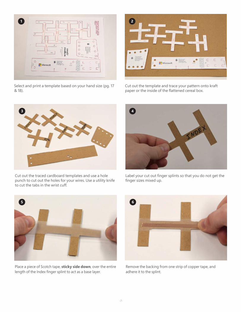
Select and print a template based on your hand size (pg. 17 & 18).
-7-
1 2
Cut out the template and trace your pattern onto kraft paper or the inside of the flattened cereal box.
Cut out the traced cardboard templates and use a hole punch to cut out the holes for your wires. Use a utility knife to cut the tabs in the wrist cuff.
3 4
Label your cut out finger splints so that you do not get the finger sizes mixed up.
Place a piece of Scotch tape, sticky side down, over the entire length of the Index finger splint to act as a base layer.
5 6
Remove the backing from one strip of copper tape, and adhere it to the splint.
-8-
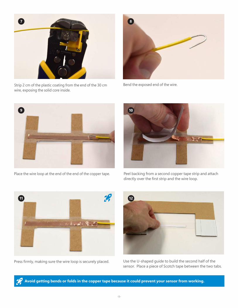
Press firmly, making sure the wire loop is securely placed.
11
Strip 2 cm of the plastic coating from the end of the 30 cm wire, exposing the solid core inside.
7 8
Bend the exposed end of the wire.
Place the wire loop at the end of the end of the copper tape.
9
Peel backing from a second copper tape strip and attach directly over the first strip and the wire loop.
10
12
Use the U-shaped guide to build the second half of the sensor. Place a piece of Scotch tape between the two tabs.
Avoid getting bends or folds in the copper tape because it could prevent your sensor from working.
-9-
13 14
15 16
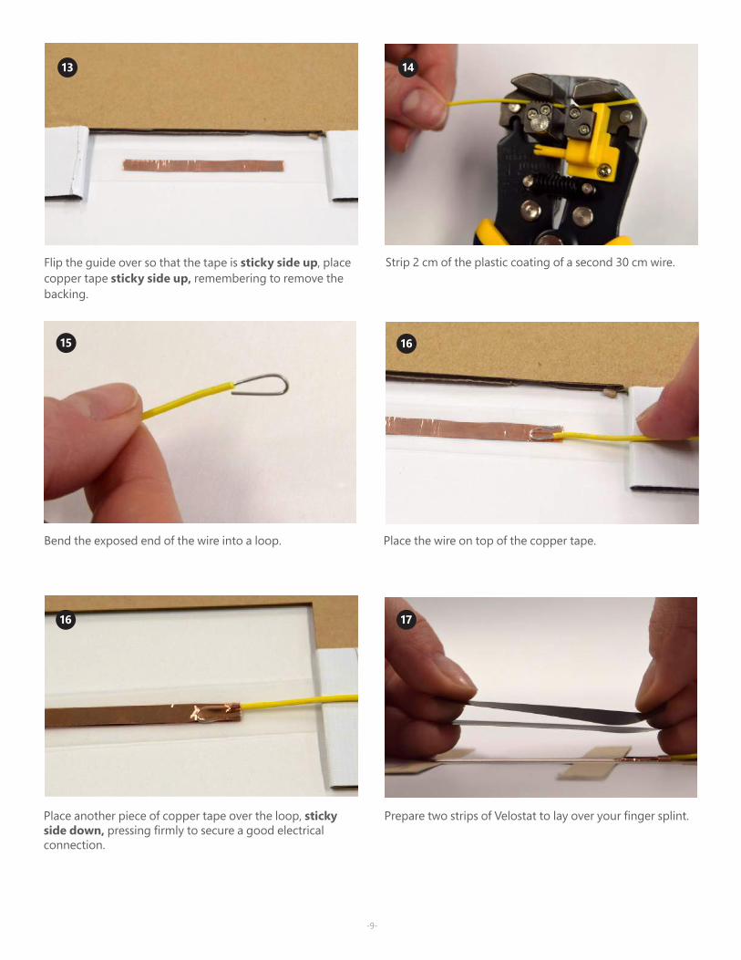
Flip the guide over so that the tape is sticky side up, place copper tape sticky side up, remembering to remove the backing.
Strip 2 cm of the plastic coating of a second 30 cm wire.
Bend the exposed end of the wire into a loop. Place the wire on top of the copper tape.
Place another piece of copper tape over the loop, sticky side down, pressing firmly to secure a good electrical connection.
16 17
Prepare two strips of Velostat to lay over your finger splint.
-10-
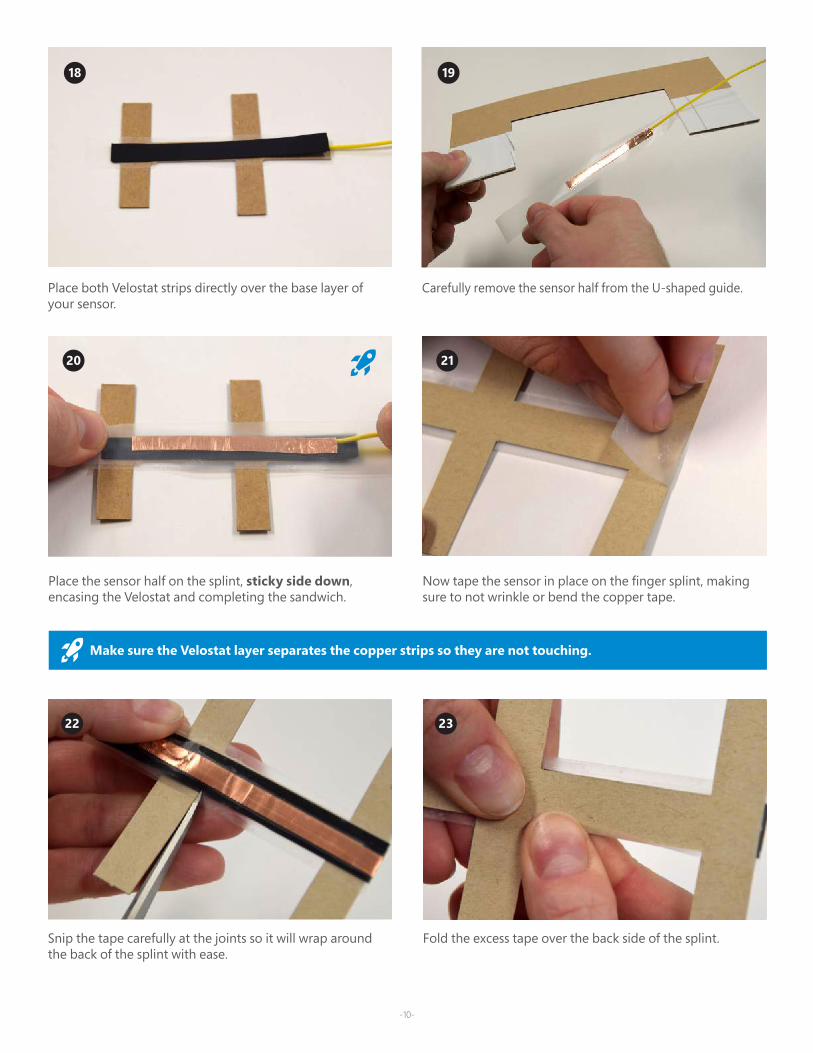
Place both Velostat strips directly over the base layer of your sensor.
Place the sensor half on the splint, sticky side down, encasing the Velostat and completing the sandwich.
18 19
Carefully remove the sensor half from the U-shaped guide.
20 21
Now tape the sensor in place on the finger splint, making sure to not wrinkle or bend the copper tape.
22 23
Snip the tape carefully at the joints so it will wrap around the back of the splint with ease.
Fold the excess tape over the back side of the splint.
Make sure the Velostat layer separates the copper strips so they are not touching.
-11-
24 25
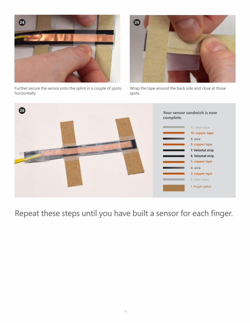
Further secure the sensor onto the splint in a couple of spots, horizontally.
Wrap the tape around the back side and close at those spots.
2. clear tape
1. finger splint
7. Velostat strip
3. copper tape
4. wire
5. copper tape
6. Velostat strip
8. copper tape9. wire
10. copper tape
11. clear tape
Your sensor sandwich is now complete.
26
Repeat these steps until you have built a sensor for each finger.
-12-
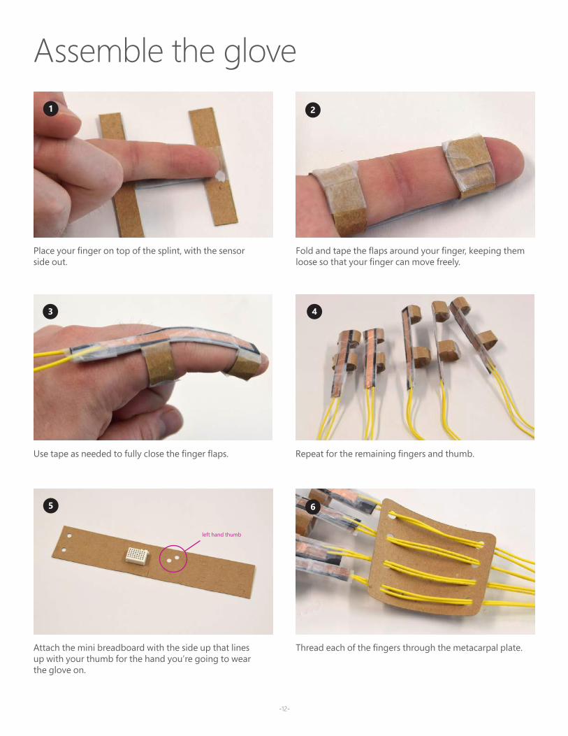
Assemble the glove
Repeat for the remaining fingers and thumb.
Place your finger on top of the splint, with the sensor side out.
1
Fold and tape the flaps around your finger, keeping them loose so that your finger can move freely.
2
43
Use tape as needed to fully close the finger flaps.
Attach the mini breadboard with the side up that lines up with your thumb for the hand you’re going to wear the glove on.
5
Thread each of the fingers through the metacarpal plate.
6
left hand thumb
-13-
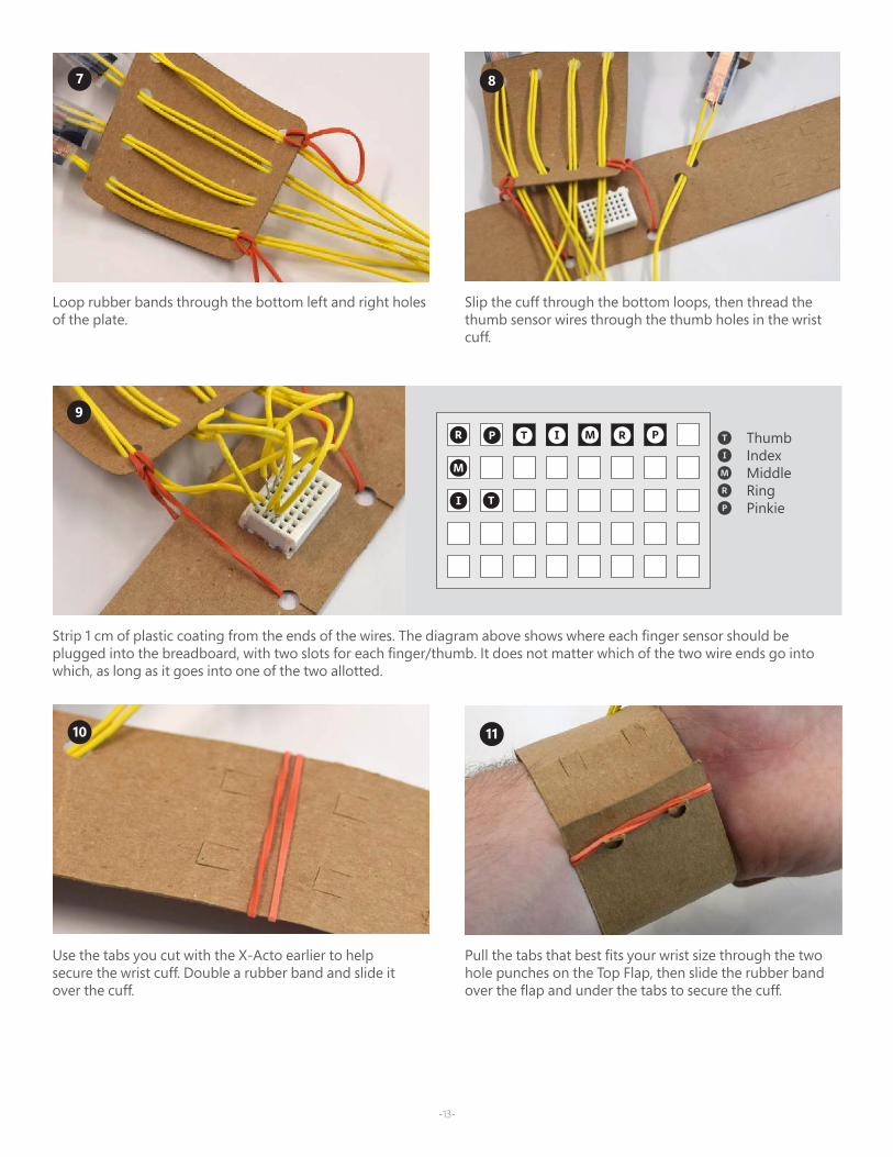
Loop rubber bands through the bottom left and right holes of the plate.
7
Slip the cuff through the bottom loops, then thread the thumb sensor wires through the thumb holes in the wrist cuff.
8
9
Strip 1 cm of plastic coating from the ends of the wires. The diagram above shows where each finger sensor should be plugged into the breadboard, with two slots for each finger/thumb. It does not matter which of the two wire ends go into which, as long as it goes into one of the two allotted.
Use the tabs you cut with the X-Acto earlier to help secure the wrist cuff. Double a rubber band and slide it over the cuff.
10
Pull the tabs that best fits your wrist size through the two hole punches on the Top Flap, then slide the rubber band over the flap and under the tabs to secure the cuff.
11
-14-
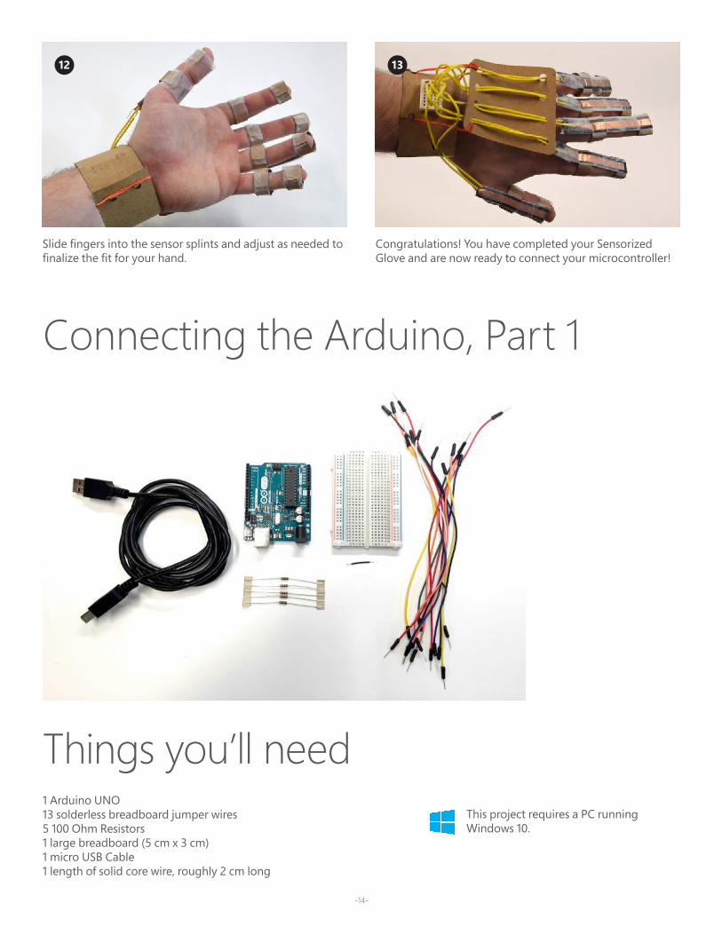
1 Arduino UNO 13 solderless breadboard jumper wires5 100 Ohm Resistors1 large breadboard (5 cm x 3 cm)1 micro USB Cable1 length of solid core wire, roughly 2 cm long
Things you’ll need
Connecting the Arduino, Part 1
Slide fingers into the sensor splints and adjust as needed to finalize the fit for your hand.
12
Congratulations! You have completed your Sensorized Glove and are now ready to connect your microcontroller!
13
This project requires a PC running Windows 10.
-15-
Next, select: Tools > Port > COM4 (Arduino UNO) noting that your particular com port may be different than COM4.
2
3
Then select Tools > Board: “Arduino/Genuino Uno” > Arduino UNO.
Connect your Arduino to your computer with the micro USB cord. Next, you will need to install the Arduino IDE which you can access through the Technical Requirement link on the Hand lesson page at aka.ms/hackingSTEM or directly through the Microsoft Store. Follow the prompts to success-fully complete installation.
1
4
Go to https://aka.ms/biomechanicsarduinocode and down-load the flash code.
6
Locate and open your downloaded file to launch the Arduino application.
Click on the circular right arrow button to upload.
5

87 Take your short length of wire, strip at both ends, and insert as a jumper wire on your glove mini-breadboard, as shown below.
Connect 6 solderless wires between the mini-breadboard on your glove and the large breadboard. The color of the wires can be helpful but does not impact the functionality.
9 Place the 5 Ohm Resistors on the breadboard as shown above. You can trim the ends if you want them to sit closer to the board.
10 Connect the other 7 solderless wires between the Arduino UNO and the large breadboard.
7
8
9
10
Congratulations!You are now ready to move onto the Robotic Hand activity (pg. 19) or plug into the custom Excel Workbook (pg. 33) and visualize data!

-17-
Thumb
Ring
In
dex
Pinkie
Middle
This
side
up
for
mak
ing
a le
ft
hand
. Rev
erse
to
use
the
right
han
d.
Top flap
Bottom flap
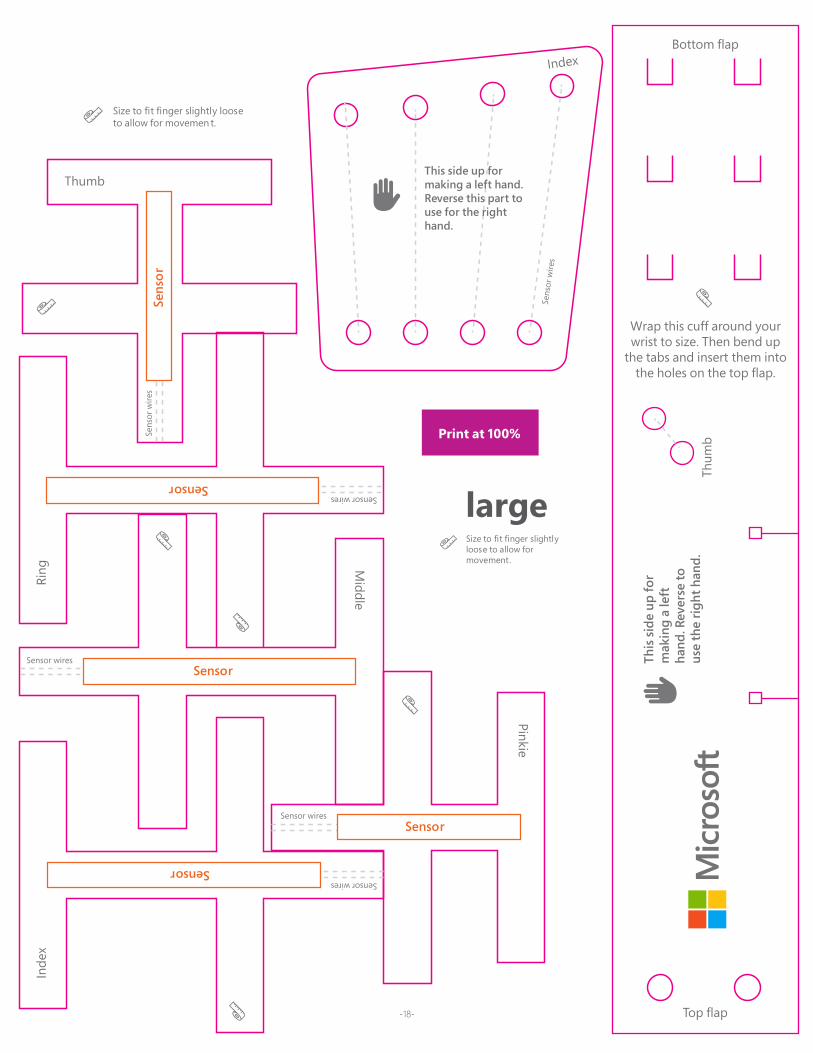
Wrap this cuff around your wrist to size. Then bend up
the tabs and insert them into the holes on the top flap.
This side up for making a left hand. Reverse this part to use for the right hand.
small/medium
Se
nsor
wire
s
Index
Size to fit finger slightly loose to allow for movement.
Thum
bSens
or w
ires
Sensor wires
Sensor wires
Sensor wiresSensor
Sensor
Sensor
Sensor wiresSensor
Sens
or
Print at 100%
-18-
Thumb
Ring
In
dex
Pinkie
Middle
This
side
up
for
mak
ing
a le
ft ha
nd. R
ever
se to
us
e th
e rig
ht h
and.
Top flap
Bottom flap
Wrap this cuff around your wrist to size. Then bend up
the tabs and insert them into the holes on the top flap.
This side up for making a left hand. Reverse this part to use for the right hand.
large
Sens
or
wire
s
Index
Size to fit finger slightly loose to allow for movemen t.
Thum
bSens
or w
ires
Sensor wires
Sensor wires
Sensor wiresSensor
Sensor
Sensor
Sensor wiresSensor
Sens
or
Size to fit finger slightly loose to allow for movement.
Print at 100%
-19-
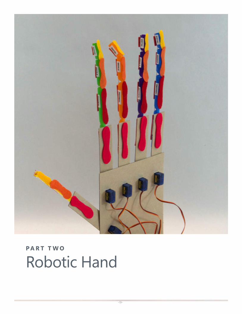
P A R T T W O
Robotic Hand
-20-
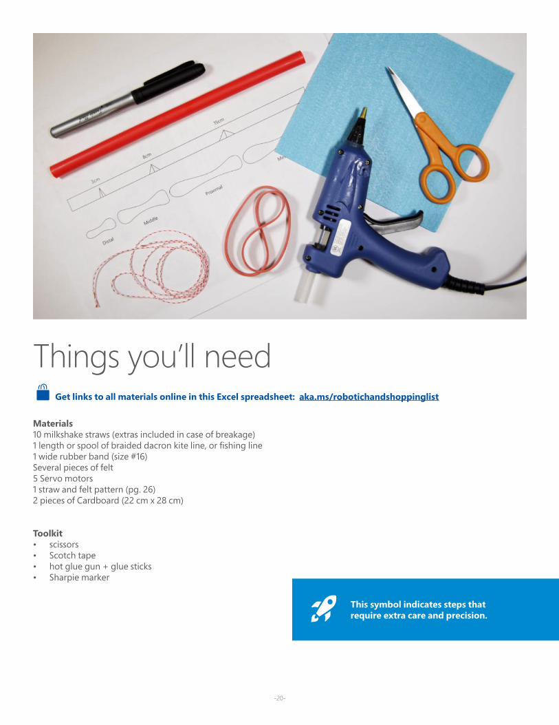
Materials10 milkshake straws (extras included in case of breakage)1 length or spool of braided dacron kite line, or fishing line 1 wide rubber band (size #16)Several pieces of felt5 Servo motors1 straw and felt pattern (pg. 26)2 pieces of Cardboard (22 cm x 28 cm)
Toolkit• scissors• Scotch tape• hot glue gun + glue sticks• Sharpie marker
Things you’ll need Get links to all materials online in this Excel spreadsheet: aka.ms/robotichandshoppinglist
This symbol indicates steps that require extra care and precision.
-21-
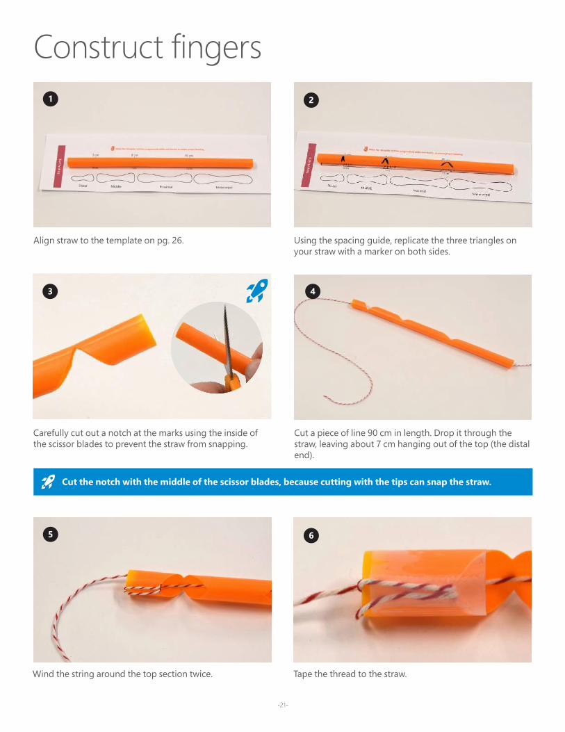
Construct fingers1 2
43
5 6
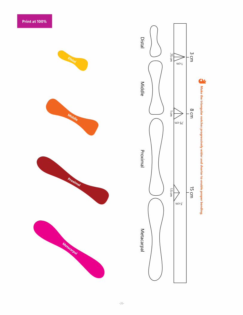
Align straw to the template on pg. 26. Using the spacing guide, replicate the three triangles on your straw with a marker on both sides.
Carefully cut out a notch at the marks using the inside of the scissor blades to prevent the straw from snapping.
Cut a piece of line 90 cm in length. Drop it through the straw, leaving about 7 cm hanging out of the top (the distal end).
Cut the notch with the middle of the scissor blades, because cutting with the tips can snap the straw.
Wind the string around the top section twice. Tape the thread to the straw.
-22-
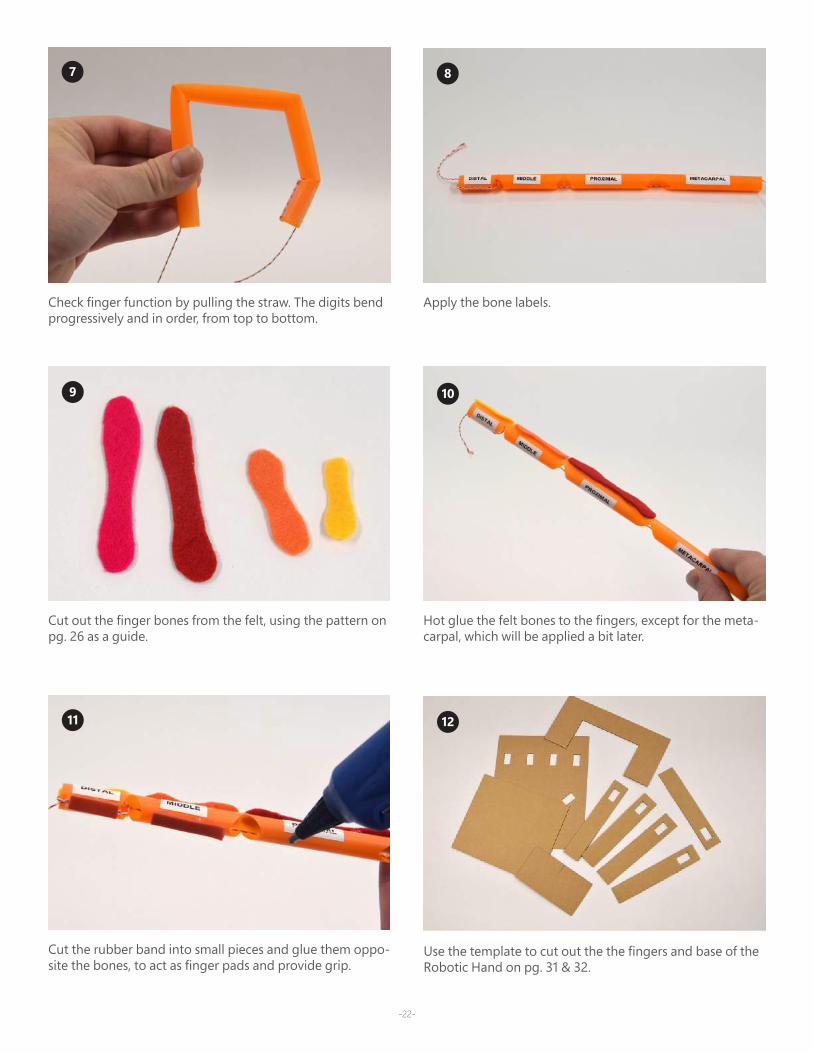
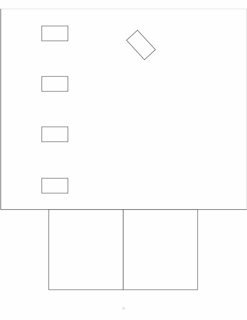
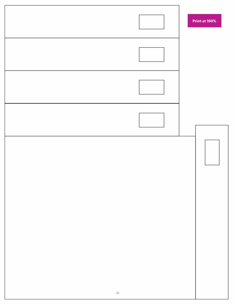
Use the template to cut out the the fingers and base of the Robotic Hand on pg. 31 & 32.
Apply the bone labels. Check finger function by pulling the straw. The digits bend progressively and in order, from top to bottom.
7 8
9 10
11 12
Hot glue the felt bones to the fingers, except for the meta-carpal, which will be applied a bit later.
Cut out the finger bones from the felt, using the pattern on pg. 26 as a guide.
Cut the rubber band into small pieces and glue them oppo-site the bones, to act as finger pads and provide grip.
-23-
13 14
15 16
17 18
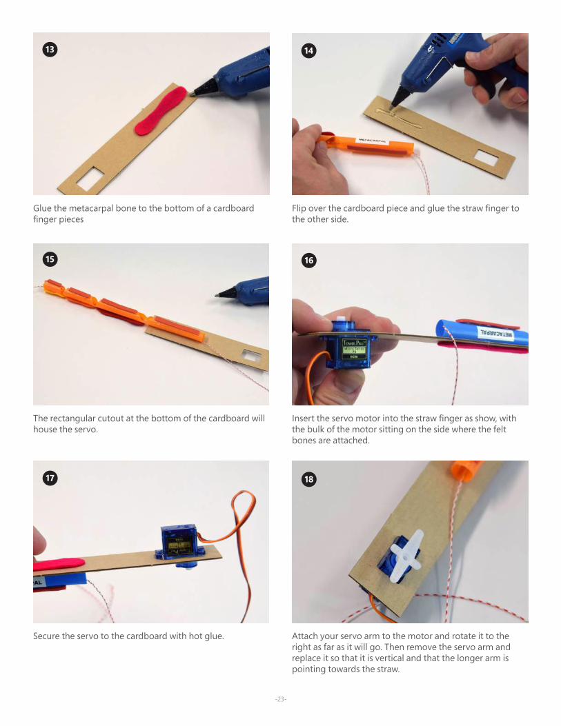
Flip over the cardboard piece and glue the straw finger to the other side.
Glue the metacarpal bone to the bottom of a cardboard finger pieces
Insert the servo motor into the straw finger as show, with the bulk of the motor sitting on the side where the felt bones are attached.
The rectangular cutout at the bottom of the cardboard will house the servo.
Attach your servo arm to the motor and rotate it to the right as far as it will go. Then remove the servo arm and replace it so that it is vertical and that the longer arm is pointing towards the straw.
Secure the servo to the cardboard with hot glue.
-24-
19 20
21 22
23 24
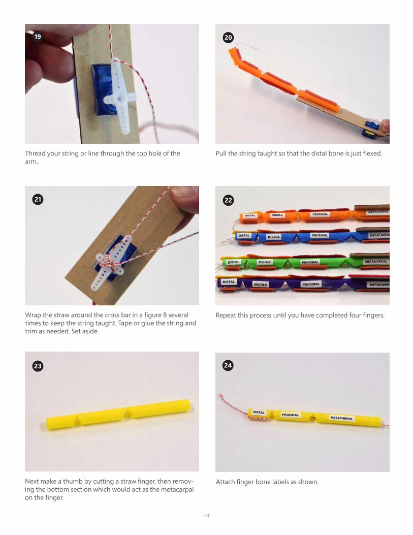
Pull the string taught so that the distal bone is just flexed. Thread your string or line through the top hole of the arm.
Wrap the straw around the cross bar in a figure 8 several times to keep the string taught. Tape or glue the string and trim as needed. Set aside.
Next make a thumb by cutting a straw finger, then remov-ing the bottom section which would act as the metacarpal on the finger.
Repeat this process until you have completed four fingers.
Attach finger bone labels as shown.
25 26
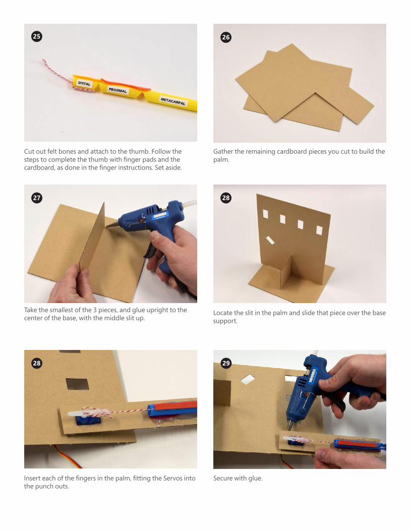
Cut out felt bones and attach to the thumb. Follow the steps to complete the thumb with finger pads and the cardboard, as done in the finger instructions. Set aside.
27 28
Gather the remaining cardboard pieces you cut to build the palm.
Take the smallest of the 3 pieces, and glue upright to the center of the base, with the middle slit up.
Locate the slit in the palm and slide that piece over the base support.
28
Insert each of the fingers in the palm, fitting the Servos into the punch outs.
29
Secure with glue.
-26-
Distal
Middle
Proximal
Metacarpal
3 cm8 cm
15 cm
.75 cm
1 cm
1 cm
.75 cm
1.5 cm
.5 cm
Make the triangular notches progressively w
ider and shorter to enable proper bending.
Distal
Middle
Proximal
Metacarpal
Print at 100%
-27-
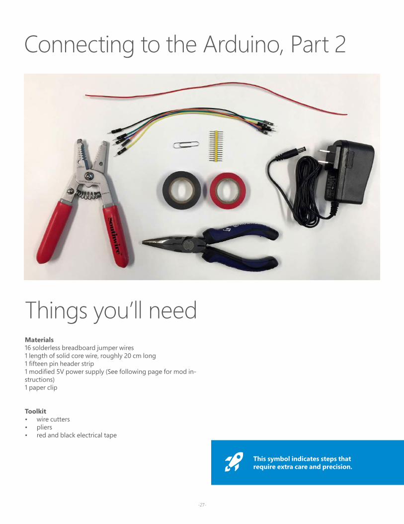
Things you’ll needMaterials16 solderless breadboard jumper wires1 length of solid core wire, roughly 20 cm long1 fifteen pin header strip1 modified 5V power supply (See following page for mod in-structions)1 paper clip
Toolkit• wire cutters• pliers• red and black electrical tape
Connecting to the Arduino, Part 2
This symbol indicates steps that require extra care and precision.
-28-
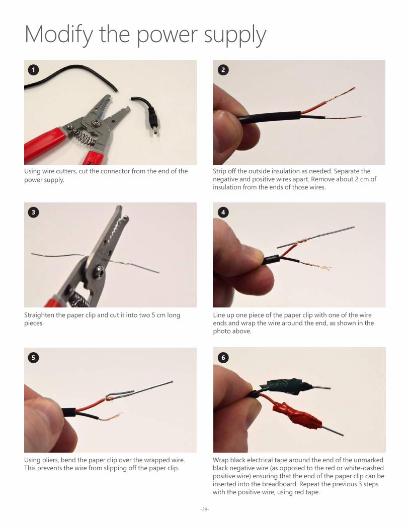
Modify the power supply
Using wire cutters, cut the connector from the end of the power supply.
Straighten the paper clip and cut it into two 5 cm long pieces.
Line up one piece of the paper clip with one of the wire ends and wrap the wire around the end, as shown in the photo above.
Using pliers, bend the paper clip over the wrapped wire. This prevents the wire from slipping off the paper clip.
Wrap black electrical tape around the end of the unmarked black negative wire (as opposed to the red or white-dashed positive wire) ensuring that the end of the paper clip can be inserted into the breadboard. Repeat the previous 3 steps with the positive wire, using red tape.
Strip off the outside insulation as needed. Separate the negative and positive wires apart. Remove about 2 cm of insulation from the ends of those wires.
1
3
5
2
4
6
-29-
1
1 2
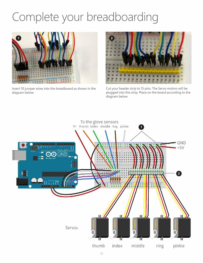
Insert 10 jumper wires into the breadboard as shown in the diagram below.
Cut your header strip to 15 pins. The Servo motors will be plugged into this strip. Place on the board according to the diagram below.
2
Complete your breadboarding
-30--30-
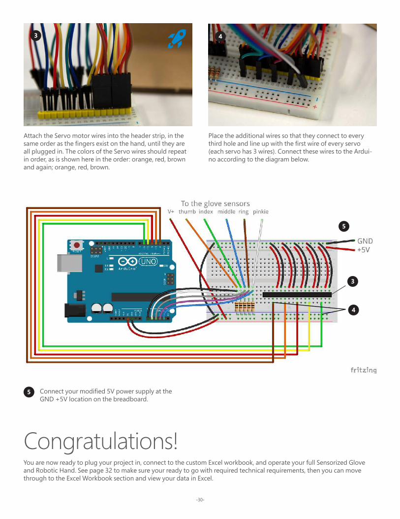
Attach the Servo motor wires into the header strip, in the same order as the fingers exist on the hand, until they are all plugged in. The colors of the Servo wires should repeat in order, as is shown here in the order: orange, red, brown and again; orange, red, brown.
3 4
Place the additional wires so that they connect to every third hole and line up with the first wire of every servo (each servo has 3 wires). Connect these wires to the Ardui-no according to the diagram below.
4
3
5
5 Connect your modified 5V power supply at the GND +5V location on the breadboard.
Congratulations! You are now ready to plug your project in, connect to the custom Excel workbook, and operate your full Sensorized Glove and Robotic Hand. See page 32 to make sure your ready to go with required technical requirements, then you can move through to the Excel Workbook section and view your data in Excel.
-31-
-32--32-
Print at 100%

-33-
Get ready to visualize dataTo complete the full project, make sure you meet these technical requirements:
• PC running Windows 10, and Excel 2016 (Desktop)• Project Cordoba Add-In: Modernize your existing copy of Microsoft Excel 2016 with a free add-in to support real-time
data streaming from your projects available at: aka.ms/getaccess• Customized Excel Workbook available at: aka.ms/biomechanicsworkbook
Hand Visualization
Get started by selecting Left or Right for your gloved hand. As you move your fingers, you should see the movement approximated on the plot.
Phalanyx Flexion
Details on incoming data are provided in a corresponding table, beginning with the Phalanx Flexion. 100% represents a Full Flexion. For example, a closed fist with all fingers fully flexed would be represented by all five fingers having 100% flexion. Alternatively a fully open hand with all fingers fully extended would be represented by all five fingers having 0% flexion .
In real-time, the tops of each phalanx bone in the Hand Visualization are reflected and approximated in the XY coordinates portion of the table.
Excel workbook basics

-34-
Rock, Paper, Scissors ExtensionWith your glove connected to the Project Cordoba add-in, you can play Rock, Paper, Scissors (RPS) with Excel.
Game basics
The sensorized glove you have created and connected to the excel worksheet can be found on the left side of the worksheet while Excel’s hand gestures are represented on the right. An RPS match will consist of 5 rounds. In each round you will see the message sequence “Ready”, “Set”, “GO!”. When “GO!” appears, throw your RPS gesture.
RPS game history
The rounds will be shown below the hand visualization while the match number can be found in the between the two hand visualizations (Note: if your gesture cannot be determined, the round will end as a tie). The history of the gestures thrown in the current match’s rounds can been seen below the main hand diagram areas. After 5 rounds, the winner of the match will be the player (you or Excel) with more round wins. Details on prior matches are also available at the bottom of the worksheet.