building instructions folding crane
TRANSCRIPT

Building Instructions Folding Crane

T S R
Q
NM L
I F
J K G+H
V E D
U C B
A
Construction manual folding crane Basic version
Parts list:
A 1 swing cylinder 270 degrees
B 1 crane mounting plate
C 1 clamping plate
D 1 crane receptacle
E 1 1st arm
F 1 2nd arm
G 1 holding hook
H 2 spacer plates
I 1 kinematics log
J 2 kinematics arms short K 2 kinematics arms long
L 1 Cylinder holding plate straight
M 1 Cylinder support plate bent (only basic version)
N 1 telescopic arm (pre-assembled)
Q 1 cylinder telescope
1 cyl. Telescope. with side Holes R 1 hose holder 4 times
S 1 hose holder 6 times m. mounting hole T 1 hose holder 2 fold
1 hose holder 2 times m. mounting hole U 1 lifting cylinder 1st Arm 14/60 M3
V 1 lifting cylinder 2nd arm 14/50 M3 hydraulic accessories:
2 Y-pieces 3mm
22 securing sleeves H 020
4 securing sleeves H 021
1 pump with motor and tank 1 control valve 4 times
5.5 m hose H 052
0.5 m hose H 058
250 ml of hydraulic oil
screws: 4 Din 7985 M3x6 2 Din 7985 M3x10 1 Din 965 M3x6 1 Din 913 M5x6 4 Din 7985 M3x4 8 Din 7380 M3x6 8 Din 7380 M3x5 1 Din 7985 M3x12 1 Din 985 M3 2 Din 7985 M2x8 2 Din 965 M2x5 4 Din 965 M2x6 1 Din 7985 M2x12 4 Din 934 M2 1 Din 985 M2 1 Din 7985 M1.6x8 1 Din 7985 M1.6x6 1 Din 934 M1.6 6 Din 913 M3x3 1 Din 913 M3x5 2 Din 915 M3x3 6 Din 705 4mm 10 Din 988 4x8x1 2 Din 988 4x8x0.5 2 Din 988 3x6x1 2 Din 125 2.2 1 brass bushing 3x5, 5lg 2 bolts 4x28 1 bolt 4x25 2 bolts 4x22 3 bolts 4x18 2 cable ties small

Din988
Screws, bolts, washers, lock washers,
Din 84
Din427
Din933
Din934
Din471
Din705
Din912
Din 6799
Din913
Din 965

Screws, bolts, washers, lock washers,
ISO 7380
Din7516
Din 7981
Din 7985

Bild 1
Bild 2
Bild 3
Bild 4
Please look for the swivel cylinder (A), the crane mounting plate (B), the screw Din7985 M3x6 and the screw Din 965 M3x6 from the kit .
Attach the plate (B) to the swing cylinder as shown in Figure 2. The sheet (B) is flush with the swivel cylinder foot. Now you need the crane support (D), the 1st arm (E), the grub screw Din 913 M5x6 and the 4 screws Din 7985 M3x4. Screw the first arm (E) and the crane support (D) with the 4 screws Din 7985 M3x4. The opening in the crane frame (D) and the 1.Arm must point in the same direction.

Bild 5
Bild 6
Bild 7
Bild 8
Now you need the 2nd arm (F), the retaining hook (G), the 2 spacer plates (H), the hose holder 6-fold with mounting hole, 2 screws Din 7985 M2x8, 2 nuts Din 934 M2, 1 screw Din 7985 M1.6x8 and 1 nut Din 934 M1.6
Now attach the 2 spacer plates (H) and the retaining hook (G) to the second arm (F) with the screws Din 7985 M2x8 and the nuts Din 934 M2, as shown in picture 6.
In the required part of the second arm (F) the hose holder (S) is fastened with the screw Din 7985 M1,6x8 and the nut Din 934 M1,6. The screw head up the nut to the hose holder (S). Important NOTE: The hose holders are intentionally drilled very tight, so that a good guidance of the hoses is achieved! To facilitate threading the hose into the holder, you should cut the hose end at an angle.
In the next step you need: telescopic arm (N) Kinematikklotz (I) Cylinder holding sheet straight (L) Cylinder holding sheet bent (M) Hose holder 2-fold (T) with mounting hole 4 screws Din 965 M2x6 2 screws Din 965 M2x5 with nuts Din 934 M2 1 screw Din 7985 M1,6x6

Bild 9
Bild 10
Bild 11
Bild 12
Now take the kinematics block (I) and search the kinematics arms briefly (J), the bolt 4x22, the 2 screws Din 7380 M3x5 and the 2 fitting discs Din 988 4x8x1 from the kit.
Insert the 4x22 bolt through the second hole (see Fig. 10) and thread a fitting disc Din 988 4x8x1 on both sides and a kinematic arm each short (J). Finally, screw the arms with the 2 screws Din 7380 M3x4. The hose holder 2-fold with fixing bore (T) is fastened with the screw Din 7985 M1,6x6 on the kinematic block (I).
Pull the inner telescopes out of the arm and fix the block (I) with 4 screws Din 965 M2x6. Use the larger holes to reach the screws with the screwdriver. After installation, please feel with your finger whether the screws do not protrude so that the inner telescopes do not grind against the screw heads.
Insert the 2 Din 965 M2x5 screws from the inside into the rear holes of the telescopic arm and hold them with one finger. The screw heads must not protrude out of the countersinks, otherwise the telescopes will not be able to slide past. Now thread the cylinder holding plates (M) and (L) on the protruding screws and fasten them each with a nut Din 934 M2. If you have purchased the optional hydraulic extension, the hose retaining plate (B) is mounted from the hydraulic extension instead of the cylinder retaining plate (M). (See picture 1 hydr. Then gently push the two inner telescopes back

into the telescopic arm.
Bild 13
Bild 14
Bild 15
Bild 16
For the next step you need: the telescopic arm Cylinder telescope (Q)
Cylinder telescope with side. Holes (Q) Screw Din 7985 M2x12 Stop nut Din 985 M2
Brass sleeve 3x5, 3lg (not shown) 2 washers Din 125 2.2 (not delivered) 2 grub screws with shoulder Din 915 M3x3 screw Din 7985 M3x6 Screw Din 7985 M3x12
Stop nut Din 985 M3 (not shown) 2 washers Din 988 3x6x1
First, screw a grub screw Din 915 through the small, angular part of the cylinder ring on the second telescope until it projects slightly into the round part with the heel. Plug that in Cylinder Telescope with hole (Q) on the grub screw so that the shoulder threads into the hole. On the opposite side, screw in the other grub screw until you thread it into the hole as well. Adjust the cylinder exactly in the center of the cutout.
Now insert the brass sleeve into the cylinder eye and fix it with the Din 7985 M2x12 screw, one Din 125 2.2 U-washer next to the cylinder ring and the Din 985 M2 stop nut on the required cylindrical ring in the cut-out with the oblong hole. Before tightening the screw properly, adjust the height of the cylinder so that it is exactly parallel to the telescopic arm, even when the telescope is inserted.
Now fasten the other cylinder telescope (Q) with the screw Din 7985 M3x12, the two washers Din 988 3x6x1 and the stop nut Din 985 M3, as shown in picture 16, between the cylinder holding plates (L) and (M). If the cylinder is not exactly parallel to the arm, the shims may need to be redistributed.

Bild 17
Bild 18
Bild 19
Bild 19a
Screw the other side of the cylinder to the cylinder ring of the 2nd telescope with the screw Din 7985 M3x6. Now you need: the telescopic arm (N) the 2nd arm (F) 1 bolt 4x28 1 bolt 4x18 4 screws Din 7380 M3x5 4 washers Din 988 4x8x1 2 washers Din 988 4x8x0,5 2 kinematics arms long (K) The other pictured parts have already been attached to the kinematics block (I).
Insert the bolt 4x28 through the upper, drilled hole of the second arm (F) (see picture 19) and thread 2 dia. Disks Din 988 4x8x1 and 1 kinematik arm long (K) on each side. Now screw the arms with 1 screw each Din 7380 M3x5 per side. For further assembly you need the following parts: 1 bolt 4x18 2 washers Din988 4x8x0.5 2 screws Din 7380 M3x5 1 kinematics log

Bild 19b
Bild 19c
Bild 19d
In a kinematic-block the bolt 4x18 is pushed.
On the bolt is pushed on each side a washer 4x8x0.5.
The thus prepared kinematics block is pushed between T he legs of the second arm.
Bild 19e
Bild 20
The bolt is secured with 2 screws Din 7380 M3x5.
So the ready assembled unit should look like this.

Bild 21
Bild 22
Bild 23
Bild 24
Now you need the following parts: the straight connected arms 1 lifting cylinder 2nd arm (V) 1 bolt 4x28 4 washers Din 988 4x8x1 2 adjusting rings Din 705 4mm 2 grub screws Din 913 M3x3 2 screws Din 7380 M3x5
Now the kinematics are connected to the lifting cylinder (V). To do this, push the 4x28 bolt through the parts in the following order.
Long kinematic arm (K), 2 shims, short kinematics arm (J), collar with grub screw cylinder eye, collar with grub screw, short kinematics arm (J), 2 shims,
Kinematics arm long (K). Please screw with one screw each Din 7380 M3x5 per side.
Adjust the cylinder eye with the adjusting rings exactly in the middle between the arms (J). See picture 22.
To connect the hoses, the cylinder still remains unpaved at the other end. Next you need: the 1st arm (E) 1 bolt 4x25 2 screws Din 7380 M3x5
Please connect the 1st and 2nd arm as shown in picture 24.

Bild 25
Bild 26
Bild 27
Bild 28
After you have put the crane on the swivel cylinder (A) and fixed it with the grub screw you can start with the hose lines. The specified hose lengths take into account a hose path of 25-30 cm from the crane to the control valve! Cut a 40 cm and a 45 cm long piece of tubing Insert both from below through the swivel cylinder and thread one locking sleeve each onto the hose. Connect the longer one to the pressure connection (rear) of the lifting cylinder 1st arm and the other to the tension connection (in the case of the piston rod). Finally, slide the locking sleeves over each connector.
For the lifting cylinder 2nd arm you need 60 cm for the tension side and 54 cm for the pressure side. The pressure connection must still be rotated by 180 °. Push the hose back to the cylinder from below. Observe the hose guide as shown in pictures 26 + 27. Always provide the hoses with securing sleeves and slide them on to secure after connection.
Figure 27 shows the lifting cylinder 2nd Arm already installed. For this you need a bolt 4x18, 2 rings Din 705 4mm with grub screw Din 913 M3x3 and 2 screws Din 7380 M3x6. Please i nsert the bolt through the cylinder eye and adjust it with the adjusting rings exactly in the middle. It is pivoted into the arm only after the hoses for the telescopes have been retracted. For the cylinder telescope (Q) the following pieces of tubing are needed: 1x 3 cm 1x 6.5 cm hose holder 4-fold (R) Y-piece 2 securing sleeves Please connect the hoses as shown in fig. 28. In the hose holder please use the 1st hole.

Now connect a 1m long hose with the free connection
of the Y-piece and insert it through the 3rd opening of
the hose holder. Do not forget the locking sleeve! Now
connect to the cylinder telescope (Q) and secure as
shown in Figure 29.
Screw Din 913 M3x5
Bild 29
Bild 30
Bild 31
Bild 32
For the next step please make the second hose distributor in the same way. See Figure 30. Slip lengths: 1x 4 cm 1x 6 cm 1x 1m for the free end
Figure 31 shows how the connection with the cylinders must be made. Secure all connections. Now thread the hose holder 2-fold (T) (without fixing bore) onto the 2 long hoses and guide through the hose holder on the kinematics block (I) as shown in Fig. 32.

Bild 33
Bild 34
Bild 35
Bild 36
. Now, as shown in Figure 33, guide the hoses through
the kinematics. When the telescope is fully extended,
approximately one such loop should result. The hoses
must never bend
Now push the hoses through the hose holder in the front of the second arm and fasten them to the kinematics block with a small cable tie. In the hose holder please use the 2 outer, lower holes. The 4 upper holes are for the optional extra features. See also Figure 37. Here you can see the hose guide at the joint between the 1st and 2nd arm. If required, you can still secure the 4 hoses with a cable tie around the 4x25 bolt. Now you can fix the lifting cylinder 2nd arm with the 2 screws Din 7380 M3x6. Pay attention to the hoses to pass on both sides of the cylinder and not push it off. See also Figure 38.
When the telescope is inserted, the hose guide should look like Figure 36.

Here you can see again the hose guide in the area of the hose holder 6 times forward in the 2nd Arm.
Bild 37
Bild 38
Bild 39
Hose guide under the lifting cylinder 2. Arm for folding the cylinder. Lastly, the lifting cylinder 1st arm with a bolt 4x22 and 2 screws Din 7380 M3x6 must be attached to the 1st Arm. Please thread the connection In to the cutout of the crane support (D).
Figure 39 shows the fully assembled

two pieces of tubing a`25 cm long. Please cut two pieces of tubing a`25 cm long.
The 25 cm long hoses are pushed with locking sleeves on the two outer connections of the swing cylinder.
This "leak oil connection" does not exist anymore

Amendments
Bild 1
To attach the hydraulic pump to the frame, a "T" sheet is supplied. Parts list: 1 T-plate 2 nuts Din 934 2 screws Din7985 M3 * 6 2 screws Din7985 M3 * 4
The "T" plate is screwed to the pump with 2 screws Din 7985 M3 * 4. The screws Din 7985 M3 * 6 with the nuts then hold the "T" sheet with the pump on the frame.
Bild 2
Figure 2 shows the mounted pump on a semi-trailer.

P from pumpT from pump
Occupancy of the control valve
Support sideways
support
grab
Swivel drive gripper
Telescope
Swing drive crane
Lifting cylinder in the 2nd arm
Lifting cylinder in the 1st arm
Mounting holes of Steuerventisl
Connection of the leak oil line
Further information about the pump and the control valve can be found in the hydraulic instructions.

Bild 40
Bild 41
Now place the entire folding crane at the selected place on the frame and screw it from below with the clamping plate (C), 2 screws Din 7985 M3x6 and 2 screws Din 7985 M3x10 For a better overview, the crane has been removed from the swivel cylinder in the pictures.
Here you can see how the clamping plate (C) is bolted to the crane mounting plate (B) from below. The 2 screws Din 7985 M3x6 are to be used for the left-hand screwed connection (see picture 41).
Figure 42 shows The folding crane mounted on the vehicle.
Bild 42

Installation instructions for the model hydraulics hydraulic pump
The two connections on the tank of the pump are used for venting and for filling the oil.
If you need to transport a model, you should hose-connect these two ports.
The oil level can be monitored through the PVC lid of the pump tank
Here you can see how the oil is filled in the pump. Never fill the pump completely with oil, but only to about 3/4. (See also: "Notes on commissioning")
There are two connections on the pump body. The left port (labeled "P") provides the pressure oil, the right-hand port labeled "T" directs the oil back into the tank.
The included oil filter ensures that the oil is kept clean and should always be placed in the pressure line.
Which connection of the filter is used as "input" or "output" does not matter. If necessary, a pressure gauge can be connected to the " blind screw" in the filter. (see chapter "Pressure adjustment")
*
T P
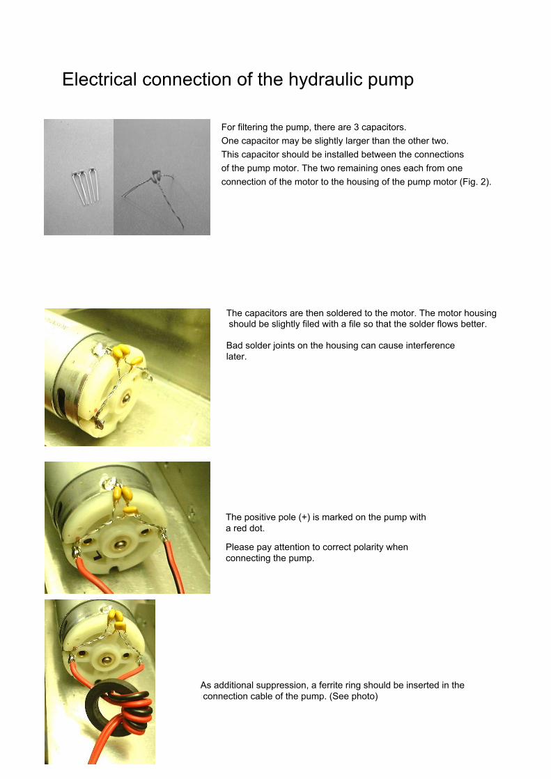
Electrical connection of the hydraulic pump
For filtering the pump, there are 3 capacitors.
One capacitor may be slightly larger than the other two.
This capacitor should be installed between the connections
of the pump motor. The two remaining ones each from one
connection of the motor to the housing of the pump motor (Fig. 2).
The capacitors are then soldered to the motor. The motor housing should be slightly filed with a file so that the solder flows better.
Bad solder joints on the housing can cause interference later.
The positive pole (+) is marked on the pump with a red dot.
Please pay attention to correct polarity when connecting the pump.
As additional suppression, a ferrite ring should be inserted in the connection cable of the pump. (See photo)

Connection of a pressure gauge
On the filter unit is a blind screw with seal.
Take this screw out.
. A nipple (supplied with the pressure gauge) is screwed into the hole and with a little hose (also included in the pressure gauge set) connected. All hose connections must be secured with safety sleeves.
After completion of the pressure setting, the pressure gauge becomes removed with the hose and the blind screw inserted again.
J

Pressure adjustment on the hydraulic pump
First turn the screw plug on the side of the pump body completely out.
From the hole of the adjusting screw is expected during the adjustment work with oil leakage.
Screw
Behind the plug is a grub screw with TORX-7. (before 2004 a grub screw with key width 2.5mm) Run the pump and turn the grub screw: - clockwise increases the pressure - counterclockwise the pressure drops Carefully turn the adjustment screw; the adjustment range is only distributed about 1/4 turn Be careful, if the adjustment screw is screwed in or out too far, the pressure limiter unit may become ineffective and the pump will not be able to pressurize. � The pump is set at the factory to approx. 10 bar. A higher pressure leads to increased wear in the pump and thus to a loss of warranty.

Control valve
The side view of the control valve shows two connections. The connection "P" is connected to the pump via the filter unit and carries the
pressure oil. The connection "T" is connected to the connection "T" of the pump. Above that, the returning oil gets back into the tank.
Screws Interchanging the connections "P and T" leads to leaks and malfunctions!
� The eccentric of the control valve are factory set to zero point and fixed with knurled screws. Please do not turn the thumbscrews before mounting the servos
On the control valve there are the connections "A and B", to each of which a control function (cylinder) is connected. (See also chapter: "Notes on hose routing")
The rubbers included in the scope of delivery of the servo must be mounted, otherwise the servo sits too low,
Please align the servo as shown in picture 36. The rubber grommets and the brass sleeves are inserted into the servo fixing flanges.

The arms included with the servo must be shortened as shown in the picture.
Then the shortened arms are inserted into the eccentric of the control valve
Repeat this procedure for all hydraulic functions until all eccentrics equipped with a servo arm.
Now the servos have to be moved to their basic position. To do this, please connect the servos to your receiver, and then turn on remote control system and receiver.
Please note that receivers, as well as servos never directly to the 12V battery of the model may be connected. If not observed, it will destroy all servos and the receiver!
The receiver and the servos in a model are usually powered by the receiver cable of a cruise control with integrated voltage regulator or a separate receiver battery. If available, a power supply with an output voltage of 4.7V to 5V can be used
. After switching on the remote control and receiver, please set all sticks and sliders, with which hydraulic functions are to be operated in the middle position.

If necessary, select which servo should be used for which function. Now the servos are in their future basic position and can be mounted with 2 screws (supplied with the control valve).
. After mounting the servos, please remove the thumbscrews.
Never operate a servo for a hydraulic function that
is still secured with a knurled screw. Failure to do so can destroy the servo! . Please keep the thumbscrews.
They are needed when a servo is replaced or the zero point of a hydraulic function must be reset.
If you are retrofitting a hydraulic function, you must connect the additional control valve to your existing one.
For this, the two "P" ports and the two "T" ports of the control valves must be used be connected with T or Y pieces. These are then connected to "P" or "T" of the pump again.
For a small additional charge, we can also attach the additional control valve to your existing control block
If a servo has to be replaced or the zero point of a hydraulic function
has to be readjusted, Please proceed as follows:
- - Screw a knurled screw into the hydraulic function, at which the servo must be replaced or the zero point set.
- - Unscrew the servo of the corresponding function. - - The knurled screw can now be used to reset the zero point by
turning the knurled screw until the cylinder of the hydraulic function stops moving.
If necessary, turn the knurled screw once more until the cylinder moves again, and then back slightly to set the middle of the "zero range". because the control valve can usually have a slightly wider "zero range"If necessary, connect the old / new servo to the receiver in order to move it to the home position. - (The stick / slide switches and trims of the relevant hydraulic function should be in the middle position) - - Now the old or new servo (again) can be mounted.
Do not forget to remove the knurled screw after installing the servo!

Hose fitting
On the hose, a safety sleeve is first pushed.
Then the tube is pushed to about halfway onto the nipple.
Please do not use pliers, to push the locking sleeve onto the nipple. This can easily damage the hose or even break the nipple
Tip: Please always slide the locking sleeves with your fingers. To protect the fingers you can use a handkerchief or a cloth.
The locking sleeve should be pushed all the way to the nipple.

Loosen hose fittings
Please pull the safety sleeve off the nipple To protect the fingers you can use a handkerchief or a cloth.
Please do not use a pair of pliers to pull the locking sleeve from the nipple.
This can easily damage the hose or even break the nipple.
With a pair of pliers, the hose is first cut on the side of the nipple.
Alternatively, you can use a knife to cut the hose
sideways.
Please cut the hose Never use a knife in the longitudinal direction.
Now it is easy to remove the hose.
The previously cut piece of hose must be pushed back before one
of the hose are cut off.

Notes on hose routing
The connection "P" of the pump is connected to the oil filter.
The oil filter outlet is connected to port "P" of the control valve.
The port "T" of the control valve is connected to port "T" of the pump.
The non-pressurized return line needs no securing sleeves
The cylinder is connected to one port each "A" and "B". If several cylinders are switched in parallel, In each case, the top and bottom of the cylinders must first be connected with T or Y pieces.

Maintenance
The cylinder is connected to one port each "A" and "B". If several cylinders are switched in parallel, In each case, the top and bottom of the cylinder must first be connected to T or Y pieces.
If no oil change is carried out over a longer period of time abrasion accumulates in the hydraulic oil, which acts like emery paper when circulating in the system and leads to increased wear on the pump, cylinders and control valve.
Insufficient maintenance can lead to a loss of warranty for the entire hydraulic system!
The tank of the pump is withdrawn by a rotating and pulling movement of the pump body.
To clean the empty tank, e.g. with benzene or spirit.
� The old oil should be taken to your local Recycling centre.
Use only the oil supplied with the hydraulics!
To open the filter unit you need a 27mm spanner If you do not have an open-end wrench on hand, it also does a pair of pliers.
Unscrew the filter.
If there is an angled nipple on the filter, it can be unscrewed from the filter without removing the hose from the nipple.
4

Inside is the filter element. Please also unscrew this with a large slotted screwdriver.
Please also clean the filter parts with benzene or spirit.
If the filter insert has already been cleaned several times, or is heavily soiled, this is available as a spare part with the order no. H055N
If your filter insert does not look exactly as it is in the photo, it may be that you have an older style filter. In this case, the order no. H055A
After cleaning, please put the tank back on the pump and reassemble the filter. But do not re-install it firmly in your model. Now fill the pump about 2/3 with oil and put your model back into operation. Please press all hydraulic functions several times. (This rinses the old oil from the cylinders and the control valve) Repeat this procedure until the oil in the tank stays clean.

Notes on commissioning
Please connect the servos to your remote control system (if not already done). Fill the oil tank about 3/4 with hydraulic oil. Use only the oil supplied with the hydraulics! For initial start-up, connect the pump to a voltage of approximately 4.7V to 8V. (Due to the lower voltage, the oil-air mixture enters the tank more slowly and thus avoids foaming of the oil.) Now press one after the other several times all hydraulic functions and observe the oil level in the sight glass of the pump. The tank usually has to be refilled more often, until all cylinders are filled. After that, the system is ready for operation and can be operated at full power (12V)
Common mistakes
Symptom: Possible Cause: Measure:
Symptom:
Possible cause: Action:
Symptom:
Possible cause: Action:
Pump stops producing power. The pump has sucked dirt particles from the oil. Durchspühlen the pressure limiter unit (For more detailed information, please contact the manufacturer)
The hydraulic functions work only in one direction, very slowly or generally not properly.
- The servos get very warm and need a lot of power When connecting the control valve, the connections "P" and "T" were reversed. Replace connections "P" and "T"
The pump does not deliver power - The oil foams up The pump has been reversed and therefore runs in the wrong direction. Connect the pump with correct polarity.
Symptom: Possible cause: Action:
The oil foams up The oil level is too low. Refill oil.

Safety instructions
- - All hydraulic components have been designed for model making only and may only be used there.
- - All technical data must be strictly adhered to. - - Maximum operating pressure 12 bar. - - The rated voltage of the motor must not be exceeded. - - Only the hydraulic oil offered by us may be used as the pressure medium.
All hydraulic components must be kept away from small children! (Danger of small parts or oil being swallowed) The commissioning and operation of the hydraulic systems may only be carried out by minors in the supervision of the legal guardian. Although they are model hydraulic systems, but a considerable force is generated, which can be reinforced by the connected mechanics and lead to significant risk of crushing. Operating the hydraulic components in an environment where gases, dust or vapors are present is not allowed. Repairs may only be carried out by the manufacturer or by authorized persons.

Circuit diagram Universal
+/- 5V
Channel 1-6 yellow
Channel 1-6 white ring
. Steering Driving Manual gearbox etc.
receiver switchover module
Group A
Group A
Free exit
12V - + 2
If there is no voltage at the changeover input, group A is connected to the receiver.
switching input
crane functions Servo's from the control valve
Channel 1-6 yellow ring
Mini / multi-switch
Group B
Connection assignment pump relay
2
--
Zum
Pum
penmotor
+
12V
+
switc
hing
out
puts

Assignment transmitter MPX MC-Nautic / Futaba / Graupner
Greifer aufGripper up
Greifer zu
Teleskop rein/raus
Abstützung
Kran drehen links Lenken links
Kran drehen rechts Lenken rechts
Schalt-S
ystem
2.Arm
s enke nF
a hren vor H
auptarm senken
Ha
up
tarm
he
be
n

Construction Manual Hydraulic Extension Folding Crane
Parts list:
A 1Hose mounting plate 3. Telescopic B 1 Hose mounting plate 1. Telescopic C 1Part-turn actuator with universal joint D 4 Hose holder 4 times E 1 Hose holder for quick fasteners F 2 Hose holder 4-fold
Screws:
1 Screws:Din 965 M2x4 1 Mutter Din 934 M2 7 Screw Din 7985 M1,6x4 1 Grub screw Din 913 M2x3 1 Grub screw Din 913 M2x4 2 2 cable ties small 1 Spring Clip
Hydraulic components:
2 quick couplings H 059 2 connecting nipple H 032 8 locking sleeves H 031 1 control valve 2 compartment 5 m tube H050
E
DF
C
A B

Bild 1
3hose holders (D)
Cut 4 pieces of tubing, each 1.2 m. In order to be able to pull the hoses better from below through the crane to the telescope, please loosen the lifting cylinder of the 1st and 2nd arm on one side and unfold something. Replace the cylinder retaining plate (M) with the hose retaining plate (B) and screw it to the rear with the old screws. Front please use the screw Din 965 M2x4 and the nut Din 934 M2. Attach now the 3 hose holders (D) with one screw each Din 7985 M1,6x4 as shown in picture 1. Always pull a hose parallel to the telescopic hoses to the hose holder in the front of the 2nd arm. Use the top row of tube openings and pull approx. 60 cm through the holder. Lay a soft bow and always thread the hose through the same hole of the different hose holders. (See picture 1 + 2)
Figure 2 shows another view of the hose guide
Caution: Do not kink hoses or cross them
Bild 2
Screw now with 2 screws Din 7985 M1,6x3 the hose holding plate (A) at the front to the 3rd telescope. Now screw the hose holders (D) and (E), as shown in Fig. 3, with one screw each DIN 7985 M1.6x4 with the hose retaining plate (A). The ferrule screws (E) are still the DIN screws Din 913 M2x3 in the short and M2x4 in the long thread screwed. These grub screws will subsequently clamp the quick-release fasteners. Now please thread the 2 hose holders (F) onto the hose and continue to pull through the corresponding hose holders (see picture 3). Now tighten the 3 other hoses in the same way. At the front, the hoses should protrude approx. 10 cm out of the hose holder (E).
Bild 3
Bild 4
When you have retracted all the hoses, connect the quick couplings to the nipples and plug in the hoses. Do not forget the locking sleeves. Plug the couplings into the hose holder (E) and fix them with the grub screws. As can be seen in Figures 4 and 5, there are 2 hose holders (D) on the outer ring and 1 on the inside. Arrange the tubes by moving and twisting until they lie clean parallel.
E D F

Bild 5
Bild 6
When fully extended, the hose assembly must not kink and should roll clean on the hose retaining plate when you insert the telescope. The hydraulic quarter-turn actuator is fastened with a screw to the outermost cylinder ring of the telescope. Then connect the hoses. With a cable tie, you can fix the hose guide as shown in pictures 6 + 7.
Finally, the cylinder must be attached, which you had unfolded at the beginning
At the joint of the hydraulic rotary actuator, the different grippers can be added and secured with a split pin.
Bild
7
Bild 8
Figure 8 shows the folding crane with mounted hydraulic extension.


Building instructions support Legs
Parts list
A 1 Support main pipe B 1 Support tube left
C 1 support tube right D 2 cylinder holder E 2 support cylinder holder (R + L) F 2 support cylinder G 1 extension cylinder H 1 hose holder I 1 clamping plate 2 shrink tubing approx. 80 mm 2 cable ties 2 handles 2 m hose H052 1 control valve 2-fold
2 screws Din 965 M2x3 2 screws Din 965 M2x4 4 screws Din 913 M3x3 4 nuts Din 934 M2 8 screws Din 7985 M2x8 2 rings Din 471 10mm 2 MS pipes 3x1.5x15 2 MS pipes 4x3x4,5 2 MS pipes 4x3x4,5 2 tees H016 16 S-sleeves H020
E
A D B C
FG I
H

Bild 1
Bild 2
Bild 3
Please unscrew the nipples from the cylinder 7-75. These parts are needed for the next phase of construction.
The cylinder is pushed into the right column tube. The cylinder is held by the MS pipe. The spacers used per side are 1 MS tube 4x3x4.5.
Now the cylinder mount can be fastened with a screw Din 965 M2x4. Please pay attention to the location of the hole.
Bild 4
Figure 4 shows the upper cylinder eye mounted in the left support tube. Again, an MS pipe 3x1.5x15 is used. The spacers are 2 MS pipes 4x3x3,5.

Bild 5
Bild 6
Bild 7
Then the cylinder mount is mounted.
Please also note the location of the hole here.
On each column tube, a piece of shrink tubing is pushed and shrunk.
After shrinking, the supernatants are cut and cut out.

Bild 9
Bild 10
The prepared support tubes are then in pushed the column main pipe and secured with 2 screws Din 965 M2x3.
Now the connection nipple can be screwed back into the cylinder.
The support cylinder holders are fastened to the support cylinders with grub screws Din 913 M3x3.
The handles are screwed into these holes to fix the cylinders in their position.
Bild 11
With these parts, the assembly continues.
Bild 12

Bild 13
Bild 14
Bild 15
Bild 16
Prepare 4 screws Din 7985 M2x8 with nut M2 as shown in picture 13.
Fix the hose holder with the screws shown in picture 13. Do not screw it !!!! Now guide the tubes of the support cylinders through the holes.
The hoses of the support cylinders are connected with T-pieces and lock sleeves with each other. (Foot connection with foot connection USW.)
Here is a close-up.
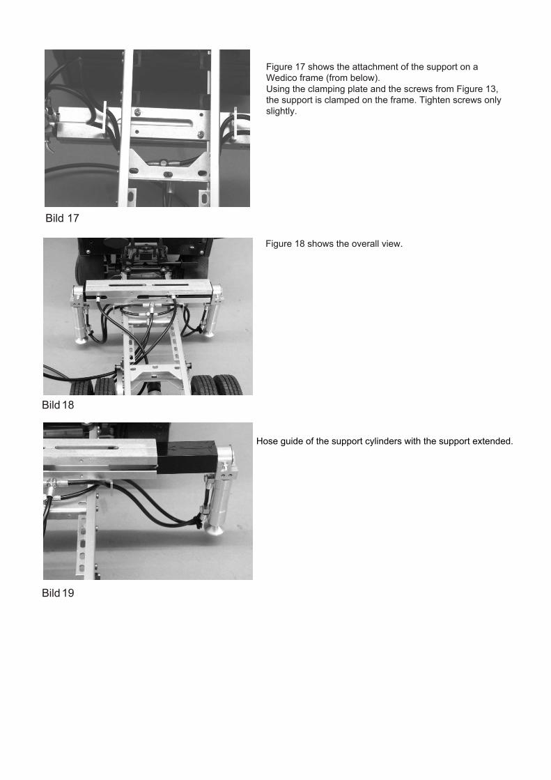
Bild 17
Bild 18
Bild 19
Figure 17 shows the attachment of the support on a Wedico frame (from below). Using the clamping plate and the screws from Figure 13, the support is clamped on the frame. Tighten screws only slightly.
Figure 18 shows the overall view.
Hose guide of the support cylinders with the support extended.