building construction and method and kit therefore
TRANSCRIPT

United States Patent [191 Kragt
[11] 4,115,967 [45] Sep. 26, 1978
[54] BUILDING CONSTRUCTION AND METHOD AND KIT THEREFORE
[75] Inventor: Gerald A. Kragt, Marne, Mich.
[73] Assignee: Jer Manufacturing, Inc., Coopersville, Mich.
[21] Appl. No.: 853,104 [22] Filed: Nov. 21, 1977
[51] Int. 01.2 .............................................. .. E0413 7/02 [52] U.S. Cl. . . . . . . . . . . . . . . . . . . . .. 52/90; 33/174 B
[58] Field of Search .................................... .. 52/90-93, 1 52/86, 64, 643, 478; 33/ 174 B, 174 G
[56] References Cited U.S. PATENT DOCUMENTS
3,394,961 7/1968 Matte ............................ .j. ...... .. 52/64
3,943,672 3/1976 O’Sheeran .... ..
3,999,338 12/1976 Behan et a1. ........................... .. 52/92
Primary Examiner-James L. Ridgill, Jr. Attorney, Agent, or Firm-Price, Heneveld, Huizenga & Cooper [57] ABSTRACT This invention relates to a building construction and method and a kit therefor wherein preferably a spaced front and back end panels are provided with spaced guide blocks positioned on the end panels for receiving therebetween purlins which extend between the end panels. Preferably a templet is used to determine the silhouette of the panels and the position of the guide blocks. The purlins are attached to each of the end panels and are guided to and supported in the correct position by the guide blocks. This construction is rela tively simple and inexpensive by minimizing the re quirement of fabrication of subassemblies such as rafter supports and the like. -
13 Claims, 9 Drawing Figures

US. Patent Sept. 26, 1978 Sheet 1 of2 4,115,967.
M“
- Sheet 2 of 2 4,115,967 U.S. Patent Sept. 26, 1978
4,115,967 1
BUILDING CONSTRUCTION AND METHOD AND KIT THEREFORE
BACKGROUND OF THE INVENTION
(1) Field of the Invention This invention relates to building construction in
general; and, more particularly, to the means for and method of constructing a building and to a kit for sale in constructing a building.
(2) Prior Art _ Wood yard buildings are known in the prior art and
include various precut and prenumbered components which are used in conjunction with detailed illustrated instructions to complete the building. For example, such a building construction can in
10
clude fabrication of a base, attachment of sidewalls to ' the base, attachment of a rear wall to the base and side walls, and attachment of a front wall to the base and sidewalls opposite the rear wall. The framing of the roof has included fabricating subassemblies including rafters. These rafter roof subassemblies can resemble a pair of adjacent rectangles and are attached between the front and rear walls and to the sidewalls. The rafters in the subassembly extend parallel to the upper portions of the front and back end panels which de?ne the roof silhou ette. A problem with such an assembly and construction as
described above is that the rafter assembly must be separately constructed and then positioned within the already assembled side, back and front walls. As a re sult, a great deal of care must be taken to ensure that the sides of the rafter subassembly are of a shape and size to be positioned within the partially completed structure. Such a requirement for cooperation between two inde pendently fabricated assemblies undesirably increases the skill and care required and the difficulty of con struction. ‘
It is desirable and this invention provides a building construction and method of constructing which is sim pler, faster and uses less material while maintaining the desired strength of the building.
SUMMARY OF THE INVENTION ‘
This invention advantageously utilizes the strength of front and rear end panels of a building and purlins ex tending between the end panels to support the roof structure. As a result in accordance with an embodi ment of this invention, conventional rafter supports spaced from the end panels and rafter subassemblies need not be used. Further, a kit for the construction of a building in accordance with an embodiment of this invention can include a templet which de?nes the sil houette of the end panels of the building and the posi tion of the purlins when they abut each end panel. The building construction kit also includes guide blocks which can be attached to the end panels at spaced posi tions to de?ne a recess between the blocks. The blocks are positioned so that at the position of the recess the ends of the purlins join the end panels.
In accordance with an embodiment of this invention, the structural framework of the building is de?ned by the assembly of the purlins and the end panel and the remainder of the building is coupled to the framework. This is in contrast to the known prior art wherein the structural framework has components in addition to purlins and end panels and includes for example, rafter subassemblies which must be then ?tted into a partially
20
25
30
45
2 constructed structural framework. Supporting the pur lins only adjacent the front and. back end panels and, particularly, the use of guide means on the end panels for positioning the purlins, simpli?es construction. Thus, this invention has the advantage of not only pro viding and easier construction and reducing fabrication time but also reducing the chance for error in construc tion of the building which could reduce the structural stability of the building. Pre-assembled rafter sub assem blies are eliminated from construction of the building, thus reducing time and expense of fabrication.
Also, greater advantage is taken of the structural strength of the end panels by transferring the weight of the roof on the purlins to the end panels. Indeed, in accordance with an embodiment of this invention, the silhouette of the end panels can advantageously have a generally arched shape to better support and distribute the weight of the roof. That is, since an arch can carry weight better than a horizontal surface, the top silhou ette of the end panels is closer to an arch than in the prior art.
BRIEF DESCRIPTION OF THE DRAWINGS
FIG. 1 is a front perspective view of a building in accordance with an embodiment of this invention; FIG. 2 is a top plan, view of a templet used to de?ne
the silhouette of half an end panel. of construction mate rial; FIG. 3 is a front elevation view of the inside of half of
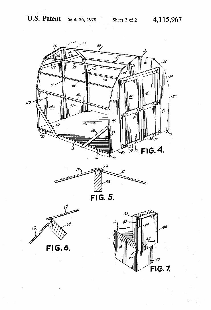
an end panel for the building, the end panel having attached thereto guide blocks for receiving therebe tween the ends of the purlin, and showing in dotted outline the edges of the portion removed from a rectan gular construction sheet to form half the end panel; FIG. 4 is a front perspective view of a partially con
structed building in accordance with an embodiment of the invention with‘ the front and back end panels in place, including temporary construction braces; FIG. 5 is a vertical section view of the ridge of the
building taken generally along line V-V of FIG. 1; FIG. 6 is a vertical section view of the ridge of the
building taken generally along line VI--VI of FIG. 1;‘ FIG. 7 is a front perspective view of a partially com
pleted bottom corner of the building including the abut ment of the ?oor and against the side of an end panel and a nail in phantom; FIG. 8 is a side elevational view taken generally
along line VIII-VIII of FIG. 3 of the connection be tween a guide block and an end panel with a nail before
' bending shown in phantom; and
65
FIG. 9 is top plan view of a portion of a cut end panel which has been marked in accordance with the templet.
DETAILED DESCRIPTION OF THE I INVENTION
Referring to FIG. 1, a building 10 includes a gener ally rectangular base 16 upon which is positioned a front end 12 and an opposing back end 13 (FIG. 4). Generally rectangular and planar sidewalls 11 extend along opposing edges of base 16 between front end 12 and back end 13. Extending between the top edges of ends 12 and 13 above sidewalls 11. and over base 16 is a roof 14 including roof sheathing or panels 17. Front end 12 has formed therein a door 15. Base 16 is formed of a generally planar piece of floor construction material 18 supported off the ground by a plurality of spaced joists 19. Alternatively, the base can be formed of concrete

4,115, 3
with protruding studs for attachment to side walls 11 and ends 12 and 13.
Front end 12 and back end 13 are generally planar panels with a horizontal bottom edge 65 abutting the end of base 16, and a pair of generally vertical opposing 5 side edges 23 abutting side walls 11 (FIG. 4). Referring to FIG. 7, a left front panel 42 forming half of front end 12 is attached by nails 63 to the front end of ?oor mate rial 18 so that the bottom edge of front panel 42 is ?ush with the bottom surface of ?oor material 18. Nails 63 also connect a trim piece 46 to the outside of front panel 42. A side block 30 is attached to the inside of front panel 42 as later discussed and nailed to floor material 18 by a toed-in nail 64 shown in phantom. Extending between the upper portion of side edges 23 and opposite from bottom edge 65 is a six-sided roof edge, generally forming a six-sided arch between the upper portions of the two side edges 23. The roof edges include, in as cending order, a pair of lower roof edges 24, a pair of middle roof edges 25, and a pair of upper roof edges 26. Typically, the front and back ends 12 and 13 are formed from an integral number of standard 4 feet by 8 feet construction panels. For example, the bottom edge 65 of front end 12 can be less than 8 feet long and the maximum height of front end 12 can be 8 feet so the entire front end can be formed from two adjacent 4 foot by 8 foot panels with the silhouette of the end cutout. In the illustrated embodiment of FIGS. 1 and 4, two 4 foot by 8 foot panels have been used so that there is a left back panel 40, a right back panel 41, a left front panel 42 and a right front panel 43.
Referring to FIG. 3, left back panel 40 has a plurality of guide blocks positioned around the side and roof edges and spaced from one another to receive therebe tween ends of purlins extending from front end 12 to back end 13. More speci?cally, a side block 30 extends from the bottom edge 65 of left back panel 40, along side edge 23 to the ?rst of three roof edge portions. Extending along the roof edge portions, but spaced from one another, are, in order, lower roof block 31 along lower roof edge 24, middle roof block 32 along middle roof edge 25, and upper roof block 33 along upper roof edge 26. Referring to FIG. 4, each of panels 40, 41, 42 and 43 have a similar arrangement of blocks 30, 31, 32 and 33 so that purlins can extend between ends 12 and 13 and be positioned between adjacent blocks in each end. That is, a lower purlin 50 extends between the opposing spaces between blocks 30 and 31, a middle purlin 51 extends between the opposing spaces between blocks 31 and 32, an upper purlin 52 extends between the opposing spaces between blocks 32 and 33, and a peak or ridge purlin 53 extends between the op posing spaces between adjacent blocks 33 on adjacent panels 40, 41 and 42, 43. In all, there are seven purlins extending between front and back ends 12 and 13. If 55 additional rigidity is desired, block 30 can be trans versely cut into two pieces and a space 30a (shown in dotted outline on FIG. 3) formed halfway up side edge 23. Thus, an additional purlin can be used extending between the midpoints of opposing side edges 23. The purlins not only improve the relative stability of the front and back panels but provides an additional an choring point for attaching side walls 11.
Referring again to FIG. 1, roof 14 consists of a plural ity of roof panels 17 which have a length somewhat longer than the length of a purlin and a width about equal to the separation between adjacent purlins. Side walls 11 are somewhat longer than the length of a purlin
20
25
40
65
967 4.
so they can extend ?ush with the front surface of trim 46 (FIG. 7) and about equal in width to the distance between lower purlin 50 and base 16. The upper edge of sidewall 11 is connected to lower purlin 50 and the lower edge of sidewall 11 overlaps and is connected to ?oor material 18. Roof panels 17 overlap each other as shown in FIGS. 5 and 6. The roof panel 17 between lower purlin 50 and middle purlin 51 is connected to and flush against the outer edge of middle purlin 51 and overlaps sidewall 11 and lower purlin 50. Similarly, a roof panel 17 will overlap the roof panel 17 just below it. FIG. 6 shows a nail 69 extending through two over lapping roof panels 17 into purlin 52. The contents of a kit to fabricate building 10 includes
a templet 20 shown in FIG. 2. In accordance with one embodiment of this invention, templet 20 ?ts over a standard size panel and can be used to guide the tracing of the silhouette of panels 40, 41, 42 and 43. Templet 20 includes a width alignment edge 21 for lining up along the width or transverse edge of a standard size panel and a length alignment edge 22 for aligning along the longitudinal edge of the standard panel. Templet 20 can be a single piece, or be cut along dotted lines 34 shown in FIG. 2 into three pieces. Advantageously, as shown, the cuts along dotted lines 34 form interlocking dovetail pieces which can be easily and securely assembled and disassembled. A typical material for templet 20 is corro gated cardboard. For de?ning the silhouette of the end panels, templet
20 has a side edge 23a which defines the edge of the end panel to abut sidewall 11. Side edge 23a is parallel to length alignment edge 22 and is spaced from alignment edge 22. Adjacent side edge 23a is a lower roof edge 240 which is angled from side edge 23a 15° and separated from side edge 230 by a lower notch 27 which is suffi ciently wide to provide space for the abutment of lower purlin 50. A middle notch 28 is between lower roof edge 24a and an adjacent middle roof edge 25a. Simi larly, an upper notch 29 is between middle roof edge 25a and an upper roof edge 26a. Middle notch 28 pro vides for the abutment of middle purlin 51 and upper notch 29 provides for the abutment of upper purlin 52. Middle roof edge 25a is at an approximately 45° angle
from the vertical and upper roof edge 26a is at an ap proximately 15° angle from the horizontal. If purlins 50, 51, 52 and 53 use standard 2 inch by 4 inch lumber then the width of each of notches 27-29 is about 1% inches. The tracing of notch 28 on left back panel 40 is shown in FIG. 9. A kit also advantageously includes the blocks 30, 31,
32, 33 which are typically various lengths of 1 inch by 4 inch lumber which lengths correspond with the edges 23, 24, 25, and 26. Side blocks 30 extend along side edges 23, lower roof blocks 31 extend along lower roof edges 24, middle roof blocks 32 extend along middle roof edges 25 and upper roof blocks 33 extend along upper roof edges 26. Upper roof block 33 is chosen to be suf?ciently short so that when the sides of panels 40 and 42, are abutted to the sides of panels 41 and 43, respec tively, there is enough space between adjacent upper roof blocks 33 to pass ridge purlin 53. The ends of blocks 30, 31, 32 and 33 are angled so that ends of adja cent blocks are parallel and so that when purlins 50-53 are positioned between adjacent ends an edge of the purlin faces outwardly and generally parallel to the adjacent one of side or roof edges 23-26. The position of blocks 30-33 on left back panel 40 is shown in FIG. 3 as is a dotted outline 66 of the portion of a standard

5 size panel removed to form panel 40. Also shown is a dotted outline 67 where panel 40‘is cut to form one-half of door 15. Trim pieces 46 are attached along both sides of outline 67 and along the periphery of each half of door 15 to reinforce the edges of door 15 and to mount hinges 47 (FIGS. 1 and 4). FIG. 8 shows how a block such as 30 is nailed to panel 40 and a nail 68 protruding beyond the back of panel 40 bent down. The additional components of building 10 are advan
tageously formed of standard size lumber and can be formed relatively quickly using straight cuts and tem plet 20. Thus, if 4 foot by 8 foot panels are used the distance between front and back ends 12 and 13 is about 8 feet and the distance between adjacent purlins 50, 51, 52, and 53 is about 4 feet so each panel can be cut longi tudinally in‘ the middle to form two roof panels 17. Advantageously, sidewall 11 is the size of one 4 foot by 8 foot panel. The components of building 10 are con nected and assembled by the use of nails.
Referring to FIG. 4, door 15 has symetric opposing door sections 44 and 45 formed cutout of a portion of panels 42 and 43, respectively. Elongated trim pieces 46 around the periphery of sections 44 and 45 and those portions of panels 42 and 43 adjacent door sections 44 and 45 provide reinforcement for door 12 (FIG. 1). Further, six hinges 47, three on each side, are mounted on trim pieces 46 to pivotally mount door sections 44 and 45 to panels 42 and 43, respectively. A hasp 48 is attached to door 15 so it can be locked. A typical mate rial for trim pieces 46 is 1 inch by 4 inch lumber with a length equal to the length of the edge adjacent to which they are mounted. A kit in accordance with an embodiment of this in
vention can also include all of the necessary compo nents cut to the correct size and, if desired, partly pre fabricated. For example, a kit can include precut end panels, purlins, guide blocks, ?oor material, joists, side walls, roof panels, trim pieces and hardware. If the end panels are already cut, there is no need to include tem plet 20 as part of the kit. However, because of the size of the end panels, it is desirable to cut off the top portion of the end panels tofacilitate shipping. An advanta geous cut to make in panels 40, 41, 42 and 43 is a hori zontal out six feet up from the bottom. This not only reduces the shipping dimensions of the pieces to be shipped, but forms the top edge of door 15.
Referring to FIG. 4, left back panel 40 includes a lower portion 40a and an upper portion 40b attached to each other by a horizontal lumber piece 35. Similarly, right back panel 41 includes a lower portion 41a and an upper portion 41b attached to each other by an exten sion of lumber piece 35. Upper portions 40b and 41b are attached to each other by a vertical lumber piece 36 and lower portions 400 and 41a are connected to each other by a vertical lumber piece 37. Lumber pieces 35, 36 and 37 are typically 1 inch by 4 inches, but can be 2 inches by 4 inches, and are nailed to adjacent panel portions so each lumber piece overlaps both ‘adjacent panels. If desired, upper portions 40b and 41b can be preassem bled to each other so a kit for back end panel 13 includes three separate panel portions, the ?rst being panel por tion 400, the second being panel portion 41a, and the third being the combination of panel portions 40b and 41b. Further, door 15 can be completely formed by attaching trim pieces 46 around panels 44 and 45. Still further, the components of building 10 can be painted so that painting is not required after assembly. It can be appreciated that the relative size of pieces 40a and 40b,
4,115,967
5
20
40
45
55
60
65
6 and 41a and 41b can be varied so there is a horizontal lumber piece extending between the ends of purlins 50 across the back of building 10. In such a case, a lumber piece longer and positioned lower than piece 35 is used instead of lumber piece 35.
METHOD OF ASSEMBLY
To fabricate a building 10 in accordance with an embodiment of this invention, templet 20 is positioned on a 4 foot by 8 foot sheet of siding so that the width alignment edge 21 is along the 4 foot side of the sheet and length alignment edge 22 is along the 8 foot side of the sheet. The outline of the templet is marked on the sheet so there is drawn side edge 23a, lower roof edge 24a, middle roof edge 25a, upper roof edge 26a, lower notch 27, middle notch 28 and upper notch 29. When marking, if one side of the siding has grooves, or an otherwise irregular surface, the opposite side should be marked. The siding is then cut along the side edge 23, and roof edges 24, 25 and 26. N'otches 26, 27, 28 and 29 are just marked and not cut out (FIG. 9). The notches mark the outline for the abutting of purlins 50, 51 and 52 against the siding. Depending upon how templet 20 is positioned on the siding, there is formed either a left back panel 40, right back panel 41, left front panel 42 or right front panel 43.
Blocks 30, 31, 32 and 33 are positioned on edges 23, 24, 25 and 26, respectively. These blocks are typically elongated 1 inch by 4 inch pieces of lumber with their ends cut so that adjacent blocks have parallel ends. Thus, there is a slot between adjacent blocks having parallel sides which is at least 1% inches wide and is suitable for receiving 2 inch by 4 inch purlins. Door 15 is formed by cutting opposing sections 44
and 45 from left front panel 42 and right front panel 43, respectively. Typically,each door section has a length of 6feet and a width of 2 feet. Further, trim pieces 46 are attached by nails to the periphery of each of door sec tions 44 and 45 and around the adjacent panels of 42 and 43. As noted, trim pieces 46 add additionalreinforce ment and can be used for attaching hinges 47 and other hardware. A particularly advantageous method of fab rication is to attach a trim piece which is double the width of trim piece 46 around the outline of door 15 so half of the trim piece is on each side of the cut to be made. Thus when sections 44 and 45 are cut from panels 42 and 43, trim pieces 46 are cut longitudinally in half. As the cut is made around the periphery of door 15 hinges 47 are attached sequentially. As a result, door 15 has a perfect ?t and need not be hung. A trim piece (not shown) can be attached to the inside of the vertical center seam in door 15 to seal any space between adja cent door panels and to act as a door stop.
Base 16 is formed of two adjacent 4 foot by 8 foot sheets of ?oor material 18 laid crosswise thus giving a ?oor area of about 8 feet by 8 feet. Of course, different sizes of building 10 ?oor space are possible. Floor mate rial 18 is raised from the ground by parallel 4 inch by 4 inch lumber joists '19connected across adjacent sheets of material 18. After front and back ends 12 and 13 are fabricated, including door 15, they are attached by nails to the front and back of base 16 (FIG. 7). Additional temporary stability during assembly can be provided by having an angular brace 69 (FIG. 4) extending between the sides of front end 12 and base 16. Such a brace is removedbefore sidewalls 11 are attached.
After front and back ends 12 and 13 are standing upright from base 16, purlins 50, 51, and 52 are posi

4,115,967 7
tioned into notches 27, 28, and 29 on both front and back ends 12 and 13. The notch for purlin 53 is formed between adjacent upper roof blocks 33. To secure the purlin, 8D, or penny nails can be driven through the end panels and longitudinally into the purlins. When the purlins are in place, sidewalls 11 are positioned between lower purlin 50 and base 16 and between front and back ends 12 and 13. To facilitate installation of side walls 11 so the bottom of side wall 11 is ?ush with the bottom of ?oor material 18, temporary support blocks 70 are at tached to the side of joists 19 so side wall 11 can rest on the top of blocks 70 while it is nailed to front and back ends 12 and 13, purlin 50 and ?oor material 18. After a sidewall 11 is attached on one side of building 10, a sidewall 11 is attached to the other side also. Three 4 foot by 8 foot panels are cut longitudinally
along their center axes to form six 2 foot by 8 foot pan els which are positioned between purlins 50, 51, 52 and 53 and adjacent the roof edges 24, 25, 26 of each of the front and back ends 12 and 13. If desired, the installation of ridge purlin 53 can be delayed until after sides 11 are attached. To increase the water tightness of building 10, the top edge of the lower roof panels 17 should be tucked under the lower edge of the higher roof panels (FIG. 6). Nails, such as an SD penny nail, are then driven through both of the overlapping roof panels and into the underlying purlin. Further, to insure water tightness a strip of waterproof material 71 can be placed along the joint between the two uppermost roof panels 17 above ridge purlin 53, (FIG. 5). Building 10 can be painted and stained if desired and can include the addi tion of shingles on panels 17 of roof 14. When the building construction kit includes all pre
fabricated components, no cutting is necessary and just assembly of all the components is required. However, as mentioned above, the end panels come in three pieces for ease of shipment. In this case the bottom portions such as 4011 and 41a of back end panel 13 and the lower portion, including the assembled door and trim. pieces 46, of front end panel 12 are attached to base 16. The upper portions are then attached by a horizontal lumber piece (e.g. piece 35) on the inside of the lower portions of the end panels.
Various modi?cations to the preferred embodiments will, no doubt, occur to those skilled in the various arts to which this invention pertains. For example, the par ticular sizes of the building components may be varied from that disclosed above. Further, the building may also include windows. These and all other variations which basically rely on the teachings through which this disclosure has advanced the art are properly consid ered within the scope of this invention as de?ned by the appended claims. The embodiments of the invention in which an exclu
sive property or privilege is claimed are de?ned as follows: .
1. A building having a roof, side walls and end walls including:
a pair of spaced parallel end panels, each of said end panels formed of planar sheet material having gen erally the same silhouette and including roof line and side wall edges extending from the ?oor to the roof line and each panel being formed prior to assembly as a separate integrally formed panel member for an entire end wall of the building con struction;
guide means attached to the inside surface of each of said end panels at spaced intervals along its periph
10
25
40
45
55
65
8 cry for positioning the ends of purlins at positions along said periphery;
a plurality of purlins having a length being generally equal to the distance separating said end panels, said purlins being located, abutted against, and attached to the planar sheet material of said end panels so that the ends of said purlins cooperate with said end panels to form the frame structure for the building;
said purlins including roof purlins located at spaced intervals along said roof line edges at each of said guide means, and at least one purlin located adja cent each of the junctures of the roof line edges and sidewall edges of said end panels; and
side and roof panel members attached to the outer edges of said purlins and end panels thereby enclos ing the building.
2. The building construction of claim 1 in which the integrally formed panel members are formed from at least two pieces of planar sheet material secured to gether along edges thereof.
3. A building construction as recited in claim 1 wherein:
said end panels each have a generally horizontal bot tom edge, a pair of opposing sidewall edges ori ented generally vertically and extending upward from the ends of said bottom edge, a ?rst pair of roof edges extending generally upward from the top of said sidewall edges and angled toward each other, a second pair of roof edges extending gener ally upward from the top of said ?rst pair of roof edges and angled toward each other more than said ?rst pair of roof edges, and a third pair of roof edges extending generally upward from the top of said second pair of roof edges and angled toward each other more than said second pair of roof edges and meeting at the uppermost portion of said end panels;
said guide means include a plurality of elongated blocks with ends for abutting said purlins, a ?rst pair of said blocks being positioned along said ?rst pair of roof edges, a second pair of said blocks being positioned along said second pair of roof edges, a third pair of said blocks being positioned along said third pair of roof edges, and a fourth pair of said blocks being positioned along said sidewall edges so that the longitudinal axis of each of said blocks is substantially parallel to the edge along which it is positioned, the block is generally ?ush with the adjacent edge, there is suf?cient space between the ends of adjacent blocks to receive therebetween the end of a purlin for attaching to the end panel, and the ends of adjacent blocks facing the same purlin are generally parallel; and
a ?rst pair of purlins extends from the spaces between said fourth and ?rst pairs of said blocks on one of said end panels to corresponding spaces on the other of said end panels, a second pair of purlins extends from the spaces between said ?rst and second pairs of said blocks on one of said end pan els to corresponding spaces on the other of said end panels, a third pair of purlins extends from the spaces between said second and third pairs of said blocks on one of said end panels to corresponding spaces on the other of said end panels, and a fourth purlin extends from the space between said third pair of said blocks on one of said end panels to a

side walls with purlins extending between the end walls, said kit including: '
4,115,967 9
corresponding space on theother of said end pan els; and ' “ ' i ‘ "
generally planar roof panels sized to cover the area bounded by adjacent purlins and by guide means between said adjacent‘ purlins,- said roof panels 5 being connectedto said adjacent purlins.
4. A building construction as recited in claim 3 fur ther comprising:
a pair of side panels extending between correspond ing sidewall edges on opposing end panels so that the top edge of said side panels can be attached to said ?rst pair of purlins; ‘
a ?rst pair of roof panels for covering the area bounded by said ?rst pair of roof edges on oppos ing end panels and said ?rst and second pairs of 15 purlins, each of said ?rst pair of roof panels extend ing over the top edge of the adjacent side panel;
a second pair of roof panels for covering the area bounded by said second pair of roof edges on op posing end panels and said second and third pairs of 20 purlins, each of said second pair of roof panels extending over the top edge of the adjacent one of said ?rst pair of roof panels; and
a third pair of roof panels for covering the area bounded .by said third pair of roof edges on oppos ing end panels and said fourth purlin and said third pair of purlins, each of said third pair of roof panels extending over the top edge of the adjacent one of said second pair of roof panels.
5. A building construction as recited in claim 1
10
25
30 wherein:
said guide means including a plurality of raised blocks, adjacent blocks being spaced suf?ciently far apart to receive therebetween the end of a pur~ lin.
6. The building construction of claim 2 in which the 35
blocks are located along the periphery of said end pan els and extend the entire distances between each of said purlins.
7. A building construction as recited in claim 2 40 wherein said guide means includes:
a ?rst raised block extending along at least a portion of said roof edge; ,
a second raised block extending along at least a por tion of said sidewall edge; and a
said ?rst and second raised blocks being spaced apart a distance toreceive and position therebetween the end of a purlin.
8. A kit for construction of a building having end and
45
50
a templet for use in scribing the silhouette of the end walls on rectangular planar sheets of material which form the end panels which are to support purlins extending therebetween;
said templet including alignment edges for aligning ‘said templet with the edges of said rectangular planar sheets and other edges which de?ne the side and roof line edges of at least a portion of the sil houette of the building;
said templet also including projecting means located at spaced intervals along the side and roof line edges for indicating the abutting position of the ends of the purlins on the said end panels; and
elongated blocks for attaching to the said planar sheets, said blocks being sized to correspond with the lengths of said side and roof line edges of said templet; said blocks being adapted to be attached to
55
60
65
10 ,
and extend along a,v portion of the silhouette de?ned by said templet and to ‘be scribed on ‘said planar sheets so as to be spaced from one another at the abutting positionv of the purlins as de?ned by the projecting means of said templet.
9. A kit as recited in claim 8 further comprising; elongated trim means for attaching around the edges
of the end panels,‘ said trim means including a plu rality of lumber pieces, with lengths corresponding to the length of the side and roof line edges of the template.
10. Components included in a kit and sold for use with said kit for constructing a building having end and side walls with purlins extending between the end walls, said parts including: '
a plurality of rectangular planar sheets of material for forming said end walls; a templet for use in scribing the silhouette of the said end walls on said planar sheets of material;
said templet including alignment edges for aligning said templet with the edges of said rectangular planar sheets and other edges which de?ne side and roof line edges of at least a portion of the silhouette of the building;
said templet also including projecting means located at spaced intervals along the side and roof line edges for indicating the abutting position of the ends of the purlins on the said end panels;
guide means adapted to be attached to said planar sheets at a position de?ned by the projecting means of said templet, said means being adapted to locate the purlins on said planar‘sheets and assist in re stricting the purlins from moving laterally along the edges of the planar sheets;
a plurality of purlins having a length approximating the length of the building, said purlins being adapted to be attached to said planar sheet mate rial; and
side and roof panels sized and adapted to be attached to the outer edges of said purlins and the shaped end panels formed by said planar sheets and guide means.
11. The components of claim 10 in which planar sheets of material include at least two pieces for each end panel; and
elongated connecting strips for attaching adjacent edges of said pieces of each end panel together.
v12. The components as recited in claim 10 in which the guide means includes: ‘
elongated blocks for attaching to the said planar sheets, said blocks being sized to correspond with the length of said side and roof line edges of said templet; said blocks being adapted to be attached to and extend along a portion of the silhouette de?ned by said templet and to be scribed on said planar sheets so as to be spaced from one another at the abutting position of the purlins as defined by the projecting means of said templet.
13. A kit for construction of a building having end and side walls with purlins extending between the end walls, said kit including:
a templet for use in scribing the silhouette of the end walls on rectangular planar sheets of material which form the end panels which are to support purlins extending therebetween;
said templet including alignment edges for aligning said templet with the edges of said rectangular planar sheets and other edges which de?ne the side
4,115,967 11 ' 12
and roof line edgFs Pf at least a Portion of the Sn‘ sheets at a position de?ned by the projecting means houette of the bu?dmg; of said templet, said means being adapted to locate
said templete also including projecting means located . . . . at spaced intervals along the Side and roof line the purhns on said planar sheets and assist 1n re edges for indicating the abutting position of the 5 striding the Purlins from moving laterally along ends of the purlins on the said end panels; and the edges of the Planar sheets
guide means adapted to be attached to said planar ‘ "‘ “‘ * *
1O
15
20
25
30
35
45
55
65

0 UNITED STATES PATENT AND TRADEMARK OFFICE
CERTIFICATE OF CORRECTION PATENT NO. : 4,115 ,967
DATED 1 September 26, 1978 a |NVENTOR(S) : Gerald A. Kragt
It is certified that error ‘appears in the above-identified patent and that said Letters Patent are hereby corrected as shown below:
Q Column 6, line 37; "6feet" should be --— 6 feet --—;
Column 9, line 36; "2" should be --— 5 --—;
Q Column 11, line 3; "templete" should be -—- templet ——- . A
Signed and Scaled this ‘ - " ' Fourth D3)’ or September 1979
[SEAL] Attest:
q LUTRELLE F. PARKER ' Attestillg O?ieer Acting Commissioner of Patents and Trademarks