build and drive thelamborghini
TRANSCRIPT

Pack 11
Advanced technology3cc nitro engine All-wheel drive
R A D I O - C O N T R O L L E D C A R W I T H N I T R O E N G I N E
LamborghiniBuild and Drive the
™

170170
CONTENTS
™
www.model-space.com
NOT SUITABLE FOR CHILDREN UNDER THE AGE OF 14. THIS PRODUCT IS NOT A TOY AND IS NOT DESIGNED
FOR USE IN PLAY. ITEMS MAY VARY FROM THOSE SHOWN. THERE MAY BE COLOUR VARIATIONS
OWING TO THE MATERIALS USED.
All rights reserved © 2016
Published in the UK by De Agostini UK Ltd, Battersea Studios 2, 82 Silverthorne Road, London SW8 3HE
Published in the USA by De Agostini Publishing USA Inc., 915 Broadway, Suite 609, New York, NY 10010
English adaptation by Continuo Creative, 39-41 North Road, London N7 9DP
Printed in the EU.
The trademarks, copyrights and design rights in and associated with Lamborghini, Lamborghini with Bull and Shield Device are used under licence from Automobili Lamborghini S.p.A., Italy.
Picture credits:Cover © Automobili Lamborghini S.p.A.; p171-191 Milanoedit srl.
™
R A D I O - C O N T R O L L E D C A R W I T H N I T R O E N G I N E
LamborghiniBuild and Drive the
CONTENTSAssembly Guide
The step-by-step guide to building your Lamborghini Huracán
Stage 60: Bodywork stickers, mirrors and fl ywheel
Stage 61: Clutch and bodywork screws
Stage 62: Pinion gears
Stage 63: The engine mounts
Stage 64: Rear differential
Stage 65: Right front driveshaft

Bodywork stickers, mirrors and fl ywheel
Parts supplied:A Bodywork stickersB Engine cover insertC Engine cover insert stickerD Mirror parts
ASSEMBLY GUIDE – STAGE 60
171
A C D
I
B
F
K
J
E
GG
FHH
171
E Flywheel F O-ringsG Body clipsH Washers
I 2 x 4mm screwsJ Self-locking nuts 3mmK Anti-friction pads
11
1 The tools and materials you need for this stage are some contact adhesive, a pair of scissors, a small Phillips screwdriver, a caliper, a knife, a thin fi le, a tapered reamer and a hair dryer.
170 171
In this stage, you will be working with the body and engine cover insert stickers and the mirror parts, so store away the rest of components supplied – such as the fl ywheel, the anti-friction pads and the body clips – until they are needed. You will also need the bodyshell from Stage 52.

4 Remove the protective fi lm from the sticker on the engine cover insert.
5 Remove the clear protective film from the rear of the bodyshell, then place the engine cover insert into the matching hole at the rear of the bodyshell. To make it stick better, gently warm it with a hair dryer, as shown. This will soften the
2 Prepare the engine cover insert and the engine cover insert sticker.
3 Peel the engine cover insert sticker from its backing sheet, then apply it to the engine cover insert, as shown. Try to be as accurate as you can when lining up the edges.
material and make it adapt more easily to the shape of the bodywork.
6 The rear end of the insert can be hard to fi t, because of the grooves in it. Warm the parts with a hairdryer to make them a little more fl exible, then press them together with your fi ngertips.
ASSEMBLY GUIDE – STAGE 60
172
2 Prepare the 3 Peel the engine
2 3
4
172
6
5

7 Locate the mounting posts on the two mirror supports, and use a caliper to check the width of each one: it should be around 4.5mm (see Step 13).
8 The mirror supports can be identified by the letters ‘R’ or ‘L’ moulded on them (arrowed).
9 Apply the mirror stickers to the mirror backs. As the stickers are small and delicate, you may need to use the tip of a knife to place them onto the backs.
10 Apply a drop of contact adhesive to other side of each mirror back. Stick the backs into the corresponding mirror housings.
11 Stick the backs into the corresponding mirror housings.
12 Apply glue to the posts projecting from the mirror housings. Push the posts into the corresponding holes in the supports. The left housing will only fi t into the left support, and the right housing will only fi t into the right support.
172 173
ASSEMBLY GUIDE – STAGE 60
11 12
7
9
8
10

13 At the front of each door there is a recess for its mirror. Carefully cut through the centre of each recess with a small reamer, and then enlarge the hole to just under 4.5mm in diameter.
14 Using a thin file, create a notch at the front of each hole, as shown, to match the post on the mirror support.
15 This is how the hole in the right-hand side of the bodyshell should now look.
16 Insert the post of one of the mirror supports into its hole in the body. Place an O-ring over the end of the post on the inside of the bodyshell, as shown.
17 Place a washer over the end of the post and secure it with a 2 x 4mm screw.
18 This is how the end of the mirror support post should look once it’s been fi xed into place. Now repeat Steps 16 and 17 for the other mirror.
ASSEMBLY GUIDE – STAGE 60
13 14
15
17
16
18
174174

19 This is the left side of the bodyshell with its mirror in place.
20 Remove all of remaining protective fi lm from the bodyshell, so that you can apply the stickers.
21 First apply the windscreen and door window stickers to the bodyshell. You may need a knife to lift the stickers from the sheet.
22 Here you can see the bodyshell of the Huracán with the
windscreen and window stickers fi tted. Use the hair dryer to smooth out any wrinkles, and if there is an air bubble, pierce it with a pin. The rest of the stickers will be used in a later stage.
19
19 21
21
20
22
174 175174
ASSEMBLY GUIDE – STAGE 60

1
ASSEMBLY GUIDE – STAGE 61
1 As well as the parts supplied with this stage, you will need the engine (Stage 59) and the fl ywheel and nuts (Stage 60).
A
D
C
B
A
Clutch and bodywork screws
176176
Parts supplied:A Clutch shoesB Pilot shaftC Screws 3 x 8mmD Clutch spring
In this stage, you continue assembling the engine and the bodywork. First, you will fit the clutch to the engine, bringing it closer to completion, and then you will add components to the bodyshell and apply more stickers to it.

2 3
5
6
42 The tools you will need are a conical reamer (or a 3mm drill bit), a 5.5mm cross wrench, a Phillips screwdriver, and self-closing needle-nose pliers. You will also need parrot-nose pliers and a 10mm wrench (not shown in the photograph).
3 Take the fl ywheel and place it over the tapered collet, with the pin facing away from the crankcase.
4 Now tighten the pilot shaft onto the end of the crankshaft.
5 Hold the flywheel with parrot-nose pliers, and tighten the pilot shaft with a 10mm wrench.
6 Pass the hook at one end of the clutch spring through the eyelet at the other end, as shown.
176176 177
ASSEMBLY GUIDE – STAGE 61

Air fi lter
11 12
9
7 8
10
ASSEMBLY GUIDE – STAGE 61
178
7 Place the two clutch shoes together in the orientation shown, using the holes as a guide.
8 Hold the two shoes together, and place the spring into the groove around the outer edge. 9 Now place the clutch over the pilot shaft and push it down against the fl ywheel. The pins on the fl ywheel should enter the
corresponding holes in the clutch shoes. The inner diameter of the clutch is smaller than the diameter of the pilot shaft, so you will need to open it with needle-nose pliers.
10 Here’s how the assembled flywheel and clutch should look.
11 You will now need the bodyshell (Stage 60), and the
nose and tail panels (Stages 1 and 2). Remove the protective film from the two panels, and then apply the sticker to the nose panel, as shown.
12 Cut through the centres of the four recesses in the nose and tail panels, using either a reamer or a 3mm drill bit. Open each one to a diameter of 3mm.

13 14
15 16
17 18
178 179
ASSEMBLY GUIDE – STAGE 61
13 This is how the nose and tail should look once you have opened the holes (circled).
14 Open up the two indicated holes in the front of the bodyshell to a diameter of 3mm.
15 Place the bodyshell onto the nose, aligning the indicated holes in both. Insert a 3 x 8mm screw into each of the holes, then turn the assembly over and tighten a nut onto the end of both screws.
16 Now open the hole at each side of the bodyshell to 3mm. Make sure that these holes align with those in the nose.
17 This is how the aligned holes should look, seen from the inside of the nose panel.
18 Fix the panels together with screws and nuts, as in Step 15.

1
22
19 20
21
ASSEMBLY GUIDE – STAGE 61
19 Open up the four indicated holes in the rear of the bodyshell to 3mm in diameter.
20 Fit the tail panel into the rear of the bodyshell, as shown. Align the four holes of both parts, and secure them with screws and nuts, as before. Then apply the two stickers to the tail panel, as indicated by the arrows.
21 Next, apply one of the stickers shown to each side of the bodyshell, just behind the door, as indicated.
22 This is how the bodyshell should now look. Store the remaining stickers for use in future stages.
180

Pinion gears
The parts supplied with this stage are more components for your Huracán’s engine, including the pinion gears that will form the basis of your model’s two-speed transmission. Along with these parts, you will need the engine assembly from the previous stage.
A
Parts supplied:A Pinion gears 15/20TB Ball bearingC Roller BearingD WasherE Screw 3 x 10mm
B
E
D
C
1 For this stage, you will need a small Phillips screwdriver and some multipurpose grease.
2 Insert the ball bearing into the inside of the pinion gears, as indicated below.
180 181
ASSEMBLY GUIDE – STAGE 62
1 For this stage, you will need a small Phillips
181
2
1

3 4
5 6
7 8
ASSEMBLY GUIDE – STAGE 62
182
3 Fit the pinion gears over the clutch, and push them up against the flywheel.
4 Apply a small amount of multipurpose grease to the roller bearing.
5 Insert the roller bearing into the pinion gears, over the end of the pilot shaft.
6 Place the washer onto the shank of the 3 x 10mm screw.
7 Insert the screw into the end of the pilot shaft, and tighten it into place to hold the bearing and pinion gears in position.
8 Your engine assembly should now look like this.

1
2
The engine mounts
The parts provided for this stage include the engine mounts and the fi xing screws with which you will fi t the engine onto chassis plate of your Huracán. Avoid over-tightening the screws when you fi t the engine to the chassis, as you may need to adjust its position at a later stage.
A
A
Parts supplied:A Spring washersB Screws M3 x 12mmC Engine mountsD Screws M3 x 10mm
B
B
D
C
1 For this stage, you will need a 2mm and a 2.5mm Allen key and some thread lock, either low or medium hold.
2 As well as this stage’s parts, you will need your engine assembly from Stage 62.
C
182 183
ASSEMBLY GUIDE – STAGE 63

3 4
5 6
7 8
ASSEMBLY GUIDE – STAGE 63
184
3 Place the four spring washers onto the shanks of the four M3 x 12mm screws, as shown.
4 Insert the screws into the holes on each side of the crankcase. Then apply a drop of thread lock onto the shank of each screw.
5 Take one of engine mounts and place it under the screws on one side of the engine. Tighten the screws into the holes in the top of the mounts.
6 Next, fit the second engine mount to the other side of the engine.
7 Place the engine onto the chassis plate in the position shown, with the pinion gears on the right.
8 Fix the engine to the chassis by inserting the four M3 x 10mm screws into the underside of the plate and tightening them into the bottom of the engine mounts.

1
Rear differential
With this stage, you have received more components for the rear differential. Before you begin assembling it, you will need to retrieve the other rear differential components from Stages 18, 27 and 28. Then follow the steps in Stages 10, 13 and 14 – which showed you how to assemble the front differential – to assemble the rear differential. Once you’ve completed the rear differential, follow the steps in this stage to fit it in place.
E
A
Parts supplied:A Differential greaseB O-ringC Rear differential caseD Side gearE Grub screwF O-ringG ShimH Rear adjustment eccentricI PinJ Ball bearingK Differential shaft
DB
F
C
1 You will now need the main driveshaft and right rear suspension mount assembly (Stage 40), the left rear suspension mount and self-tapping screws (Stage 23), all of the parts provided with Stage 18, and your newly assembled rear differential.
G
H
IJ
K
184 185
ASSEMBLY GUIDE – STAGE 64
ASSEMBLY GUIDE – STAGE 64
2
4
3
5
6 7
186
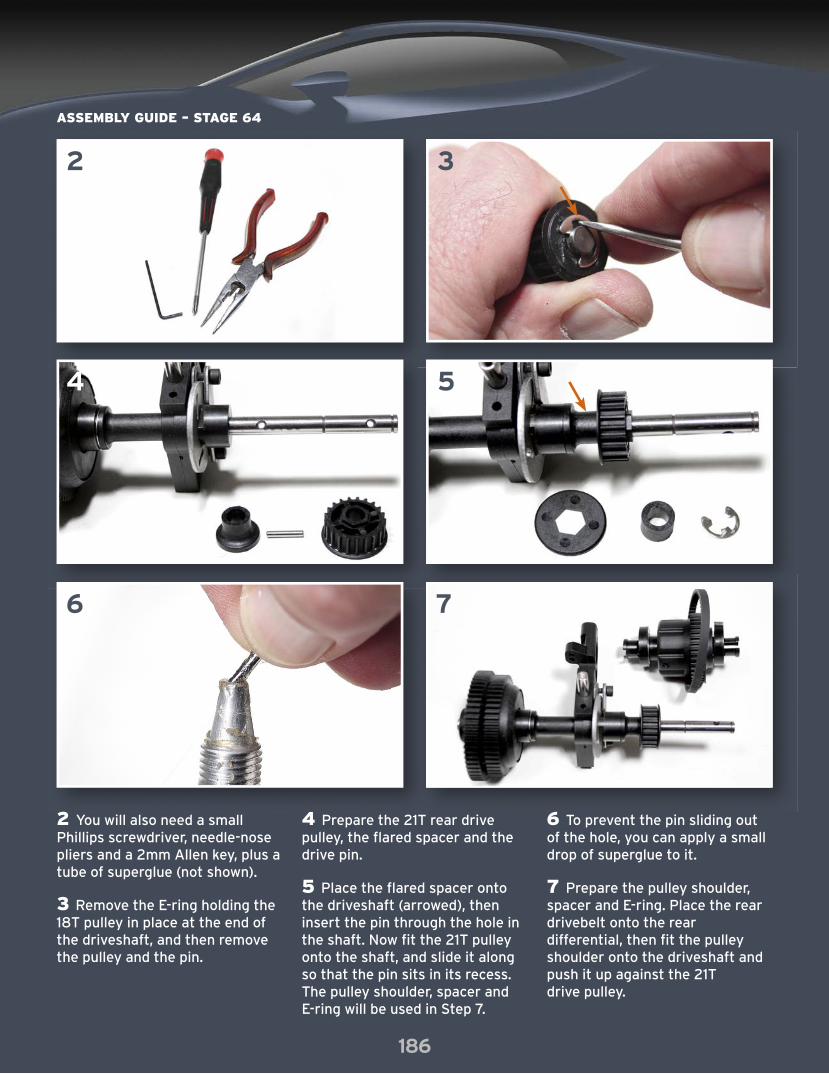
2 You will also need a small Phillips screwdriver, needle-nose pliers and a 2mm Allen key, plus a tube of superglue (not shown).
3 Remove the E-ring holding the 18T pulley in place at the end of the driveshaft, and then remove the pulley and the pin.
4 Prepare the 21T rear drive pulley, the flared spacer and the drive pin.
5 Place the flared spacer onto the driveshaft (arrowed), then insert the pin through the hole in the shaft. Now fit the 21T pulley onto the shaft, and slide it along so that the pin sits in its recess. The pulley shoulder, spacer and E-ring will be used in Step 7.
6 To prevent the pin sliding out of the hole, you can apply a small drop of superglue to it.
7 Prepare the pulley shoulder, spacer and E-ring. Place the rear drivebelt onto the rear differential, then fit the pulley shoulder onto the driveshaft and push it up against the 21T drive pulley.

8 9
10
12
11
13
186 187
ASSEMBLY GUIDE – STAGE 64
8 Insert the rear differential into the hole in the right rear suspension mount, so that the pulley on the differential is aligned with the pulley on the driveshaft. Now pull the drivebelt over the 21T pulley on the driveshaft. The rear adjustment eccentric allows you to adjust the belt tension, but, for now, place it in the position shown in the photo, closer to the rear axle.
9 Place the second spacer onto the driveshaft.
10 Fit the left rear shoulder onto the driveshaft and the rear differential. Push the ball bearing into the recess in the shoulder.
11 Press an E-ring into the groove in the driveshaft to lock the bearing in place.
12 Insert the pin back into the hole at the end of the driveshaft, then put the 18T pulley back into position and fix it with the E-ring.
13 Locate the two circled holes in the chassis plate behind the engine. These will accommodate the two posts on the underside of the shoulders; the other four holes will house screws.

14
16
15
17 18
20
15
19
ASSEMBLY GUIDE – STAGE 64
188
14 This is the central post and the holes either side of it, on the underside of the rear shoulders.
15 Mount the differential/driveshaft assembly on the chassis plate, with the posts of the shoulders in the circled holes.
16 Tighten the four self-tapping screws into the holes either side of the posts.
17 Slightly loosen the four screws that hold the engine support to the chassis plate, to create a gap between the pinion gears and the driveshaft gears. Place some tissue between the teeth of the gears, then push them together and retighten the screws.
18 The correct distance between the pinion and gears is when the
wheels are close enough to leave deep marks on the tissue without tearing through it.
19 When you have the engine in the correct position, tighten the four screws that hold it in place.
20 This stage is now complete, and this is how your model should look with the rear differential/driveshaft assembly in place.

1
Right front driveshaft
The parts supplied with this stage transmit the drive to the right front wheel. They will allow you to fit the right front hub carrier, shoulder, upper and lower arms and disc brake, which will complete the right front suspension assembly. This stage is similar to Stage 44, so you can refer to that for more details.
AParts supplied:A DriveshaftB Flanged nutC Hexagonal drive washerD PinE Stub axle D
B
1 In addition to your new parts, you will need the right front side frame (Stage 9), the right front lower arm assembly (Stage 37), the front brake disc (Stage 47), the right front hub carrier assembly (Stage 8) and the right front upper arm (Stage 44).
CE
188 189
ASSEMBLY GUIDE – STAGE 65
ASSEMBLY GUIDE – STAGE 65
2 43
5 6 7
190
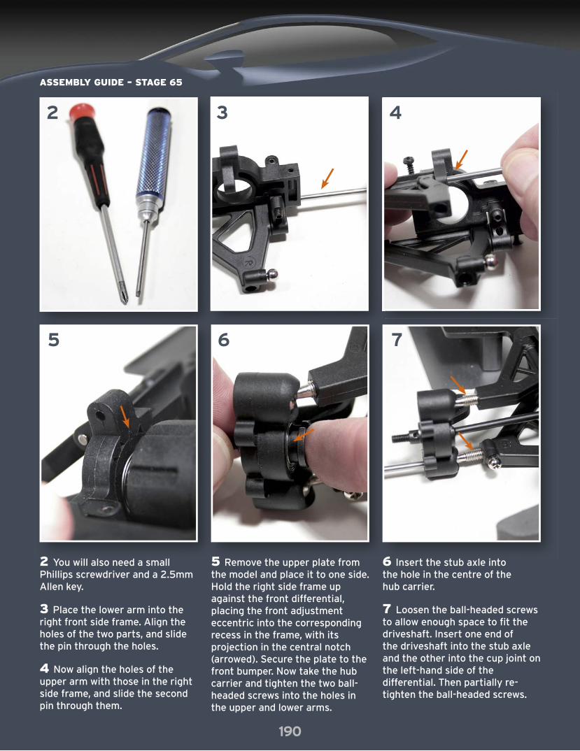
2 You will also need a small Phillips screwdriver and a 2.5mm Allen key.
3 Place the lower arm into the right front side frame. Align the holes of the two parts, and slide the pin through the holes.
4 Now align the holes of the upper arm with those in the right side frame, and slide the second pin through them.
5 Remove the upper plate from the model and place it to one side. Hold the right side frame up against the front differential, placing the front adjustment eccentric into the corresponding recess in the frame, with its projection in the central notch (arrowed). Secure the plate to the front bumper. Now take the hub carrier and tighten the two ball-headed screws into the holes in the upper and lower arms.
6 Insert the stub axle into the hole in the centre of the hub carrier.
7 Loosen the ball-headed screws to allow enough space to fit the driveshaft. Insert one end of the driveshaft into the stub axle and the other into the cup joint on the left-hand side of the differential. Then partially re-tighten the ball-headed screws.

8 9
12 13
10 11
190 191
ASSEMBLY GUIDE – STAGE 65
8 Stop tightening the screws when a few threads are still showing: the axle shaft must have a play of about 1mm.
9 Insert the pin through the hole in the stub axle, as shown.
10 Place the hexagonal drive washer over the stub axle and pin. Then tighten the flanged nut onto the end of the axle.
11 Fit the upper plate back into position, and secure it to the side plates with the two screws.
12 If you didn’t fi t the brake disc to the hub carrier in Stage 47, do so now. The brake caliper must face towards the rear of the model.
13 Here is how the front end of your Huracán should look at the end of this stage.

Assembly Guide
Coming in your next pack
Stage 67Throttle and brake linkages
PARTS SUPPLIEDBrake rod, lever and piston, throttle rod, guides, screws, spring, collars, switch
Stage 66Rear tie rod
PARTS SUPPLIEDBall-headed screws, ball ends, tie rod
Stage 68Second rear shock absorber
PARTS SUPPLIEDShock absorber components
Stage 69Rear wheel and tyre
PARTS SUPPLIEDRear wheel, tyre with foam insert, hubcap, Lamborghini badge sticker
Stage 70Headlights and rear lights
PARTS SUPPLIEDHeadlights and lenses, rear lights and lenses, double-sided tape and double-sided tape strips
R A D I O - C O N T R O L L E D C A R W I T H N I T R O E N G I N E
LamborghiniBuild and Drive the
www.model-space.com
™